android controlled robot car - ijamtes.org · the robot in the project can be made to move in all...
TRANSCRIPT

ANDROID CONTROLLED ROBOT CAR
S. Mohammed Ismail (1), I. Richards Infant Dhanaraj (2), M. Tharik sajeen (3)
1,2,3 PG scholar, Department of Electronics, St.JOSEPH’S COLLEGE
(AUTONOMOUS),Tiruchirappalli,Tamilnadu, (India)
ABSTRACT
The main aim of this project is to create designing a Robot that can be operated using Android Apps. The
controlling of the Robot is done wirelessly through Android smart phone using the Bluetooth module feature
present in it. Here in the project the Android smart phone is used as a remote control for operating the Robot.
Android is a software stack for mobile devices that includes an operating system, middleware and key
applications. Android boasts a healthy array of connectivity options, including Wi-Fi, Bluetooth, and wireless
data over a cellular connection (for example, GPRS, EDGE (Enhanced Data rates for GSM Evolution), and
3G). Android provides access to a wide range of useful libraries and tools that can be used to build rich
applications. Bluetooth is an open standard specification for a radio frequency (RF)-based, short-range
connectivity technology that promises to change the face of computing and wireless communication. It is
designed to be an inexpensive, wireless networking system for all classes of portable devices, such as laptops,
PDAs (personal digital assistants), and mobile phones. The controlling device of the whole system is a
Microcontroller. Bluetooth module, DC motors are interfaced to the Microcontroller. The data received by the
Bluetooth module from Android smart phone is fed as input to the controller. The controller acts accordingly
on the DC motors of the Robot. The robot in the project can be made to move in all the four directions using
the Android phone. The direction of the robot is indicated using LED indicators of the Robot system. In
achieving the task the controller is loaded with a program written using Embedded ‘C’ language.
Keywords: Wireless, Android, Bluetooth, Arduino, Robotic Car
I. INTRODUCTION
Nowadays smart phones are becoming more powerful with reinforced processors, larger storage capacities, richer
entertainment function and more communication methods. Bluetooth is mainly used for data exchange to add new
features to smart phones. Bluetooth technology, created by telecom vendor Ericsson in 1994, shows its advantage by
integrating with smart phones. It has changed how people use digital device at home or office, and has transferred
traditional wired digital devices into wireless devices. A host Bluetooth device is capable of communicating with up to
seven Bluetooth modules at same time through one link. Considering its normal working area of within eight meters, it is
especially useful in home environment. Thank for Bluetooth technology and other similar techniques, with dramatic
increase in Smartphone users, smart phones have gradually turned into an all-purpose portable device and provided people
International Journal of Management, Technology And Engineering
Volume 8, Issue XI, NOVEMBER/2018
ISSN NO : 2249-7455
Page No:2612

for their daily use. In recent years, an open-source platform Android has been widely used in smart phones. Android has
complete software package consisting of an operating system, middleware layer and core applications. Different from
other existing platform like iOS (iPhone OS), it comes with software development kit (SDK), which provides essential
tools and Application. Using a Smartphone as the “brain” of a robot is already an active research field with several open
opportunities and promising possibilities. In this report I present a review of current robots controlled by mobile phone
and discuss a closed loop control systems using audio channels of mobile devices, such as phones and tablet computers. In
my work, move the robot upward, backward, left and right side by the android application such as Arduino Bluetooth RC
Car.
II. METHODOLOGY
Project development is not an easy task. It requires through study of the various component and their outcomes. The
project is effective only if it can fulfill the objective that it aim to provide the project is implemented using various that are
organized in a specific way so that the device is small and portable. Each component has a specific function to perform.
2.1 HARDWARE REQUIREMENT
This part consists of various components, which are as follows.
ARDUINO UNO
DC MOTORS
L293D MOTOR DRIVER
9V BATTERY
ROBOT BODY
BLUETOOTH DEVICE
2.2 SOFTWARE REQUIREMENT
ARDUINO IDE
2.3 ANDROID APPLICATIONS
ARDUINO BLUETOOTH CONTROLLER
International Journal of Management, Technology And Engineering
Volume 8, Issue XI, NOVEMBER/2018
ISSN NO : 2249-7455
Page No:2613

2.4DEVICE IMPLEMENTATION
FIG: 2.4ARDUINO UNO BOARD
Arduino is an open source, computer hardware and software company, project, and user community that designs and
manufactures microcontroller kits for building digital devices and interactive objects that can sense and control objects in
the physical world. The project's products are distributed as open-source hardware and software, which are licensed under
the GNU Lesser General Public License (LGPL) or the GNU General Public License (GPL), permitting the manufacture
of Arduino boards and software distribution by anyone. Arduino boards are available commercially in preassembled form,
or as do-it-yourself kits.
Arduino is open-source hardware. The hardware reference designs are distributed under a Creative Commons Attribution
Share-Alike 2.5 license and are available on the Arduino website. Layout and production files for some versions of the
hardware are also available. The source code for the IDE is released under the GNU General Public License,
version2.Nevertheless, an official Bill of Materials of Arduino boards has never been released by Arduino staff.
Most Arduino boards consist of an Atmel 8AVR microcontroller (ATmega8, ATmega168, ATmega328,
ATmega1280, ATmega2560) with varying amounts of flash memory, pins, and features.The 32-bit Arduino Due, based
on the Atmel SAM3X8E was introduced in 2012.The boards use single or double-row pins or female headers that
facilitate connections for programming and incorporation into other circuits. These may connect with add-on modules
termed shields. Multiple, and possibly stacked shields may be individually addressable via an I²C serial bus. Most boards
include a 5 V linear regulator and a 16 MHz crystal oscillator or ceramic resonator. Some designs, such as the Lily Pad,
run at 8 MHz and dispense with the onboard voltage regulator due to specific form-factor restrictions.
Arduino microcontrollers are pre-programmed with a boot loader that simplifies uploading of programs to the
on-chip flash memory. The default boot loader of the Arduino UNO is the boot loader. Boards are loaded with program
code via a serial connection to another computer. Some serial Arduino boards contain a level shifter circuit to convert
between RS-232 logic levels and transistor–transistor logic (TTL) level signals. Current Arduino boards are programmed
International Journal of Management, Technology And Engineering
Volume 8, Issue XI, NOVEMBER/2018
ISSN NO : 2249-7455
Page No:2614
via Universal Serial Bus (USB), implemented using USB-to-serial adapter chips such as the FTDI FT232. Some boards,
such as later-model Uno boards, substitute the FTDI chip with a separate AVR chip containing USB-to-serial firmware,
which is reprogrammable via its own ICSP header. Other variants, such as the Arduino Mini and the unofficial Boarduino,
use a detachable USB-to-serial adapter board or cable, Bluetooth or other methods, when used with traditional
microcontroller tools instead of the Arduino IDE, standard AVR in-system programming (ISP) programming is used.
The Arduino board exposes most of the microcontroller's I/O pins for use by other circuits. Several plug-in
application shields are also commercially available. The Arduino Nano, and Arduino-compatible Bare Bones Board and
Boarduinoboards may provide male header pins on the underside of the board that can plug into solderless breadboards.
The Arduino/Genuino Uno can be programmed with the (Arduino Software (IDE)). Select "Arduino/Genuino
Uno from the Tools > Board menu (according to the microcontroller on your board). For details, see
the reference and tutorials.
The ATmega328 on the Arduino/Genuino Uno comes preprogrammed with a bootloader that allows you to
upload new code to it without the use of an external hardware programmer. It communicates using the original STK500
protocol (reference, C header files).
The ATmega16U2 (or 8U2 in the rev1 and rev2 boards) firmware source code is available in the Arduino
repository. The ATmega16U2/8U2 is loaded with a DFU boot loader, which can be activated by:
The Arduino Uno has a resettable polyfuse that protects your computer's USB ports from shorts and overcurrent.
Although most computers provide their own internal protection, the fuse provides an extra layer of protection. If more
than 500 mA is applied to the USB port, the fuse will automatically break the connection until the short or overload is
removed.
2.4.1 DIFFERENCES WITH OTHER BOARDS
The Uno differs from all preceding boards in that it does not use the FTDI USB-to-serial driver chip. Instead, it features
the Atmega16U2 (Atmega8U2 up to version R2) programmed as a USB-to-serial converter.
The Arduino Uno board can be powered via the USB connection or with an external power supply. The power source is
selected automatically.
External (non-USB) power can come either from an AC-to-DC adapter (wall-wart) or battery. The adapter can be
connected by plugging a 2.1mm center-positive plug into the board's power jack. Leads from a battery can be inserted in
the GND and Vin pin headers of the POWER connector.
The board can operate on an external supply from 6 to 20 volts. If supplied with less than 7V, however, the 5V pin may
supply less than five volts and the board may become unstable. If using more than 12V, the voltage regulator may
overheat and damage the board. The recommended range is 7 to 12 volts.
International Journal of Management, Technology And Engineering
Volume 8, Issue XI, NOVEMBER/2018
ISSN NO : 2249-7455
Page No:2615

The input voltage to the Arduino/Genuino board when it's using an external power source (as opposed to 5 volts from the
USB connection or other regulated power source). You can supply voltage through this pin, or, if supplying voltage via
the power jack, access it through this pin 5V.This pin outputs a regulated 5V from the regulator on the board. The board
can be supplied with power either from the DC power jack (7 - 12V), the USB connector (5V), or the VIN pin of the
board (7-12V). Supplying voltage via the 5V or 3.3V pins bypasses the regulator, and can damage your board. We don't
advise it.
IOREF-This pin on the Arduino/Genuino board provides the voltage reference with which the microcontroller operates. A
properly configured shield can read the IOREF pin voltage and select the appropriate power source or enable voltage
translators on the outputs to work with the 5V or 3.3V.
The ATmega328 has 32 KB (with 0.5 KB occupied by the bootloader). It also has 2 KB of SRAM and 1 KB of EEPROM
(which can be read and written with the EEPROM library).
See the mapping between Arduino pins and ATmega328P ports. The mapping for the Atmega8, 168, and 328 is identical.
Each of the 14 digital pins on the Uno can be used as an input or output, using pinMode(), digitalWrite(),
and digitalRead() functions. They operate at 5 volts. Each pin can provide or receive 20 mA as recommended operating
condition and has an internal pull-up resistor (disconnected by default) of 20-50k ohm. A maximum of 40mA is the value
that must not be exceeded on any I/O pin to avoid permanent damage to the microcontroller.
Arduino Uno has a number of facilities for communicating with a computer, another Arduino/Genuino board, or other
microcontrollers. The ATmega328 provides UART TTL (5V) serial communication, which is available on digital pins 0
(RX) and 1 (TX). An ATmega16U2 on the board channels this serial communication over USB and appears as a virtual
com port to software on the computer. The 16U2 firmware uses the standard USB COM drivers, and no external driver is
needed. However, on Windows, a .in file is required.
The Arduino Software (IDE) includes a serial monitor which allows simple textual data to be sent to and from the board.
The RX and TX LEDs on the board will flash when data is being transmitted via the USB-to-serial chip and USB
connection to the computer (but not for serial communication on pins 0 and 1).A Software Serial library allows serial
communication on any of the Uno's digital pins.
The ATmega328 also supports I2C (TWI) and SPI communication. The Arduino Software (IDE) includes a Wire
library to simplify use of the I2C bus; see the documentation for details. For SPI communication, use the SPI library.
International Journal of Management, Technology And Engineering
Volume 8, Issue XI, NOVEMBER/2018
ISSN NO : 2249-7455
Page No:2616

2.4.2 TABLE OF CONFIGURATION
Microcontroller ATmega328P
Operating Voltage 5V
Input Voltage (recommended) 7-12V
Input Voltage (limit) 6-20V
Digital I/O Pins 14 (of which 6 provide PWM output)
PWM Digital I/O Pins 6
Analog Input Pins 6
DC Current per I/O Pin 20 Ma
DC Current for 3.3V Pin 50 Ma
Flash Memory 32 KB (ATmega328P) of which 0.5 KB used by bootloader
SRAM 2 KB (ATmega328P)
EEPROM 1 KB (ATmega328P)
Clock Speed 16 MHz
LED_BUILTIN 13
Length 68.6 mm
Width 53.4 mm
Weight 25 g
2.4.2 TECHNICAL SPECIFICATION OF ARDUINO UNO
International Journal of Management, Technology And Engineering
Volume 8, Issue XI, NOVEMBER/2018
ISSN NO : 2249-7455
Page No:2617
2.5DC MOTOR
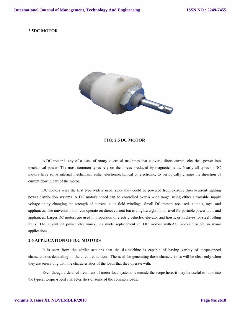
FIG: 2.5 DC MOTOR
A DC motor is any of a class of rotary electrical machines that converts direct current electrical power into
mechanical power. The most common types rely on the forces produced by magnetic fields. Nearly all types of DC
motors have some internal mechanism, either electromechanical or electronic, to periodically change the direction of
current flow in part of the motor.
DC motors were the first type widely used, since they could be powered from existing direct-current lighting
power distribution systems. A DC motor's speed can be controlled over a wide range, using either a variable supply
voltage or by changing the strength of current in its field windings. Small DC motors are used in tools, toys, and
appliances. The universal motor can operate on direct current but is a lightweight motor used for portable power tools and
appliances. Larger DC motors are used in propulsion of electric vehicles, elevator and hoists, or in drives for steel rolling
mills. The advent of power electronics has made replacement of DC motors with AC motors possible in many
applications.
2.6 APPLICATION OF D.C MOTORS
It is seen from the earlier sections that the d.c.machine is capable of having variety of torque-speed
characteristics depending on the circuit conditions. The need for generating these characteristics will be clear only when
they are seen along with the characteristics of the loads that they operate with.
Even though a detailed treatment of motor load systems is outside the scope here, it may be useful to look into
the typical torque-speed characteristics of some of the common loads.
International Journal of Management, Technology And Engineering
Volume 8, Issue XI, NOVEMBER/2018
ISSN NO : 2249-7455
Page No:2618

Loads are broadly divided into,
(a) Passive loads
(b) Active loads
They may be unidirectional in operation or work in either direction (Reversible loads). Passive loads absorb the
mechanical energy developed by the motors while active loads are capable of working as both sinks and sources for
mechanical energy. The direction of rotation may be taken to be clockwise/counter clockwise rotation.
Normally the direction in which the load operates most of the time is taken as the positive direction of rotation.
Any torque which accelerates the motor load system in the positive direction of rotation is termed as a positive toque.
With this rotation torques of motors, generators or loads can be represented graphically on a four quadrant diagram.
The torque being taken as an independent variable is represented along the x-axis. Y-axis represents the speed.
The characteristics a, b, and c correspond to frictional torque, cutting torque and fan torque respectively. While the
frictional torque is not a function of speed, the cutting toque is proportional to the speed and the fan torque varies as the
square of the speed.
These can only absorb mechanical power and hence are represented in quadrant II for positive direction of
rotation. Similar loads produce characteristics in quadrant IV for negative direction of rotation.
2.7MOTOR DRIVER IC L293D
FIG: 2.7 L293D MOTOR DRIVER IC BOARD
International Journal of Management, Technology And Engineering
Volume 8, Issue XI, NOVEMBER/2018
ISSN NO : 2249-7455
Page No:2619

L293D is a typical Motor driver or Motor Driver IC which allows DC motor to drive on either direction. L293D
is a 16-pin IC which can control a set of two DC motors simultaneously in any direction. It means that you can control
two DC motor with a single L293D IC.Dual H-bridge Motor Driver integrated circuit (IC).It works on the concept of H-
bridge. H-bridge is a circuit which allows the voltage to be flown in either direction.
In a single L293D chip there are two h-Bridge circuit inside the IC which can rotate two dc motor independently.
Due its size it is very much used in robotic application for controlling DC motors. Given below is the pin diagram of a
L293D motor controller. There are two Enable pins on l293d. Pin 1 and pin 9, for being able to drive the motor, the pin 1
and 9 need to be high. For driving the motor with left H-bridge you need to enable pin 1 to high. And for right H-Bridge
you need to make the pin 9 to high. If anyone of the either pin1 or pin9 goes low then the motor in the corresponding
section will suspend working. It’s like a switch.
2.7.1 ICL293D STRUCTURE
FIG: 2.7.1 IC L293D LAYOUT
FIG: 2.7.2 PIN DIAGRAM OF IC L293D
International Journal of Management, Technology And Engineering
Volume 8, Issue XI, NOVEMBER/2018
ISSN NO : 2249-7455
Page No:2620

2.7.2 TABLE OF CONFIGURATION
PIN NO FUNCTION NAME
1 Enable pin for Motor 1; active high Enable 1,2
2 Input 1 for Motor 1 Input 1
3 Output 1 for Motor 1 Output 1
4 Ground (0V) Ground
5 Ground (0V) Ground
6 Output 2 for Motor 1 Output 2
7 Input 2 for Motor 1 Input 2
8 Supply voltage for Motors; 9-12V (up to 36V) Vcc2
9 Enable pin for Motor 2; active high Enable 3,4
10 Input 1 for Motor 1 Input 3
11 Output 1 for Motor 1 Output 3
12 Ground (0V) Ground
13 Ground (0V) Ground
14 Output 2 for Motor 1 Output 4
15 Input2 for Motor 1 Input 4
16 Supply voltage; 5V (up to 36V) Vcc1
2.7.2 PIN DESCRIPTION OF MOTOR DRIVER L293D
2.8BLUETOOTH DEVICE
FIG:2.8 HC-05 BLUETOOTH MODULE
International Journal of Management, Technology And Engineering
Volume 8, Issue XI, NOVEMBER/2018
ISSN NO : 2249-7455
Page No:2621

HC‐05 module is an easy to use Bluetooth SPP (Serial Port Protocol) module, designed for transparent wireless
serial connection setup. The HC-05 Bluetooth Module can be used in a Master or Slave configuration, making it a great
solution for wireless communication. This serial port Bluetooth module is fully qualified Bluetooth V2.0+EDR (Enhanced
Data Rate) 3Mbps Modulation with complete 2.4GHz radio transceiver and baseband. It uses CSR Blue core 04‐External
single chip Bluetooth system with CMOS technology and with AFH (Adaptive Frequency Hopping Feature). The
Bluetooth module HC-05 is a MASTER/SLAVE module. By default the factory setting is SLAVE. The Role of the
module (Master or Slave) can be configured only by AT COMMANDS. The slave modules cannot initiate a connection to
another Bluetooth device, but can accept connections. Master module can initiate a connection to other devices.
2.8.1HARDWARE FEATURES
Typical -80dBm sensitivity
Up to +4dBm RF transmit power
Low Power 1.8V Operation ,1.8 to 3.6V I/O
PIO control
UART interface with programmable baud rate
With integrated antenna
With edge connector
2.8.2 SOFTWARE FEATURES
Default Baud rate: 38400
Given a rising pulse in PIO0, device will be disconnected.
Status instruction port PIO1: low-disconnected, high-connected
PIO10 and PIO11 can be connected to red and blue led separately. When master and slave are paired, red and
blue led blinks 1time/2s in interval, while disconnected only blue led blinks 2times/s.
Auto-connect to the last device on power as default.
Permit pairing device to connect as default.
Auto-pairing PINCODE:”0000” as default
Auto-reconnect in 30 min when disconnected as a result of beyond the range of connection.
International Journal of Management, Technology And Engineering
Volume 8, Issue XI, NOVEMBER/2018
ISSN NO : 2249-7455
Page No:2622

2.9 SOFTWARE IMPLEMENTATION
FIG: 2.9ARDUINO SOFTWARE (VERSION 1.8.1)
The smart microcontroller unit named as Arduino Uno can be programmed with the Arduino software there in no
any requirement for installing other software rather than Arduino. Firstly, Select "Arduino Uno from the Tools , Board
menu (according to the microcontroller on your board).
The IC used named as ATmega328 on the Arduino Uno comes pre burned with a boot loader that allows you to
upload new code to it without the use of an external hardware programmer.
Communication is using the original STK500 protocol (reference, C header files).We can also bypass the boot
loader and programs the microcontroller through the ICSP (In Circuit Serial Programming) header. The ATmega16U2 (or
8U2 in the rev1 and rev2 boards) firmware source code is available
. The RX and TX LEDs on the board will flash when data is being transmitted via the USB-to-serial chip and
USB connection to the computer (but not for serial communication on pins 0 and 1).
A Software Serial library allows for serial communication on any of the Uno's digital pins. The ATmega328 also
supports I2C (TWI) and SPI communication.
The Arduino software includes a Wire library to simplify use of the I2C bus. Arduino programs are written in C
or C++ and the program code written for Arduino is called sketch.
The Arduino IDE uses the GNU tool chain and AVR Library to compile programs, and for uploading the
programs it uses avrdude.
As the Arduino platform uses Atmel microcontrollers, Atmel's development environment, AVR Studio or the
newer Atmel Studio, may also be used to develop software for the Arduino.
International Journal of Management, Technology And Engineering
Volume 8, Issue XI, NOVEMBER/2018
ISSN NO : 2249-7455
Page No:2623
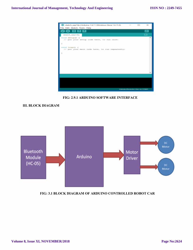
FIG: 2.9.1 ARDUINO SOFTWARE INTERFACE
III. BLOCK DIAGRAM
FIG: 3.1 BLOCK DIAGRAM OF ARDUINO CONTROLLED ROBOT CAR
International Journal of Management, Technology And Engineering
Volume 8, Issue XI, NOVEMBER/2018
ISSN NO : 2249-7455
Page No:2624

3.1 BLOCK DIAGRAM EXPLANATION
In this circuit I have used Arduino Uno board to control the robot car. This car have two dc motors at its front and rear
side. Front side motor is used for giving direction to car means turning left or right side (like real car steering feature).
And rear side motor is used for driving the car in forward and backward direction. A Bluetooth module is used to receive
command from android phone and Arduino UNO is used for controlling the whole system. Bluetooth controlled car
moves according to button touched in the android Bluetooth mobile app. To run this project first we need to download
Bluetooth app form Google play store. We can use any Bluetooth app that supporting or can send data.
3.2 CIRCUIT DIAGRAM
FIG: 3.2 CIRCUIT DIAGRAM OF THE PROJECT
3.2.1 CIRCUIT DIAGRAM EXPLANATION
Bluetooth controlled Robot car is shown in above figure. A Motor driver is connected to Arduino to run the car. Motor
driver’s input pins 2, 7, 10 and 15 are connected to Arduino's digital pin number 12, 11, 10 and 9 respectively. Here we
have used two DC motors to driver car in which one motor is connected at output pin of motor driver 3 and 6 and another
motor is connected at 11 and 14. A 9 volt Battery is also used to power the motor driver for driving motors. Bluetooth
module’s RX and TX pins are directly connected at TX and RX of Arduino. And vcc and ground pin of Bluetooth module
is connected at +5 volt and Ground of Arduino. And a 9 volt battery is used for power the circuit at Arduino’s VIN pin.
International Journal of Management, Technology And Engineering
Volume 8, Issue XI, NOVEMBER/2018
ISSN NO : 2249-7455
Page No:2625
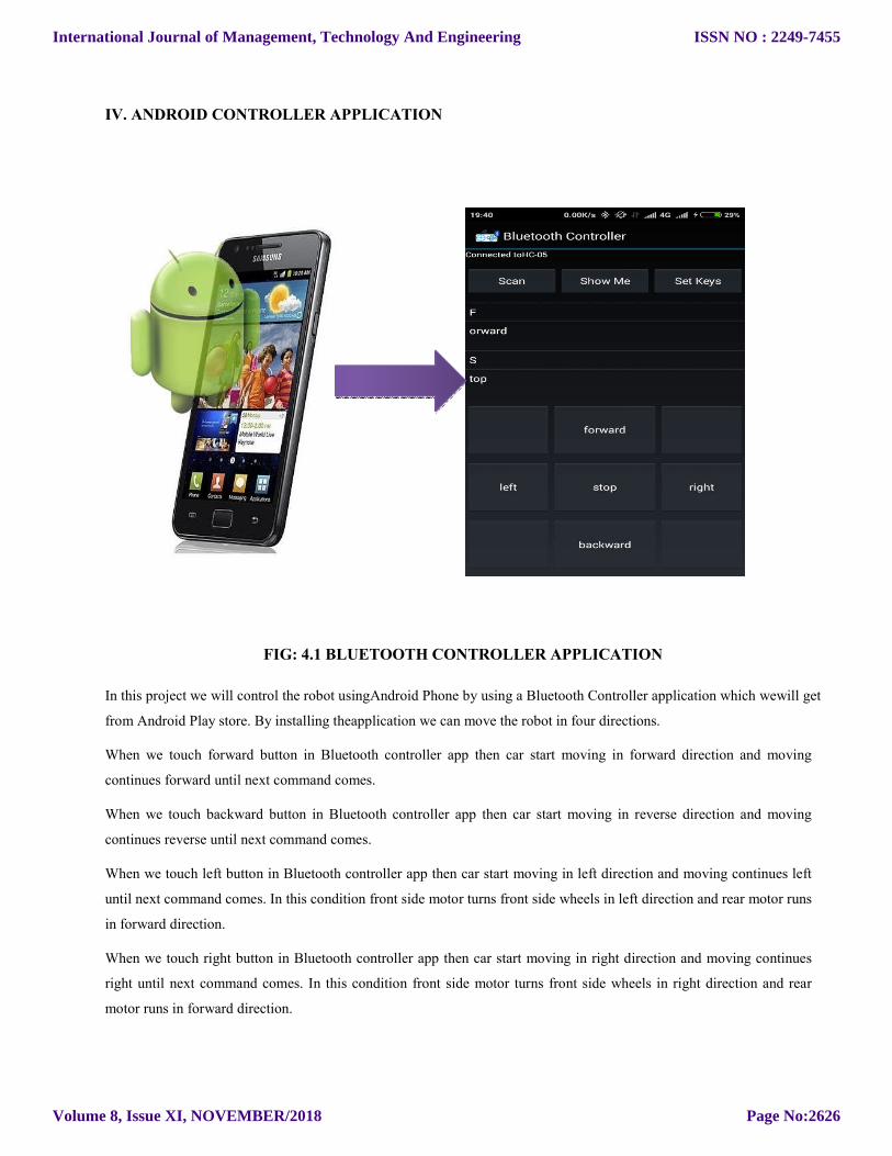
IV. ANDROID CONTROLLER APPLICATION
FIG: 4.1 BLUETOOTH CONTROLLER APPLICATION
In this project we will control the robot usingAndroid Phone by using a Bluetooth Controller application which wewill get
from Android Play store. By installing theapplication we can move the robot in four directions.
When we touch forward button in Bluetooth controller app then car start moving in forward direction and moving
continues forward until next command comes.
When we touch backward button in Bluetooth controller app then car start moving in reverse direction and moving
continues reverse until next command comes.
When we touch left button in Bluetooth controller app then car start moving in left direction and moving continues left
until next command comes. In this condition front side motor turns front side wheels in left direction and rear motor runs
in forward direction.
When we touch right button in Bluetooth controller app then car start moving in right direction and moving continues
right until next command comes. In this condition front side motor turns front side wheels in right direction and rear
motor runs in forward direction.
International Journal of Management, Technology And Engineering
Volume 8, Issue XI, NOVEMBER/2018
ISSN NO : 2249-7455
Page No:2626

4.1.1 FUTURE ENHANCEMENTS
ADVANCED MOTION
Robot arm controlled by servo motor
OBSTACLE AVOIDANCE
Install proximity sensor, develop algorithms to steer around / back up when obstacles detected
VISION
Use camera to transmit frames back to Android application for display to user
Bluetooth too low-bandwidth; switch to Wi-Fi
V.CONCLUSION
This is indeed a cost-effective and efficient project. The novelty lies in the fact that it is a cost-effective project with a
simple and easy to use interface compared to existing ones. Also the Bluetooth RC Controller application is more user
friendly. The robot is small in size so it can be used in spying purpose. With few additions and modifications, this robot
can be used in army for detecting and disposing hidden land mines. The robot can be used for surveillance. In future we
can interface sensors to this robot so that it can monitor some parameters and we can improve the efficiency using Internet
of Things (IOT) technology. We can also add wireless camera, in order to incorporate other security features It is feasible
to implement Bluetooth communication between Smartphone and microcontroller. It can be used in various industries for
picking various objects where human intervention is not desired. On a large scale, it can be used to develop robots with
military applications. It can be used to target enemy without any human being crossing the territory. It provides for more
development of applications based on android operating system. The development of apps for Android in Android SDK is
easy and free of cost. With tremendous smart phone in markets, it is bound to have many more applications in near future.
In this project hardware setup is constructed using Arduino Uno and the programming is compiled in the Arduino IDE
software and finally Robot car is controlled by the Arduino using Bluetooth module.
FIG: 5.1 SNAPSHOT OF BLUETOOTH BASED SMART PHONE CONTROL ROBOT PROJECT
International Journal of Management, Technology And Engineering
Volume 8, Issue XI, NOVEMBER/2018
ISSN NO : 2249-7455
Page No:2627

REFERENCES
[1] Xiaoluet.al. "Robot control design based on smartphone." Control and Decision Conference (CCDC), 2013
25thChinese. IEEE, 2013
[2] Yeon-Gyunkim et.al. "Smartphone-controlled user calling system for a mobile robot."Robotics (ISR), 2013 44th
International Symposium on. IEEE, 2013.
[3] Rouanet, Pierre, et.al. "The impact of human– robot interfaces on the learning of visual objects." Robotics, IEEE
Transactions on 29.2 (2013): 525-541.
[4]TatianaAlexenko et.al. "Android-based speech processing for eldercare robotics." Proceedings of the
companionpublication of the 2013 international conference on intelligent user interfaces companion. ACM, 2013.
[5] M. Young, The Technical Writer’s Handbook. Mill Valley, CA: University Science, 1989.
[6] https://developer.android.com/training/basics/firstapp/index.ht ml
[7] https://www.codeproject.com/Articles/628894/Learn-How-toDevelop-Android-Application
[8] https://www.tutorialspoint.com/android/
[9] http://www.coreservlets.com/android-tutorial
International Journal of Management, Technology And Engineering
Volume 8, Issue XI, NOVEMBER/2018
ISSN NO : 2249-7455
Page No:2628