android and web application for tracking employees
TRANSCRIPT

California State University, San Bernardino California State University, San Bernardino
CSUSB ScholarWorks CSUSB ScholarWorks
Electronic Theses, Projects, and Dissertations Office of Graduate Studies
12-2019
ANDROID AND WEB APPLICATION FOR TRACKING EMPLOYEES ANDROID AND WEB APPLICATION FOR TRACKING EMPLOYEES
Kaival Dholakia
Follow this and additional works at: https://scholarworks.lib.csusb.edu/etd
Part of the Computer Engineering Commons
Recommended Citation Recommended Citation Dholakia, Kaival, "ANDROID AND WEB APPLICATION FOR TRACKING EMPLOYEES" (2019). Electronic Theses, Projects, and Dissertations. 953. https://scholarworks.lib.csusb.edu/etd/953
This Project is brought to you for free and open access by the Office of Graduate Studies at CSUSB ScholarWorks. It has been accepted for inclusion in Electronic Theses, Projects, and Dissertations by an authorized administrator of CSUSB ScholarWorks. For more information, please contact [email protected].

ANDROID AND WEB APPLICATION FOR
TRACKING EMPLOYEES
A Project
Presented to the
Faculty of
California State University,
San Bernardino
In Partial Fulfillment
of the Requirements for the Degree
Master of Science
in
Computer Science
by
Kaival Dholakia
December 2019

ANDROID AND WEB APPLICATION FOR
TRACKING EMPLOYEES
A Project
Presented to the
Faculty of
California State University,
San Bernardino
by
Kaival Dholakia
December 2019
Approved by:
Dr. Ernesto Gomez, Committee Chair, Computer Science and Engineering
Dr. Kerstin Voigt, Committee Member
Dr. Owen Murphy, Committee Member

© 2019 Kaival Dholakia

iii
ABSTRACT
The purpose that this tracking system serves is to keep track of the
employees of the company who have the nature of their job which involves a lot
of traveling to various locations on a day to day basis. It is an amalgamation of
Android as well as a Web application. The employee is supposed to pass the
location and image as per the terms and conditions specified to use the Android
application. The web application is used by the admin department to access the
information which would help them monitor the location of the employee in a
timely manner. The Android application is developed using Native Android on
Android Studio while Visual Studio 2017 is being used for the functioning of the
web application.
iv
ACKNOWLEDGEMENTS
I express my deepest gratitude towards my project advisor and mentor Dr.
Ernesto Gomez for giving me his valuable inputs and guidance throughout the
production of this project. I would like to thank Dr. Kerstin Voigt and Dr. Owen
Murphy for being the committee members and for showing flexibility in terms of
time and work schedule.
I would like to thank my parents for their patience and constant support
during these two years of my educational endeavor.

v
TABLE OF CONTENTS
ABSTRACT .......................................................................................................... iii
ACKNOWLEDGEMENTS .....................................................................................iv
LIST OF TABLES ................................................................................................ vii
LIST OF FIGURES ............................................................................................. viii
CHAPTER ONE:INTRODUCTION
Background ................................................................................................ 1
Purpose ..................................................................................................... 2
Existing System ......................................................................................... 3
CHAPTER TWO:SYSTEM ANALYSIS
Proposed System ...................................................................................... 4
System Requirement Specifications .......................................................... 5
Hardware Requirements ................................................................. 5
Software Requirements ................................................................... 5
CHAPTER THREE:FEASIBILITY REPORT
Feasibility Study…….………………………………………………………......6
Technical Aspect…….……………………………………………….....7
Economic Aspect……..………………………………..………………..8
Operations Aspect………………………………………..……………..9
CHAPTER FOUR:SYSTEM DESIGN
UML Diagrams. ........................................................................................ 10
Use Case Diagrams ...................................................................... 11
Sequence Diagrams ...................................................................... 13

vi
Data Flow Diagrams ................................................................................ 15
CHAPTER FIVE:SYSTEM TESTING
Testing ..................................................................................................... 18
Unit Testing ................................................................................... 19
Integration Testing ........................................................................ 19
System Testing ............................................................................. 20
Validation Testing .......................................................................... 20
Output Testing............................................................................... 20
User Acceptance Testing .............................................................. 21
CHAPTER SIX:OUTPUT SCREENSHOTS ........................................................ 22
CHAPTER SEVEN:FUTURE ENHANCEMENTS
GPS Co-ordinates Buffer Value ............................................................... 42
Password Authority .................................................................................. 42
Internet Connectivity ................................................................................ 42
CHAPTER EIGHT:CONCLUSION ...................................................................... 43
REFERENCES ................................................................................................... 44
vii
LIST OF TABLES
Table 1. USER Login Page Validation………………………………………………24
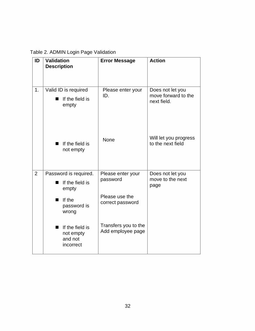
Table 2. ADMIN Login Page Validation .............................................................. 32

viii
LIST OF FIGURES
Figure 1. Admin Use Case Diagram. .................................................................. 11
Figure 2. Employee Use Case Diagram. ............................................................ 12
Figure 3. Admin Sequence Diagram. .................................................................. 13
Figure 4. Employee Sequence Diagram. ............................................................ 14
Figure 5. Level 0 Data Flow Diagram. ................................................................ 15
Figure 6. Level 1 Data Flow Diagram ................................................................. 16
Figure 7. Level 2 Data Flow Diagram ................................................................. 17
Figure 8. Welcome Page. ................................................................................... 22
Figure 9. Sign-up Page. ...................................................................................... 23
Figure 10. Camera Access. ................................................................................ 25
Figure 11. Image Captured. ................................................................................ 26
Figure 12. Send Image Page. ............................................................................. 27
Figure 12.1. GPS Screen ................................................................................... 28
Figure 14. Data Transfer Notification. ................................................................. 29
Figure 15. Logout Functionality. ......................................................................... 30
Figure 16. Admin Login Page ............................................................................. 31
Figure 17. Add Employee Page. ......................................................................... 33
Figure 18. Check Location Page ........................................................................ 34
Figure 19. Location Check Functionality. ............................................................ 35
Figure 20. Location Check Functionality II. ......................................................... 36
Figure 21.View Image Page. .............................................................................. 37

ix
Figure 21.1. View Image Layout. ........................................................................ 38
Figure 23. Change Password Page. ................................................................... 39
Figure 24. View Employee Page. ....................................................................... 40
Figure 25.Logout Functionality. .......................................................................... 41

1
CHAPTER ONE
INTRODUCTION
Background
Companies around the world have a number of employees serving them and
each company would like to have knowledge of the output that their employees are
providing which can be the only means to determine productivity. Different companies
may have multiple methods to keep track of their employees and also to monitor the
work that they provide and also the means of keeping track of productivity may vary for
every company on the basis of the nature and requirement of the company. This system
could serve more than a single purpose for any company existing in the market using it.
It could be said that the system could be much more useful for the work-places or
work structures that would include extensive travelling by the employees. Many would
also argue that the system can be useful only for marketing professionals who have
extensive travel as a part of their job functionalities. But the system has a dynamic
nature to itself where the system could be made functional according to the requirement
of the company. It also helps the admin department of the company to have an easier
way towards generating the payroll of the employees due to the clock-in/clock-out
feature.

2
Purpose
The purpose that this system serves is that it makes monitoring the location of
the employees very straightforward. Due to the clock-in/clock-out feature, attendance
monitoring of the employees also becomes very easy for the admin and the HR
department for monitoring the salary payroll of any particular employee.
Because the company makes it mandatory for each and every employee to use
the system on a day to day basis, it saves a lot of time and energy solving attendance
and pay-roll issues. And because the system has a specific employee ID for each
employee, it is practically impossible to forge attendance by any of the employees. It
also needs the employee to stay at a particular status which again works as a security
against forgery on attendance. This is the basic purpose of this particular system so that
it can be universally used in the corporate world and could be a solution to a lot of
problems which the employers currently face.
Existing System
In the current scenario, there is no such web or mobile application which would
track an employee to check whether he/she is at the location that he/she is supposed to
be. The ADMIN/HR department who is responsible for maintaining a proper work
structure could check on the output and productivity of each employee that is working.
Till now the ADMIN department would find it impossible to find the location of any of the
employees, which could also lead to forged attendance. The only way that the
HR/ADMIN department could find a rough estimation of the location of any of the
employees is to contact the employee is telephonically. This means of communication,

3
by many companies, would not be believed to be reliable. Because the chances of
getting a false location is this means of communication is believed to be much higher.
Thus ,an upgrade in the current work system is much required and this system serves
aptly for determining the desired employee location.

4
CHAPTER TWO
SYSTEM ANALYSIS
Proposed System
It would be recommended to use an amalgamation of RESTful web services
which can be used accordingly for serving the requirements of the end users
dynamically. A recursive algorithm should be used. Compile and run function can be
executed once the below mentioned software requirements are fulfilled. The
requirement of the version is 2.2. The requirement that has been specified is a minimum
and any version above can be brought into use but using any version below is not
permissive. This system has been made to use CAAS based RESTful web services. It
gets hosted by real time server each time it gets executed. The employee having the
android device is presumed to be clocking in and clocking out on a daily basis. This
practice would be the only medium which would be taken into account while marking
his/her attendance, so it becomes mandatory for every employee. As the application
has started, it would run continuously and would provide the location of any employee to
the server through specific GPS co-ordinates. These GPS co-ordinates can be checked
upon by the ADMIN department with the help of a web application which has been
made accessible to them. The system has a functionality where the system camera
opens up and the user is supposed to take an image of him/herself in order to proceed
ahead in the android system in order to clock-in.

5
System Requirement Specifications
This project will consist of a development phase and a production phase (prototype) that
requires the following hardware and software requirements.
Hardware Requirements
• Laptop or PC
1) I7 processor
2) 1GB RAM(minimum)
3) 5GB Hard Drive
• Android Phone or Tablet
1) Processor: 1.2 Quad core or higher
2) 1GB RAM
Software Requirements
1) Laptop or PC
a) Windows 7 or above
b) MySQL 2008
c) ADK and ASP.NET
2) Android Phone or Tablet
a) Android version 5 or above

6
CHAPTER THREE
FEASIBILITY REPORT
Feasibility Study
While working on any project, singularly or in a team, it is very important to create
a feasibility report on various aspects so that it could be determined whether investing in
the project, financially or professionally, worthy enough? There are certain aspects that
need to be taken into consideration like:
• What problems could arise?
• Is there a solution to these problems?
• Is the solution optimum?
The most popular aspects taken into consideration are technical, operational and
economic. Feasibility study is always based on the proposed system and to develop a
better understanding of the future product. The below mentioned feasibilities should be
taken into consideration in order to ensure that the execution and the running of the
product is smooth and the client and the developer has to face minimalistic problems
with readily available optimal solutions.
In this chapter, we study about the economic, operational and technical feasibility
of the new version of the already existing project which is also addressed here as the
proposed system. The feasibility study based on these three main factors are as
follows.

7
Technical Aspect
Technical feasibility is one of the most important aspects for understanding the
prospects of the project that is supposed to be made. It helps the developer foresee that
the technologies required for implementing the project are already available, or they
need to be developed which would also mean an increase in costs, affecting the
economic feasibility.
This aspect also determines whether the technologies and skills required to use
the technologies to develop the project is already is access to the organization. The
system can be told to be feasible if the following requirements are met:
➢ The technologies required to implement and execute the system
➢ Whether the system can be updated for constant changes
➢ The system should be accurate, reliable and secure
➢ This system should be easily accessible for easily fixing the problems that
may arise during development phase
All these factors must be considered and if these factors have a positive
Outcome, then the system could be safely said to be feasible for development and
usage of the project.
Operating system: Windows 7 or above
Language: ASP.Net with C# and Android Development Toolkit
Database: MySQL

8
Economic Aspect
Economic feasibility is also one of the aspects that need to be taken into
consideration, while developing and implementing any project. For this particular
system, it could be safely concluded to be feasible as it requires no extra investment
and has been completed within 3 months.
In this phase, we did a lot of comparisons among different projects on the basis
of investment that we needed to put in. The project which was more beneficial was
selected for putting into execution. The means by which generally the feasibility of a
project is tested is the amount of financial benefits that can be obtained. If the financial
benefits obtained from the project are more than the investments made in building it, it
could be said to be economically feasible. A project can be considered feasible if it
incurs a profit or at least covers the cost of building and implementing the project. For
addressing this issue, the following aspects should be considered:
➢ The cost of building the entire project
➢ Hardware and software costs
➢ Android Development Toolkit costs
➢ Maintenance costs
As the above mentioned points have a positive outcome when considered, our
project passes this particular feasibility test and is well supported by many investors.
Operational Aspect
This is the third and the final aspect while creating a generalized feasibility report.
The Operational aspect consists of factors such as time taken to finish the project, the

9
number of people who had to participate in completion of the project etc. The project
which uses the least amount of resources is the solution which should be accepted as it
is the most feasible when compared to others which would use more resources. The
following points should be considered before declaring the project operationally feasible:
➢ The work ethic and the process of obtaining the results, implementing the
code and executing the project should be universally accepted.
➢ The proposed system should not cause any problem while presenting it to
the end-users and should be implemented properly.
This particular project is operationally feasible as the time constraints and
operational aspects are met, and taking into consideration the other aspects, this
project can be said to be feasible in a general sense.

10
CHAPTER FOUR
SYSTEM DESIGN
UML Diagrams
Use Case Diagrams
Use Case diagrams are the set of diagrams which show us that what different
kind of the system has to offer. It shows us all possible access that the system provides
to users. The behavior of different and all kinds of users has to be taken into
consideration while creating use case diagrams. A good way to develop optimized use
case diagrams which would be able to provide all possibilities without replication is to
create separate cases for different uses that it may provide and integrating them all into
one diagram for a single user. There can be multiple use case diagrams depending on
the number of different roles, users are supposed to perform. Use case diagrams are
mostly used for the documentation part of any project and it helps you understand the
specific usage details and can answer queries if the user is facing any problems while
operating the system. The Use Case Diagrams also need to be updated if any changes
are supposed to be made to the system.
The system can have many users and these users are mostly referred to as
Actors. There can be more than one of these as mentioned above. The end-users of the
system are represented as actors. This system in particular has two users: Admin and
Employee

11
Use Case Diagram
ADMIN
Figure 1. Admin Use Case Diagram.
Open the website
Login
Search with Employee ID
Can Track the Employee Can Check the attendance
Can see employee location
Is responsible for data security

12
Employee
Figure 1. Employee Use Case Diagram.
Access the Application
Login as Employee
Face capturing
Turn on GPS
Sends GPS data to server
Goes to the desired location
Logout from application

13
Sequence Diagram
ADMIN Enters ADMIN id& Password
Validates ADMIN Invalid Login
- - - - - - - - - - - - - - - - - - - - - - - - - - - - - - - - - -
If Valid, then Displays Main page
Checks for the new user
Retrieves the list of new Users
Checks/search for Employee details
Retrieves the list of Employee details Tracks Employees attendance and location
Manages all security related issues
Figure 3. Admin Sequence Diagram.
Web Service Based Android Tracking
Main Page

14
Employee Enters Emp id & Password Validates Employee Invalid Login
- - - - - - - - - - - - - - - - - - - - - - - - - - - - - - - - - -
New Registration If Valid, then Displays Main page Face Capturing Turn on GPS Sends GPS Data to Server Goes to the desired location
Logs out from Application
Figure 4. Employee Sequence Diagram.
Web Service Based Android Tracking
Main Page
15
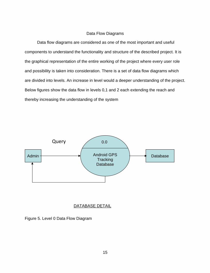
Data Flow Diagrams
Data flow diagrams are considered as one of the most important and useful
components to understand the functionality and structure of the described project. It is
the graphical representation of the entire working of the project where every user role
and possibility is taken into consideration. There is a set of data flow diagrams which
are divided into levels. An increase in level would a deeper understanding of the project.
Below figures show the data flow in levels 0,1 and 2 each extending the reach and
thereby increasing the understanding of the system
Figure 5. Level 0 Data Flow Diagram
Android GPS
Tracking Database
0.0
Admin Database
DATABASE DETAIL
Query

16
Figure 6. Level 1 Data Flow Diagram
Request
1.0
Admin
Query Request
Database Access User gets Access
User Reqiurement
Process Database
Data Access
1.1
17
Figure 7. Level 2 Data Flow Diagram
Accept
2.0
Admin
Available resource check
Implement
Process request to user
Android GPS WebService Database
Database Information 2.
1
2.22
Query
18
CHAPTER FIVE
SYSTEM TESTING
Testing
The testing phase is one of the most important phases in the software development life-
cycle. For any project, be large or small scale, the testing phase holds utmost
importance as it is the only means by which the developer can make sure that all the
user requirements are served and in proper function. This particular system has been
developed using C# for scripting of the web application and Android Development
Toolkit for developing the mobile application. Even the applications that are claimed to
be erroneous in nature have been tested before being deployed. Every possibility of
every input gets tested before coming to any kind conclusion and after the desired
output is achieved, the project is termed to be successful. Not only the output of the
system, but also the flow of data through the entire system also gets tested. The main
objective of the testing phase in the software development life-cycle is to make the
entire project successful and also keep room for the project to update from time to time
for allowing an increase of ease of using the system for any user. Hence, the testing
phase, being one of the later phases of the software development life cycle, becomes
one of the most important phases for the development of any system.
The testing phases divided into six types:
1) Unit Testing
2) Integration Testing
19
3) System Testing
4) Validation Testing
5) Output Testing
6) User Acceptance Testing
Unit Testing
Unit Testing is the most basic type of testing and one of the types by which the
testing phase gets initiated. Each and every module of the project gets tested
separately and each output gets monitored. This phase is called Module testing. This
testing as the name suggests tests each and every module and gets implemented
during the development phase by the individual who actually develops the code. In spite
of this testing being performed majorly by the developer, there is a certain amount of
time dedicated to this type of testing.
Integration Testing
Integration testing is the one which needs to be conducted after unit testing.
Even after each and every unit gets tested individually, they need to get tested
integrated to each other. When the previously tested modules get together into a
structure, integration testing can be conducted. Integration testing is the first systematic
part of the testing phase,it is the only part where, as the name suggests, the individual
modules get integrated. As a part of integration testing, the system interface also gets
tested with the requirement to integrate all the modules
20
System Testing
System testing is the third part of the testing phase. The system testing is a very
important requirement when it comes to testing as it is the means to test how well the
system can adapt to any new situation. This part of the testing phase also becomes
very important as it shows us how compatible or adaptive the system can be when
projected live. It is also assumed that if every section of the system is working
harmoniously, the system test can be called successful.
Validation Testing
This part is the next to the system testing part of the six-part testing phase. As
the modules get tested individually, get integrated and the errors or problems that can
supposedly occur are solved, the final section of the testing phase begins. Either the
system performs according to certain requirements or it creates a list of things that still
need to be addressed. The system in this scenario has been validated and seems to be
working according to specific details.
Output Testing
This section, as it should, comes after the validation testing for the system has
been successfully performed. After the system is validated, and said to be working
appropriately, every output of the system as a whole is supposed to be tested. Every
output of this system is judged in two parts. During the testing, the output on the screen
is given as much importance as the output on paper. When both the output forms are
such that the user gets satisfied, this part of the testing phase is said to be complete.
The output testing of the concerned system has been performed with satisfactory
results.

21
User Acceptance Testing
The final part of the testing phase is the User Acceptance testing. This is where
the system gets tested as a product and it is the real audience that come into contact
with the product. It gets constantly monitored and any changes that seem necessary to
the user are provided in the form of updates.

22
CHAPTER SIX
OUTPUT SCREENSHOTS
The project has been tested completely using all of the above types of testing.
The output of the project is as per expectations and the screenshots are shown below.
Figure 8. Welcome Page.

23
Figure 9. Sign-up Page.
Figure 9 shows the sign-up page that every new user (students only) must first fill out in
order to create an account before using the system.

24
The table below shows which fields in the sign-up page are being checked for data
input.
Table 1. USER Login Page Validation.
ID Validation
Description
Error Message Action
1. Valid ID is required
◼ If the field is empty
◼ If the field is not empty
Please enter your ID.
None
Cursor stays in the field
and user enters ID.
Cursor moves to the
password field.
2. Password is required.
◼ If the field is empty
◼ If the password is wrong
◼ If the field is not empty
Please enter your last name.
Please enter the correct password None
Cursor stays in the field
and user enters last
name.
Stays in the field
It allows the user access
the mobile application

25
Figure 10. Camera access.

26
Figure 11.Image Captured.

27
Figure 12. Send Image Page.
28
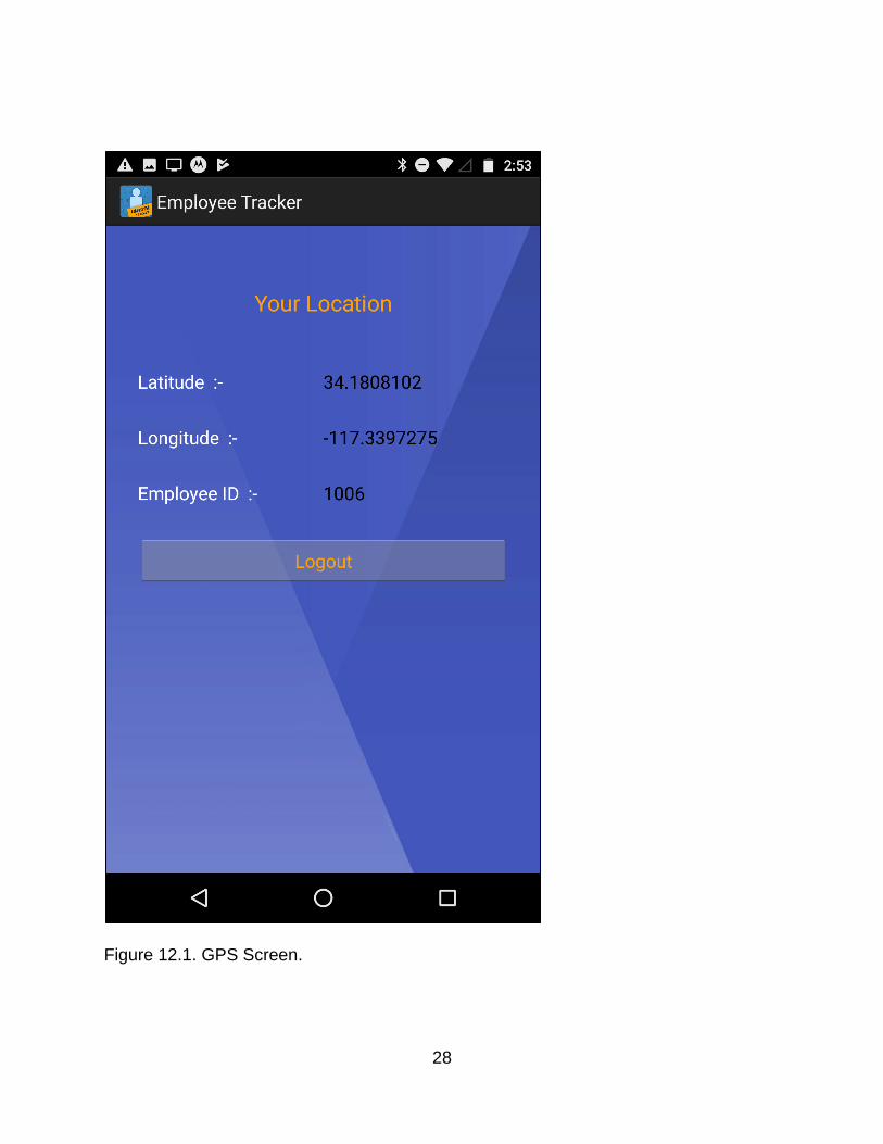
Figure 12.1. GPS Screen.

29
Figure 14. Data transfer Notification.
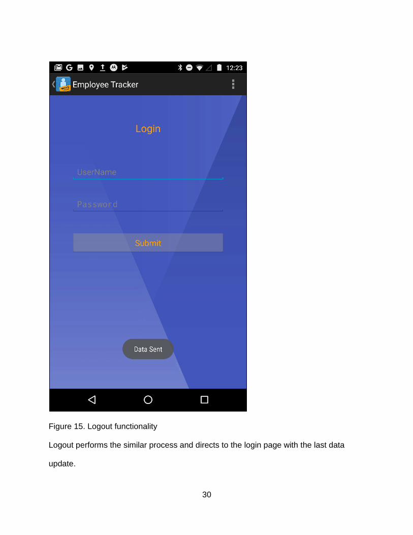
30
Figure 15. Logout functionality
Logout performs the similar process and directs to the login page with the last data
update.

31
Figure 16. The Admin Login Page.
32
Table 2. ADMIN Login Page Validation
ID Validation Description
Error Message Action
1. Valid ID is required
◼ If the field is empty
◼ If the field is not empty
Please enter your ID.
None
Does not let you move forward to the next field.
Will let you progress to the next field
2 Password is required.
◼ If the field is empty
◼ If the password is wrong
◼ If the field is not empty and not incorrect
Please enter your password Please use the correct password Transfers you to the Add employee page
Does not let you move to the next page
33
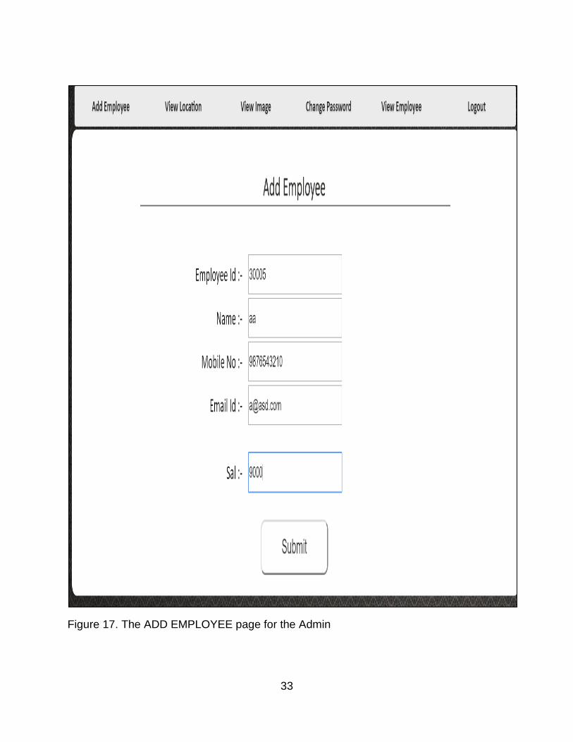
Figure 17. The ADD EMPLOYEE page for the Admin
34
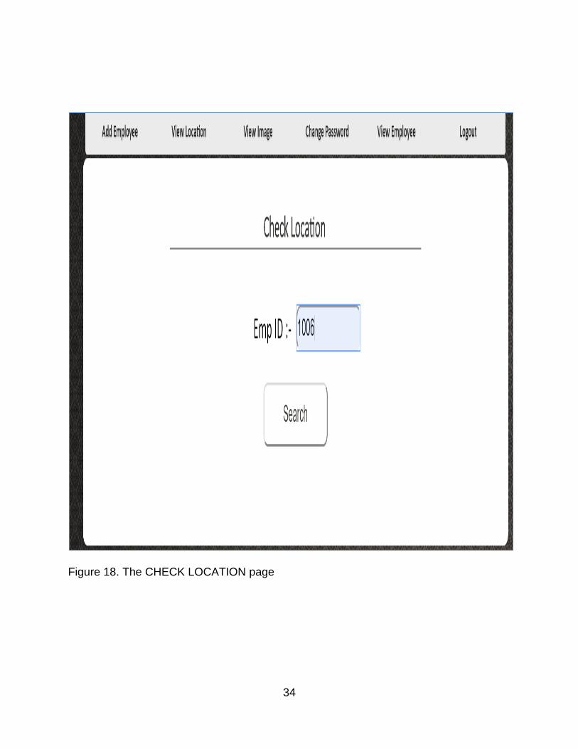
Figure 18. The CHECK LOCATION page

35
Figure 19. Location Check Functionality
The location check which opens up the location on a map and gives you the option to
open up different locations that the employee has been to during the day.
36
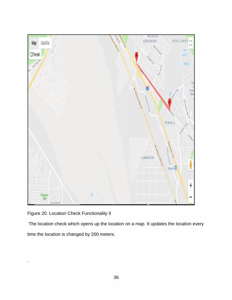
Figure 20. Location Check Functionality II
The location check which opens up the location on a map. It updates the location every
time the location is changed by 200 meters.
.

37
Figure 21. The VIEW IMAGE page This page has a similar kind of approach as the view location page. The ADMIN can
select the image and click on show to view the image at different times. The image can
be seen at the bottom of the page. Only one image is accessible at one time.

38
Figure 21.1. The VIEW IMAGE LAYOUT
Figure 21.1 is an extension of the view image page. The above image shows how the
image is accessible to the ADMIN
39
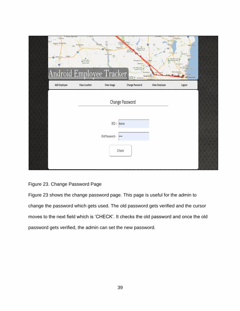
Figure 23. Change Password Page
Figure 23 shows the change password page. This page is useful for the admin to
change the password which gets used. The old password gets verified and the cursor
moves to the next field which is ‘CHECK’. It checks the old password and once the old
password gets verified, the admin can set the new password.

40
Figure 24. View Employee Page.
Figure 24 displays the list of employees that have been provided access to the
application. The user information gets displayed. The information that gets displayed is
exactly the same as the information entered by the admin at the ADD EMPLOYEE
section.

41
Figure 25. Logout Functionality
Figure 25 displays the functionality of the Logout Button. It simply logs the admin out of
the system

42
CHAPTER SEVEN
FUTURE ENHANCEMENTS
GPS Co-ordinates Buffer Value
As of now, the buffer between of the location of the employee according to the GPS co-
ordinates and the actual location of the employees is about 45 feet. This means that
there will be no change in the co-ordinates of the employee location even if there is a
change in the employee location which might be less than 45 feet. In future, these co-
ordinates can be worked upon.
Password Authority
The password that needs to be used by the user(in this case: the employee) is set by
the admin who creates the user profile and the same password needs to be used by the
user each time. This system needs a change as the password can be used to forge the
location
Internet Connectivity
This system currently needs internet connection for detecting the location of the
employee. In the future, it would be very helpful if the system can detect the location
without the need of internet access. It could be useful in case where the employee
travels to a location where no internet access is available.
CHAPTER EIGHT

43
CONCLUSION
This system could be useful at a universal level. It can be used among any of the
companies of the word for tracking the location of the employees and especially for the
employees who work in the field of marketing. As the feature of clocking in and clocking
out is also included, it also helps the ADMIN department run the payroll services. It also
helps the ADMIN department to mark and monitor the attendance of the employees.
Being enrolled in this system also makes the chances of forgery very much impossible
for any of the employees.
In conclusion, it could be safely said that the system delivers satisfactory results
and can be very useful for any of the companies who may face trouble managing the
details of the employees and also could be commercially useful for the developer as it
could be sold to multiple companies.

44
REFERENCES
1) Microsoft Developer Network (MSDN): http://msdn2.microsoft.com/en-
us/default.aspx: This is a valuable online resource, and is a must for any developer
using Microsoft tools.
2) Microsoft ASP.NET :http://www.asp.net/.This is the official Microsoft ASP.NET web
site. It has a lot of: tutorials, training videos, and sample projects.
3) IEEE:http://ieeexplore.ieee.org/xpl/articleDetails.jsp?tp=&arnumber=6726550&query
Text%3Dandroid+web+service
4) IEEE:http://ieeexplore.ieee.org/xpl/articleDetails.jsp?tp=&arnumber=6762971&query
Text%3Dandroid+web+service