andreas bamberger, uwe renz, andreas zwerger *[email protected] hubert blank, christoph...
TRANSCRIPT

Andreas Bamberger, Uwe Renz, Andreas Zwerger
Hubert Blank, Christoph Brezina, Klaus Desch, Jochen Kaminski, Thorsten Krautscheid, Walter
Ockenfels, Martin Ummenhofer, Peter Wienemann, Simone Zimmermann

• Spatial resolution and understanding of possible systematics
• Time resolution and time walk correction
• Software issues -> Pixelman PlugIns
Apr 18, 2023 2

Apr 18, 2023, Amsterdam 3
• Charged particle ionizes the chamber gas • The primary charge drifts along the electric
field E towards the end plates• Magnetic field parallel to E reduces
transverse diffusion and allows measurement of the particle momentum
• At the end plate the primary ionization is amplified
• Readout of the signal
Time Projection Time Projection Chamber TPCChamber TPC
• Micro Pattern Gas Detectors (MPGD): high resolution readout and high
rates• Pixilated readout offers high resolution
Digital Bubble Chamber • A TPC at the ILC needs excellent
momentum resolution GEM-TimePix for end plate readout
region of interest for this talk

4
F. Sauli, Nucl. Instrum. Methods A386(1997)531F. Sauli, Nucl. Instrum. Methods A386(1997)531F. Sauli, http://www.cern.ch/GDDF. Sauli, http://www.cern.ch/GDD Thin, metal coated polymer Thin, metal coated polymer
foil. Very high density of foil. Very high density of chemical pierced holeschemical pierced holesPrinciple:
• 2 layers Cu each 5µm thick, separated from each other by 50µm Kapton.
• Conical etched holesholes largest Ø70µmØ70µm,, diagonal distance of holesdistance of holes 140µm140µm.
Advantages of Triple-GEM-setupAdvantages of Triple-GEM-setup Gas gain up toGas gain up to 101055 in ArCO2 easily achievable Minimizing the back drift of positive ions into Minimizing the back drift of positive ions into
the drift volume (the drift volume (OO(10(10-2-2)))) Encapsulated region of amplificationEncapsulated region of amplification
Apr 18, 2023, Amsterdam

5
TimePix properties inherited from TimePix properties inherited from MediPixMediPix Pixel size 55µm in a 256x256
Matrix dimensions of the sensitive areasensitive area: 1,4x1,4cm1,4x1,4cm22 lower threshold of 700 e-
-
X.
Llo
part
Cu
die
, “D
esig
n A
nd
C
hara
cte
riza
tion
Of
64-K
Pix
els
Ch
ips
Work
ing
In
Sin
gle
Ph
oto
n P
rocessin
g
Mod
e”,
CER
N-T
HES
IS-2
00
7-0
62 1,4cm
TimePixTimePix Based on improved design of MediPix2 MXR Time Time informationinformation on each pixel,on each pixel, due to an
adjustable clock up to ≈100MHz, distributed to all pixels
The 2 different modesThe 2 different modes out of four available modes are used: Time over threshold TOT- Time over threshold TOT- (amplitude recontruction) (amplitude recontruction) and TIMETIME-mode
modes individually selectablemodes individually selectable for each pixel Mixed Mode important feature for walk
correction
charge-sensitive-input
Apr 18, 2023, Amsterdam
6
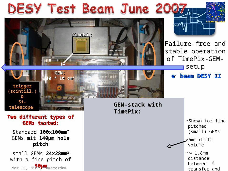
ee-- beam DESY II beam DESY IIGEM:GEM:10 * 10 cm10 * 10 cm22
TimePixTimePix
trigger (scintill.) &
Si-telescope
Failure-free and stable operation of TimePix-GEM-setup
Two different types of Two different types of GEMs tested:GEMs tested:
Standard 100x100mm2 GEMs mit 140µm hole
pitch
small GEMs 24x28mm2
with a fine pitch of 50µm50µm
GEM-stack with GEM-stack with TimePix:TimePix:
•Shown for fine pitched (small) GEMs
•6mm drift volume
• 1.8mm distance between transfer and induction gaps
Apr 18, 2023, Amsterdam

7
• Two independent data streams: TimePix data (Windows based readout) and SiTel.
• Si-Tel allows the determination of the drift distance with ~50μm precision
• Cleaning up of multiple tracks by– double hits in the SiTel– in projection along the track: secondary
maxi-mum signals another track • Every other pixel in a row is set to the TOT
property, and TIME property in between• All over the surface ordered in a checker board
fashion• Reconstruction is done by mapping ½ of all
pixels onto 256x256 matrix. Missing neighbors in TOT or TIME data are thereby interpolated
TOT TIME TOT
TIME TOT TIME
TOT TIME TOT
Apr 18, 2023, Amsterdam

8
1. Search contiguous areas for cluster reconstruction2.2. Use TOT-information to separate merged clustersUse TOT-information to separate merged clusters
BUT diffusion smears our information of individual BUT diffusion smears our information of individual primary eprimary e- - from distinct clusters. These electrons from distinct clusters. These electrons overlap and appear to belong to the same overlap and appear to belong to the same (single) cluster.(single) cluster.
1.5
ns
merged cluster
14mm
Apr 18, 2023, Amsterdam

A. Bamberger 9
1. hole of the first GEM is “perfectly mapped onto the detector. The centroid of the e- avalanche remains stable.
2. for large drift distances Rdiff >>Rcharge, then centroid determination is perfect, even for multi electron clusters
3. for small drift distances is Rdiff <<Rcharge and Rdiff < dhole there is also a perfect mapping for isolated clusters (single or multi electron clusters)
4. for intermediate drift distances Rdiff <<Rcharge and Rdiff > dhole then its not any more perfect for multi-electron clusters
dri
ft d
ista
nce
z
amplification volume
Rdiff
Rcharge
dhole
3 length scales: charge radius Rcharge, dhole, transv. diffusion Rdiff(z)
pixel detector surface Apr 18, 2023, Amsterdam

10
• The clusters are arranged in a line along the track and produce overlapping charges
• It depends on the direction considered for the precise mapping: rectangular to the track it may stay precise and reveal the hole structure
• the position of the centroids along the track is not necessarily mapping the cluster position because of overlapping charge distributions
precision of hole mapping is maintained in transv. direction
track
charges
GEM holes
precision of hole mapping lost along the track
Apr 18, 2023, Amsterdam

11
beambeam
“old” orientation “new” orientation
x
z
Rotate GEM by 90°Rotate GEM by 90°
120µ
m
70µ
m
As structure of 120µm visible in FFT
Now 70µm projected hole pitch
140µ
m
Apr 18, 2023, Amsterdam

12
No Signal
• Use Fast Fourier Transformation (FFT) periodic structure at 1/8.39mm corresponds 119μm, independent of sampling rate (number of supporting points of the FFT).
• No such structure seen for drift distances > 1mm seen. This structure is smaered by transverse diffusion
• After rotation by 90°: signal in FFT vanishes
• Signal amplitude depends on orientation Chip vs. GEM
„new“ orientation (rotated by 90°)
„old“ orientation
„old“ orientation
FFTFFT
Apr 18, 2023, Amsterdam

13
1 mm
signal disappears with• rotation of the coordinate
system with respect to the TimePix frame α <-9 andα > 9 mrad
• “fortuitous” peak at α near zero (GEM almost coincides with the chip’s orientation)
• the signal strongly depends on the drift distance z
Reason: the disappearance is due to the fact that the transverse diffusion smears out the structure Rdiff > dhole
..≥2 electron cluster
2 mm
Apr 18, 2023, Amsterdam

14
• does the orientation of the track matter with respect GEM for the point resolution given by the centroids of the clusters?
• Eventually yes, if most of the tracks would run parallel to the holes
• however most tracks are inclined αtrack ~ (22±6) mrad i.e. far from zero
Apr 18, 2023, Amsterdam

15
old GEM configuration with 120 µm projected z-pitch
new GEM configuration with 70 µm projected z-pitch
2 µm 2 µm improvement for improvement for σσ0 0 only through only through rotating the first rotating the first GEM by 90°GEM by 90°Apr 18, 2023, Amsterdam

16
Guard rings on both sides
Active surface 28x24mm28x24mm22
•Referenced outer hole diameter in copper 30µm.
•Inner hole diameter in the Kapton between 17µm-21µm.
•Diagonal hole pitch 50µmDiagonal hole pitch 50µm
•Projected in x 43µm
•Projected in z 25µm
z
x
Apr 18, 2023, Amsterdam

17
Small GEMs Small GEMs improve improve oo by by 5µm. 5µm.
Driftlänge y [mm]
Still possible systematics ?it is a delicate range since the fit function has an infinite slope here …there are events below the drift region…

18
• interpolation of TOT and TIME produces 2 sets of data on each pixel
• for any pixels the time walk can be large
• take maximum in TIME and TOT for the correction. In this case at TOT = 180 the correction amounts to +2.7 counts to be close to the asymptote, where all clusters should lie.
selected cluster
010522 9310526 13910526 16710527 18610527 17010526 11810522 35 0
original data for central column in MM
TOT range for this cluster
asymptote
10 counts
correction
Apr 18, 2023, Amsterdam

19
•Select a column near the centroid of the cluster
•Fit 2nd order polynomials to the TIME and TOT distributions, look for maxima
•Time walk correction done only by the maxima of fits
•Time correction with an exponential function
for this run A = 24, B = 81
max /max
tot Bcorrt TIME Ae
Apr 18, 2023, Amsterdam

20
Similar results from the 48 MHz data (2006) operation: σtime about 12 ns
Apr 18, 2023, Amsterdam
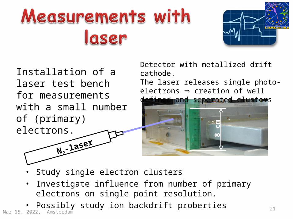
• Study single electron clusters• Investigate influence from number of primary electrons on
single point resolution.• Possibly study ion backdrift proberties 21
8cm
N2-laser
Installation of a laser test bench for measurements with a small number of (primary) electrons.
Detector with metallized drift cathode.The laser releases single photo-electrons creation of well defined and seperated clusters
Apr 18, 2023, Amsterdam8 c
m

22•Work on technologies for post processing chips
• Optimization of readout granularity
originally processed
55x55µm55x55µm22 110x110µm110x110µm22
Pixel acitvePixel passivated
Pixel size 110x110µm2
Pixel size 55x55µm2
Fe55-Cluster
Clusters are partly filled. Possible reason for this:
•Insufficient thickness of passivation
•Crosstalk on chip level
Apr 18, 2023, Amsterdam

23
http://aladdin.utef.cvut.cz/ofat/others/Pixelman/img/arch.png
Pixelman architecture
Interface Pixelman through a dynamically linked library (DLL)
All basic functions of the Pixelman Software are hardcoded and cannot be changed by the user. The source code is not available.
Apr 18, 2023, Amsterdam

• Pixelman is Windows based• Pixelman is written in C++
one is obliged to use the Microsoft Foundation Classes (MFC) which wrap the Windows®Application Interface (API) into a more user- friendly class architecture
• However today‘s Windows developer use the .NET framework (CLR). This is „incompatible“ with Pixelman.
MFC is already a kind of old fashioned
24Apr 18, 2023, Amsterdam

25
First plug-in was a kind of „toy“ plug-in to gain experience. But be warned - as it turns out it is not so straight forward to implement a Graphical User Interface (GUI) into a DLL. But the Prague people from IEAP were a great help, special thanks to M. Jakůbek.
Socket Server Plug-In, written by L. Tlustos
More „mature“ Plug-In for step motor control

26
...or the question how can we manage on a reasonable (short) time scale to have a Linux based DAQ steering at least basic Pixelman functions, e.g. Start/stop???
Can Linux and Windows be „friends“?
Apr 18, 2023, Amsterdam
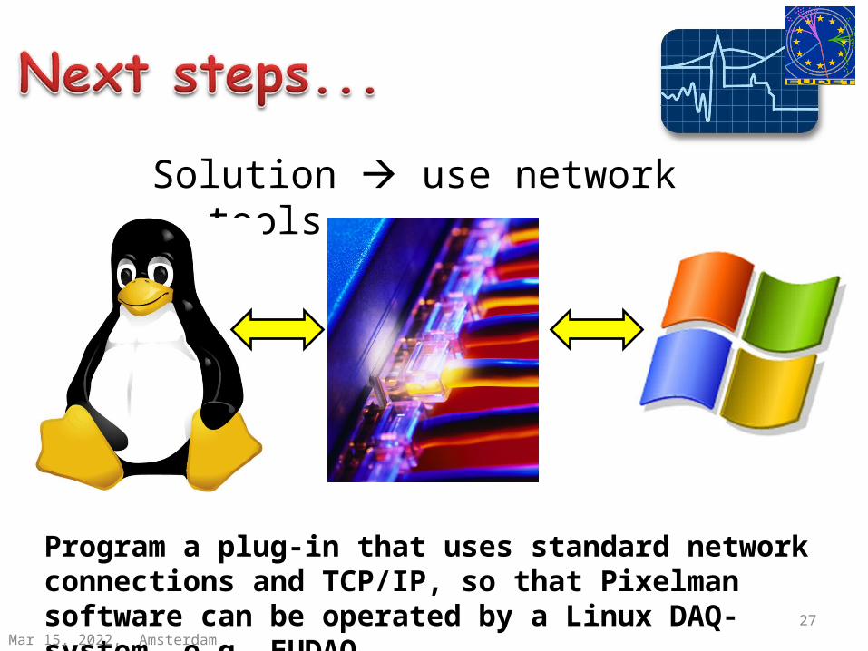
Solution use network tools
27
Program a plug-in that uses standard network connections and TCP/IP, so that Pixelman software can be operated by a Linux DAQ-system, e.g. EUDAQApr 18, 2023, Amsterdam
28
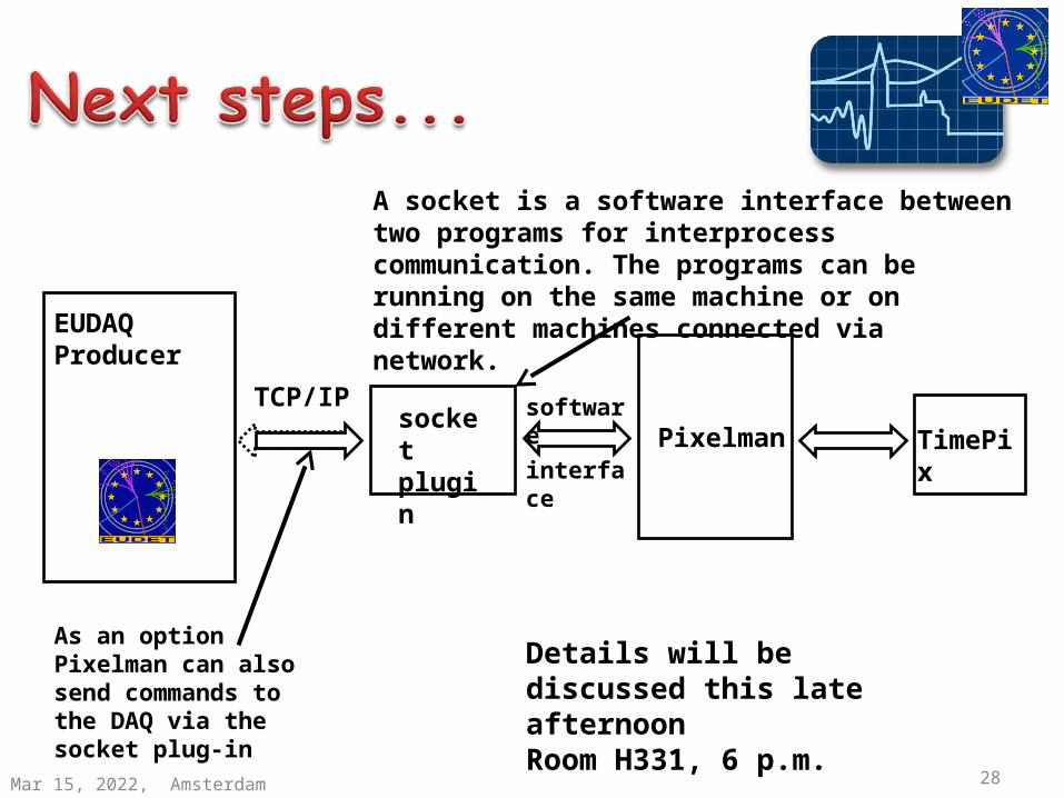
EUDAQProducer
TCP/IPsocketplugin TimePixPixelman
As an option Pixelman can also send commands to the DAQ via the socket plug-in
software
interface
A socket is a software interface between two programs for interprocess communication. The programs can be running on the same machine or on different machines connected via network.
Details will be discussed this late afternoonRoom H331, 6 p.m.
Apr 18, 2023, Amsterdam

• Superb spatial resolution of 20-24 µm• Time resolution of 8ns after corrections for
time walk• -> z resolution of ~0.5mm in typical TPC
gases• First successful test of pixel with enlarged
pixels of 110x110µm2
• Reliable operation of TimePix/GEM setup without any special „protective“ „add-ons“
29Apr 18, 2023

• Finalizing setup of laser test-bench, which could be interesting also for other EUDET partners
• Developing software tools for integration with other DAQ systems and slow control
• BUT everybody is looking forward to a first test beam at DESY -> so focus man power and give a good show
Apr 18, 2023 30

31
• after rotation by 90° the observed spatial signal from the GEM pitch vanishes
• effect on the resolution is an improvement of ~ 2 μm
5 6 7 8 9 100
10
20
30
40
50
after rotating the GEM no periodic structure is seen anymore
y = 0 mm - 1 mm
am
plit
ud
e [n
um
be
r o
f e
ntr
ies]
TimePix x [mm]
FFT
signal spatial
expected signal
Apr 18, 2023, Amsterdam

32
Pixellated readout on Pixellated readout on central electrodecentral electrode
Interaction region
-HV-HV
Apr 18, 2023, Amsterdam

33
100%
10%
27 V
Clusters not filled Clusters filled
27V correspond to a factor 5 in gain. Ongoing investigation of the cross talk behavior
Apr 18, 2023, Amsterdam