and long-life potassium-ion batteries robust spring-like
TRANSCRIPT

1
Supporting Information
Robust spring-like lamellar VO/C nanostructure for high-rate
and long-life potassium-ion batteries
Jian Lu,‡a Changlai Wang,‡ab Guoliang Xia,a Huigang Tong,a Yang Yang,a Dequan Zhu,d and Qianwang
Chen*ac
a Hefei National Laboratory for Physical Science at Microscale, Department of Materials Science and
Engineering, University of Science and Technology of China, Hefei, Anhui 230026, P. R. China
b Center of Super-Diamond and Advanced Films (COSDAF), Department of Materials Science and
Engineering, City University of Hong Kong, Tat Chee Avenue, Kowloon, Hong Kong, P. R. China.
c High Magnetic Field Laboratory, Hefei Institutes of Physical Science, Chinese Academy of Sciences,
Hefei, Anhui 230031, P. R. China
d School of Electronic Engineering and Intelligent Manufacturing, Anqing Normal University, Anqing,
Anhui 246052, P. R. China
‡ These authors contributed equally to this work.
* Corresponding Author, E-mail: [email protected]
Experimental Section
Electronic Supplementary Material (ESI) for Journal of Materials Chemistry A.This journal is © The Royal Society of Chemistry 2020

2
Synthesis of V-NDC. The V-NDC MOF precursor was prepared with a modified hydrothermal method.[1]
In a typical synthesis, 3 mmol anhydrous vanadium trichloride (VCl3) and 1.5 mmol 1,4-
naphthalenedicarboxylic acid (H2NDC) were dissovled in 30 mL H2O and vigorously stirred for for 1 h at
room temperature. The mixed solution was then transferred into a Teflon-lined stainless steel autoclave
(40 mL) and heated at 180 C for 24 h. The earth-yellow powder was collected by centrifugation and
washed with water and ethanol for three times each, and dried under vacuum overnight.
Synthesis of VO/C. The as-synthesized V-NDC precursor was placed in a quartz boat and annealed under
inert atmosphere at 600 C for 3 h to obtain the VO/C composite. The amorphous carbon was prepared by
washing the VO/C composite with 3 M HNO3 and dried under vacuum overnight.
Synthesis of KPB. The Prussian blue analogue KFe[Fe(CN)6] (denoted as KPB) was synthesized by a co-
precipitation method according to a previous literature.[2]
Characterization. The morphology of the samples was characterized by scanning electron microscope
(JEOL JSM-6700M and GeminiSEM 500). The powder XRD patterns were recorded with a Japan Rigaku
D/MAX-γA X-ray diffractometer using Cu-Kα radiation. TEM images were acquired on a Hitachi H-7650
transmission electron microscope with an accelerating voltage of 100kV. The high-angle annular dark
field scanning transmission electron microscopy (HAADF-STEM) and energy-dispersive X-ray (EDX)
analyses were performed on a JEOL ARM-200F field-emission transmission electron microscope
operating at 200 kV accelerating voltage. Raman spectra were collected on a LabRAM HR Raman
spectrometer. TGA was carried out with a SDT Q600 (V20.9 Build 20) thermal analyzer system. XPS
was conducted on a Thermo ESCALAB 250Xi X-ray photoelectron spectrometer instrument. The specific
surface area was measured with the Brunauer-Emmett-Teller (BET) method using a Quantachrome

3
Instruments (version 4.01), while the pore volume and pore size were calculated according to the Barrett–
Joyner–Halenda (BJH) formula applied to the adsorption branch.
Electrochemical measurements. The electrochemical performance was evaluated with CR2032 coin-
type cells. The working electrode was prepared by mixing active materials (70 wt.%), acetylene black (20
wt.%) and polyvinylidene difluoride (10 wt.%) in N-methyl-2-pyrrolidone. Then the mixture was brush-
coated on copper foil and dried under vacuum at 60 °C for 12 h. The mass loading of the working electrode
was 0.7-0.8 mg cm-2. Potassium metal was used as the counter/reference electrode and glass fiber
(Whatman, GF/D) was used as the separator. The electrolyte was 1 M KFSI dissolved in a 1:1 (v:v)
mixture of ethylene carbonate and diethyl carbonate. The cathode was fabricated in the same way on
aluminum foil. The cathode-to-anode mass loading ratio was about 3:1. The cells were assembled in an
argon-filled glovebox with both the moisture and the oxygen contents below 0.1 ppm. Galvanostatic
charge/discharge measurements were performed on a battery test system (Neware CT-3008W) in a voltage
range of 0.01-3.0 V (vs K+/K) at room temperature. The cyclic voltammograms (CV) and electrochemical
impedance spectroscopy (EIS) were tested on a CHI760E electrochemical workstation.
Computational methods. The calculations in this study were performed using density functional theory
(DFT) as implemented in Vienna ab initio simulation package (VASP).[3] The projector augmented wave
(PAW) method was applied to describe the interaction of electrons with the ionic cores.[4] Electron
exchange-correlation was represented by the functional of Perdew, Burke and Ernzerhof (PBE) of
generalized gradient approximation (GGA).[5] For all calculations, the cutoff of the energy for plane-wave
basis was set to 400 eV. All structures were optimized with a convergence criterion of 1×10⁻⁵ eV for the
energy and 0.01 eV/Å for the forces. Brillouin zone sampling was employed using a Monkhorst-Packing

4
grid with 3 × 3 × 1. And 5 × 5 × 1 K-point grid was used to calculate the density of states (DOS). The
climbing-image nudged elastic band (CI-NEB) method was used to study the diffusion barrier of K ions.[6]

5
Fig. S1. (a, b) SEM and (c, d) TEM images of the as-synthesized V-NDC precursor.

6
Fig. S2. XRD pattern of the as-synthesized V-NDC precursor.

7
Fig. S3. TGA curve of the V-NDC precursor under inert atmosphere.

8
Fig. S4. Characterizations of the structural evolution of the V-NDC precursor after different time during
the annealing process. (a) 0.5h; (b) 1h; (c) 2h; (d) 3h.

9
Fig. S5. EDS elemental analysis of VO/C.

10
Fig. S6. TGA curve of VO/C in air.

11
Fig. S7. XPS survey of the VO/C sample.
12
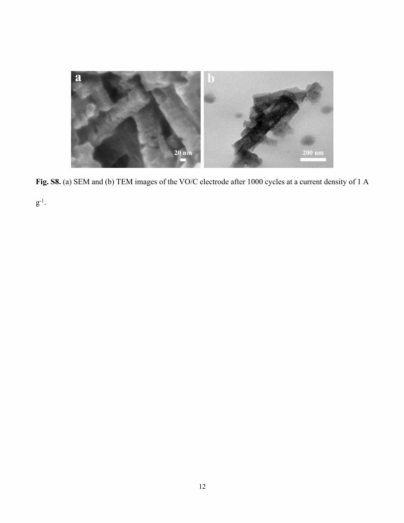
Fig. S8. (a) SEM and (b) TEM images of the VO/C electrode after 1000 cycles at a current density of 1 A
g-1.

13
Fig. S9. The electrochemical performance of the KPB cathode in half-cell. (a) The cycling stability of
KPB at 25 mA g-1 for 100 cycles in 2.0–4.1 V and (b) the corresponding charge/discharge curves.

14
Table S1. K-storage performance comparison of the VO/C electrode with previously reported metal
oxides-based anodes and some other representative anodes for PIBs.
Cycling performances Rate capability
Anode materials Current density(A g-1)
Cyclingnumber
Capacity(mA h g-1)
Current density(A g-1)
Capacity(mA h g-1)
Ref.
VO/C 0.11
4001000
345241
1/210/15
244/218133/104
This work
Co3O4–Fe2O3/C 0.05 50 220 Not given [7]
Pb3Nb4O13 nanowires 0.05 1100 74.6 Not given [8]
K1.06Mn8O16/CNT 0.1 500 226.5 1 127.2 [9]
V2O3@PNCNFs 0.05 500 ~230 1 134 [10]
HS-V2O3@C 0.1 500 330 5 79 [11]
SA-VO2 0.05 50 288.3 2 141.4 [12]
T-Nb2O5 0.4 400 ~76 1 74 [13]
MoO2/3DPC 0.050.5
200500
21395 Not given [14]
CuO nanoplates 0.21
60100
276.7206
12
206.8163 [15]
Sb2O3-RGO 0.10.5
1003300
309201 1 172 [16]
TiO2-carbon heterostructure
0.10.5
2001200
197.5132.8
12
114.697.3 [17]
MoO2/rGO 0.050.5
200500
218.9104.2 0.5 176.4 [18]
SnO2/SSM 0.051
100200
351128 1 125 [19]
Sb2MoO6/rGO 0.20.5
50100
381247 1 161 [20]
FeVO4/C 0.3 2000 252.9 12
200.6180.3 [21]
K0.23V2O5 0.1 100 97.6 0.4 92 [22]

15
VN quantum dots 0.10.5
100500
228215
12
187152 [23]
VS2 0.1 60 410 2 100 [24]
VSe2 0.2 200 335 2 169 [25]
MoSe2/N-C 0.1 300 258 12
195178 [26]
Graphite 0.14 50 100 0.28 80 [27]
Hard carbon 0.028 100 216 1.4 136 [28]
N-doped graphene 0.050.5
60500
320150 0.5 170 [29]
N-doped carbon nanofibers
0.0252
1004000
248146
1020
104101 [30]
S/N@C 0.1 400 200 24
91.264 [31]
S/O co-doped carbon
0.051
1002000
226.6108.4 1 158 [32]
N/O dual-doped hard carbon
0.051.05
1001100
230.6130 3 118 [33]
Bi 0.8 300 321.6 1.2 321.9 [34]
Bi/rGO 0.05 50 290 0.5 235 [35]
Sn4P3/C 0.05 50 307.2 1 221.9 [36]
FeP@C 0.1 300 205 12
6537 [37]

16
Table S2. The fitted impedances of VO/C and C.
Equivalent circuit model
Sample Rs () Rct ()
VO/C 2.982 596.9C 4.439 1751.0
In the equivalent circuit model, Rs represents solution resistance corresponding to the electrolyte and
electrical contacts, and Rct represents charge transfer resistance. As shown in Table S2, VO/C possess a
much lower Rct value than that of C, which demonstrates that the former has a better charge transfer
kinetic. This is also consistent with the superior rate performance and cycling stability of the VO/C
electrode.

17
References
[1] J. Reboul, K. Yoshida, S. Furukawa, S. Kitagawa, CrystEngComm 17 (2015) 323-330.
[2] G. He, L. F. Nazar, ACS Energy Lett. 2 (2017) 1122-1127.
[3] G. Kresse, J. Hafner, Phys. Rev. B 48 (1993) 13115-13118.
[4] G. Kresse, D. Joubert, Phys. Rev. B 59 (1999) 1758-1775.
[5] J. P. Perdew, K. Burke, M. Ernzerhof, Phys. Rev. Lett. 77 (1996) 3865-3868.
[6] G. Henkelman, B. P. Uberuaga, H. Jónsson, J. Chem. Phys. 113 (2000) 9901-9904.
[7] I. Sultana, M. M. Rahman, S. Mateti, V. G. Ahmadabadi, A. M. Glushenkov, Y. Chen, Nanoscale 9
(2017) 3646-3654.
[8] Z. Chen, X. Cheng, H. Yu, H. Zhu, R. Zheng, T. Liu, J. Zhang, M. Shui, J. Shu, Ceram. Int. 44 (2018)
17094-17101.
[9] S. Chong, Y. Wu, C. Liu, Y. Chen, S. Guo, Y. Liu, G. Cao, Nano Energy 54 (2018) 106-115.
[10] T. Jin, H. Li, Y. Li, L. Jiao, J. Chen, Nano Energy 50 (2018) 462-467.
[11] F. Chen, S. Wang, X.-D. He, J.-Y. Liao, Q. Hu, J.-M. Dong, C.-H. Chen, J. Mater. Chem. A 8
(2020) 13261-13266.
[12] Y. Li, Q. Zhang, Y. Yuan, H. Liu, C. Yang, Z. Lin, J. Lu, Adv. Energy Mater. 10 (2020) 2000717.
[13] N. Li, F. Zhang, Y. Tang, J. Mater. Chem. A 6 (2018) 17889-17895.
[14] S. Bao, S.-h. Luo, S.-x. Yan, Z.-y. Wang, Q. Wang, J. Feng, Y.-l. Wang, T.-f. Yi, Electrochim. Acta
307 (2019) 293-301.
[15] K. Cao, H. Liu, W. Li, Q. Han, Z. Zhang, K. Huang, Q. Jing, L. Jiao, Small 15 (2019) 1901775.
[16] J. Li, N. Zhuang, J. Xie, X. Li, W. Zhuo, H. Wang, J. B. Na, X. Li, Y. Yamauchi, W. Mai, Adv.

18
Energy Mater. 10 (2020) 1903455.
[17] Y. Li, C. Yang, F. Zheng, Q. Pan, Y. Liu, G. Wang, T. Liu, J. Hu, M. Liu, Nano Energy 59 (2019)
582-590.
[18] C. Liu, S. Luo, H. Huang, Y. Zhai, Z. Wang, ChemSusChem 12 (2019) 873-880.
[19] G. Suo, D. Li, L. Feng, X. Hou, Y. Yang, W. Wang, J. Electroanal. Chem. 833 (2019) 113-118.
[20] J. Wang, B. Wang, Z. Liu, L. Fan, Q. Zhang, H. Ding, L. Wang, H. Yang, X. Yu, B. Lu, Adv. Sci. 6
(2019) 1900904.
[21] X. Niu, Y. Zhang, L. Tan, Z. Yang, J. Yang, T. Liu, L. Zeng, Y. Zhu, L. Guo, Energy Storage
Mater. 22 (2019) 160-167.
[22] C. Liu, S. Luo, H. Huang, Z. Wang, Q. Wang, Y. Zhang, Y. Liu, Y. Zhai, Z. Wang, J. Power
Sources 389 (2018) 77-83.
[23] H. Y. Wu, Q. Y. Yu, C. Y. Lai, M. L. Qin, W. Wang, Z. W. Liu, C. Man, L. Y. Wang, B. R. Jia, X.
H. Qu, Energy Storage Mater. 18 (2019) 43-50.
[24] J. Zhou, L. Wang, M. Yang, J. Wu, F. Chen, W. Huang, N. Han, H. Ye, F. Zhao, Y. Li, Y. Li, Adv.
Mater. 29 (2017) 1702061.
[25] C. Yang, J. Feng, F. Lv, J. Zhou, C. Lin, K. Wang, Y. Zhang, Y. Yang, W. Wang, J. Li, S. Guo,
Adv. Mater. 30 (2018) 1800036.
[26] J. Ge, L. Fan, J. Wang, Q. Zhang, Z. Liu, E. Zhang, Q. Liu, X. Yu, B. Lu, Adv. Energy Mater. 8
(2018) 1801477.
[27] Z. Jian, W. Luo, X. Ji, J. Am. Chem. Soc. 137 (2015) 11566-11569.
[28] Z. Jian, Z. Xing, C. Bommier, Z. Li, X. Ji, Adv. Energy Mater. 6 (2016) 1501874.

19
[29] Z. Ju, P. Li, G. Ma, Z. Xing, Q. Zhuang, Y. Qian, Energy Storage Mater. 11 (2018) 38-46.
[30] Y. Xu, C. Zhang, M. Zhou, Q. Fu, C. Zhao, M. Wu, Y. Lei, Nat. Commun. 9 (2018) 1720.
[31] A. Mahmood, S. Li, Z. Ali, H. Tabassum, B. Zhu, Z. Liang, W. Meng, W. Aftab, W. Guo, H.
Zhang, M. Yousaf, S. Gao, R. Zou, Y. Zhao, Adv. Mater. 31 (2019) 1805430.
[32] M. Chen, W. Wang, X. Liang, S. Gong, J. Liu, Q. Wang, S. Guo, H. Yang, Adv. Energy Mater. 8
(2018) 1800171.
[33] J. Yang, Z. Ju, Y. Jiang, Z. Xing, B. Xi, J. Feng, S. Xiong, Adv. Mater. 30 (2018) 1700104.
[34] K. Lei, C. Wang, L. Liu, Y. Luo, C. Mu, F. Li, J. Chen, Angew. Chem. Int. Ed. 57 (2018) 4687-
4691.
[35] Q. Zhang, J. Mao, W. K. Pang, T. Zheng, V. Sencadas, Y. Chen, Y. Liu, Z. Guo, Adv. Energy
Mater. 8 (2018) 1703288.
[36] W. Zhang, J. Mao, S. Li, Z. Chen, Z. Guo, J. Am. Chem. Soc. 139 (2017) 3316-3319.
[37] F. Yang, H. Gao, J. Hao, S. Zhang, P. Li, Y. Liu, J. Chen, Z. Guo, Adv. Funct. Mater. 29 (2019)
1808291.