and electrochromic devices - georgia institute of...
TRANSCRIPT

Sohd State lomcs 60 ( 1993 ) 175-187 North-Holland
SOLID STATE IONICS
Polyorganodisulfide electrodes for solid-state batteries and electrochromic devices
S t e v e n J. Visco , M e l l i n L iu , M a r c a M. Doef f , Y a h P ing M a Ca r l L a m p e r t a n d L u t g a r t C. D e J o n g h e Untverstty of Cahfornta, Lawrence Berkeley Laboratory, Matertals Sctence Dtvtslon, 1 Cyclotron Road, Berkeley, CA 94720, USA
The use of polyorganodlsulfides m a variety of solid-state banenes and electrochromic devices is discussed Cychng data is presented for solid-state batteries using sodium and sodium-lead alloy negative electrodes with polyethylene oxide electrolyte and polydlmercaptothladlazole positive electrodes Rate capabilities are comparable to that for analogous hthmm batteries, but cells show continual deterioration with extended cychng The use of polyorganodisulfide electrodes as opucally passxve counter elec- trodes for electrochromlc dewces Is also described Solid-state devxces consisting of molybdenum doped WO3, amorphous poly- ethylene oxide electrolyte (aPEO), and a polyorgano&sulfide counter electrode colored rapidly from a pale yellow to a deep blue- green, upon apphcation of 1 2 V dc The photoplc transm]ttance changed from 61 to 9%, and the solar transmittance from 45 to 5% dunng the coloration process
1. Introduction
The t remendous d e m a n d for advanced bat tery systems for both the consumer and electric vehicle market has inspired fundamenta l and technical breakthroughs in non-aqueous and solid-state bat- tery technology. Still, ongoing ref inement o f conven- t ional secondary battery technology including nickel / c admium and sealed l e ad / ac id as well as innova- t ions such as the n i c k e l / m e t a l - h y d r i d e bat tery con- tmues to challenge the ant ic ipated advantages o f fu- ture technologies Advanced bat tery systems must demonst ra te strong improvements in terms o f vol- umetr ic and gravtmetr ic energy and power densi ty over n i cke l / cadmium and n i cke l /me ta l -hyd r ide systems and still offer comparable reliability in terms o f cycle life and safety. In this vein, a good deal of effort has been di rec ted towards l i th ium bat tery sys- tems [ 1 ] The use o f l i th ium metal negative elec- t rodes offers d is tmct advantages in terms o f specific energy and power However , unresolved issues re- garding the safety o f rechargeable h th tum bat ter ies using non-aqueous electrolytes have raised serious doubts concerning the viabi l i ty o f such systems Al- ternatives Include the use o f l i th ium-carbon anodes, LlxC6, or the use o f solid po lymer electrolytes (pos-
Elsevier Science Pubhshers B V
slbly bo th ) The use of LIxC 6 anodes in so-called LI- ion batteries, or rocklng-chatr batteries, has received much at tent ion m the last two years [2 -5 ] The sub- stitUtlOn of LIxC 6 for LI metal electrodes appears to greatly improve the cycleablhty of the negative elec- t rode and dramat ica l ly increases the safety of re- chargeable batteries based on LIxC 6 technology. Fur- thermore, the volumetr ic energy and power denstty o f Ll-lOn systems are almost as high as for LI metal anode batteries, although the gravlmetr lc energy denstty for the system is compromised to an extent that electric vehtcles may be an unrealist ic goal Al- ternatively, the high gravimetr lc and volumetr ic en- ergy densi ty o f L1 metal systems can be realized through the use o f solid po lymer electrolytes such as polyethylene oxide (PEO) Since their inception by Armand [6] , solid po lymer l i th ium bat ter ies have captured the interest of numerous researchers. Much of the early work on sohd polymer electrolytes was carried in the tempera ture range o f 60 to 100°C, where polyethylene oxide has suitable ionic conduc- tivity. Since then, a number o f groups have repor ted solid po lymer electrolytes with acceptable conduc- t ivi ty at ambien t tempera ture [7] , stgnlficantly broadening the scope of apphcat tons for solid poly- mer electrolytes
176 S J Vtsco et al I Polyorganodtsulfide elatrodes
The approach in this laboratory has included the use of solid polymer electrolytes in combination with polymeric organodisulfides and /o r polythlols These matermls are termed solid redox polymerization electrodes (SRPE's) to reflect the dynamic process of polymenzat~on/depolymenzat lon that occurs as these electrodes are oxidized and reduced Chemical synthesis of the polymers is easily accomplished by oxidation of d~- or trx-mercaptans by an appropriate oxidant as shown below,
n H S - R - S H + n H 2 0 2 ~ ( S R S ) , , + 2 n H ~ O , (1)
where R is an organic group such as ethyl, phenyl, etc The synthesis of a number of such polymers has been described earlier [8-10 ] The polymers are very inexpensive ( ~ $ 3 - 4 / l b ) , are non-toxic and bio- degradable Among the advantages of the polymeric organodlsulfides is the tremendous chemical flexi- bihty in altenng the physical, chemical, and electro- chemical properties of the polymers through syn- thetic means In addition to moderation of properties through the choice of the organic group R, copoly- mers are easily generated through oxidation of a mixture of mercaptans,
x H S - R - S H + y H S - R ' - S H + (x+y)H202
--, (SRS)x(SRS)r + 2 (x+y)H20, (2)
or through reaction of the polymers in the sohd state [ 11] The redox process for SRPE's can be repre- sented by,
( SRS ). + 2ne- --, 2n - S R S - , ( 3 )
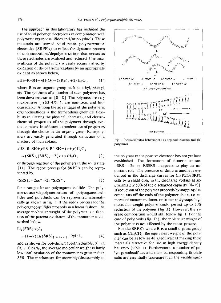
for a sxmple hnear polyorganodisulfide The poly- mer lzat ion/depolymenzat ion o f polyorganodlsul- tides and polythxols can be represented schemati- cally as shown m fig 1 I f the redox process for the polyorganodisulfides proceeds m a hnear fashion, the average molecular weight o f the polymer ~s a func- tion of the percent oxidation of the monomer as de- scribed below,
LIz(SRS) +yI2
= ( 1 --y)LI2(SRS)t i t (1-~)l + 2yLl l , (4)
and as shown for polyd~mercaptothmdlazole, X1 m fig 2 Clearly, the average molecular weight is fairly low until oxidation o f the monomer is greater than 85% The mechamsm for assembly/disassembly of
i
LI + "S l : qS " LI+ LI + "SF : IS " LI + LI + "SRS" LI + Li + "SR$" LI +
LI + "S l qS " kl + Li + "SRS" LI + LI + "SF IS " El +
(O) po l yo rganod l su l f l deS
R-R R-R-R-R-R-,R-,R-,R-7-1-1 I I i ~ S S I I I I I i / / A A _ m s s - S ~ +
S S S ' -S S b o ~ L l+ L I +
s s s - s s s s s s s s s I I I I I I I I I " S - s s
( b ) po l y t h l o l s
Fig 1 Idealized redox behavior of (a) organodlthiolates and (b) polythlols
the polymer in the posmve electrode has not yet been estabhshed The formation of d lmenc anions, - S R S - - 2 e - c ~ - R S S R S - , appears to play an im- portant role The presence of dlmerxc amons IS evi- denced m the discharge curves for Lx /PEO/SRPE cells by a shght drop m the discharge voltage at ap- proximately 50% of the discharged capacity [ 8-10 ] If reduction of the polymer proceeds by snipping dis- crete units off the ends of the polymer chain, i e re- moval of monomer, dlmer, or tnmer end groups, high molecular weight polymer could persist up to 50% reduction of the polymer (fig 3) However, the av- erage composition would still follow fig 1 For the case of polythxols (fig lb) , the molecular weight of the polymer is not affected by the redox process
For the SRPE's where R is a small organic group such as CHECH2, the eqmvalent weight of the poly- mer can be as low as 46 g/eqmvalent making these materials attractxve for use in htgh energy density batteries (table 1) Furthermore, a number of po- lyorganodlsulfides and their corresponding thxolate salts are essentmlly transparent in the V~slble spec-

S J Vtsco et al / Polyorganodtsulfide electrodes 177
2O
-~ 18 L,= = 16 r~ ,~ t,.
"~12 I
• ~ 10 N.N
95% Oxldatmn
I anion dlmer ==
O / I I I I I I I I I
0 10 20 30 40 50 60 70 80 90
% Oxidation of SRS Monomer (lithium salt)
I
100
Fig 2 Average molecular weight for linear polymenzatlon Ofdlthlolate amons as a function of% oxidation ofamons
~ 09
O8
o7
o~
04
"~ 03
_g o2
o
\ ' ' l i ~ ( S R S ) ~ + 2yD = LI2(SRS)~v + ylJ2(SRS)
\ \ \
\ :Sn"
"L, I I 40 60 80 100
% Reduction of Linear ORGANODISULFIDE Polymer
Fig 3 Relative change m molecular weight of polymer chains if redox sclssion of&sulfide bonds removes discrete units from the ends of the polymer chains
trum Accordingly, polyorganodlsulfides can func- tion as transparent, optically passive, counter elec- trodes in electrochromlc devices.
I 1 Use o f SRPE's In batteries
A number of sohd redox polymerization elec- trodes have been prepared and described in terms of solid-state hthlum battery performance [ 8-11 ]. The majority of these batteries have used polyethylene oxide as the sohd polymer electrolyte, although, for ambient temperature testing, oxymethylene-llnked
polyethylene oxide [ 7 ] (amorphous PEO) was found to exhibit acceptable lomc conductivity as well as good mechanical properties Since polyorganodlsul- tides are not electronically conductive, carbon black is also dispersed in the positive electrode In prin- ciple, SRPE's can function as positive electrodes for a number of metal negative electrodes. In fact, early tests on SRPE's were done using liquid sodium elec- trodes and 13"-alumina electrolytes [ 9 ] Sodium neg- ative electrodes offer advantages over hthlum in- cluding greater abundance, ease of processing, and much lower cost. The theoretical energy densities shown in table 2 for the sodlum/SRPE cells are somewhat lower than for the hthlum ceils, but are stdl in excess of the requirement for electric vehicle and/or consumer electronic devices Other possibll- rues include sohd-state rocking chair technologies using SRPE positive electrodes and appropriate in- sertion of intercalation electrodes L1/SRPE cells us- ing hquid electrolytes have demonstrated high dis- charge rates [ 12 ], however, thlolate anions generated on cell discharge may have appreciable solubility in non-aqueous solvents leading to lower cycle life It IS possible, in prmople, to construct a rocking-chair battery entirely from SRPE's, and thus have an all polymer battery, although the 1 V OCV (table 1 ) hardly leads to inspiring energy densities. Polyor- ganodlsulfides could be used in combination with LlxC6 anodes (table 3) with acceptable volumetric energy densities, however, the gravlmetrlc energy densities may not be acceptable for electric vehicle

178 S J Vtsco et al / Polyorganodtsulfide electrodes
Table 1 Nomenclature for polyorgano&sulfide electrodes, and energy densities of hthlum solid polymer batteries based on them
ID SRPE Description E W mAh/g mAh/cc V.om Wh/kg Wh/~ eqmv/g vs Ll
L1 lithium 7 3,829 2,045 X0 (SCH2CH2OCHzCH2S)n clear, viscous 76 353 564 2 646 885
liquid N - - N ) II II
XI C C 74 362 652 2 8 990 1384 / \ / \
S S S I S I
C / XX
X5 N N II I C C
/ \ // \ S N SJ
X8 (SCH2CHzS)n white powder 46 583 932 2 1,012 1,28t
Table 2 Theoretical energy densities of sodium solid polymer batteries having polyorganodlsulfide cathodes
ID E W mAh/g mAh/cc Vno m Wh/kg Wh/£ eqmv/g vs Na
pale, yellow powder
pale, yellow powder 58 462 739 3 1,237 1,629
sodium 23 1,165 1,142 X0 76 353 564 1 7 460 642 X1 74 362 652 2 7 746 1,121 X5 58 462 739 2 7 894 1,212 X8 46 583 932 1 7 660 873
Table 3 Theoretical energy densities of representative battery systems
Electrode E W Capacity Vno m Vno m Lithium LIC)2 Lithium LIC,2 eqmv/g mAh/cc vs L1 vs Cx (Wh/kg) (Wh/kg) (Wh/£) (Wh/£)
LI (4 1) 28 511 LIC12 196 a) 246 a) L1N102 195 686 3 6 3 2 494 205 1900 558 LIMn2Oa 181 740 3 9 3 5 578 216 2182 551 SRPE (X1) 74 652 2 8 2 1 930 208 1384 375
a) Equivalent weight and volumetric capacity of composite having 60 vol% active carbon
a p p h c a t l o n s (fig. 4 ) F u r t h e r m o r e , i t is u n c l e a r
w h e t h e r LlxC6 e l ec t rodes will f u n c t i o n p r o p e r l y w i t h
so l id p o l y m e r e lec t ro ly tes as i t a p p e a r s t h a t e i t h e r
p r o p y l e n e or e t h y l e n e c a r b o n a t e IS neces sa ry for pas-
s w a t t o n o f the c a r b o n e l ec t rode sur face for e x t e n d e d
c y c h n g [ 2 - 5 ] A s s u m i n g t h a t so l id p o l y m e r tech-
no logies a v o i d t he safe ty p r o b l e m s a s soc i a t ed w i th
c y e h n g alkal i m e t a l e l ec t rodes in n o n - a q u e o u s elec-
t rolytes, the m o s t des i rab le con f igu ra t ions for S R P E ' s
a p p e a r to be m s o h d p o l y m e r cells u s ing e i t h e r l i th-

S J Vtsco et al I Polyorganodtsulfide electrodes 179
"e
1000 900 800 700 600 500 400- 300- 200 100
0 Lithmm 4 1 Composite LICI2 Composite LICl0
8 .o
800
700
600
500
400-
300-
200 ~
100
/ / ~ - ~ [ ] L)(41)
LI2NIO2 LI2Mn204 SRPE
Fig 4 Calculated gravlmetrlc capaoty and energy density for LI (4 1 excess) and composite LlxC6 electrodes (60 vol% achve material ) (a) gravlmetric capacity, (b) gravlmetrlc energy density for representative battery systems
turn or sodium metal or alloy electrodes The per- formance of L1/PEO/SRPE cells has been reported m detail elsewhere [8-12] The behawor of N a / PEO/SRPE ceils will be discussed here.
1 2 Use ofSRPE's m electrochromw devices
Electrochromic devices can be used for the regu- lation of incident solar energy and glare in buddmgs, vehicles and aircraft. The worldwide production of flat glass is about 1 bill ion m 2 per year, so the po- tential for switching applications is very large. A schematic representation of a sohd-state electro- chromic device is shown in fig 5 In a typical device, metal oxide insertion (or intercalat ion) electrcdes are chosen such that complementary coloration of the electrodes occurs upon application of a sufficient voltage bias across the cell, one of the electrodes colors upon oxidation while the other electrode colors
upon reduction, similarly upon application of a suf- ficient reverse bias, complementary bleaching of the two electrodes occurs. However, upon prolonged cy- cling, parasitic reactions may reduce the capacity of
Fig 5 Schematlcrepresentatlonofsohd-stateelectrochrommde- vice consisting of transparent ldlum-doped tm oxide (ITO) cur- rent collectors, sohd polymer electrolyte, and complementary metal oxide electrochromlc layers

180 S J Vtsco et al / Polyorganodzsulfide electrodes
one electrode, even i f the electrodes were matched inltmlly The dewce then becomes unbalanced and is unable to bleach fully One way to avoid this prob- lem ts to use an opncal ly passive ion storage elec- t rode that undergoes redox without an assocmted color change Since the major i ty of the known elec- t rochromlc electrodes reversibly insert (or interca- late) canons, a s tatable redox electrode would pos- sess electroactive anions such as the organothmlates The pert inent half-reaction for coloring and bleach- lng WO~ can be represented as,
WO3 (bleached) + n e - + nLi +
.~-LI.WO3 (colored) (5)
and for the SRPE,
nLl2 (SRS)
<. ( S R S ) . + 2nLl + + 2ne - ( p a s s i v e ) , (6)
givmg a cell reactmn for the electrochromic device a s
WO3 (bleached) + nL12 ( S RS )
-~ ( S R S ) . + LIE. WO3 (colored) (7)
In the case of an opncal ly passive SRPE, the capacity need not be matched to the electrochrom~c elec- trode, but rather would be formulated with excess capactty A diagram of such a devtce is shown in fig 6 Since the polyorganodlsulf ides are not electroni- cally conducttve, the redox reaction must take place m the v~cmity of the t ransparent current collector Fortunately, the amount of charge needed to revers- ibly color and bleach many electrochromic elec- trodes is qmte small, in the range of 25 to 40 m C / cm 2, and can be achieved with polyorganodlsulf ides in the absence of conducnve addtnves
Plate G l a s s / Plastic
I ±_
e"
W O 3
I LixWO3
Li +
X
* - - ~ Li ~¢]
il-' Plate G l a s s /
Plas~e
~ p ~ D E SnO~ WO,
ass sltdes
Fig 6 Sohd-state electrochromlc device based on sohd redox polymenzatxon electrodes Coloring/bleaching reaction occurs only at metal oxide electrode, SRPE is optically passive and functions only as redox active ion storage electrode

S J Vtsco et al / Polyorganodtsulfide electrodes 181
2. Experimental
2 1 N a / P E O / S R P E cells
Alkali metal purification and cell assembly/test- ing was carried out in an inert atmosphere glove box with less than 1 ppm 02 and H20. Reagent grade so- dium was treated wxth sodium oxide at 350°C to re- move calcium, then filtered with stainless wool to fil- ter out the oxides Roughly purified sodium was then reacted with titanium sponge at 400°C to remove oxygen Sodium-lead alloy, Na375Pb, was directly made by melting the appropriate amount of purified sodium and lead in an ct-alumlna crucible Polyeth- ylene oxide (PEO) of molecular weight 1 × 10⁶ and NaSO3CF3 (Na ethylene oxide ra t lo=l 8) were dissolved in acetomtrde and cast on release sheets in suitable volumes to give 10 to 40 micron films after solvent evaporation. Electrolyte films were dried un- der vacuum for four days pnor to testing in sohd-state cells Composite positive electrodes with surface ca- pacities of 2 to 6 C/cm 2 were cast from solutions of PEO, NaSO3CF3 (Na /EO= 1 20), and carbon black and dried as above Positive electrodes having no carbon black were used for cyclic voltammetry ex- periments. Assembled cells were cycled galvanostat- lcally under software control.
2 2 WOs /aPEO/SRPE electrochromtcs
Molybdenum doped tungsten oxide films were de- posited potentlostatlcally from a bath consisting of tungsten and molybdenum metal dissolved in aqueous hydrogen peroxide onto conductive ra- dium-tin oxide (ITO) coated glass electrodes (Don- nelly Co, Holland, MI), using a BAS potentlostat/ coulometer (model CV-27). The ITO electrodes were ultrasonically cleaned, dipped in ethyl alcohol, dipped an 10-20% sulfuric aod, nnsed in dlstdled water and dried with mtrogen prior to the deposition After de- position, the electrodes, approximately 3 × 5 cm in size, were nnsed in d~stllled water and dried with ni- trogen Ion conducting layers were cast onto the col- oring electrodes from solutions of high molecular weight amorphous PEO and hthlum tnflate (LI ethylene oxide ratio= 1 20) in acetomtnle (2- 4 wt% solids) and allowed to dry completely. These films were estimated to be less than 10 ~tm thick Ion
storage counter electrodes were cast directly onto the dried ion conductor layers from solutions of amor- phous PEO (aPEO), lithium trlflate and the lithium dlthlolate salt of the polyorganodisulfide being tested Upon drying of the SRPE films, the polymer elec- trodes were either colorless or pale yellow, depend- ing on the choice of thlolate salt Electrochromlc cells were assembled as shown In fig 6 After drying, an- other ITO coated glass electrode was placed on top of the ion storage layer, such that the active area of the device was 3 × 3 or 9 cm 2 The edges were sealed with a hot melt adhesive, and care was taken to pre- vent contact of the glue with the internal compo- nents during the curing Devices were colored and bleached by application of a controlled potential from a custom dc power supply with current regulation A Cary 14 UV-vlslble spectrophotometer was used to take optical transmittance spectra WO3 used as the electrochromlc material for this study intercalates cations upon reduction (application of potential to the device) and demtercalates cations upon oxida- tion (reversal of the potential) Molybdenum is added to the WO3 to alter the color from bright blue to gray-blue, but does not participate in the redox process. In SltU spectrophotometry on the WO3 Mo electrode was performed using a special quartz cell with a micro-calomel reference electrode, a platinum foil counter electrode was used while a potential of - 0 7 V versus S C E. was applied to the electro- chromic electrode in order to color it
3. Results and discussion
3 1 N a / P E O / S R P E and Nas 75/PEO/SRPE cells
The solid-state cyclic voltammogram for polydl- mercaptothladiazole (X1) is shown in fig 7 The CV exhibits the chemically reversible and klnetlcally quasi-reversible behavior characteristic to organo- disulfides [ 13,14 ] and polyorganodlsulfides In fact, polydlmercaptothiadlazole exhibits the fastest elec- trode kinetics of any of the organodlsulfides or po- lyorganodlsulfides examined so far The relatively slow electrode kinetics of the disulfides are compen- sated by the use of high surface area carbons in the formulation of positive electrodes
Shown In fig 8 are the discharge curves of a Na/

182 S J Vlsco et al / Polyorganodtsulf ide electrodes
15
30 w t % Xl in aPEO
Scan Rate was = 200 0000 Scan Rate was = 100 0000 Scan Rate was = 50 0000 mV/sec total number ot mV/sec total ntunber ot mV/sec total number ot
tyler= 2 cyles= 2 cyles= 2
0
05 -[
o
2 I
22 ~ " " ~ ( , , ~ 2 6 / 3 32 34 36 38 4
-0 5
TEMP = 88 C
/ /
Fig 7 Solid-state cychc voltammogram of polydlmercaptothladmzole m amorphous PEO electrolyte at 90°C 30 micron hthmm refer- ence and counter electrodes were used m the sohd-state cell
PEO/X1 cell operated in the temperature range of 70 to 85°C The cell shown m fig. 8 was mlUally cycled at shallow depth ( 10 to 20% of available ca- pacity for 60 cycles) to improve the N a / P E O inter- facial contact Preliminary impedance spectroscopy studies of N a / P E O / N a cells in this laboratory have shown that the quality of the interface depends crit- ically upon ~mpuntles m the sodmm electrode, and in the PEO electrolytes (moisture and /o r residual solvent); L1/PEO cells were not found to be as sen- SltlVe to contaminants This cell achieved over 90 cycles, with 30 cycles between 40 to 60% of avadable capacity, although gradual detenoratmn of cell per-
formance was observed with cyclmg Clearly, the rate capablhty of N a / P E O / X 1 cells at this temperature is not as good as that of L1/PEO/X1 cells [8-11 ] Na/ lY' -a lumma/SRPE cells operated at 130°C have demonstrated very high rate capabdlty [9] . How- ever, the melting point of sodium, 97 ° C, sets the up- per hm~t of the operating temperature of all-solid- state N a / P E O / S R P E cells
Sodium-lead alloy has been reported to perform well as a negative electrode for sodium batteries [ 15 ], and is not limited by a low melting point The cy- cling behavior of a Na37sPb /PEO/X 1 cell operating at 90 ° C is shown m fig. 9. The rate behavior of the

S J Vtsco et al / Polyorganodlsulfide electrodes 183
35
i 25
2
0
1
05
t 27% 42 5% #67-#71 #76-#81
Na/PEO/X|
Theoretical Capac~ 2.8 C/cm"
Jc= 010 mA/cm =
Jo= 0 25 mA/cm 2
70-85*(3 I [ I [ I I I I I I
20 40 60 80 100 120
Uhhzat)on of Cathode (%)
Fig 8 Charge/discharge curves for Na /PEO/X1 cells operating at 70 to 85°C F]rst 60 cycles involved shallow discharges ( 10 to 20% of avadable capacity) to condmon cell
cells is clearly improved by the higher operat ing tem- perature. The first 15 cycles of this cell look prom- lslng, however, subsequent cychng shows consistent deterioraUon. Four probe dc measurements using current-pulse techniques have correlated this dete- r iorat ion to increasing resistance at the N a / P E O or Na3 75Pb/PEO interface. The degradation of the N a / PEO interface may be due to ei ther water or solvent present in the PEO electrolytes, or possibly due to migrat ion of thlolate anions towards the sodium negative electrode, and subsequent react ion Lith- ium electrodes are less prone to interracial degra- dat ion due to their super ior abi l i ty to form passi- vat ion films
3 2 W O / a P E O / S R P E cells
Amorphous PEO (aPEO) electrolytes were found to have good d imensional s tablhty and excellent op- tical proper t ies The optical t ransmi t tance of an aPEO electrolyte IS shown in fig. 10 The electrolyte films appear complete ly t ransparent to the human eye. The spectral proper t ies o f an S R P E / a P E O film
are shown in fig 1 1, the electrode is faintly yellow to the human eye Tungsten oxide, WO3, intercalates cations upon reduction (appl icat ion of potential to the device) and delntercalates cations upon oxlda- non (reversal o f the potent ia l ) as described in eq (5) The visible t ransmit tance spectra for WO3 Mo in both the bleached and the colored state are shown in fig 12 The photoplc t ransmit tance (Tp) changes from 0 83 to 0 19 when a voltage of - 0 7 versus S C E. is appl ied to the electrochromic electrode in
a 0 1 M H2SO4 solution The current -vol tage characterist ic of an I T O /
W O 3 / a P E O / S R P E / I T O device is shown in fig 13 When a voltage of about 1 3 V is appl ied between the WO3 Mo and counter electrode for this example, current flows and the device rapidly colors to a deep blue-green, indicat ing that Li ions are intercalating into WO3 as it is being reduced Concurrently, the dl thlolate salts in the ion storage layer are oxidized to disulfide polymers and release Ll Ions When a po- tential of about - 1.0 V is apphed to the colored de- vice, rapid and complete bleaching to the original pale yellow occurs, the electrochromic electrode is reox-

184 S J Vtsco et al / Polyorganodlsulfide electrodes
~ (a) Jo= 0 35 mA/cm 2
25
2
> #6-#15
• #1 -#5
°i1 0 20 40 ~10 80 100
Cathode Utilization (%)
4
i 2.5
2
O5
(b) Jo = 0.40 m N c m 2
0 20 40 80 80 1(30
Cathode Ut i l izat ion (%)
Fig 9 Cychng ofa Na~ 75Pb/PEO/X 1 cell at 90°C
ldlzed and demtercalates LI, and the counter elec- t rode Is depo lymenzed to the h t h m m d~thxolate salt Switching t imes for both the coloring and the bleach- mg processes are less than one minute
The optical spectra of the dewce m both the col- ored and the bleached states are presented m fig 14 The photoplc t ransmit tance, Tp, changed from 61 to 9% and the solar t ransmit tance, T~, from 45 to 5%, upon colonng The optical propert ies and swxtchmg t imes vary somewhat depending upon the com- pounds used m the 1on storage layer, but the results
presented above are fairly typical The devices re- main stable in both the colored and bleached states, and cycle well, laboratory cells have demonst ra ted several hundred switching cycles thus far
4. Conclusions
Polyorganodlsulf ide electrodes have unique ad- vantages as posit ive electrodes m solid-state alkah metal bat teries and as opUcally passxve counter elec-

S J Vtsco et al / Polyorganodtsulfide electrodes 185
1 0 0 -
8 0 -
-
. ~ 6 0 -
~ -
~,~-
2 0 -
200
F S u b s t r a t e
I I I I I I I I 3 0 0 4 0 0 5 0 0 6 0 0 7 0 0 800 900 1 0 0 0 1 1 0 0
Wavelength (nm)
Fig 10 Optical transmRtance of an aPEO electrolyte layer The solid line shows the spectrum of the substrate and dotted line that of the
aPEO layer
I=
I00 1(1(I
90
70
6 0
50
4 0 _
20 --
I0
0
3O0
I I I I
I 1 I
400 .~00 600 700
W A V FJ J,,~NG'I'I | (nm)
800
Fig 11 Spectral optical transmittance of h thmm 2 5-dnmer- capto-1,3,4 thnadmzole salt m aPEO Film thickness is approxi- mately 10 microns The electrode ns faintly yellow to the human eye
a I [ ]
(z;
90
70
60
s0
2O
7
o I I I I
4O0 5OO 6OO 700 80~
WAVEJ.E~G1]! (nm)
Fig 12 Normal transmittance for an electrochromlc WO3 Mo/
ITO/glass electrode m a hqmd cell (0 1 M H2SO4) m the bleached and colored states Coloration occurs at a voltage of - 0 7 V ver- sus an SCE

186 S J Vtsco et al I Polyorganodlsulfide electrodes
0 07S
0 0S0
0 0 2 5
E U 0
t - - 0 025
Z -0 0S0 e~
(.)
- 0 0 7 5
-1 0 0 0 '
I I I
-1 0 2 5 I I I
- 2 . 0 - 1 O 0 l 0 2
P O T E N T I A L (V)
Fig 13 Current-voltage charactensUcs of an electrochromlc de- wce with a WO3 Mo electrode, aPEO sohd electrolyte, and ion storage later contammg the hthmm dtthlolate salt of 2 5-dtmer- capto- 1,3,4 thladtazole
z <
z <
lOO
90 --
80 - -
70 - -
60 --
50 --
40 --
30
lO
o 30o
I I I I
I 400 500 600 700 800
WAVELENGTH (am)
Fig 14 OpUcal transmittance ofelectrochromlc device havmg a WO3 Mo electrode, aPEO sohd electrolyte, and ton storage later containing the hthmm dtthlolate salt of 2 5-dtmercapto-l,3,4 thmdmzole
trodes for electrochromtc devices The polymers are easily synthesized, have great chemical flexlbthty, are inexpensive, and possess very low equivalent weights
The use of polyorganodlsulfides in sohd-state so- dium batteries is promising, but rate capability ap- pears to be hmtted by the upper temperature hmit of the sodium neganve electrode, and cells show ca- pacity loss on cycling Na375Pb/PEO/SRPE cells operatmg at higher temperatures achieve rate capa- bthttes comparable to analogous L1 cells, but also show deterioration on extended cychng. The use of sodmm electrodes m sohd polymer batteries ts at- tractive due to the much lower cost of sodium metal relative to h thmm metal Rehabthty of the N a / P E O mterface needs to be addressed m further detail
Polyorganodlsulfide electrodes function well as ton- storage electrodes m solid polymer electrochromlc devices Amorphous PEO appears to be a good elec- trolyte for this solid-state device, exhibiting ade-
quate tonic conductivity at room temperature and
good mechanical stablhty The use of aPEO electro- lytes and SRPE ion-storage electrodes allows con- structlon of a stable, completely sohd state wmdow with excellent optical properties and switching rimes Because the new ton storage layer does not change color as a functton of redox state, there is no need to match the capacity to that of the WO3 electrodes This greatly simplifies the assembly process, and thus rep- resents a potential saving m manufactur ing cost
Acknowledgement
This work was supported by the Assistant Secre- tary for Conservation and Renewable Energy, Office of Transportat ion Technologies, Electric and Hybrid Propulsion Division of the U S Department of En- ergy under Contract No DE-AC03-76SF00098

S J Vtsco et al / Polyorganodtsulfide electrodes 187
References
[ l ] J P Gabano, Llthmm Batteries, (Academic Press, London, New York, 1983 )
[2] R Fong, U V Sacken and J R Dahn, J Electrochem Soc 137 (1990) 2009
[3] J Dahn, U V Sacken, M W Juzkow and H Al-Janaby, J Electrochem Soc 138 (1991) 2207
[4] J M Tarascon and D Guyomard, J Eiectrochem Soc 138 ( 1991 ) 2864
[5]D GuyomardandJ M Tarascon, J Electrochem Soc 139 (1992) 937
[ 6 ] M B Armand, J M Chabagno and M J Duclot, m Fast Ion Transport in Solids, eds P Vashlshta, J N Mundy and G K Shenoy (North-Holland, Amsterdam, 1979) p 131
[7] C Booth, C V Nicholas and D J Wilson, in Polymer Electrolyte Revmws, eds J R MacCallum and C A Vincent (Elsevmr, New York, 1989) p 229
[ 8 ] S J Vlsco, M Lm, M B Armand and L C De Jonghe, Mol Cryst Llq Cryst 190 (1990) 185
[9] M Lm, S J Vlsco and L C De Jonghe, J Electrochem Soc 138 (1991) 1896
[ 10] M Lm, S J Vlsco and L C De Jonghe, J Electrochem Soc 138 (1991) 1891
[ l l | M M Doeff, M Lerner, SJ Vlsco, M Ueand LC De Jonghe, J Electrochem Soc 139 (1992) 2077
[12]MM Doeff, SJ Vlsco and LC De Jonghe, J Appl Electrochem 22 (1992) 307
[ 13 ] M Lm, S J Vlsco and L C De Jonghe, J Electrochem Soc 136 (1989) 2570
[14] M Lm, S J Vlsco and L C De Jonghe, J Electrochem Soc 137 (1990) 750
[ ! 5 ] T R Jow and L W Shacklette, J Electrochem Soc 136 (1989) I