and - efotg.sc.egov.usda.gov · install lightening arrestors and chokes to ... ppt lumber shall be...
TRANSCRIPT

PA382 - 1
Technical Guide Section IV Pennsylvania May 2006
CONSERVATION PRACTICE STANDARD
FENCE
(Feet)
CODE 382
DEFINITION
A constructed barrier to animals, or people.
PURPOSES
This practice may be applied as part of a con-servation management system to facilitate the application of conservation practices that treat the soil, water, air, plant, animal, and human resource concerns in order to:
• Implement a prescribed grazing plan and provide better distribution of grazing live-stock.
• Protect grazing animals from hazardous areas such as sinkholes, poisonous plants, and roads.
• Protect protection of streams, wetlands, and other water bodies to increase or pro-tect water quality.
• Provide protection of new seedings or plantings.
• Regulate access to areas by people or animals.
CONDITIONS WHERE PRACTICE APPLIES
This practice applies on any area requiring control or exclusion of livestock, wildlife, preda-tors, or people.
CRITERIA
General criteria for all purposes
Fencing material, type, and design shall be of a quality and durability that meets the intended management objectives.
Use 12 ½ gauge wire for the exterior fence and a smaller gauge wire can be used for the inte-rior.
Locate fences to facilitate maintenance. When possible, avoid irregular terrain, water cross-ings, and narrow corners. Where applicable, clear right of ways should be established and maintained to facilitate fence construction and maintenance. The purpose of the fence shall be factored into determining the type of fence to be con-structed. Sheep and hogs may require woven wire, horses may require wooded or other non-injurious types of fence, cattle may be con-tained with electrified wire, and chain link fence may be required to control people access to areas.
All fences shall consist of acceptable designs to meet the intended purpose and lifespan of the practice.
Height, number and spacing of wires will be installed to facilitate control and management of animal(s) or people of concern.
Height, size, spacing, and type of posts will be used that best provides the needs for the style of fence required.
Selection and design of fences shall adhere to manufacturer's recommendations to ensure suitability to use and site conditions.
All fence design shall comply with federal, state, and local regulations, easements, and access agreements.

PA382-2
Technical Guide Section IV Pennsylvania May 2006
The landowner shall obtain all necessary per-mits prior to construction and installation.
Additional criteria to implement prescribed grazing management Improve resource management by locating fences to separate areas with differences in forage seasons of growth and palatability, use, topography, or production potential.
Pasture/paddock divisions shall be consistent with grazing needs as projected by a grazing plan developed under Pennsylvania Conserva-tion Practice Standard Prescribed Grazing, (Code 528A).
Locate fences to control livestock access to water and handling facilities. Any permanent fencing for grazing livestock should allow flexibility to facilitate implementa-tion of the prescribed grazing plan and permit land management activities such as nutrient application, pest control, forage harvest, and other appropriate practices.
Locate fences to facilitate livestock manage-ment, handling, watering, and feeding.
CONSIDERATIONS
Place warning signs on electric fences a mini-mum of 300 feet apart.
When possible, install fences across slopes to improve grazing distribution, rainfall infiltration, and reduce soil erosion.
Consider the movement needs of wildlife when locating fences. Fence wire height may re-quire adjustments to repel predators or avoid entanglement.
When using electrified fences to control live-stock, a training area should be used to condi-tion livestock to fences.
PLANS AND SPECIFICATIONS
Plans and specifications are to be prepared for specific sites based on this standard.
Plans and specifications for installing fences shall be in keeping with this standard and shall describe the requirements for applying the practice to achieve all of its intended purposes.
Safety – is a concern when constructing elec-tric fences. The following are guidelines of safety to adhere to:
1. Do not allow guide or line wires to contact any power lines.
2. Do not erect wires or ground wires near overhead power lines, telephone wires, or radio antennas. It is illegal to cause inter-ference.
3. Install energizers inside a building when possible. Energizers need not be attached to a power pole. All power supply lines should comply with local electrical codes.
4. All energizers must be connected to a separate grounding system. Never attach energizer to other farm related grounding devices (i.e. electric panels ground rods, lightning rods on buildings, houses, barns, etc.). Fence charger ground rods need to be at least 6 feet away from grounding rods that are not part of the fencing sys-tem.
5. Only one energizer should be installed onto a fence line.
6. Where there is public access to the fence, both interior and exterior fence, warning signs should be placed at a minimum of 300 feet apart.
7. Warn all children that electric fencing is being used and let neighbors know where and how to shut off the current.
8. Install lightening arrestors and chokes to protect fence.
OPERATION AND MAINTENANCE
The designer shall provide an Operation and Maintenance plan to guide the landowner in assuring the intended service life of the fence. The O&M plan shall include, but not be limited to the following items, as applicable to the type of fence being used. Additional guidance shall be included, specific to the type of fence and its use.

PA382-3
Technical Guide Section IV Pennsylvania May 2006
Regular inspection of fences shall be part of an ongoing management program. Inspection of fences after storm events is needed to facili-tate the function of the intended use of the fence.
Retain and properly discard all broken fencing material and hardware. All necessary precau-tions should be taken to ensure the safety of construction and maintenance crews.
Check all fence systems for proper functional-ity and maintain tension to design specifica-tions. Where electric fences are used, periodi-cally check output of charger with a voltmeter.
Annual clearing of weeds and brush under and near the fence systems will prolong life expec-tancy. Maintenance and repairs shall be per-formed in a timely manner to maintain the de-sired control. For streams or water crossings where the depth of the stream is less than 1/3 the height of the fence, the fence will run uninterrupted. For streams of greater depth end the main fence at the top of the streambank on each side with an appropriate end assembly. From separate posts driven next to the end posts, construct a separate section of fence across the watercourse that shall be de-energized during high flow or flooding conditions. The only tie between the main fence and the sec-tion spanning the watercourse shall be a single electrical connection.
FENCE CONSTRUCTION SPECIFICATIONS 1. Scope
The work shall consist of furnishing materials and installing all components of the fence as outlined in this specification and the drawings.
Construction shall be performed in a manner that meets the intended management objec-tives.
Safety is a primary concern. Wire that is over-stretched may break and recoil. Eye and hand protection should be worn. Follow all manu-facturers’ safety precautions for handling and installing fencing materials.
Wire should be attached on the side of posts that will receive the greatest pressure from animals. Wires will be placed on the outside of posts on curves.
Locate fences to facilitate maintenance. When possible, avoid irregular terrain, water cross-ings, and narrow corners. Where applicable, clear right of ways should be established and maintained to facilitate fence construction and maintenance.
2. Materials
Fence
Barbed Wire – will consist of not less than 4 wires and shall be a minimum of 12 ½ gauge with a 4-point barb spaced no more than 6 inches apart.
Woven Wire – will consist of a high tensile woven wire with a minimum of gauge 12 ½. Vertical wire spacing shall not be more than 12 inch. Height depends on the class of livestock to be controlled.
Wooden Boards – The boards should be 1 inch thick and at least 6 inches in width (1 X 6) with lengths of 16 feet wherever possible.
Polywire/ Polytape –Polywire and polytape shall have a minimum of 6 stainless steel, copper, or aluminum strands running through the fabric.
Chain Link – shall be a minimum of 4 foot high, 9 gauge wire woven into a 2 inch diamond shape in which the individual pickets are heli-cally wound and interwoven to form a continu-ous link fabric. Hot-dipped galvanized material will be 2 ounces of zinc coating per square foot and should be evenly distributed over the en-tire fabric as per ASTM A392, Class II. The following minimum breaking strength shall ap-ply: 1290 pounds and be 9 gauge (0.148"). The fabric shall be twisted, top and bottom. All chain link fence fabric will carry the manufac-turer's identification tag. High Tensile Wire*- shall be new, smooth, and meet or exceed the following specifications:
1. 1000 lbs. breaking strength.
2. type III galvanized.
3. 16 gauge wire minimum.

PA382-4
Technical Guide Section IV Pennsylvania May 2006
4. 250 lbs. minimum tension per wire with in-line strainer.
Fasteners*.
Nails* – for board fence, nails should be gal-vanized and not less than 3 1/2 inches long
Insulators – The type and size of insulators shall meet the requirements to fasten electric fence materials to a post.
Staples* - Stapes should be of 9 gauge galva-nized wire with a minimum of 1 ¼” length. Clips* - The type and size of clips shall meet the manufacturer’s requirements to attach them to the wire.
Posts.
Wood - shall have all bark removed and be black locust, cedar, or preservative pressure treated (PPT). PPT lumber shall be treated with chromated copper arsenate (cca), type A, B, or C or ammoniated copper quat (acq)*
1. Line and brace posts shall be 6 ½ feet long and have a minimum 4 inch di-ameter on the small end.
2. Corner and gate posts shall be a minimum of 8 feet long and have a minimum 6 inch diameter on the small end.
*When using ACQ treated wood, special treated metal hardware is needed due to the corrosive nature of this material. (Sug-gestions are stainless steel or post hot-dipped galvanized hardware and wire).
Fiberglass - rods shall have a minimum diame-ter of 0.375", be of adequate length for the de-sign fence height, plus have a minimum em-bedded depth of 6" with deeper sets in dips or low spots in the fence line, and be of smooth finish.
Steel Rods* - rods shall have a minimum di-ameter of 0.359", be of adequate length for the design fence height, plus have a minimum embedded depth of 6" with deeper sets in dips
or low spots in the fence line, and have an alu-minum paint finish.
Steel*- posts shall be hot-dipped galvanized with at least 2 ounces of zinc coating per square foot per ASTM 669. Painted posts shall be clean of loose scale with one or more coats of weather resistant paint applied.
Chain Link will have all steel posts and shall be set in cylindrical concrete foundations. Holes are to be 10 inches or more in diameter for line posts, and 12 inches or more in diameter for all other posts.
1. Corner and gate posts: a. angle iron = 2.5" x 2.5" x
0.25", b. tubular pipe = 2.5" OD
2. Line posts (1.3 lbs. per foot) shall be studded or punched "T", "U", or "Y" shaped with anchor plates.
3. Brace posts: a. angle iron = 2" x 2" x 0.25", b. tubular pipe = 1.63" OD
4. Steel posts for swing gate assemblies shall be of the following:
Double Swing
OD Weight Per Gates Pipe Linear Ft 0 - 12 ft. 2.5" 3.1 lbs.
12 - 24 ft. 4.0" 6.2 lbs 24 - 38 ft. 6.6" 18.9 lbs. 38 - 46 ft. 8.6" 24.7 lbs. 46 - 60 ft. 10.7" 31.2 lbs.
5. Braces shall be 2” x 2” x .25” angle
iron or 1.62” outside diameter pipe or tubular steel 8 to 10 feet long.
Trees – can be used as a post for non-electrified fence when its position in the line of fencing makes its use as a post the only prac-tical alternative. A nail board must be used.
Electric fence.
When using electricity to divide areas, poly-wire/polytape or steel wire is acceptable. At least one wire will be charged by an energizing unit. Cut out switches shall be installed to turn-off electricity from going to grazing units

PA382-5
Technical Guide Section IV Pennsylvania May 2006
that are not being used and/or for trouble shooting.
Energizers – should have the following fea-tures:
1. Low impedance
2. Safety paced fuse to prevent over pulsing.
3. Solid state circuitry with at least 5,000 to 6,000 volt output.
4. Indicator light or system to show unit is pulsing .
5. Built in lightening arrestor.
6. Proper grounding as recommended by the manufacturer.
Insultube – shall be of acceptable thickness to withstand long term exposure to ultra-violet light.
Lightening Protection – a lightening choke or arrestor and or surge protection devices shall be placed between the energizing unit and the fence system to lessen the impact of natural energy surges.
Grounding
1. Non-electrical fences should be grounded at least every 1,000 feet, closer depending on the soil drainage class. Ground rods should be driven not less than 3 feet into the ground and be galvanized steel .75" in di-ameter or larger.
2. Electric fences should have ground rods placed near the energizing unit that meet or exceed the manufacturer's recommenda-tions. The minimum acceptable ground rod depth is 6 feet, (see Attachment 3).
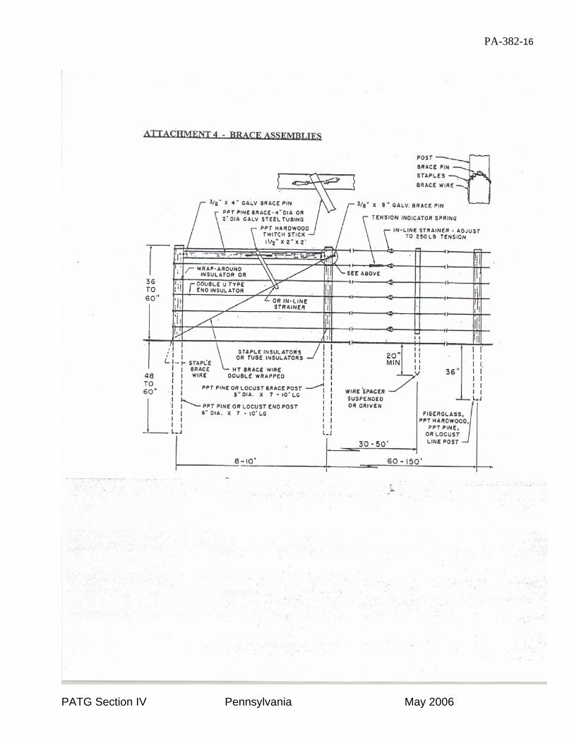
Brace assemblies.
A brace is a device, as in a supporting beam, that steadies or holds something together, (see Attachment 4).
Wooden
1. Single Braces are needed for 2 to 6 strands of high tensile fence. (see At-tachment 4).
2. Double span assemblies shall be used for 7 or more strands of wire. (see At-tachment 4).
3. Combination single and double brace spans shall be used on rolling land with a lot of curvature. Braces should be placed every as per manufacturer’s recommendation.
4. Brace assemblies are needed for Woven Wire, barbed wire, and any combination of woven, barbed, and high tensile wire.
Each single brace assembly component will have 2 brace pins that consist of galvanized steel rods* 3/8” X 9” and 3/8” X 4” long*.
Steel Steel galvanized pipe brace of the same length can replace a wooden brace. Diameter of gal-vanized steel brace should be a minimum of 2 inches in diameter.*
Bend assemblies.
When constructing wire fence along a curve or contour, post spacing is determined by the de-gree of bend. Curvature is measured by plac-ing 3 stakes, spaced 14 feet apart along the fence line. A string is then stretched between stake 1 and stake 3. The measurement taken is from stake 2 to the string.
Spacing of posts are determined as follows:
Curvature post spacing.
0 – 4 inches 14 feet 4 – 7 inches 12 feet 7 – 9 inches 10 feet 9 – 15 inches 8 feet
15 – or more inches 6 feet
Posts are to be placed equal distant from each other.
Tension.
1. For exterior wire fences, the tension should be maintained per manufactur-ers specification. An in-line strainer shall be on each of the strand, with a

PA382-6
Technical Guide Section IV Pennsylvania May 2006
spring tension indicator on one of the strands for monitoring purposes.
2. For interior wire fences, tension should be adequate to maintain the desired height and prevent wire from sagging between posts.
Wire spacing.
Height of constructed fence fabric is deter-mined by the species intended to control. The recommended heights for exterior, interior, electric and non-electric fences are shown in Table 1, 2, and 3.
MINIMUM HEIGHT GUIDELINES
SPECIES MINIMUM HEIGHT
Deer 94 inches Horses 48 inches People 48 inches Cattle 46 inches Goats 42 inches Sheep 36 inches Swine 36 inches
1. When using wire for exterior fences, the spacings in Table 1 are given as a guideline. Adjustments to the spacing may be made according to the manu-facturer’s recommendation.
2. When installing exterior fence for
goats a combination of high tensile woven wire and high tensile smooth wire shall be used. The woven wire shall be 32 inches tall and 2 strands of 12 ½ gauge electric high tensile wire shall be installed 6 “ and 12 “ above the woven wire. An additional single strand of 12 ½ gauge electric high ten-sile wire shall be installed, offset, on the inside of the wove wire 12 “ to 18” off the ground.
3. Fencing for Ag Waste Storage struc-
tures and ponds will vary. Chain Link fence will be used on top of concrete structures where animals or humans could readily access the top of the structure (for details see end for Chain
Link Fence Specification). Ag Waste Ponds can be fenced with high tensile fencing. A minimum of 8 strands of 12½ gauge wire with 2 strands electri-fied, on 15 ft post spacings, or 12 ½ gauge woven wire 42 “ high, with 1 strand 12 ½ gauge barbed wire or 1 strand of 12 ½ gauge electrified high tensile wire at 48” of height. For streams or water crosses where the depth of the stream is less than 1/3 the height of the fence the fence will run uninterrupted for streams of greater depth.
4. For streams or water crossings where the depth of the stream is less than 1/3 the height of the fence, the fence will run uninterrupted. For streams of greater depth end the main fence at the top of the streambank on each side with an appropriate end assem-bly. From separate posts driven next to the end posts, construct a separate section of fence across the water-course that shall be de-energized dur-ing high flow or flooding conditions. The only tie between the main fence and the section spanning the water-course shall be a single electrical con-nection.
The following guidelines are provided for the minimum number of wires on interior electric fences. MINIMUM INTERIOR WIRE GUIDELINES
SPECIES NO. OF WIRES Cattle 1 Cattle w/ calves 2 Horses 2 Sheep 2 Swine 2 Goats 3 Cattle (hard to control) 3
Recommendations of wire spacing for interior electric fences are given in Table 3. Adjust-ments can be made on wire spacings as per manufacturers recommendations.
Post Spacing.

PA382-7
Technical Guide Section IV Pennsylvania May 2006
Post spacing is determined by several factors such as number of strands, type of wire, soil type, terrain, and animals to be fenced. The following is a guideline for high tensile fence post spacing. Batten or stay spacing is speci-fied. If no battens are used, spacing will be that of rolling terrain. High Tensile Wire/Electrified Smooth Wire & Polywire Exterior Fence Number
wires No. Battens With Battens
1 - 3
30’ 40’ w/ battens @ 20’ max
4 - 5
20’ 30’ w/ battens @ 15’ max
6+ 16 ½’ 20’ w/ battens @ 10’ max
Interior Fence**
Number
wires 0 to 8%
Flat <8% & Various Rolling
1 – 2 50’ 40’ 3 - 4 35’ 30’ 5 – 6 25’ 20 ‘ 7 + 20’ 16 ½’
Post spacings can be greater based on manu-facturer's recommendations as long as live-stock are contained and the lifespan of the fence is guaranteed.
**Battens may be used on interior fence to maintain wire spacing, but post spacing will not change.
Board, woven wire, and exterior barbed wire post spacing shall be 16 ½’ maximum. Interior barbed wire post spacing shall be 20’ maxi-mum. Post spacing on chain link fence shall be 10’ maximum or as specified on construc-tion details or drawings.
INSTALLATION
Posts shall be established by driving, auguring, or hand digging. Fill material used in backfill-ing oversized dug holes, shall be clean soil material with little rock and hand tamped in 6 inch lifts. Cement can be used on oversized dug holes, instead of tamped, clean soil back-fill. When used, it shall be of a Portland mix type and sloped at the top to provide positive drainage. Braces are horizontal posts placed between two posts in a brace assembly. If using locust posts, nail in a diamond shape wherever possible to keep the wood from split-ting. Corner and gate posts shall be set a minimum of 4 feet deep below the soil surface.
Line and brace posts shall be set a minimum of 2 ½ feet deep below the soil surface.
Splices and Knots* (see Attachment 2)
Staples should be driven at an angle to the grain and not tight against the wire (see At-tachment 1).
For steel and notched fiberglass or plastic posts, clips should be hooked over the notch and wrapped around the line wire tightly to se-cure wire to the post (see Attachment 1).
Predrill boards to prevent splitting.
When wooden boards are used the surface shall be painted or treated with a wood pre-servative material for rot protection.
OPERATION AND MAINTENANCE
Regular inspection of fences shall be part of an ongoing management program. Inspection of fences after storm events is needed to facili-tate the function of the intended use of the fence. Check all fence systems for proper functional-ity and maintain tension to design specifica-tions. Where electric fences are used, periodi-cally check output of charger with a voltmeter. Annual clearing of weeds and brush under and near the fence systems will prolong life expec-tancy. Maintenance and repairs shall be per-

PA382-8
Technical Guide Section IV Pennsylvania May 2006
formed in a timely manner to maintain the de-sired control. ADDITIONAL CONDITIONS

PA-382C-9
PATG Section IV Pennsylvania May 2006
CONSTRUCTION SPECIFICATION
382C - CHAIN LINK FENCE
1. SCOPE
The work shall consist of furnishing materials and installing all components of the chain link fence as described in this specification and the drawings. 2. MATERIALS Fence fabric, posts, top rails, braces, gates and accessories shall conform to the requirements of this specification. Materials shall be as fol-lows except as otherwise specified in Section 8. Fabric: 2-inch mesh, g-gauge, minimum weight of zinc coating 1.8 ounces per square foot. (Double dipped galvanized). Posts: See Pipe Criteria Table, page PA-382C-SP2. Top Rail: See Pipe Criteria Table, page PA-382C-SP2. Braces: Same as Top Rails. Gates: Frame -See Pipe Criteria Table, page PA- 382C-SP2. Interior Braces -Same as top rail. 3. DIMENSIONS The fence shall have a minimum height of four feet or as shown on the drawings or otherwise specified in Section 8. The length of the fence shall be as shown in the drawings or as specified in Section 8.
4. INSTALLING FENCE POSTS Line posts shall be placed at intervals not exceeding eight feet measured from center to center of adjacent posts unless otherwise specified on the drawings or in Section 8. Posts shall be set in concrete a minimum of 12 inches. All posts shall be capped immediately after installation. Other installation details shall be as shown on the draw-ing or specified in Section 8. 5. INSTALLING WIRE FABRIC Fencing fabric shall not be stretched until at least three days after the posts are set in concrete walls or five days after the posts are set in concrete backfill. The fabric shall be stretched taut and securely fastened, by means of 9 gage tie clips, to the posts at intervals not exceeding 15 inches and to the top rails or tension wires at intervals not exceeding two feet. Care shall be taken to equalize the tension on each side of each post.
6. INSTALLING GATES Gate frames shall be fabricated and hung so that they sag no more than one percent (1%) of the gate width.

PA-382-10
PATG Section IV Pennsylvania May 2006
PIPE CRITERIA For
CHAIN LINK FENCE
Outside Diameter (Inches) Trade Size Nominal Pipe Size Actual Size Standard Pipe (Schedule 40) Wall Thickness (Inches) Weight (lb/ft) Zinc Coating (oz/ft2) High Strength Pipe (Min. 50,000 psi Yield Strength) Wall Thickness (Inches) Weight (lb/ft) Zinc Coating (oz/ft2)
Top Rail & Gate Frame 1 5/8 1 1/4 1.660 0.112 1.82 1.8 0.065 1.107 0.9
Line Post 2 1 ½ 1.900 0.145 2.72 1.8 0.090 1.74 0.9
End & Gate Post 2 ½ 2 2.375 0.154 3.65 1.8 0.130 3.12 0.9
NOTE: Outside diameter requirements are the same regardless of pipe material. Pipe material must be either Standard Pipe (Schedule 40) or High Strength (Minimum 50,000 psi Yield Strength) meeting the wall thickness, weight, and zinc coating requirements shown in the table for that type of pipe.

PA-382-11
PATG Section IV Pennsylvania May 2006
7. MEASUREMENT AND PAYMENT Method 1 Payment shall be made at the con-tract lump sum price. Such payment shall constitute full compensation for all labor, equipment, tools, material and all other items necessary and incidental to the completion of the work. Method 2 Payment shall be made to the nearest foot of installed length of fence, in-cluding gates. Such payment shall constitute full compensation for all labor, equipment, tools, material and all other items necessary and incidental to the completion of the work. All methods Compensation for any item of work described in the contract but not listed in the bid schedule will be included in the pay-ment for the work to which it is made subsidi-ary in Section 8. 8. ADDITIONAL CONDITIONS WHICH APPLY TO THIS PROJECT ARE:

PA382 - 12
Technical Guide Section IV Pennsylvania May 2006
TABLE 1. EXTERIOR NON-ELECTRIC SMOOTH WIRE FENCE SPACING TYPE STRAND WIRE SPACING FROM THE BOTTOM IN INCHES HEIGHT Cattle(feed lot) 10 10 - 4 - 4 - 4 - 5 - 5 - 5 - 5 - 5 - 5 52" Horses 10 6 - 4 - 4 - 4 - 5 - 5 - 5 - 5 - 5 - 5 48" Cattle + calves 8 4 - 5 - 5 - 5 - 6 - 6 - 7 - 8 46" Cattle 6 14 - 5 - 6 - 6 - 7 - 8 46" Sheep 6 5 - 5 - 5 - 5 - 8 - 8 36" Swine 6 4 - 5 - 5 - 6 - 8 - 8 36" TABLE 2. EXTERIOR ELECTRIC SMOOTH WIRE FENCE SPACING TYPE STRAND WIRE SPACING FROM THE BOTTOM IN INCHES HEIGHT Cattle(feed lot) 7 10 - 6 - 6 - 6 - 8 - 8 - 8 52" Horses 6 10 - 8 - 8 - 8 - 8 - 6 48" Cattle + calves 5 10 - 8 - 8 - 10 - 10 46" Cattle 4 10 - 12 - 12 - 12 46" Sheep 5 6 - 6 - 8 - 8 - 8 36" Swine 5 6 - 6 - 8 - 8 - 8 36"
TABLE 3. INTERIOR ELECTRIC FENCE SPACING NUMBER OF WIRES WIRE SPACING FROM THE BOTTOM IN INCHES* HEIGHT
1 30(+) 30" 2 16(-) - 16(+) 32" 3 12(-) - 10(+) - 14(+) 36" 4 12(-) - 10(+) - 8(-) - 10(+) 40" 5 10(-) - 8(-) - 8(+) - 8(-) - 10(+) 44"
* Suggested Charging Sequence: (+) = charged wire (-) = ground wire

PA-382-13
PATG Section IV Pennsylvania May 2006

PA-382-14
PATG Section IV Pennsylvania May 2006

PA-382-15
PATG Section IV Pennsylvania May 2006
PA-382-16
PATG Section IV Pennsylvania May 2006