anchoring products/plugs8 - mettex - engineers … type ftp plastic page 8-23 fischer installation...
TRANSCRIPT

8-1
Anchoring products/plugs8
8
Page 8-3
MAXXFAST UniFast
Page 8-4
Nylon
Page 8-5
FISCHER Type S
Page 8-7
FISCHER Assortment
Page 8-8
FISCHER Type MS
Page 8-9
FISCHER Type SX
Page 8-11
MAXXFAST MultiFast
Page 8-12
FISCHER Type UX/UX-R
Page 8-13
MAXXFAST 4Fast
Page 8-14
FISCHER Universal type FU
Page 8-15
MOLLY
Page 8-16
MOLLY Hand plier
Page 8-17
FISCHER Type HM/HMS
Page 8-18
FISCHER Installation tools
Page 8-19
SPIT Driva
Page 8-20
FISCHER Type GB
Page 8-21
FISCHER Type GK/GKS
Page 8-22
FISCHER Type FTP Steel
Page 8-22
FISCHER Type FTP Plastic
Page 8-23
FISCHER Installation tool FTP
Page 8-24
FISCHER Toggle plug
Page 8-25
SPIT Type SDA
Page 8-26
FISCHER Type FNH
Page 8-27
MAXXFAST HammerFast
Page 8-28
FISCHER Type N-Z
Page 8-30
FISCHER Type N-FZ
Page 8-31
FISCHER Type N-D
Page 8-32
FISCHER Type SXS
Page 8-34
FISCHER Type F-S
Page 8-35
FISCHER Type F-M
Page 8-36
FISCHER Type FUR-T
Page 8-37
FISCHER Type FUR-SS
Page 8-38
FISCHER Type SXR-T
Page 8-39
FISCHER Type FFS
Page 8-40
FISCHER Type JS
Page 8-41
FISCHER Type S/J/S
Page 8-42
FISCHER Cover cap
Page 8-43
Expanding plug
Page 8-44
FISCHER Type M
Page 8-45
FISCHER Type PA
Page 8-46
SPIT Type SA
Page 8-47
Installation tool SA
Page 8-48
FISCHER Type EA II
Page 8-50
Installation tool for EA II
Page 8-51
FISCHER Type FHY
Page 8-52
FISCHER Type FSA-S
Page 8-53NEN ≈2316
With conical nut
Page 8-54
With projecting bolt
Page 8-55
With hexagon screw
Page 8-56
Self tapping screw anchor type BT

8-2
Anchoring products/plugs8
8
Page 8-58
MAXXFAST ThruFast-ThruMaxx
Page 8-61
SPIT Type FIX II
Page 8-63
FISCHER Type FBN II
Page 8-66
FISCHER Type FAZ II
Page 8-68
FISCHER Type FH II-B
Page 8-70
FISCHER Type FH II-S
Page 8-72
FISCHER Type FZA
Page 8-73
FISCHER Tool
Page 8-75
LIEBIG Type B
Page 8-77
LIEBIG Type S
Page 8-78
LIEBIG Type AB
Page 8-79
MAXXFAST Chemical fixing
Page 8-80
SPIT Type Maxima
Page 8-82
FISCHER Type RG M
Page 8-83
FISCHER Setting tool
Page 8-84
Capsule
Page 8-86
Injection cartridge
Page 8-88
Injection tool
Page 8-89
MAXXFAST Anchoring
Page 8-91
FISCHER Injection anchor sleeve
Page 8-92
FISCHER Type RG MI
Page 8-93DIN 529 ANEN 2328 A
Type A
Page 8-94DIN 529 ENEN 2328 E
Type E
Page 8-95
With hook 50 or 100mm
Page 8-97
Shuttering
Page 8-97
Shuttering
Page 8-99
VEMO Type 1550
Page 8-100
VEMO Type 995G
Page 8-101
VEMO Type 1036
Page 8-102
VEMO Type 1130
Page 8-103
VEMO Type 1551
Page 8-103
VEMO Type 2244

8-3121 - www.fabory.com
8
MAXXFAST Wall plug UniFast30500
MAXXFAST Wall plug UniFast
Wall plug UniFast
Technical datad 5 6 7 8 10 12
L 25 30 30 40 50 60
Drill ø 5 6 7 8 10 12
Drill depth (min.) 35 40 40 50 60 70
Application in combination with:
Chipboard screws 2,5-4 3,5-4 4-4,5 4,5-6 6-8 8-10
Pull-out force for wood screw in kN
Concrete ≥ C20/25 0,42 0,64 0,76 0,90 1,80 2,10
Brick ≥ Mz12 0,36 0,50 0,64 0,80 0,88 0,90
30500 MAXXFAST Wall plug UniFast MF50
Material Plastic Nylon (polyamide)Colour GreyPackaging Standard
d Art.number d Art.number d Art.number
5MM 100 30500.050.0016MM 100 30500.060.001
7MM 100 30500.070.0018MM 100 30500.080.001
10MM 50 30500.100.00112MM 25 30500.120.001

8-4 121 - www.fabory.com
8
Wall plug63158
Wall plug63158
Wall plug63159
Wall plug
Wall plug
Technical datad 4 5 6 7 8 10 12 14
L 20 25 30 37 40 50 60 80
Drill ø 4 5 6 7 8 10 12 14
Drill depth (min.) 25 35 40 45 55 70 80 100
Application in combination with:
Wood-/Hexagon head wood screws ø 2-3 3-4,5 4,5-5 4,5-5,5 5-6 6-8 8-10 10-12
Assembly sequence
Article groupsMaterial Colour Packaging Code Page
Plastic Nylon Grey Standard 63158 8-4
Plastic Nylon Grey Large 63159 8-4
63158 Wall plug N05A
Material Plastic Nylon (polyamide)Colour GreyPackaging Standard
d Art.number d Art.number d Art.number
4MM 200 63158.040.0015MM 100 63158.050.0016MM 100 63158.060.001
7MM 100 63158.070.0018MM 100 63158.080.00110MM 50 63158.100.001
12MM 25 63158.120.00114MM 20 63158.140.001
63159 Wall plug N05A
Material Plastic Nylon (polyamide)Colour GreyPackaging Large
d Art.number d Art.number d Art.number
5MM 1000 63159.050.0016MM 500 63159.060.001
8MM 250 63159.080.00110MM 200 63159.100.001
12MM 100 63159.120.001
8-5121 - www.fabory.com
8
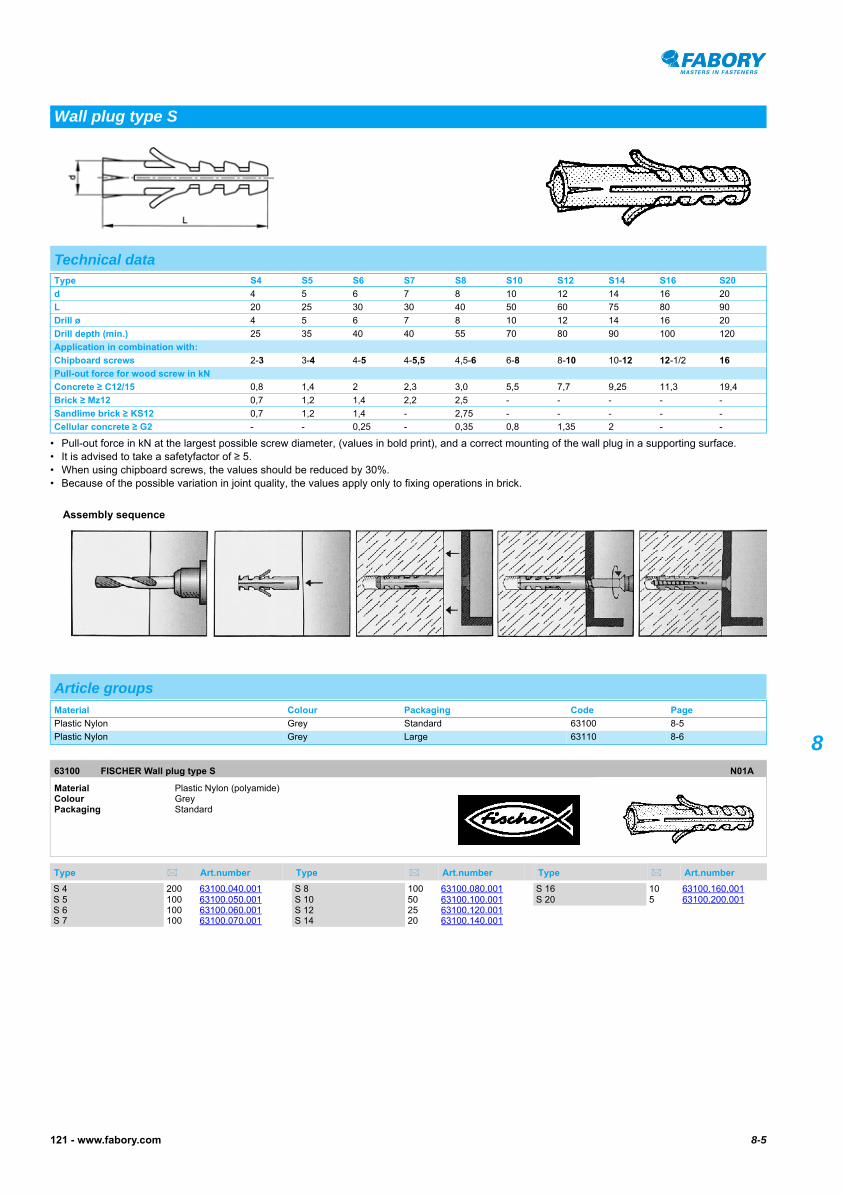
• Pull-out force in kN at the largest possible screw diameter, (values in bold print), and a correct mounting of the wall plug in a supporting surface.• It is advised to take a safetyfactor of ≥ 5.• When using chipboard screws, the values should be reduced by 30%.• Because of the possible variation in joint quality, the values apply only to fixing operations in brick.
FISCHER Wall plug type S63100
FISCHER Wall plug type S
Wall plug type S
Technical dataType S4 S5 S6 S7 S8 S10 S12 S14 S16 S20
d 4 5 6 7 8 10 12 14 16 20
L 20 25 30 30 40 50 60 75 80 90
Drill ø 4 5 6 7 8 10 12 14 16 20
Drill depth (min.) 25 35 40 40 55 70 80 90 100 120
Application in combination with:
Chipboard screws 2-3 3-4 4-5 4-5,5 4,5-6 6-8 8-10 10-12 12-1/2 16
Pull-out force for wood screw in kN
Concrete ≥ C12/15 0,8 1,4 2 2,3 3,0 5,5 7,7 9,25 11,3 19,4
Brick ≥ Mz12 0,7 1,2 1,4 2,2 2,5 - - - - -
Sandlime brick ≥ KS12 0,7 1,2 1,4 - 2,75 - - - - -
Cellular concrete ≥ G2 - - 0,25 - 0,35 0,8 1,35 2 - -
Assembly sequence
Article groupsMaterial Colour Packaging Code Page
Plastic Nylon Grey Standard 63100 8-5
Plastic Nylon Grey Large 63110 8-6
63100 FISCHER Wall plug type S N01A
Material Plastic Nylon (polyamide)Colour GreyPackaging Standard
Type Art.number Type Art.number Type Art.number
S 4 200 63100.040.001S 5 100 63100.050.001S 6 100 63100.060.001S 7 100 63100.070.001
S 8 100 63100.080.001S 10 50 63100.100.001S 12 25 63100.120.001S 14 20 63100.140.001
S 16 10 63100.160.001S 20 5 63100.200.001

8-6 121 - www.fabory.com
8
FISCHER Wall plug type S63110
FISCHER Wall plug type S
63110 FISCHER Wall plug type S N01A
Material Plastic Nylon (polyamide)Colour GreyPackaging Large
Type Art.number Type Art.number Type Art.number
S 5 1000 63110.050.001 S 6 500 63110.060.001 S 8 250 63110.080.001
8-7121 - www.fabory.com
8
FISCHER Assortment box wall plugs type S63150
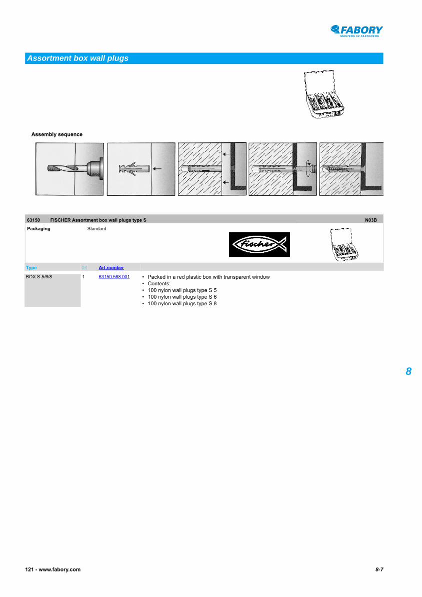
FISCHER Assortment box wall plugs type S
Assortment box wall plugs
63150 FISCHER Assortment box wall plugs type S N03B
Packaging Standard
Type Art.number
Assembly sequence
BOX S-5/6/8 1 63150.568.001 • Packed in a red plastic box with transparent window• Contents:• 100 nylon wall plugs type S 5• 100 nylon wall plugs type S 6• 100 nylon wall plugs type S 8

8-8 121 - www.fabory.com
8
• Wall plug type MS is applicable with metric threaded fasteners.• It is advised to take a safetyfactor: ≥ 7.
FISCHER Wall plug type MS63160
FISCHER Wall plug type MS
Wall plug type MS
Technical dataType M6-S M8-S M10-S M12-S
d 8 10 14 16
L 40 50 70 80
Drill ø 8 10 14 16
Drill depth (min.) 55 70 90 100
Pull-out force in kN
Concrete C12/15 2,1 3,8 4,6 7,4
Brick Mz12 1,7 2,3 3,2 5,5
Sandlime brick ≥ KS12 1,7 2,3 3 5
63160 FISCHER Wall plug type MS N03B
Thread Metric threadMaterial Plastic Nylon (polyamide)Colour BeigePackaging Standard
Type Art.number Type Art.number Type Art.number
Assembly sequence
M6 S 100 63160.060.001M8 S 50 63160.080.001
M10 S 20 63160.100.001M12 S 10 63160.120.001

8-9121 - www.fabory.com
8
• Allowable load in kN at the largest possible screw diameter, (values in bold print), and a correct mounting of the wall plug in a supporting surface.• When using chipboard screws, the values should be reduced by 30%.• Because of the possible variation in joint quality, the values apply only to fixing operations in brick.
FISCHER Wall plug type SX63120
FISCHER Wall plug type SX
Wall plug type SX
Technical dataType SX 4 SX 5 SX 6 SX 6-L SX 8 SX 8-L SX 10 SX 12 SX 14 SX 16
d 4 5 6 6 8 8 10 12 14 16
L 20 25 30 50 40 65 50 60 70 80
Drill ø 4 5 6 6 8 8 10 12 14 16
Drill depth (min.) 25 35 40 60 50 75 70 80 90 100
Application in combination with:
Chipboard screws 2-3 3-4 4-5 4-5 4,5-6 4,5-6 6-8 8-10 10-12 12-1/2
Allowable load in kN
Concrete ≥ C20/25 - 0,29 0,7 0,7 0,71 0,71 1,21 1,71 2,01 2,01
Brick ≥ Mz12 - 0,23 0,31 0,31 0,59 0,59 0,64 0,71 0,8 0,8
Sandlime brick ≥ KS12 - 0,29 0,5 0,5 0,6 0,6 1,21 1,71 2,01 2,01
Cellular concrete ≥ G2 - 0,03 0,03 0,03 0,04 0,04 0,09 0,14 0,31 0,31
Cellular concrete ≥ G4 - 0,09 0,09 0,09 0,14 0,14 0,29 0,44 0,49 0,49
Ventilation stone ≥ Hlz12, ρ ≥ 1,0 kg/dm3 - 0,07 0,07 0,07 0,17 0,17 0,17 0,26 0,44 0,44
Hollow sandlime brick KSL12 - 0,17 0,3 0,3 0,33 0,33 0,29 0,35 0,31 0,31
Assembly sequence
Article groupsMaterial Colour Packaging Code Page
Plastic Nylon Grey SX Standard 63120 8-9
Plastic Nylon Grey SX-L Standard 63121 8-10
63120 FISCHER Wall plug type SX N01A
Material Plastic Nylon (polyamide)Colour GreyPackaging Standard
Type Art.number Type Art.number Type Art.number
SX4 200 63120.040.001SX5 100 63120.050.001SX6 100 63120.060.001
SX8 100 63120.080.001SX10 50 63120.100.001SX12 25 63120.120.001
SX14 20 63120.140.001SX16 10 63120.160.001
8-10 121 - www.fabory.com
8
FISCHER Wall plug type SX-L63121
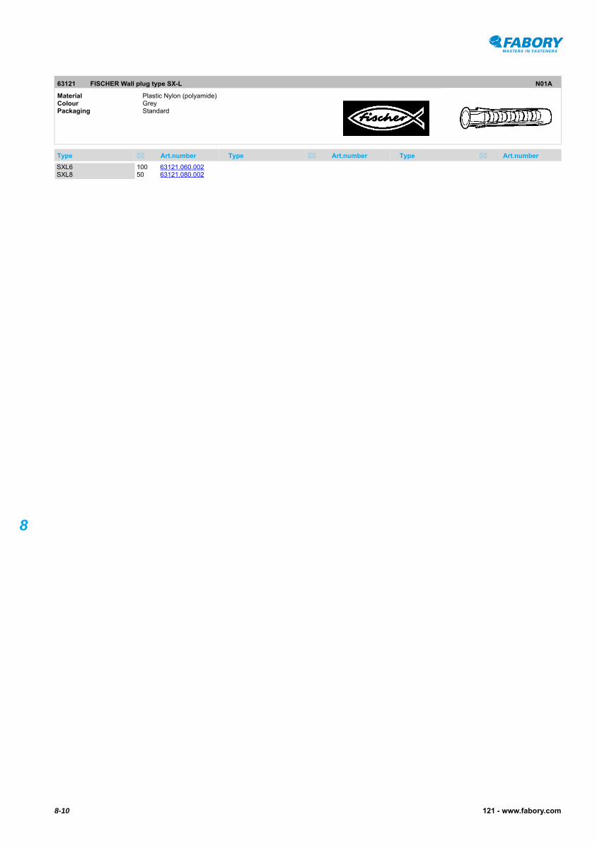
FISCHER Wall plug type SX-L
63121 FISCHER Wall plug type SX-L N01A
Material Plastic Nylon (polyamide)Colour GreyPackaging Standard
Type Art.number Type Art.number Type Art.number
SXL6 100 63121.060.002SXL8 50 63121.080.002
8-11121 - www.fabory.com
8
MAXXFAST Wall plug MultiFast30502
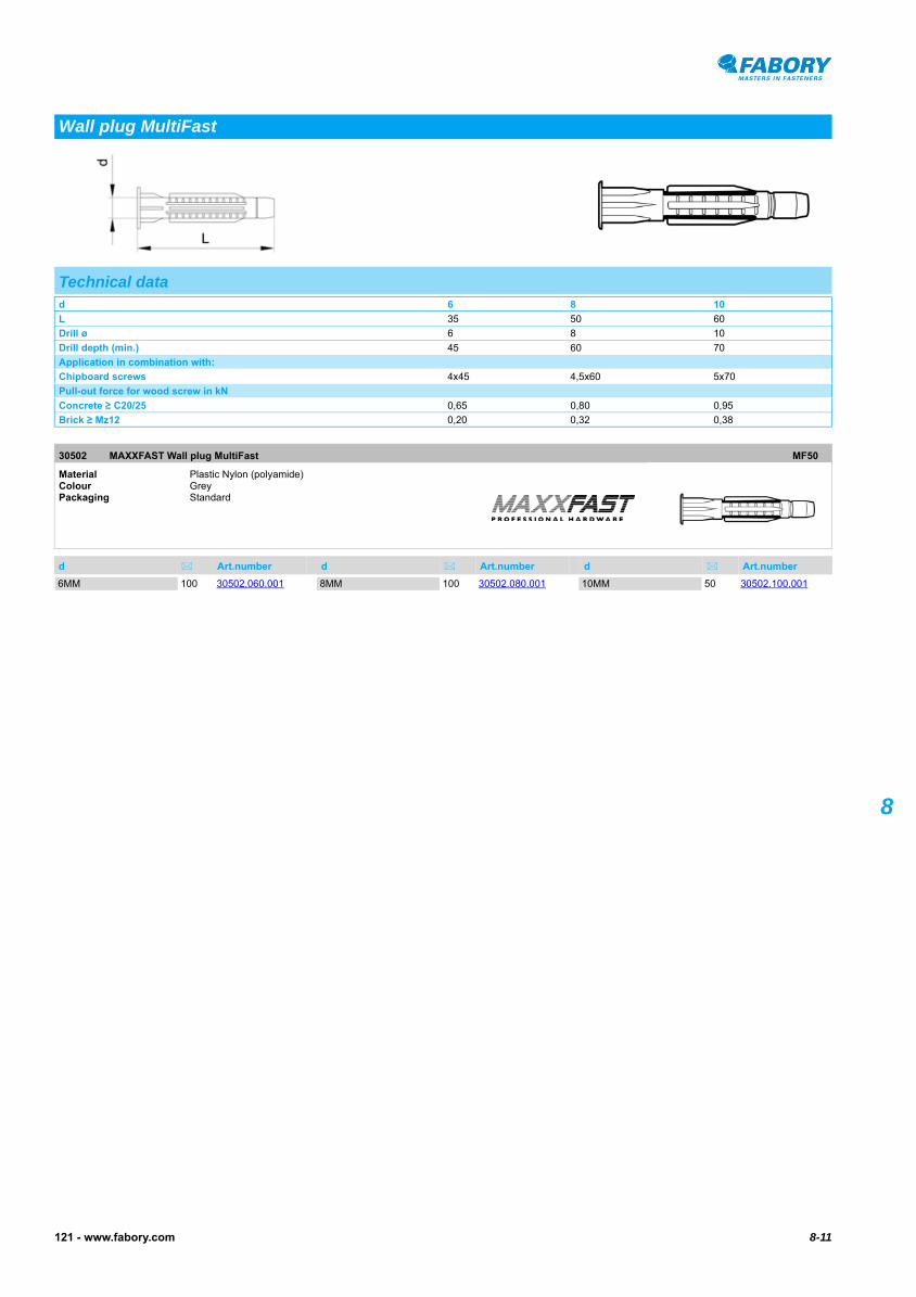
MAXXFAST Wall plug MultiFast
Wall plug MultiFast
Technical datad 6 8 10
L 35 50 60
Drill ø 6 8 10
Drill depth (min.) 45 60 70
Application in combination with:
Chipboard screws 4x45 4,5x60 5x70
Pull-out force for wood screw in kN
Concrete ≥ C20/25 0,65 0,80 0,95
Brick ≥ Mz12 0,20 0,32 0,38
30502 MAXXFAST Wall plug MultiFast MF50
Material Plastic Nylon (polyamide)Colour GreyPackaging Standard
d Art.number d Art.number d Art.number
6MM 100 30502.060.001 8MM 100 30502.080.001 10MM 50 30502.100.001

8-12 121 - www.fabory.com
8
FISCHER Plug universal UX63276
FISCHER Plug universal UX63276
FISCHER Plug universal UX-R63277
FISCHER Plug universal UX-R
Plug universal UX/UX-R
Technical dataType UX (R) 6 UX (R) 8 UX (R) 10 UX 12 UX 14
Drill ø 6 8 10 12 14
Drill depth (min.) 45 60 75 85 95
Material thickness (min.) 9,5 9,5 12,5 - -
Plug length 35 50 60 70 75
Chipboard screws ø 4-5 4,5-6 6-8 8-10 10-12
Article groupsMaterial Packaging Code Page
Plastic UX Standard 63276 8-12
Plastic UX-R Standard 63277 8-12
63276 FISCHER Plug universal UX N03A
Material Plastic Packaging Standard
Type Art.number Type Art.number Type Art.number
UX 6 100 63276.060.001UX 8 100 63276.080.001
UX 10 50 63276.100.001UX 12 25 63276.120.001
UX 14 20 63276.140.001
63277 FISCHER Plug universal UX-R N03A
Material Plastic Packaging Standard
Type Art.number Type Art.number Type Art.number
6 UX-R 100 63277.060.001 8 UX-R 100 63277.080.001 10 UX-R 50 63277.100.001

8-13121 - www.fabory.com
8
MAXXFAST Wall plug 4Fast30505
MAXXFAST Wall plug 4Fast
Wall plug 4Fast
Technical datad 5 6 8 10 12
L 25 30 40 50 60
Drill ø 5 6 8 10 12
Drill depth (min.) 30 50 50 60 70
Application in combination with:
Chipboard screws 4x30 4,5x50 5x50 6x60 10x70
Pull-out force for wood screw in kN
Concrete ≥ C20/25 0,80 1,10 1,20 1,86 2,60
Brick ≥ Mz12 0,46 0,90 1,00 1,10 1,20
30505 MAXXFAST Wall plug 4Fast MF50
Material Plastic Nylon (polyamide)Colour GreyPackaging Standard
d Art.number d Art.number d Art.number
5MM 100 30505.050.0016MM 100 30505.060.001
8MM 100 30505.080.00110MM 50 30505.100.001
12MM 25 30505.120.001

8-14 121 - www.fabory.com
8
• Pull-out force in kN at the largest possible screw diameter, (values in bold print), and a correct mounting of the plug in a supporting surface.• It is advised to take a safetyfactor of ≥ 7.
FISCHER Universal fixing type FU63270
FISCHER Universal fixing type FU
Universal fixing
Technical dataType FU 6x35 FU 6x45 FU 8x50 FU 10x60
d 6 6 8 10
L 35 45 50 60
Drill ø 6 6 8 10
Drill depth (min.) 45 55 60 70
Material thickness (min.) 6 6 6 6
Application in combination with:
Chipboard screws 3-3,5 3-3.5 4-4,5 5-6
Pull-out force for wood screw/
Pull-out force for chipboard screws
Concrete C20/25 2/1 2/1 4/2 6/3
Brick Mz12 1,8/0,6 1,8/0,6 3,5/1,4 5,5/1,7
Sandlime brick KS12 1,8/0,8 1,8/0,8 3,5/1,7 5,5/2,1
Pumice grit V2 0,75/0,2 0,75/0,2 1,5/0,45 1,6/0,65
Cellular concrete PB2, PP2 (G2) 0,25/0,2 0,25/0,2 0,65/0,6 0,9/0,8
Cellular concrete PB4, PP4 (G4) 0,9/0,5 0,9/0,5 1,6/1,1 1,9/1,7
Ventilation stone Hlz12 -/0,9 -/0,9 -/1,1 -/1,5
Hollow sandlime brick KSL6 -/1 -/1 -/1,5 -/2
Plasterboard 10mm -/0,4 -/0,4 -/0,45 -/0,45
Chipboard 10mm -/1,2 -/1,2 -/1,4 -/2
63270 FISCHER Universal fixing type FU N03A
Material Plastic Nylon (polyamide)Colour GreyPackaging Standard
Type Art.number Type Art.number Type Art.number
Assembly sequence
FU 6X35 50 63270.060.035FU 6X45 50 63270.060.045
FU 8X50 50 63270.080.050FU 10X60 25 63270.100.060
8-15121 - www.fabory.com
8
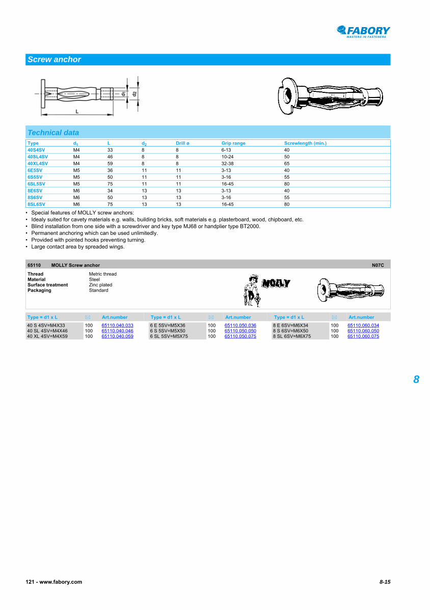
• Special features of MOLLY screw anchors:• Idealy suited for cavety materials e.g. walls, building bricks, soft materials e.g. plasterboard, wood, chipboard, etc.• Blind installation from one side with a screwdriver and key type MJ68 or handplier type BT2000.• Permanent anchoring which can be used unlimitedly.• Provided with pointed hooks preventing turning.• Large contact area by spreaded wings.
MOLLY Screw anchor65110
MOLLY Screw anchor
Screw anchor
Technical dataType d1 L d2 Drill ø Grip range Screwlength (min.)
40S4SV M4 33 8 8 6-13 40
40SL4SV M4 46 8 8 10-24 50
40XL4SV M4 59 8 8 32-38 65
6E5SV M5 36 11 11 3-13 40
6S5SV M5 50 11 11 3-16 55
6SL5SV M5 75 11 11 16-45 80
8E6SV M6 34 13 13 3-13 40
8S6SV M6 50 13 13 3-16 55
8SL6SV M6 75 13 13 16-45 80
65110 MOLLY Screw anchor N07C
Thread Metric threadMaterial Steel Surface treatment Zinc platedPackaging Standard
Type = d1 x L Art.number Type = d1 x L Art.number Type = d1 x L Art.number
40 S 4SV=M4X33 100 65110.040.03340 SL 4SV=M4X46 100 65110.040.04640 XL 4SV=M4X59 100 65110.040.059
6 E 5SV=M5X36 100 65110.050.0366 S 5SV=M5X50 100 65110.050.0506 SL 5SV=M5X75 100 65110.050.075
8 E 6SV=M6X34 100 65110.060.0348 S 6SV=M6X50 100 65110.060.0508 SL 6SV=M6X75 100 65110.060.075

8-16 121 - www.fabory.com
8
MOLLY Hand plier
Hand plier
65210 MOLLY Hand plier N07C
Packaging Standard
Type Art.number Type Art.number Type Art.number
Assembly sequence
MT 2000 1 65210.001.775

8-17121 - www.fabory.com
8
• HM4x32/ HM5x37/ HM6x37/ HM6x80 delivered without screw.• HM8x55SS With hexagon head screw, assembly only by using professional nippers HM Z 1.
FISCHER Cavity fixing type HM/HM-S63240
FISCHER Cavity fixing type HM/HM-S
Cavity fixing
Technical dataType d L Screw size Drill ø Drill depth (min.) Material thickness (max.) Structural part thickness (max.)
HM 4x32 M4 32 - 8 42 3-13 16
HM 4x32 S M4 32 M4X40 8 42 3-13 16
HM 4x46 S M4 46 M4X2 8 56 5-18 23
HM 4x59 S M4 59 M4X66 8 69 35-42 16
HM 5x37 S M5 37 M5X45 11 47 6-15 19
HM 5x52 S M5 52 M5X60 11 62 7-21 24
HM 5x65 S M5 65 M5X73 11 75 20-34 24
HM 6x37 M6 37 - 13 47 6-15 14
HM 6x37 S M6 50 M6X60 13 62 10-21 24
HM 6x52 S M6 52 M6X60 13 62 10-21 24
HM 6x65 S M6 65 M6X70 13 75 20-34 24
HM 6x80 M6 80 - 13 90 38-50 24
HM 6x80 S M6 80 M6X88 13 90 38-50 24
HM 8x55 SS M8 55 M8X60 13 65 10-21 24
63240 FISCHER Cavity fixing type HM/HM-S N03A
Thread Metric threadMaterial Steel Surface treatment Zinc platedPackaging Standard
Type Art.number Type Art.number Type Art.number
Assembly sequence
HM4X32S 50 63240.040.132HM4X46S 50 63240.040.146HM4X54S 50 63240.040.154HM4X59S 50 63240.040.159
HM5X37S 50 63240.050.137HM5X52S 50 63240.050.152HM5X65S 50 63240.050.165HM6X37S 50 63240.060.137
HM6X52S 50 63240.060.152HM6X65S 50 63240.060.165HM6X80S 50 63240.060.180HM8X55S 50 63240.080.155

8-18 121 - www.fabory.com
8
FISCHER Installation tool63248
FISCHER Installation tool
Cavity fixing installation tool
63248 FISCHER Installation tool N03A
Packaging Standard
Type Art.number
HMZ 2 1 63248.000.100 • DIY nipper• Suitable for the installation of FISCHER cavity fixings
HMZ 1 1 63248.000.105 • Professional nipper• Suitable for the installation of FISCHER cavity fixings

8-19121 - www.fabory.com
8DRIVA Self-drilling anchor for plasterboard70880
• DRIVA self-drilling anchors are made of Zamac 3 (zinc alloy), type TP 12 with zinc plated screws for back panels and type TF 27 with zinc plated countersunk screw.
• The named values are successively applicable for plasterboard 10 mm, plasterboard 13 mm and cellular concrete (6 mm pre-drill).• It is advised to take a safetyfactor ≥ 5, due to the many different qualities of plasterboards.DRIVA Self-drilling anchor for plasterboard70880
DRIVA PLUS Self-drilling anchor for plasterboard70882
DRIVA PLUS Self-drilling anchor for plasterboard70882
• DRIVA PLUS self-drilling self-setting toggle anchors are made of Zamac 3 (zinc alloy). Delivered with zinc plated screws, specially developed for DRIVA PLUS self-drilling anchors.
• It is advised to take a safetyfactor ≥ 5, due to the many different qualities of plasterboards.
Self-drilling anchor for plasterboard
Technical dataType TP 12 TP 12-PLUS TP 27 TP 30-PLUS
L 31 39 31 39
d1 13 10,5 13 10,5
d2 6 15,5 6 15,5
Grip range 0-12 0-12 12-27 5-30
Material thickness (min.) 10 10-13 10 10-13
Screw size 4,5x35 4,5x45 4,5x50 4,5x60
No. Pozidriv (Z) 2 2 2 2
Assembly data
Pull-out force in N 300/400/350 600 300/400/350 600
Shear strength min. in N 900 1400 900 1400
Edge distance tensile in cm 2,5/2,5/3,5 - 2,5/2,5/3,5 -
Edge distance shear in cm 3,5/3,5/5 - 3,5/3,5/5 -
Distance between centrelines tensile in cm 3,5/3,5/5 - 3,5/3,5/5 -
Distance between centrelines shear in cm 4,5/4,5/7 - 4,5/4,5/7 -
Assembly sequence
Article groupsMaterial Surface treatment Packaging Code Page
Zamac 3 Zipl Standard 70880 8-19
Zamac 3 Zipl PLUS Standard 70882 8-19
70880 DRIVA Self-drilling anchor for plasterboard N05A
Material Zamac 3 Surface treatment Zinc platedPackaging Standard
Type Art.number Type Art.number Type Art.number
TP 12 100 70880.120.001 TF 27 100 70880.270.001
70882 DRIVA PLUS Self-drilling anchor for plasterboard N05A
Material Zamac 3 Surface treatment Zinc platedPackaging Standard
Type Art.number Type Art.number Type Art.number
TP 12-PLUS 100 70882.120.001

8-20 121 - www.fabory.com
8
• Allowable load in tensile zone in roof- and ceiling panels.
FISCHER Aircrete anchor type GB63300
FISCHER Aircrete anchor type GB
Aircrete anchor
Technical dataType GB8 GB10 GB14
L 50 55 75
Drill ø 8 10 14
Drill depth (min.) 60 65 90
Screw ø 5 7 10
Allowable load in kN
Cellular concrete ≥ PB2, PP2 (G2) 0,2 0,25 0,4
Cellular concrete ≥ PB4, PP4 (G4) 0,4 0,6 0,9
Cellular concrete ≥ PB3,3 (GB3,3) 0,3 0,5 0,8
Cellular concrete ≥ P4,4 (GB4,4) 0,4 0,6 0,9
Cellular concrete ≥ P3,3 (GB3,3) - - 0,3
63300 FISCHER Aircrete anchor type GB N03B
Material Plastic Nylon (polyamide)Colour GreyPackaging Standard
Type Art.number Type Art.number Type Art.number
Assembly sequence
GB 8 25 63300.080.001 GB 10 20 63300.100.001 GB 14 10 63300.140.001

8-21121 - www.fabory.com
8
• GKS Supplied with installation tool and plasterboard screws.• GK Min. screw length = length of plug 22 mm + thickness of building component.
FISCHER Plasterboard fixing type GK/GKS63261
FISCHER Plasterboard fixing type GK/GKS
Plasterboard fixing
Technical dataType GK GKS
L 22 22
Cavity depth (min.) 25 25
Screw ø 4-5 4,5x35
Grip range - 13
Allowable load in kN
Plasterboard 9,5mm 0,07 0,07
Plasterboard 12,5mm 0,08 0,08
Plasterboard ≥ 2x12,5mm 0,11 0,11
63261 FISCHER Plasterboard fixing type GK/GKS N03A
Material Plastic Nylon (polyamide)Colour GreyPackaging Standard
Type Art.number Type Art.number Type Art.number
Assembly sequence
GK 4,0X35 100 63261.040.035GKS 4,5X35 50 63261.045.035

8-22 121 - www.fabory.com
8
FISCHER Turbo anchor FTP steel63309
FISCHER Turbo anchor FTP steel
FISCHER Turbo anchor FTP plastic63310
FISCHER Turbo anchor FTP plastic
Turbo anchor FTP steel
Technical dataType M6 M8 M10
Screw-in depth max. 20 25 30
Overall length 50 60 70
Depth of drilled hole to deepest point 60 70 80
Drill ø 8 10 12
Screw ø M6 M8 M10
63309 FISCHER Turbo anchor FTP steel N03A
Material Steel Packaging Standard
Type Art.number Type Art.number Type Art.number
M6 25 63309.060.001 M8 25 63309.080.001 M10 25 63309.100.001
Turbo anchor FTP plastic
Technical dataType K4 K6 K8 K10
Screw-in depth max. 35 40 45 50
Overall length 50 50 60 70
Depth of drilled hole to deepest point 60 60 70 80
Drill ø 8 8 10 12
Wood screws ø 4-4,5 5-6 7-8 9-10
Screw ø M4 M5-6 M8 M8-10
63310 FISCHER Turbo anchor FTP plastic N03A
Material Plastic Packaging Standard
Type Art.number Type Art.number Type Art.number
K4 25 63310.040.001K6 25 63310.060.001
K8 25 63310.080.001K10 10 63310.100.001
8-23121 - www.fabory.com
8
FISCHER Installation tool FTP steel63312
FISCHER Installation tool FTP steel63312
FISCHER Installation tool FTP plastic63313
FISCHER Installation tool FTP plastic
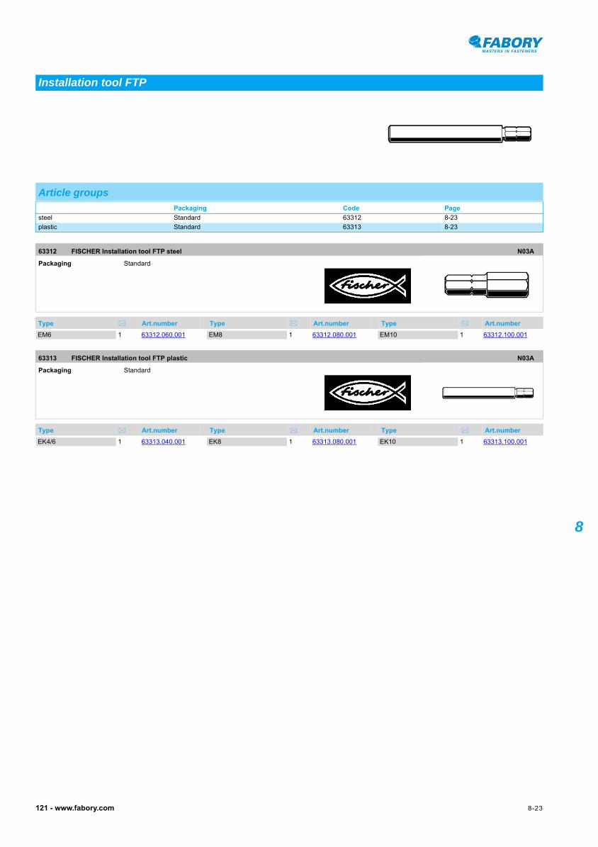
Installation tool FTP
Article groupsPackaging Code Page
steel Standard 63312 8-23
plastic Standard 63313 8-23
63312 FISCHER Installation tool FTP steel N03A
Packaging Standard
Type Art.number Type Art.number Type Art.number
EM6 1 63312.060.001 EM8 1 63312.080.001 EM10 1 63312.100.001
63313 FISCHER Installation tool FTP plastic N03A
Packaging Standard
Type Art.number Type Art.number Type Art.number
EK4/6 1 63313.040.001 EK8 1 63313.080.001 EK10 1 63313.100.001

8-24 121 - www.fabory.com
8
• It is advised to take a safetyfactor: ≥ 7, (the load-bearing behaviour of the anchor base is not taken into account).• KDH Hook bends open.
FISCHER Toggle type K63260
FISCHER Toggle type K
Toggle
Technical dataType d L Drill ø Material thickness (min.) Cavity depth (min.) Wood screws ø Pull-out force in kN
K 54 - 125 10 65 58 4 0,8
KD 3 M3x90 95 12 65 27 - 1
KD 4 M4x100 105 14 69 34 - 2
KD 5 M5x100 100 16 63 70 - 3
KD 6 M6x100 100 16 63 70 - 3,5
KD 8 M8x100 100 20 55 75 - 13,5
KDH 3 M3x80 105 12 51 27 - 0,1
KDH 4 M4x80 95 14 35 34 - 0,4
KDH 5 M5x90 130 16 60 70 - 0,6
KDH 8 M8x100 130 20 55 75 - 1,5
63260 FISCHER Toggle type K N03B
Material Plastic Nylon (polyamide)Surface treatment Zinc platedPackaging Standard
Type Art.number Type Art.number Type Art.number
Assembly sequence
K-54 25 63260.000.054KD-3 50 63260.001.003KD-4 25 63260.001.004KD-5 25 63260.001.005
KD-6 25 63260.001.006KD-8 20 63260.001.008KDH-3 25 63260.002.003KDH-4 25 63260.002.004
KDH-5 20 63260.002.005KDH-8 20 63260.002.008
8-25121 - www.fabory.com
8
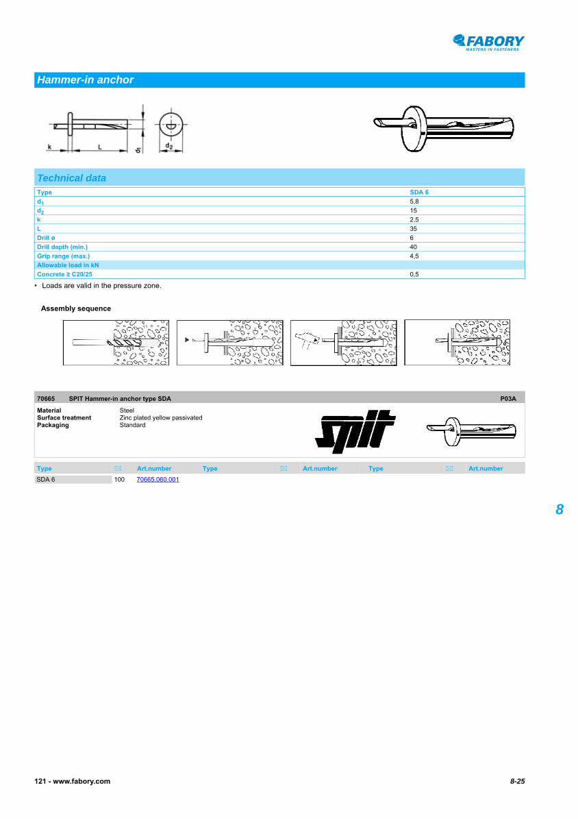
• Loads are valid in the pressure zone.
SPIT Hammer-in anchor type SDA70665
SPIT Hammer-in anchor type SDA
Hammer-in anchor
Technical dataType SDA 6
d1 5,8
d2 15
k 2,5
L 35
Drill ø 6
Drill depth (min.) 40
Grip range (max.) 4,5
Allowable load in kN
Concrete ≥ C20/25 0,5
70665 SPIT Hammer-in anchor type SDA P03A
Material Steel Surface treatment Zinc plated yellow passivatedPackaging Standard
Type Art.number Type Art.number Type Art.number
Assembly sequence
SDA 6 100 70665.060.001

8-26 121 - www.fabory.com
8
• A DACROMET® surface coating eliminates the possibilities of damage which can arise due to hydrogen embrittlement.• Drill depth (min.) For through fixing.• Concrete ≥ B25 Recommended load for non-cracked concrete.
FISCHER Nail sleeve type FNH63223
FISCHER Nail sleeve type FNH
Nail sleeve
Technical dataType FNH 5/50 FNH 6/40 FNH 6/50 FNH 6/60 FNH 6/80 FNH 8/70 FNH 8/90 FNH 8/110 FNH 8/130 FNH 8/150
d 5 6 6 6 6 8 8 8 8 8
L 50 40 50 60 80 70 90 110 130 150
Drill ø 5 6 6 6 6 8 8 8 8 8
Drill depth (min.) 30 40 40 40 40 50 50 50 50 50
Grip range (max.) 30 10 20 30 50 30 50 70 90 110
Allowable load in kN
Concrete ≥ C20/25 0,2 0,55 0,55 0,55 0,55 1,1 1,1 1,1 1,1 1,1
63223 FISCHER Nail sleeve type FNH N03A
Material Steel Surface treatment Dacromet 500 LC Grade APackaging Standard
Type Art.number Type Art.number Type Art.number
Assembly sequence
FNH 5/50 100 63223.050.050FNH 6/40 100 63223.060.040FNH 6/50 100 63223.060.050FNH 6/60 100 63223.060.060
FNH 6/80 100 63223.060.080FNH 8/70 100 63223.080.070FNH 8/90 50 63223.080.090FNH 8/110 50 63223.080.110
FNH 8/130 100 63223.080.130FNH 8/150 50 63223.080.150
8-27121 - www.fabory.com
8
MAXXFAST Wall plug HammerFast30510
MAXXFAST Wall plug HammerFast
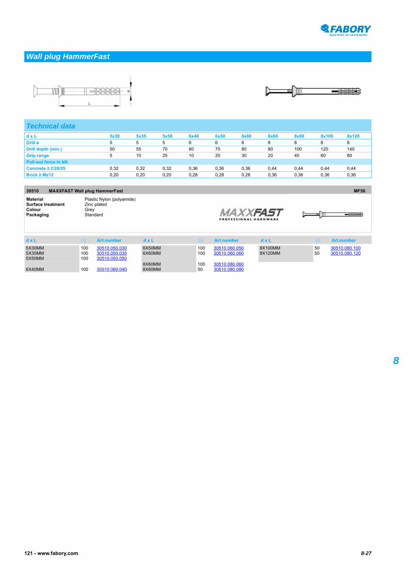
Wall plug HammerFast
Technical datad x L 5x30 5x35 5x50 6x40 6x50 6x60 8x60 8x80 8x100 8x120
Drill ø 5 5 5 6 6 6 8 8 8 8
Drill depth (min.) 50 55 70 60 70 80 80 100 120 140
Grip range 5 10 25 10 20 30 20 40 60 80
Pull-out force in kN
Concrete ≥ C20/25 0,32 0,32 0,32 0,36 0,36 0,36 0,44 0,44 0,44 0,44
Brick ≥ Mz12 0,20 0,20 0,20 0,28 0,28 0,28 0,36 0,36 0,36 0,36
30510 MAXXFAST Wall plug HammerFast MF50
Material Plastic Nylon (polyamide)Surface treatment Zinc platedColour GreyPackaging Standard
d x L Art.number d x L Art.number d x L Art.number
5X30MM 100 30510.050.0305X35MM 100 30510.050.0355X50MM 100 30510.050.050
6X40MM 100 30510.060.040
6X50MM 100 30510.060.0506X60MM 100 30510.060.060
8X60MM 100 30510.080.0608X80MM 50 30510.080.080
8X100MM 50 30510.080.1008X120MM 50 30510.080.120

8-28 121 - www.fabory.com
8
• With pre-assembledsteel zinc plated, yellow passivated nail or stainless steel A2 nail with Pozidriv (Z) cross recessed head.• It is advised to take a safetyfactor: ≥ 7.
FISCHER Hammerfix type N-Z63611
FISCHER Hammerfix type N-Z
Hammerfix type N-Z
Technical dataType N5x30 Z N5x40 Z N5x50 Z N6x40 Z N6x60 Z N6x80 Z N8x60 Z N8x80 Z N8x100 Z N8x120 Z N10x100 Z N10x135 Z N10x160 Z
d 5 5 5 6 6 6 8 8 8 8 10 10 10
L 30 40 50 40 60 80 60 80 100 120 100 135 160
Nail dimension 3,5x38 3,5x48 3,5x58 4x48 4x64 4x88 5x65 5x85 5x10⁵ 5x120 7x110 7x145 7x170
Drill ø 5 5 5 6 6 6 8 8 8 8 10 10 10
Drill depth (min.) 45 55 65 55 75 95 75 95 115 135 115 150 175
Grip range (max.) 5 15 25 10 30 50 20 40 60 80 50 85 110
Pull-out force in kN
Concrete C20/25 1,1 1,1 1,1 1,4 1,4 1,4 1,9 1,9 1,9 1,9 3,4 3,4 3,4
Brick Mz12 1 1 1 1,2 1,2 1,2 1,7 1,7 1,7 1,7 3 3 3
Pumice grit V4 0,2 0,2 0,2 0,8 0,8 0,8 0,9 0,9 0,9 0,9 1,1 1,1 1,1
Sandlime brick KS12 1 1 1 1,2 1,2 1,2 1,7 1,7 1,7 1,7 3 3 3
Cellular concrete G2 0,2 0,2 0,2 0,25 0,25 0,25 0,5 0,5 0,5 0,5 0,7 0,7 0,7
Cellular concrete G4 0,5 0,5 0,5 0,65 0,65 0,65 0,8 0,8 0,8 0,8 1,2 1,2 1,2
Assembly sequence
Article groupsMaterial Surface treatment Colour Packaging Code Page
Plastic Nylon Zipl Grey Standard 63611 8-28
Plastic Nylon Grey Standard 63616 8-29
63611 FISCHER Hammerfix type N-Z N03C
Material Plastic Nylon (polyamide)Surface treatment Zinc platedColour GreyPackaging Standard
Type Art.number Type Art.number Type Art.number
N 5X30MM 100 63611.050.030N 5X30 BR 100 63611.050.031N 5X40 BR 100 63611.050.040N5X40Z 100 63611.050.041N 5X50MM 100 63611.050.050N 5X40 WT 100 63611.050.411
N 5X50 WT 100 63611.050.511N 6X40MM 50 63611.060.040N 6X60MM 50 63611.060.060N 6X80MM 50 63611.060.080N 8X60MM 50 63611.080.060N 8X80MM 50 63611.080.080
N 8X100MM 50 63611.080.100N 8X120MM 50 63611.080.120N 10X100MM 50 63611.100.100N 10X135MM 50 63611.100.135N 10X160MM 50 63611.100.160

8-29121 - www.fabory.com
8
FISCHER Hammerfix type N-Z St.st. A263616
FISCHER Hammerfix type N-Z St.st. A2
63616 FISCHER Hammerfix type N-Z St.st. A2 N03C
Material Plastic Nylon (polyamide)Colour GreyPackaging Standard
Type Art.number Type Art.number Type Art.number
5X30MM 100 63616.050.0306X40MM 50 63616.060.040
6X60MM 50 63616.060.0608X60MM 50 63616.080.060
8X80MM 50 63616.080.0808X100MM 50 63616.080.100

8-30 121 - www.fabory.com
8 FISCHER Hammerfix type N-FZ63615
FISCHER Hammerfix type N-FZ
Hammerfix type N-FZ
Technical dataType N6x40 FZ N8x40 FZ
d 6 8
L 40 40
dk 13 20
Nail dimension 4x48 5x45
Drill ø 6 8
Drill depth (min.) 55 55
Grip range (max.) 7 0,5
Pull-out force in kN
Concrete C20/25 1,4 1,9
Brick Mz12 1,2 1,7
Pumice grit V4 0,8 0,9
Sandlime brick KS12 1,2 1,7
Cellular concrete G2 0,25 0,5
Cellular concrete G4 0,65 0,8
63615 FISCHER Hammerfix type N-FZ N03C
Material Plastic Nylon (polyamide)Colour GreyPackaging Standard
Type Art.number Type Art.number Type Art.number
Assembly sequence
N 6X40 FZ 50 63615.060.040N 8X40 FZ 50 63615.080.040

8-31121 - www.fabory.com
8
• Pull-out force in kN.• It is advised to take a safety factor ≥ 7.
FISCHER Hammerfix with isolating washer type N-D63617
FISCHER Hammerfix with isolating washer type N-D63617
• With pre-assembled stainless steel A2 nail with Pozidriv (Z) cross recess and with stainless steel A2/elastomer isolating washer.
Hammerfix with isolating washer
Technical dataType N6x40 D N6x60 D
d1 6 6
L 40 60
d2 19 19
Nail dimension 4x48 4x64
Drill ø 6 6
Drill depth (min.) 55 75
Grip range (max.) 10 30
Pull-out force in kN
Concrete C20/25 1,4 1,4
Brick Mz12 1,2 1,2
Pumice grit V4 0,8 0,8
Sandlime brick KS12 1,2 1,2
Cellular concrete G2 0,25 0,25
Cellular concrete G4 0,65 0,65
63617 FISCHER Hammerfix with isolating washer type N-D N03C
Material Plastic Nylon (polyamide)Colour GreyPackaging Standard
Type Art.number Type Art.number Type Art.number
6X40MM 50 63617.060.0406X60MM 50 63617.060.060
8-32 121 - www.fabory.com
8
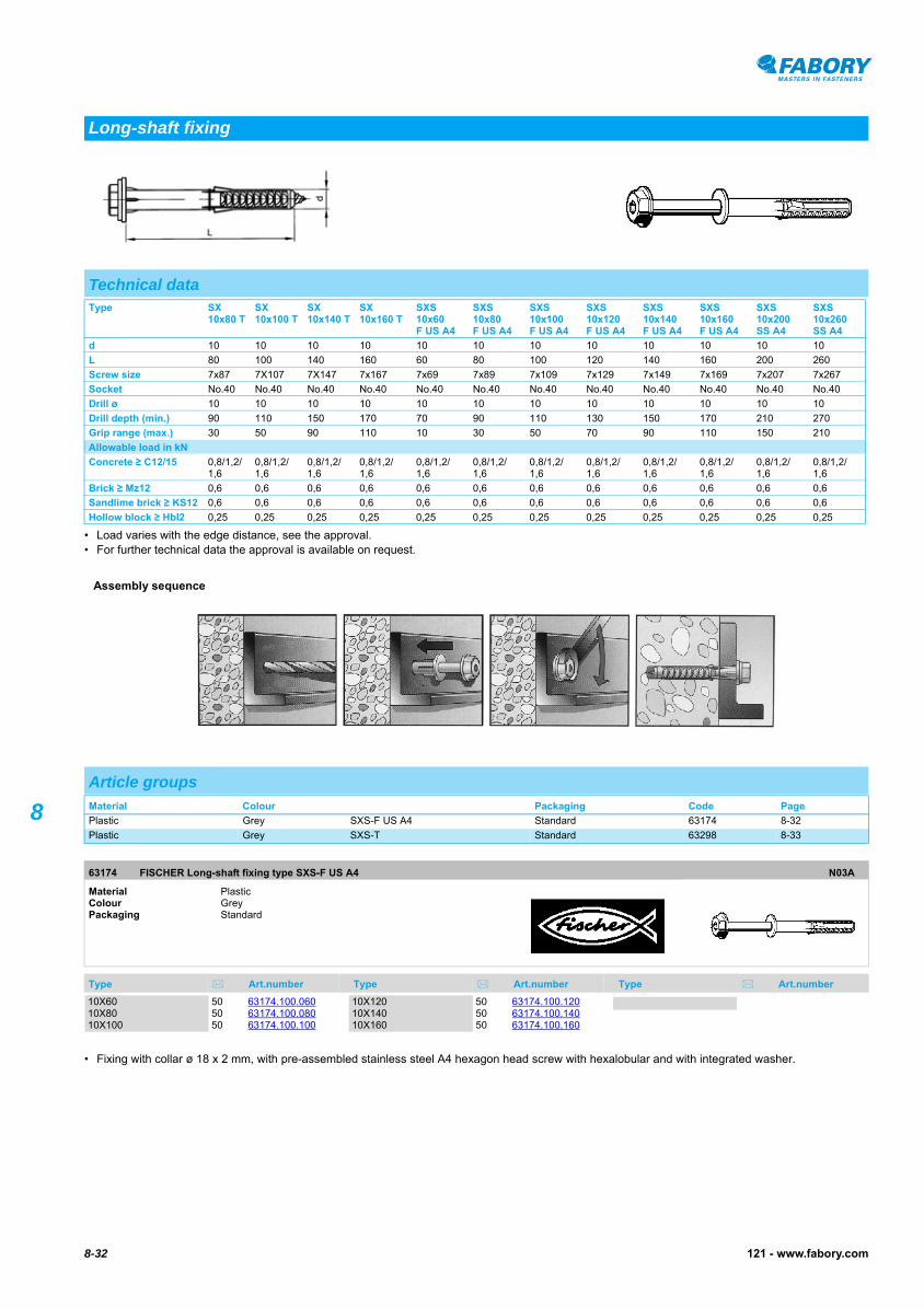
• Load varies with the edge distance, see the approval.• For further technical data the approval is available on request.
FISCHER Long-shaft fixing type SXS-F US A463174
• Fixing with collar ø 18 x 2 mm, with pre-assembled stainless steel A4 hexagon head screw with hexalobular and with integrated washer.FISCHER Long-shaft fixing type SXS-F US A4
Long-shaft fixing
Technical dataType SX
10x80 TSX 10x100 T
SX 10x140 T
SX 10x160 T
SXS 10x60F US A4
SXS 10x80 F US A4
SXS 10x100 F US A4
SXS 10x120 F US A4
SXS 10x140 F US A4
SXS 10x160 F US A4
SXS 10x200 SS A4
SXS 10x260 SS A4
d 10 10 10 10 10 10 10 10 10 10 10 10
L 80 100 140 160 60 80 100 120 140 160 200 260
Screw size 7x87 7X10⁷ 7X147 7x167 7x69 7x89 7x10⁹ 7x129 7x149 7x169 7x207 7x267
Socket No.40 No.40 No.40 No.40 No.40 No.40 No.40 No.40 No.40 No.40 No.40 No.40
Drill ø 10 10 10 10 10 10 10 10 10 10 10 10
Drill depth (min.) 90 110 150 170 70 90 110 130 150 170 210 270
Grip range (max.) 30 50 90 110 10 30 50 70 90 110 150 210
Allowable load in kN
Concrete ≥ C12/15 0,8/1,2/1,6
0,8/1,2/1,6
0,8/1,2/1,6
0,8/1,2/1,6
0,8/1,2/1,6
0,8/1,2/1,6
0,8/1,2/1,6
0,8/1,2/1,6
0,8/1,2/1,6
0,8/1,2/1,6
0,8/1,2/1,6
0,8/1,2/1,6
Brick ≥ Mz12 0,6 0,6 0,6 0,6 0,6 0,6 0,6 0,6 0,6 0,6 0,6 0,6
Sandlime brick ≥ KS12 0,6 0,6 0,6 0,6 0,6 0,6 0,6 0,6 0,6 0,6 0,6 0,6
Hollow block ≥ Hbl2 0,25 0,25 0,25 0,25 0,25 0,25 0,25 0,25 0,25 0,25 0,25 0,25
Assembly sequence
Article groupsMaterial Colour Packaging Code Page
Plastic Grey SXS-F US A4 Standard 63174 8-32
Plastic Grey SXS-T Standard 63298 8-33
63174 FISCHER Long-shaft fixing type SXS-F US A4 N03A
Material Plastic Colour GreyPackaging Standard
Type Art.number Type Art.number Type Art.number
10X60 50 63174.100.06010X80 50 63174.100.08010X100 50 63174.100.100
10X120 50 63174.100.12010X140 50 63174.100.14010X160 50 63174.100.160

8-33121 - www.fabory.com
8
FISCHER Long-shaft fixing type SXS-T63298
• With pre-assembled steel zinc plated countersunk head screw with hexalobular.
63298 FISCHER Long-shaft fixing type SXS-T N03A
Material Plastic Colour GreyPackaging Standard
Type Art.number Type Art.number Type Art.number
Assembly sequence
SXS 10X80T 50 63298.100.080SXS 10X100T 50 63298.100.100
SXS 10X140T 50 63298.100.140 SXS 10X160T 50 63298.100.160

8-34 121 - www.fabory.com
8
• do = Nominal diameter of drill bit• Min. td = Recommended drilling depth• hef = Effective anchorage depth• tfix = Grip range
FISCHER Frame fixing type F-S63191
FISCHER Frame fixing type F-S
Frame fixing type F-S
Technical dataType F 10 S 75 F 10 S 100 F 10 S 120 F 10 S 140 F 10 S 165
do 10 10 10 10 10
L 75 100 120 140 165
Min. td 90 115 135 155 180
hef 50 50 50 50 50
tfix 15 40 60 80 105
63191 FISCHER Frame fixing type F-S N03A
Material Plastic Nylon (polyamide)Colour GreyPackaging Standard
Type Art.number Type Art.number Type Art.number
Assembly sequence
F 10 S 75 50 63191.100.075F 10 S 100 50 63191.100.100
F 10 S 120 50 63191.100.120F 10 S 140 50 63191.100.140
F 10 S 165 50 63191.100.165
8-35121 - www.fabory.com
8
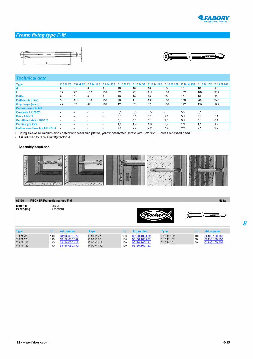
• Fixing sleeve aluminium-zinc coated with steel zinc plated, yellow passivated screw with Pozidriv (Z) cross recessed head.• It is advised to take a safety factor: 4.
FISCHER Frame fixing type F-M63190
FISCHER Frame fixing type F-M
Frame fixing type F-M
Technical dataType F 8 M 72 F 8 M 92 F 8 M 112 F 8 M 132 F 10 M 72 F 10 M 92 F 10 M 112 F 10 M 132 F 10 M 152 F 10 M 182 F 10 M 202
d 8 8 8 8 10 10 10 10 10 10 10
L 72 92 112 132 72 92 112 132 152 182 202
Drill ø 8 8 8 8 10 10 10 10 10 10 10
Drill depth (min.) 90 110 130 150 90 110 130 150 170 200 220
Grip range (max.) 42 62 82 102 42 62 82 102 122 152 172
Pull-out force in kN
Concrete ≥ C20/25 - - - - 5,5 5,5 5,5 - 5,5 5,5 5,5
Brick ≥ Mz12 - - - - 5,1 5,1 5,1 5,1 5,1 5,1 5,1
Sandlime brick ≥ KSV12 - - - - 5,1 5,1 5,1 5,1 5,1 5,1 5,1
Pumice grit ≥V2 - - - - 1,9 1,9 1,9 1,9 1,9 1,9 1,9
Hollow sandlime brick ≥ KSL6 - - - - 2,2 2,2 2,2 2,2 2,2 2,2 2,2
63190 FISCHER Frame fixing type F-M N03A
Material Steel Packaging Standard
Type Art.number Type Art.number Type Art.number
Assembly sequence
F 8 M 72 100 63190.080.072F 8 M 92 100 63190.080.092F 8 M 112 100 63190.080.112F 8 M 132 100 63190.080.132
F 10 M 72 100 63190.100.072F 10 M 92 100 63190.100.092F 10 M 112 100 63190.100.112F 10 M 132 100 63190.100.132
F 10 M 152 100 63190.100.152F 10 M 182 50 63190.100.182F 10 M 202 50 63190.100.202

8-36 121 - www.fabory.com
8
• do = Nominal diameter of drill bit• Min. td = Recommended drilling depth• hef = Effective anchorage depth• tfix = Grip range
FISCHER Frame fixing type FUR-T63195
FISCHER Frame fixing type FUR-T
Frame fixing type FUR-T
Technical datado x L Min. td hef tfix Socket
8x100 110 70 30 T30
8x120 130 70 50 T30
10x100 110 70 30 T40
10x115 125 70 45 T40
10x135 145 70 65 T40
63195 FISCHER Frame fixing type FUR-T N03A
Material Plastic Nylon (polyamide)Colour GreyPackaging Standard
Drill ø x L Art.number Drill ø x L Art.number Drill ø x L Art.number
Assembly sequence
8X100MM 50 63195.080.1008X120MM 50 63195.080.120
10X100MM 50 63195.100.10010X115MM 50 63195.100.115
10X135MM 50 63195.100.135

8-37121 - www.fabory.com
8
• do = Nominal diameter of drill bit• Min. td = Recommended drilling depth• hef = Effective anchorage depth• tfix = Grip range
FISCHER Frame fixing type FUR-SS63196
FISCHER Frame fixing type FUR-SS
Frame fixing type FUR-SS
Technical datado x L Min. td hef tfix8x80 90 70 10
8x100 110 70 30
8x120 130 70 50
10x80 90 70 10
10x100 110 70 30
10x115 125 70 45
10x135 145 70 65
10x160 170 70 90
do x L Min. td hef tfix10x185 195 70 115
10x200 210 70 130
10x230 240 70 160
do x L Min. td hef tfix
63196 FISCHER Frame fixing type FUR-SS N03A
Material Plastic Nylon (polyamide)Colour GreyPackaging Standard
Drill ø x L Art.number Drill ø x L Art.number Drill ø x L Art.number
Assembly sequence
8X80MM 50 63196.080.0808X100MM 50 63196.080.1008X120MM 50 63196.080.12010X80MM 50 63196.100.080
10X100MM 50 63196.100.10010X115MM 50 63196.100.11510X135MM 50 63196.100.13510X160MM 50 63196.100.160
10X185MM 50 63196.100.18510X200MM 50 63196.100.20010X230MM 50 63196.100.230

8-38 121 - www.fabory.com
8
• do = Nominal diameter of drill bit.• Min. td = Recommended drilling depth.• hef = Effective anchorage depth.• tfix = Grip range.
FISCHER Frame fixing type SXR-T63192
FISCHER Frame fixing type SXR-T
Frame fixing type SXR-T
Technical datado x L Min. td hef tfix Socket
80x60 70 50 10 T30
80x80 90 50 30 T30
80x100 110 50 50 T30
80x120 130 50 70 T30
10x80 90 50 30 No.40
10x100 110 50 50 No.40
10x120 130 50 70 No.40
10x140 150 50 90 No.40
10x160 170 50 110 No.40
63192 FISCHER Frame fixing type SXR-T N03A
Material Plastic Nylon (polyamide)Colour GreyPackaging Standard
Drill ø x L Art.number Drill ø x L Art.number Drill ø x L Art.number
Assembly sequence
8X60 T 50 63192.080.0608X80 T 50 63192.080.080SXR 8X100 T 50 63192.080.100
SXR 8X120 T 50 63192.080.12010X80 T 50 63192.100.08010X100 T 50 63192.100.100
10X120 T 50 63192.100.12010X140 T 50 63192.100.14010X160 T 50 63192.100.160

8-39121 - www.fabory.com
8
• Suitable for concrete, solid brick, sand lime solid bricks, perforated bricks, sand lime perforated bricks, hollow blocks, solid pumice, aircrete, natural stone etc.
FISCHER Window frame screw type FFSZ - Head 7,5/TX 2563560
FISCHER Window frame screw type FFSZ - Head 7,5/TX 2563560
FISCHER Window frame screw type FFS - Head 11,5/TX 3063562
FISCHER Window frame screw type FFS - Head 11,5/TX 30
Window frame screw
Technical dataType d L Drill ø
7,5x72 7,5 72 6
7,5x92 7,5 92 6
7,5x112 7,5 112 6
7,5X132 7,5 132 6
7,5X152 7,5 152 6
7,5X182 7,5 182 6
7,5X212 7,5 212 6
Assembly sequence
Article groupsMaterial Surface treatment Packaging Code Page
St Zipl FFSZ Standard 63560 8-39
St Zipl FFS Standard 63562 8-39
63560 FISCHER Window frame screw type FFSZ - Head 7,5/TX 25 N03A
Material Steel Surface treatment Zinc platedPackaging Standard
Type Art.number Type Art.number Type Art.number
FFSZ 7,5X72 100 63560.075.072FFSZ 7,5X92 100 63560.075.092
FFSZ 7,5X112 100 63560.075.112FFSZ 7,5X132 100 63560.075.132
FFSZ 7,5X212 100 63560.075.212
63562 FISCHER Window frame screw type FFS - Head 11,5/TX 30 N03A
Material Steel Surface treatment Zinc platedPackaging Standard
Type Art.number Type Art.number Type Art.number
FFS 7,5X72 100 63562.075.072FFS 7,5X92 100 63562.075.092FFS 7,5X112 100 63562.075.112
FFS 7,5X132 100 63562.075.132FFS 7,5X152 100 63562.075.152FFS 7,5X182 100 63562.075.182
FFS 7,5X212 100 63562.075.212

8-40 121 - www.fabory.com
8
FISCHER Adjustable screw type JS63601
FISCHER Adjustable screw type JS
Adjustable screw
Technical dataType JS 6x110
Socket No.40
Drill ø 5
Drill depth (min.) 50-110
Assembly depth (min.) 30
Stepless adjustment 0-55
Wood thickness (max.) 25
63601 FISCHER Adjustable screw type JS N03B
Material Steel Surface treatment Zinc platedPackaging Standard
Type Art.number Type Art.number Type Art.number
Assembly sequence
JS 6X110MM 50 63601.060.110

8-41121 - www.fabory.com
8
• Adjustable fixing type S10J75S for assembly for wood on stone.• With adjustable screw type JS 6 x 110, steel zinc plated, yellow passivated.
FISCHER Adjustable fixing type S10J75S63600
FISCHER Adjustable fixing type S10J75S
Adjustable fixing
Technical dataType S10J75S
Plug length 75
Socket No.40
Drill ø 10
Drill depth (min.) 115
Assembly depth (min.) 50
Stepless adjustment 0-30
Wood thickness (max.) 25
63600 FISCHER Adjustable fixing type S10J75S N03A
Material Plastic Nylon (polyamide)Colour GreyPackaging Standard
Type Art.number Type Art.number Type Art.number
Assembly sequence
S 10-J 75 S 50 63600.060.110

8-42 121 - www.fabory.com
8
FISCHER Cover cap for window frame screws type FSS A63590
FISCHER Cover cap for window frame screws type FSS A
Cover cap for window frame screws
Technical dataType FSS A-W FSS A-BR
d 14 14
h 4 4
63590 FISCHER Cover cap for window frame screws type FSS A N03A
Material Plastic Polyamide (nylon)Class 6Packaging Standard
Type Art.number Type Art.number Type Art.number
WHITE 100 63590.000.011DARK BROWN 100 63590.000.019

8-43121 - www.fabory.com
8
• Drilling depth = fixing part + coating layer + length of plug + 10 mm.• Length of screw = fixing part + coating layer + length of plug.• It is advised to take a safetyfactor.
Expanding plug09610
Expanding plug
Expanding plug
Technical datad1 M4 M5 M6 M8 M10 M12
P 0,7 0,8 1 1,25 1,5 1,75
d2 5 6 7,5 10 12 15,5
m 16 20 24 30 34 40
Drill ø 5,5 6,5 8 11 13 18
Pull-out force in kN
Concrete ≥ C20/25 0,25 0,4 0,65 1,1 1,6 2,2
Stone ≥ 15 N/mm2 (Mz/KS/HSV) 0,2 3,35 0,55 0,9 1,3 1,6
09610 Expanding plug N07A
Thread Metric threadMaterial Brass Packaging Standard
d1 x m Art.number d1 x m Art.number d1 x m Art.number
Special features of expanding plugs: - provided with a conical inner side, expanding equally against the wall of the hole during tightening - application for installation through the fixture hole - they can be applied in concrete, stone, bricks, tiles and massive wood - resistant against corrosion - resistant against temperatures up to 200°C
M4X16 50 09610.040.016M5X20 50 09610.050.020
M6X24 50 09610.060.024M8X30 25 09610.080.030
M10X34 25 09610.100.034M12X40 25 09610.120.040

8-44 121 - www.fabory.com
8
• Pull-out force in kN.• It is advised to take a safety factor ≥ 7.
FISCHER Expansion anchor with brass cone type M63400
FISCHER Expansion anchor with brass cone type M
Expansion anchor with brass cone
Technical dataType M5 M6 M8 M10 M12 M16
d 10 12 16 20 24 32
L 35 40 50 60 70 90
Drill ø 10 12 16 20 24 32
Drill depth (min.) 45 50 65 80 90 120
Pull-out force in kN -
Concrete ≥ C20/25 5,5 9 13 22 25 43
63400 FISCHER Expansion anchor with brass cone type M N03B
Thread Metric threadMaterial Glass-fibre reinforced plastic Packaging Standard
Type Art.number Type Art.number Type Art.number
Assembly sequence
M5 50 63400.050.001M6 50 63400.060.001
M8 20 63400.080.001M10 10 63400.100.001
M12 5 63400.120.001

8-45121 - www.fabory.com
8
• Length of screw min. = length of plug + thickness of fixing part.• It is advised to take a safety factor: ≥ 4.
FISCHER Anchor type PA63410
FISCHER Anchor type PA
Anchor
Technical dataType PA 4 M6/7,5 PA 4 M6/13,5 PA 4 M8/25 PA 4 M10/25
d M6 M6 M8 M10
P 1 1 1,25 1,5
L 7,5 13,5 25 25
Drill ø 8 8 10 12
Drill depth (min.) 7,5 13,5 25 25
Drill ø in construction 7,5 7,5 9,5 11,5
Assembly depth (min.) 7,5 13,5 25 25
Pull-out force in kN
Chipboard 0,8 1,6 - -
Pine wood 0,7 1,5 - -
Beech wood 2 4 - -
Plastic 3 8 - -
Brick Mz12 - 3,2 7,8 9,2
63410 FISCHER Anchor type PA N03A
Thread Metric threadMaterial Brass Packaging Standard
Type Art.number Type Art.number Type Art.number
Assembly sequence
PA4 M6X7,5 200 63410.060.007PA4 M6X13,5 100 63410.060.013
PA4 M8X25 50 63410.080.025PA4 M10X25 25 63410.100.025
8-46 121 - www.fabory.com
8
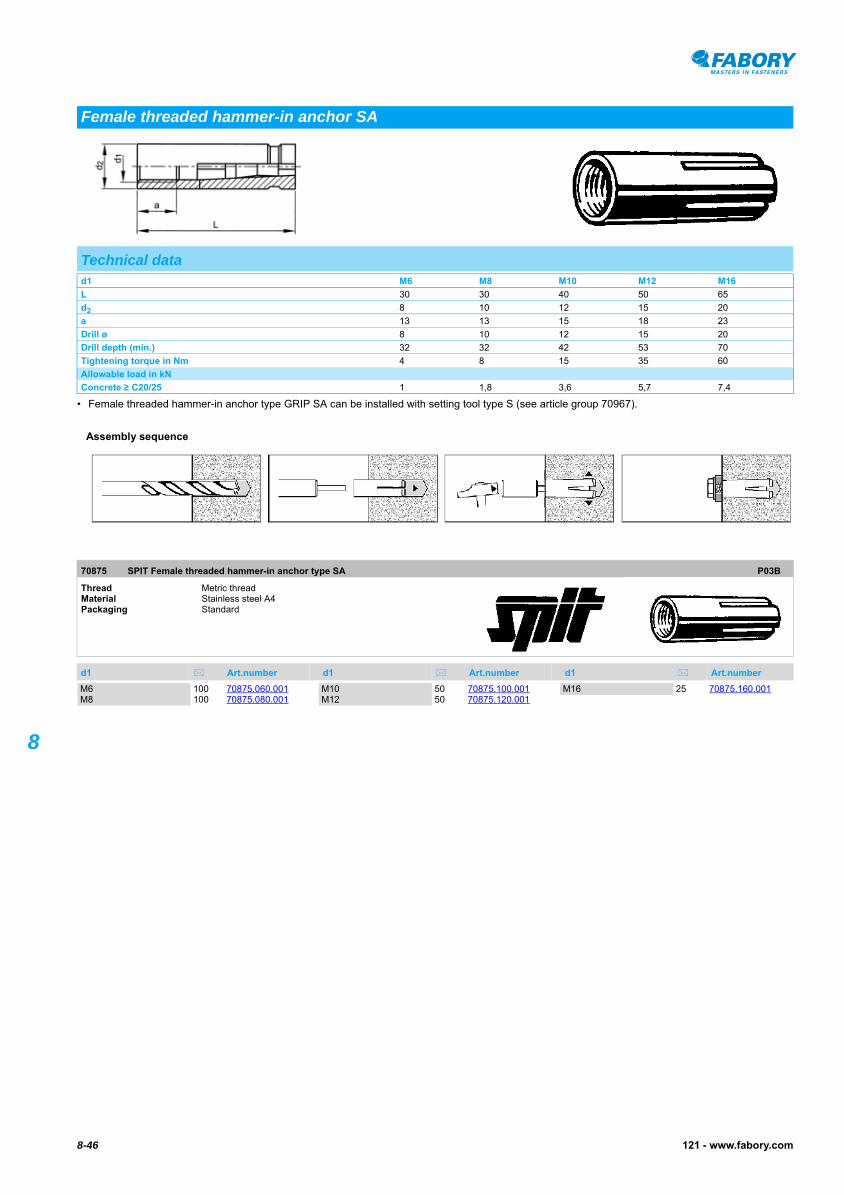
• Female threaded hammer-in anchor type GRIP SA can be installed with setting tool type S (see article group 70967).
SPIT Female threaded hammer-in anchor type SA70875
SPIT Female threaded hammer-in anchor type SA
Female threaded hammer-in anchor SA
Technical datad1 M6 M8 M10 M12 M16
L 30 30 40 50 65
d2 8 10 12 15 20
a 13 13 15 18 23
Drill ø 8 10 12 15 20
Drill depth (min.) 32 32 42 53 70
Tightening torque in Nm 4 8 15 35 60
Allowable load in kN
Concrete ≥ C20/25 1 1,8 3,6 5,7 7,4
70875 SPIT Female threaded hammer-in anchor type SA P03B
Thread Metric threadMaterial Stainless steel A4Packaging Standard
d1 Art.number d1 Art.number d1 Art.number
Assembly sequence
M6 100 70875.060.001M8 100 70875.080.001
M10 50 70875.100.001M12 50 70875.120.001
M16 25 70875.160.001

8-47121 - www.fabory.com
8
SPIT Setting tool70967
SPIT Setting tool
Setting tool SA
70967 SPIT Setting tool P03C
Material Steel Packaging Standard
Type Art.number Type Art.number Type Art.number
S 6 1 70967.000.006S 8 1 70967.000.008
S 10 1 70967.000.010S 12 1 70967.000.012
8-48 121 - www.fabory.com
8
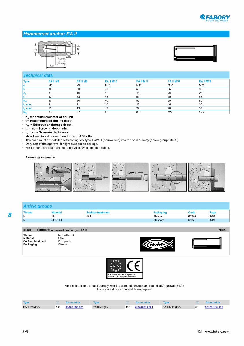
• do = Nominal diameter of drill bit.• t = Recommended drilling depth.• hef = Effective anchorage depth.• ls min. = Screw-in depth min.• ls max. = Screw-in depth max.• kN = Load in kN in combination with 8.8 bolts.• The cone must be installed with setting tool type EAW H (narrow end) into the anchor body (article group 63322).• Only part of the approval for light suspended ceilings.• For further technical data the approval is available on request.
Hammerset anchor EA II
Technical dataType EA II M6 EA II M8 EA II M10 EA II M12 EA II M16 EA II M20
d M6 M8 M10 M12 M16 M20
L 30 30 40 50 65 80
do 8 10 12 15 20 25
t 32 33 43 54 70 85
hef 30 30 40 50 65 80
ls min. 6 8 10 12 16 20
ls max. 13 13 17 22 28 34
kN 3,9 3,9 6,1 8,5 12,6 17,2
Assembly sequence
Article groupsThread Material Surface treatment Packaging Code Page
M St Zipl Standard 63320 8-48
M St.St. A4 Standard 63321 8-49
63320 FISCHER Hammerset anchor type EA II N03A
Thread Metric threadMaterial Steel Surface treatment Zinc platedPackaging Standard
Type Art.number Type Art.number Type Art.number
Final calculations should comply with the complete European Technical Approval (ETA), this approval is also available on request.
EA II M6 (EV) 100 63320.060.001 EA II M8 (EV) 100 63320.080.001 EA II M10 (EV) 50 63320.100.001

63320 FISCHER Hammerset anchor type EA II Type Art.number Type Art.number Type Art.number
8-49121 - www.fabory.com
8
FISCHER Hammerset anchor type EA II63320
FISCHER Hammerset anchor type EA II
EA II M12 (EV) 25 63320.120.001EA II M12 D (EV) 25 63320.120.005
EA II M16 (EV) 20 63320.160.001EA II M20 (EV) 10 63320.200.001
63321 FISCHER Hammerset anchor type EA II N03A
Thread Metric threadMaterial Stainless steel A4Packaging Standard
Type Art.number Type Art.number Type Art.number
Final calculations should comply with the complete European Technical Approval (ETA), this approval is also available on request.
EA II M6 A4 100 63321.060.001EA II M8 A4 100 63321.080.001
EA II M10 A4 50 63321.100.001EA II M12 A4 25 63321.120.001
EA II M16 A4 20 63321.160.001

8-50 121 - www.fabory.com
8
Setting tool for EA II63322
Setting tool for EA II
Setting tool for EA II
63322 Setting tool for EA II N03A
Material Steel Surface treatment Zinc platedPackaging Standard
Type Art.number Type Art.number Type Art.number
EAW H 6 PLUS 1 63322.060.001EAW H 8 PLUS 1 63322.080.001
EAW H 10 PLUS 1 63322.100.001EAW H 12 PLUS 1 63322.120.001
EAW H 16 PLUS 1 63322.160.001EAW H 20 PLUS 1 63322.200.001
8-51121 - www.fabory.com
8
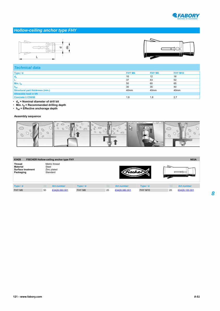
• do = Nominal diameter of drill bit• Min. td = Recommended drilling depth• hef = Effective anchorage depth
FISCHER Hollow-ceiling anchor type FHY63428
FISCHER Hollow-ceiling anchor type FHY
Hollow-ceiling anchor type FHY
Technical dataType / d FHY M6 FHY M8 FHY M10
do 10 12 16
L 37 43 52
Min. td 50 60 65
hef 30 35 40
Structural part thickness (min.) 40mm 40mm 40mm
Allowable load in kN
Concrete ≥ C50/60 1,8 1,8 2,7
63428 FISCHER Hollow-ceiling anchor type FHY N03A
Thread Metric threadMaterial Steel Surface treatment Zinc platedPackaging Standard
Type / d Art.number Type / d Art.number Type / d Art.number
Assembly sequence
FHY M6 50 63428.060.001 FHY M8 25 63428.080.001 FHY M10 20 63428.100.001

8-52 121 - www.fabory.com
8
• do = Nominal diameter of drill bit• tfix = Grip range• hef = Effective anchorage depth• Min. td = Recommended drilling depth• The allowable load is valid for one single anchor, at cracked concrete (tensile zone) with concrete class ≥ C20/25.
FISCHER Sleeve anchor FSA-S63226
FISCHER Sleeve anchor FSA-S
Sleeve anchor FSA-S
Technical dataType FSA 8/15 S FSA 8/40 S FSA 8/65 S FSA 10/10 S FSA 10/35 S FSA 10/60 S FSA 12/10 S FSA 12/25 S FSA 12/50 S
do 8 8 8 10 10 10 12 12 12
L 59 84 109 60 86 110 70 85 110
tfix 15 40 65 10 35 60 10 25 50
hef 35 35 35 40 40 40 50 50 50
Min. td 65 90 115 65 90 115 75 90 115
Allowable load in kN
Concrete ≥ C20/25 5,2 5,2 5,2 12,9 12,9 12,9 25,7 25,7 25,7
63226 FISCHER Sleeve anchor FSA-S N03A
Thread Metric threadMaterial Steel Surface treatment Zinc platedPackaging Standard
Type Art.number Type Art.number Type Art.number
Assembly sequence
FSA 8/15 S 50 63226.080.015FSA 8/40 S 50 63226.080.040FSA 8/65 S 50 63226.080.065
FSA 10/10 S 20 63226.100.010FSA 10/35 S 20 63226.100.035FSA 10/60 S 20 63226.100.060
FSA 12/10 S 20 63226.120.010FSA 12/25 S 20 63226.120.025FSA 12/50 S 20 63226.120.050

8-53121 - www.fabory.com
8
• do = Nominal diameter of drill bit.• dd = Embedment depth.• df = Anchor diameter.• kN = Load in kN.
Expansion shield SA09015
Expansion shield SA09015
Expansion shield09560
Expansion shield
Expansion shield
NEN ≈2316
Technical dataType d L do dd df kN
SA06 M6 45 12 60 50 2,3
SA08 M8 50 14 65 50 3,7
SA10 M10 60 16 75 50 5,0
SA12 M12 75 20 70 25 6,7
SA16 M16 115 25 150 10 10,0
M6 (rvs) M6 40 12 60 50 -
M8 (rvs) M8 50 14 65 50 -
M10 (rvs) M10 60 16 75 50 -
M12 (rvs) M12 80 20 70 25 -
Article groupsThread Material Surface treatment Packaging Code Page
M St Zipl Standard 09015 8-53
M St.St. A4 Standard 09560 8-53
09015 Expansion shield SA P01A
Thread Metric threadMaterial Steel Surface treatment Zinc platedPackaging Standard
d x L Art.number d x L Art.number d x L Art.number
M6X45 (SA) 50 09015.060.045M8X50 (SA) 50 09015.080.050
M10X60 (SA) 50 09015.100.060M12X75 (SA) 25 09015.120.075
M16X115 (SA) 10 09015.160.115
09560 Expansion shield P01A
Thread Metric threadMaterial Stainless steel A4Packaging Standard
d1 x L Art.number d1 x L Art.number d1 x L Art.number
M6X40 50 09560.060.040M8X50 50 09560.080.050
M10X60 25 09560.100.060M12X80 10 09560.120.080
8-54 121 - www.fabory.com
8
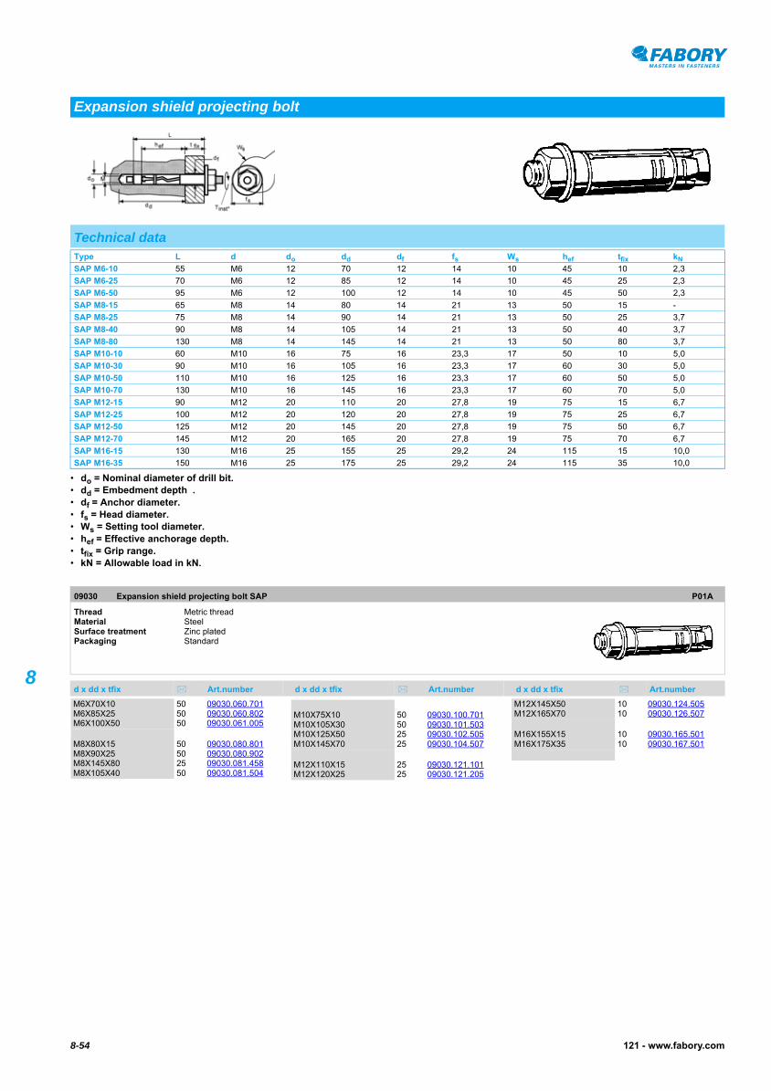
• do = Nominal diameter of drill bit.• dd = Embedment depth .• df = Anchor diameter.• fs = Head diameter.• Ws = Setting tool diameter.• hef = Effective anchorage depth.• tfix = Grip range.• kN = Allowable load in kN.
Expansion shield projecting bolt SAP09030
Expansion shield projecting bolt SAP
Expansion shield projecting bolt
Technical dataType L d do dd df fs Ws hef tfix kN
SAP M6-10 55 M6 12 70 12 14 10 45 10 2,3
SAP M6-25 70 M6 12 85 12 14 10 45 25 2,3
SAP M6-50 95 M6 12 100 12 14 10 45 50 2,3
SAP M8-15 65 M8 14 80 14 21 13 50 15 -
SAP M8-25 75 M8 14 90 14 21 13 50 25 3,7
SAP M8-40 90 M8 14 105 14 21 13 50 40 3,7
SAP M8-80 130 M8 14 145 14 21 13 50 80 3,7
SAP M10-10 60 M10 16 75 16 23,3 17 50 10 5,0
SAP M10-30 90 M10 16 105 16 23,3 17 60 30 5,0
SAP M10-50 110 M10 16 125 16 23,3 17 60 50 5,0
SAP M10-70 130 M10 16 145 16 23,3 17 60 70 5,0
SAP M12-15 90 M12 20 110 20 27,8 19 75 15 6,7
SAP M12-25 100 M12 20 120 20 27,8 19 75 25 6,7
SAP M12-50 125 M12 20 145 20 27,8 19 75 50 6,7
SAP M12-70 145 M12 20 165 20 27,8 19 75 70 6,7
SAP M16-15 130 M16 25 155 25 29,2 24 115 15 10,0
SAP M16-35 150 M16 25 175 25 29,2 24 115 35 10,0
09030 Expansion shield projecting bolt SAP P01A
Thread Metric threadMaterial Steel Surface treatment Zinc platedPackaging Standard
d x dd x tfix Art.number d x dd x tfix Art.number d x dd x tfix Art.number
M6X70X10 50 09030.060.701M6X85X25 50 09030.060.802M6X100X50 50 09030.061.005
M8X80X15 50 09030.080.801M8X90X25 50 09030.080.902M8X145X80 25 09030.081.458M8X105X40 50 09030.081.504
M10X75X10 50 09030.100.701M10X105X30 50 09030.101.503M10X125X50 25 09030.102.505M10X145X70 25 09030.104.507
M12X110X15 25 09030.121.101M12X120X25 25 09030.121.205
M12X145X50 10 09030.124.505M12X165X70 10 09030.126.507
M16X155X15 10 09030.165.501M16X175X35 10 09030.167.501

8-55121 - www.fabory.com
8
• do = Nominal diameter of drill bit.• dd = Embedment depth .• df = Anchor diameter.• fs = Head diameter.• Ws = Setting tool diameter.• hef = Effective anchorage depth.• tfix = Grip range.• kN = Allowable load in kN.
Expansion shield with hexagon head screw SAL09420
Expansion shield with hexagon head screw SAL
Expansion shield with hexagon head screw
Technical dataType L d do dd df fs Ws hef tfix kN
SAL M6-10 55 M6 12 70 13 14 10 45 10 2,3
SAL M6-25 70 M6 12 85 13 14 10 45 25 2,3
SAL M6-40 85 M6 12 100 13 14 10 45 40 2,3
SAL M8-10 60 M8 14 80 15 21 13 50 10 3,7
SAL M8-25 75 M8 14 90 15 21 13 50 25 3,7
SAL M8-40 90 M8 14 105 15 21 13 50 40 3,7
SAL M10-10 60 M10 16 75 18 24,1 17 50 10 5,0
SAL M10-25 85 M10 16 100 18 24,1 17 60 25 5,0
SAL M10-50 110 M10 16 125 18 24,1 17 60 50 5,0
SAL M10-75 135 M10 16 150 18 24,1 17 60 75 5,0
SAL M12-10 85 M12 20 105 22 29,2 19 75 10 6,7
SAL M12-25 90 M12 20 110 22 29,2 19 75 15 6,7
SAL M12-40 115 M12 20 135 22 29,2 19 75 40 6,7
SAL M12-60 135 M12 20 155 22 29,2 19 75 60 6,7
SAL M16-15 130 M16 25 155 27 29,2 24 115 15 10,0
SAL M16-30 145 M16 25 170 27 29,2 24 115 30 10,0
SAL M16-60 175 M16 25 200 27 29,2 24 115 60 10,0
09420 Expansion shield with hexagon head screw SAL P01A
Thread Metric threadMaterial Steel Surface treatment Zinc platedPackaging Standard
d x dd x tfix Art.number d x dd x tfix Art.number d x dd x tfix Art.number
M6X70X10 50 09420.060.701M6X85X25 50 09420.060.802M6X100X40 50 09420.061.004
M8X80X10 50 09420.080.801M8X90X25 50 09420.080.902M8X105X40 50 09420.081.504
M10X75X10 50 09420.100.701M10X100X25 50 09420.101.002M10X125X50 50 09420.102.505M10X150X75 25 09420.105.007M12X105X10 25 09420.120.501
M12X110X15 25 09420.121.101M12X135X40 25 09420.123.504
M12X155X60 25 09420.125.506
M16X170X30 10 09420.161.703M16X200X60 10 09420.162.006M16X155X15 10 09420.165.501
8-56 121 - www.fabory.com
8
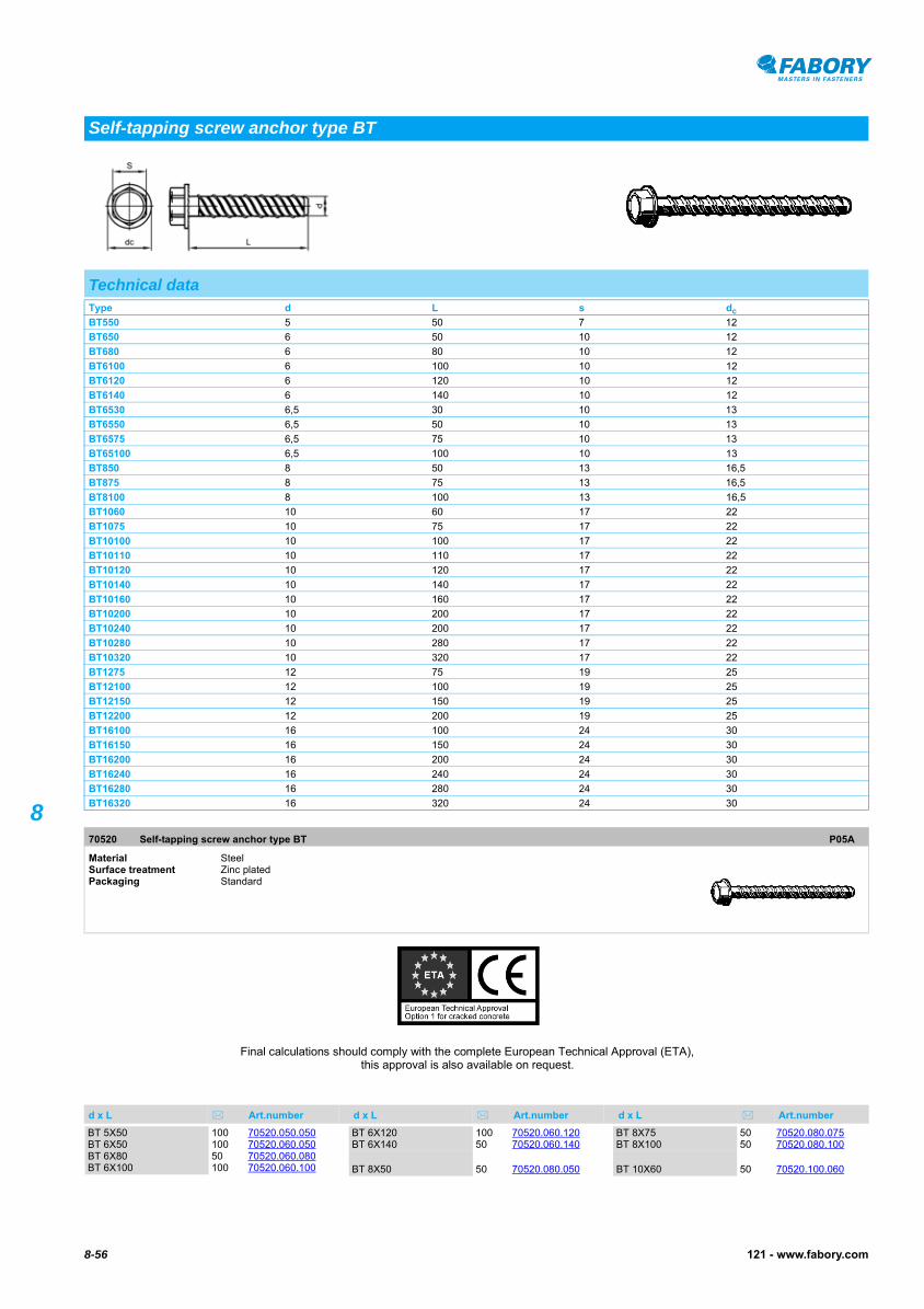
Self-tapping screw anchor type BT
Technical dataType d L s dc
BT550 5 50 7 12
BT650 6 50 10 12
BT680 6 80 10 12
BT6100 6 100 10 12
BT6120 6 120 10 12
BT6140 6 140 10 12
BT6530 6,5 30 10 13
BT6550 6,5 50 10 13
BT6575 6,5 75 10 13
BT65100 6,5 100 10 13
BT850 8 50 13 16,5
BT875 8 75 13 16,5
BT8100 8 100 13 16,5
BT1060 10 60 17 22
BT1075 10 75 17 22
BT10100 10 100 17 22
BT10110 10 110 17 22
BT10120 10 120 17 22
BT10140 10 140 17 22
BT10160 10 160 17 22
BT10200 10 200 17 22
BT10240 10 200 17 22
BT10280 10 280 17 22
BT10320 10 320 17 22
BT1275 12 75 19 25
BT12100 12 100 19 25
BT12150 12 150 19 25
BT12200 12 200 19 25
BT16100 16 100 24 30
BT16150 16 150 24 30
BT16200 16 200 24 30
BT16240 16 240 24 30
BT16280 16 280 24 30
BT16320 16 320 24 30
70520 Self-tapping screw anchor type BT P05A
Material Steel Surface treatment Zinc platedPackaging Standard
d x L Art.number d x L Art.number d x L Art.number
Final calculations should comply with the complete European Technical Approval (ETA), this approval is also available on request.
BT 5X50 100 70520.050.050BT 6X50 100 70520.060.050BT 6X80 50 70520.060.080BT 6X100 100 70520.060.100
BT 6X120 100 70520.060.120BT 6X140 50 70520.060.140
BT 8X50 50 70520.080.050
BT 8X75 50 70520.080.075BT 8X100 50 70520.080.100
BT 10X60 50 70520.100.060

70520 Self-tapping screw anchor type BT d x L Art.number d x L Art.number d x L Art.number
8-57121 - www.fabory.com
8
Self-tapping screw anchor type BT
BT 10X75 50 70520.100.075BT 10X100 50 70520.100.100BT 10X110 25 70520.100.110BT 10X120 25 70520.100.120BT 10X140 25 70520.100.140BT 10X160 20 70520.100.160BT 10X200 20 70520.100.200BT 10X240 20 70520.100.240
BT 10X280 20 70520.100.280BT 10X320 20 70520.100.320
BT 12X75 25 70520.120.075BT 12X100 25 70520.120.100BT 12X150 10 70520.120.150BT 12X200 20 70520.120.200
BT 16X100 15 70520.160.100BT 16X150 10 70520.160.150BT 16X200 10 70520.160.200BT 16X240 10 70520.160.240BT 16X280 10 70520.160.280BT 16X320 10 70520.160.320
8-58 121 - www.fabory.com
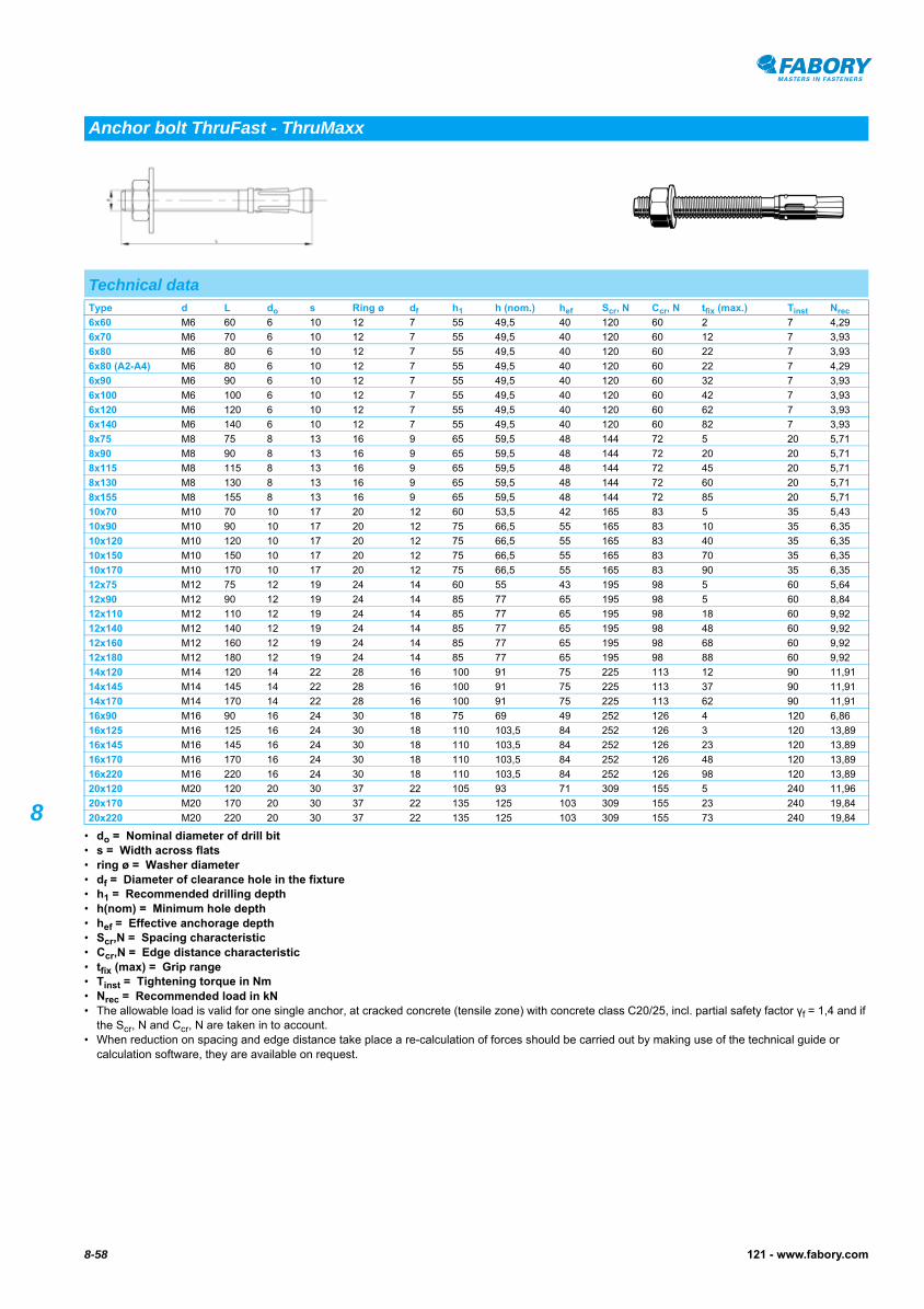
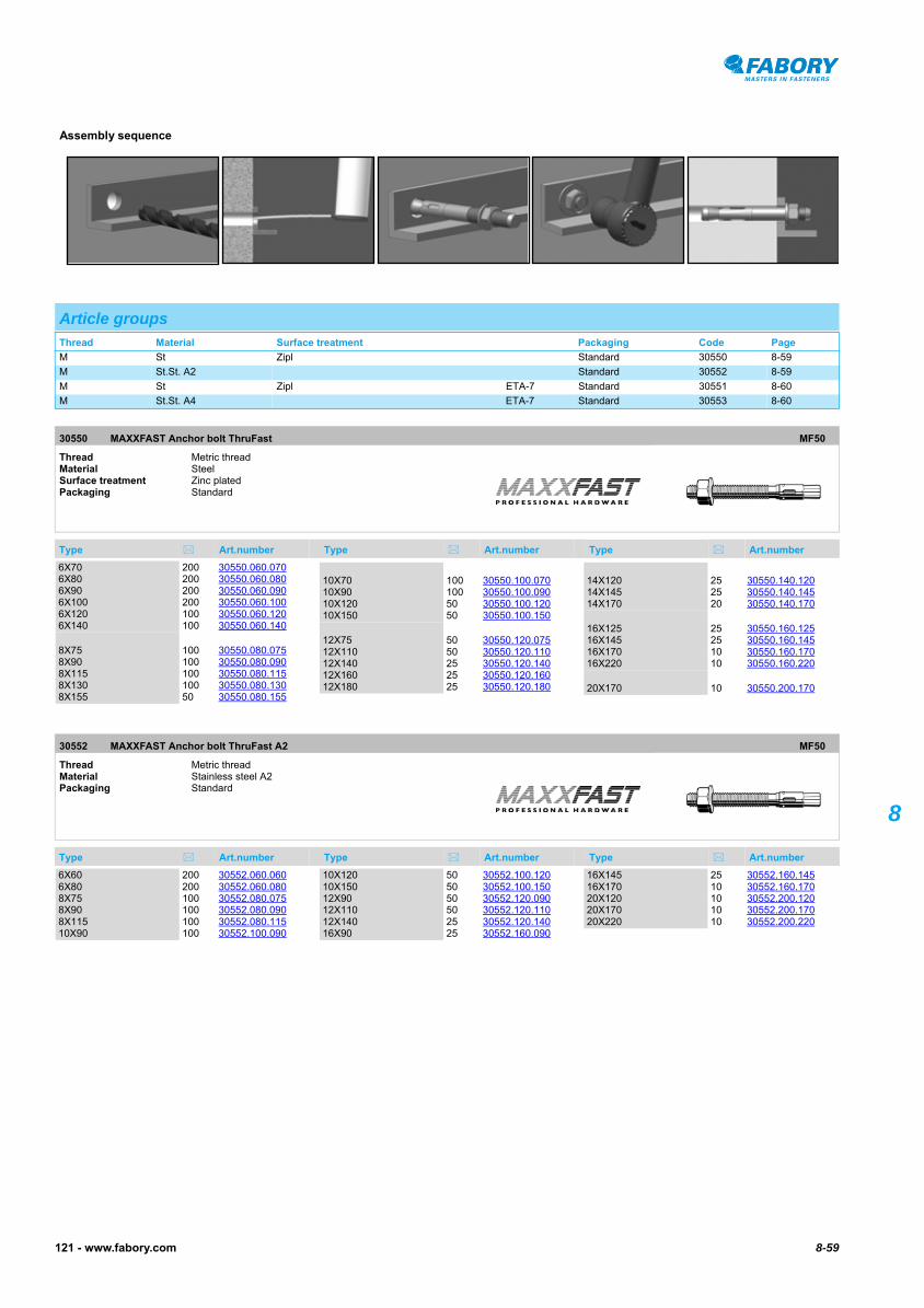
8• do = Nominal diameter of drill bit• s = Width across flats• ring ø = Washer diameter• df = Diameter of clearance hole in the fixture• h1 = Recommended drilling depth• h(nom) = Minimum hole depth• hef = Effective anchorage depth• Scr,N = Spacing characteristic• Ccr,N = Edge distance characteristic• tfix (max) = Grip range• Tinst = Tightening torque in Nm• Nrec = Recommended load in kN• The allowable load is valid for one single anchor, at cracked concrete (tensile zone) with concrete class C20/25, incl. partial safety factor γf = 1,4 and if
the Scr, N and Ccr, N are taken in to account.• When reduction on spacing and edge distance take place a re-calculation of forces should be carried out by making use of the technical guide or
calculation software, they are available on request.
Anchor bolt ThruFast - ThruMaxx
Technical dataType d L do s Ring ø df h1 h (nom.) hef Scr, N Ccr, N tfix (max.) Tinst Nrec
6x60 M6 60 6 10 12 7 55 49,5 40 120 60 2 7 4,29
6x70 M6 70 6 10 12 7 55 49,5 40 120 60 12 7 3,93
6x80 M6 80 6 10 12 7 55 49,5 40 120 60 22 7 3,93
6x80 (A2-A4) M6 80 6 10 12 7 55 49,5 40 120 60 22 7 4,29
6x90 M6 90 6 10 12 7 55 49,5 40 120 60 32 7 3,93
6x100 M6 100 6 10 12 7 55 49,5 40 120 60 42 7 3,93
6x120 M6 120 6 10 12 7 55 49,5 40 120 60 62 7 3,93
6x140 M6 140 6 10 12 7 55 49,5 40 120 60 82 7 3,93
8x75 M8 75 8 13 16 9 65 59,5 48 144 72 5 20 5,71
8x90 M8 90 8 13 16 9 65 59,5 48 144 72 20 20 5,71
8x115 M8 115 8 13 16 9 65 59,5 48 144 72 45 20 5,71
8x130 M8 130 8 13 16 9 65 59,5 48 144 72 60 20 5,71
8x155 M8 155 8 13 16 9 65 59,5 48 144 72 85 20 5,71
10x70 M10 70 10 17 20 12 60 53,5 42 165 83 5 35 5,43
10x90 M10 90 10 17 20 12 75 66,5 55 165 83 10 35 6,35
10x120 M10 120 10 17 20 12 75 66,5 55 165 83 40 35 6,35
10x150 M10 150 10 17 20 12 75 66,5 55 165 83 70 35 6,35
10x170 M10 170 10 17 20 12 75 66,5 55 165 83 90 35 6,35
12x75 M12 75 12 19 24 14 60 55 43 195 98 5 60 5,64
12x90 M12 90 12 19 24 14 85 77 65 195 98 5 60 8,84
12x110 M12 110 12 19 24 14 85 77 65 195 98 18 60 9,92
12x140 M12 140 12 19 24 14 85 77 65 195 98 48 60 9,92
12x160 M12 160 12 19 24 14 85 77 65 195 98 68 60 9,92
12x180 M12 180 12 19 24 14 85 77 65 195 98 88 60 9,92
14x120 M14 120 14 22 28 16 100 91 75 225 113 12 90 11,91
14x145 M14 145 14 22 28 16 100 91 75 225 113 37 90 11,91
14x170 M14 170 14 22 28 16 100 91 75 225 113 62 90 11,91
16x90 M16 90 16 24 30 18 75 69 49 252 126 4 120 6,86
16x125 M16 125 16 24 30 18 110 103,5 84 252 126 3 120 13,89
16x145 M16 145 16 24 30 18 110 103,5 84 252 126 23 120 13,89
16x170 M16 170 16 24 30 18 110 103,5 84 252 126 48 120 13,89
16x220 M16 220 16 24 30 18 110 103,5 84 252 126 98 120 13,89
20x120 M20 120 20 30 37 22 105 93 71 309 155 5 240 11,96
20x170 M20 170 20 30 37 22 135 125 103 309 155 23 240 19,84
20x220 M20 220 20 30 37 22 135 125 103 309 155 73 240 19,84
8-59121 - www.fabory.com
8
MAXXFAST Anchor bolt ThruFast30550
MAXXFAST Anchor bolt ThruFast30550
MAXXFAST Anchor bolt ThruFast A230552
MAXXFAST Anchor bolt ThruFast A2
Assembly sequence
Article groupsThread Material Surface treatment Packaging Code Page
M St Zipl Standard 30550 8-59
M St.St. A2 Standard 30552 8-59
M St Zipl ETA-7 Standard 30551 8-60
M St.St. A4 ETA-7 Standard 30553 8-60
30550 MAXXFAST Anchor bolt ThruFast MF50
Thread Metric threadMaterial Steel Surface treatment Zinc platedPackaging Standard
Type Art.number Type Art.number Type Art.number
6X70 200 30550.060.0706X80 200 30550.060.0806X90 200 30550.060.0906X100 200 30550.060.1006X120 100 30550.060.1206X140 100 30550.060.140
8X75 100 30550.080.0758X90 100 30550.080.0908X115 100 30550.080.1158X130 100 30550.080.1308X155 50 30550.080.155
10X70 100 30550.100.07010X90 100 30550.100.09010X120 50 30550.100.12010X150 50 30550.100.150
12X75 50 30550.120.07512X110 50 30550.120.11012X140 25 30550.120.14012X160 25 30550.120.16012X180 25 30550.120.180
14X120 25 30550.140.12014X145 25 30550.140.14514X170 20 30550.140.170
16X125 25 30550.160.12516X145 25 30550.160.14516X170 10 30550.160.17016X220 10 30550.160.220
20X170 10 30550.200.170
30552 MAXXFAST Anchor bolt ThruFast A2 MF50
Thread Metric threadMaterial Stainless steel A2Packaging Standard
Type Art.number Type Art.number Type Art.number
6X60 200 30552.060.0606X80 200 30552.060.0808X75 100 30552.080.0758X90 100 30552.080.0908X115 100 30552.080.11510X90 100 30552.100.090
10X120 50 30552.100.12010X150 50 30552.100.15012X90 50 30552.120.09012X110 50 30552.120.11012X140 25 30552.120.14016X90 25 30552.160.090
16X145 25 30552.160.14516X170 10 30552.160.17020X120 10 30552.200.12020X170 10 30552.200.17020X220 10 30552.200.220
8-60 121 - www.fabory.com
8
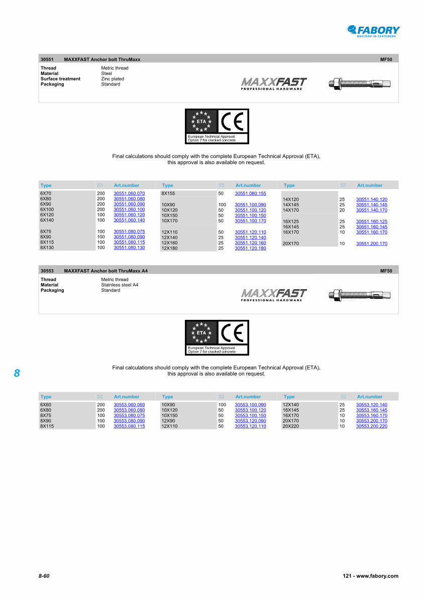
MAXXFAST Anchor bolt ThruMaxx30551
MAXXFAST Anchor bolt ThruMaxx A4
30551 MAXXFAST Anchor bolt ThruMaxx MF50
Thread Metric threadMaterial Steel Surface treatment Zinc platedPackaging Standard
Type Art.number Type Art.number Type Art.number
Final calculations should comply with the complete European Technical Approval (ETA), this approval is also available on request.
6X70 200 30551.060.0706X80 200 30551.060.0806X90 200 30551.060.0906X100 200 30551.060.1006X120 100 30551.060.1206X140 100 30551.060.140
8X75 100 30551.080.0758X90 100 30551.080.0908X115 100 30551.080.1158X130 100 30551.080.130
8X155 50 30551.080.155
10X90 100 30551.100.09010X120 50 30551.100.12010X150 50 30551.100.15010X170 50 30551.100.170
12X110 50 30551.120.11012X140 25 30551.120.14012X160 25 30551.120.16012X180 25 30551.120.180
14X120 25 30551.140.12014X145 25 30551.140.14514X170 20 30551.140.170
16X125 25 30551.160.12516X145 25 30551.160.14516X170 10 30551.160.170
20X170 10 30551.200.170
30553 MAXXFAST Anchor bolt ThruMaxx A4 MF50
Thread Metric threadMaterial Stainless steel A4Packaging Standard
Type Art.number Type Art.number Type Art.number
Final calculations should comply with the complete European Technical Approval (ETA), this approval is also available on request.
6X60 200 30553.060.0606X80 200 30553.060.0808X75 100 30553.080.0758X90 100 30553.080.0908X115 100 30553.080.115
10X90 100 30553.100.09010X120 50 30553.100.12010X150 50 30553.100.15012X90 50 30553.120.09012X110 50 30553.120.110
12X140 25 30553.120.14016X145 25 30553.160.14516X170 10 30553.160.17020X170 10 30553.200.17020X220 10 30553.200.220
8-61121 - www.fabory.com
8
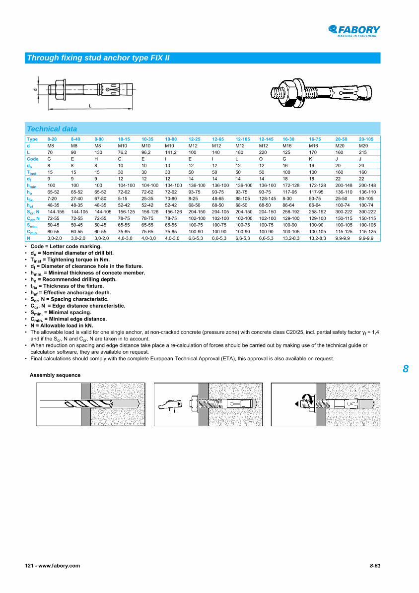
• Code = Letter code marking.• do = Nominal diameter of drill bit.• Tinst = Tightening torque in Nm.• df = Diameter of clearance hole in the fixture.• hmin. = Minimal thickness of concete member.• ho = Recommended drilling depth.• tfix = Thickness of the fixture.• hef = Effective anchorage depth.• Scr, N = Spacing characteristic.• Ccr, N = Edge distance characteristic.• Smin. = Minimal spacing.• Cmin. = Minimal edge distance.• N = Allowable load in kN.• The allowable load is valid for one single anchor, at non-cracked concrete (pressure zone) with concrete class C20/25, incl. partial safety factor γf = 1,4
and if the Scr, N and Ccr, N are taken in to account.• When reduction on spacing and edge distance take place a re-calculation of forces should be carried out by making use of the technical guide or
calculation software, they are available on request.• Final calculations should comply with the complete European Technical Approval (ETA), this approval is also available on request.
Through fixing stud anchor type FIX II
Technical dataType 8-20 8-40 8-80 10-15 10-35 10-80 12-25 12-65 12-105 12-145 16-30 16-75 20-50 20-105
d M8 M8 M8 M10 M10 M10 M12 M12 M12 M12 M16 M16 M20 M20
L 70 90 130 76,2 96,2 141,2 100 140 180 220 125 170 160 215
Code C E H C E I E I L O G K J J
do 8 8 8 10 10 10 12 12 12 12 16 16 20 20
Tinst 15 15 15 30 30 30 50 50 50 50 100 100 160 160
df 9 9 9 12 12 12 14 14 14 14 18 18 22 22
hmin 100 100 100 104-100 104-100 104-100 136-100 136-100 136-100 136-100 172-128 172-128 200-148 200-148
ho 65-52 65-52 65-52 72-62 72-62 72-62 93-75 93-75 93-75 93-75 117-95 117-95 136-110 136-110
tfix 7-20 27-40 67-80 5-15 25-35 70-80 8-25 48-65 88-105 128-145 8-30 53-75 25-50 80-105
hef 48-35 48-35 48-35 52-42 52-42 52-42 68-50 68-50 68-50 68-50 86-64 86-64 100-74 100-74
Scr, N 144-155 144-105 144-105 156-125 156-126 156-126 204-150 204-105 204-150 204-150 258-192 258-192 300-222 300-222
Ccr, N 72-55 72-55 72-55 78-75 78-75 78-75 102-100 102-100 102-100 102-100 129-100 129-100 150-115 150-115
Smin. 50-45 50-45 50-45 65-55 65-55 65-55 100-75 100-75 100-75 100-75 100-90 100-90 100-105 100-105
Cmin. 60-55 60-55 60-55 75-65 75-65 75-65 100-90 100-90 100-90 100-90 100-105 100-105 115-125 115-125
N 3,0-2,0 3,0-2,0 3,0-2,0 4,0-3,0 4,0-3,0 4,0-3,0 6,6-5,3 6,6-5,3 6,6-5,3 6,6-5,3 13,2-8,3 13,2-8,3 9,9-9,9 9,9-9,9
Assembly sequence
8-62 121 - www.fabory.com
8
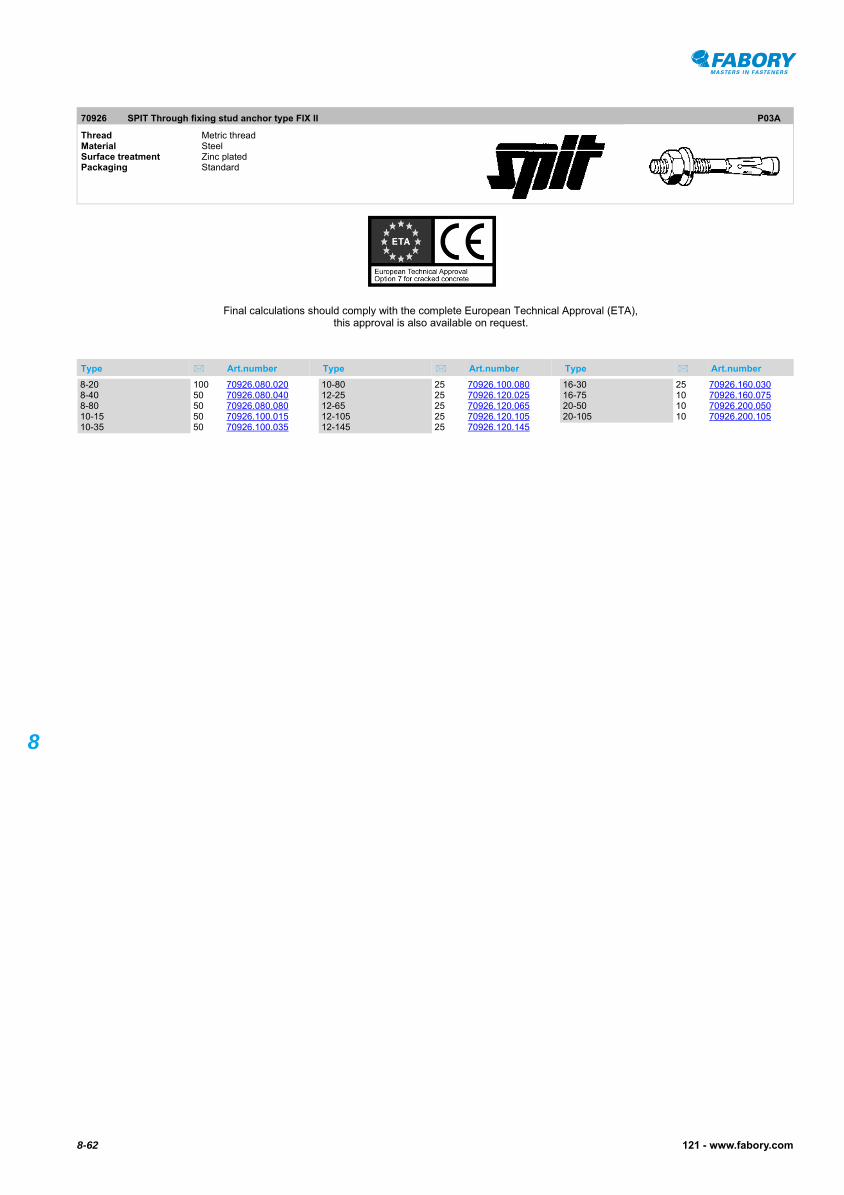
SPIT Through fixing stud anchor type FIX II
70926 SPIT Through fixing stud anchor type FIX II P03A
Thread Metric threadMaterial Steel Surface treatment Zinc platedPackaging Standard
Type Art.number Type Art.number Type Art.number
Final calculations should comply with the complete European Technical Approval (ETA), this approval is also available on request.
8-20 100 70926.080.0208-40 50 70926.080.0408-80 50 70926.080.08010-15 50 70926.100.01510-35 50 70926.100.035
10-80 25 70926.100.08012-25 25 70926.120.02512-65 25 70926.120.06512-105 25 70926.120.10512-145 25 70926.120.145
16-30 25 70926.160.03016-75 10 70926.160.07520-50 10 70926.200.05020-105 10 70926.200.105

8-63121 - www.fabory.com
8
• do = Nominal diameter of drill bit.• tfix = Grip range.• hef = Effective anchorage depth.• Min. td = Recommended drilling depth.• kN = Load in kN.• The allowable load is valid for one single anchor, at cracked concrete (tensile zone) with concrete class C20/25, incl. partial safety factor γf = 1,4 and if
the Scr, N and Ccr, N are taken in to account.
Bolt type FBN II
Technical dataType d L do tfix hef Min. td Ring ø kN
FBN II 6/5 M6 50 6 5 30 45 12X1,6 1,5
FBN II 6/10 M6 55 6 10 30 50 12X1,6 1,5
FBN II 6/30 M6 75 6 30 30 70 12X1,6 1,5
FBN II 8/5 M8 66 8 5 40 61 16X1,6 2,9-6,1
FBN II 8/10 M8 71 8 10 40 66 16X1,6 2,9-6,1
FBN II 8/20 M8 81 8 20 40 76 16X1,6 2,9-6,1
FBN II 8/30 M8 91 8 30 40 86 16X1,6 2,9-6,1
FBN II 8/50 M8 111 8 50 40 106 16X1,6 2,9-6,1
FBN II 8/70 M8 131 8 70 40 126 16X1,6 2,9-6,1
FBN II 8/100 M8 161 8 100 40 156 16X1,6 2,9-6,1
FBN II 8/5 K M8 56 8 5 30 51 16X1,6 2,9-6,1
FBN II 8/10 K M8 61 8 10 30 56 16X1,6 2,9-6,1
FBN II 8/30 K M8 81 8 30 30 76 16X1,6 2,9-6,1
FBN II 10/10 M10 86 10 10 50 78 20X2 6,1-8,5
FBN II 10/20 M10 96 10 20 50 88 20X2 6,1-8,5
FBN II 10/30 M10 106 10 30 50 98 20X2 6,1-8,5
FBN II 10/50 M10 126 10 50 50 118 20X2 6,1-8,5
FBN II 10/70 M10 146 10 70 50 138 20X2 6,1-8,5
FBN II 10/100 M10 176 10 100 50 168 20X2 6,1-8,5
FBN II 10/140 M10 216 10 140 50 208 20X2 6,1-8,5
FBN II 10/160 M10 236 10 160 50 228 20X2 6,1-8,5
FBN II 10/5 K M10 71 10 5 40 63 20X2 6,1-8,5
FBN II 10/10 K M10 76 10 10 40 68 20X2 6,1-8,5
FBN II 10/30 K M10 96 10 30 40 88 20X2 6,1-8,5
FBN II 12/10 M12 106 12 10 65 95 24X2,5 8,5-12,6
FBN II 12/20 M12 116 12 20 65 105 24X2,5 8,5-12,6
FBN II 12/30 M12 126 12 30 65 115 24X2,5 8,5-12,6
FBN II 12/50 M12 146 12 50 65 135 24X2,5 8,5-12,6
FBN II 12/80 M12 176 12 80 65 165 24X2,5 8,5-12,6
FBN II 12/100 M12 196 12 100 65 185 24X2,5 8,5-12,6
FBN II 12/120 M12 216 12 120 65 205 24X2,5 8,5-12,6
FBN II 12/140 M12 236 12 140 65 225 24X2,5 8,5-12,6
FBN II 12/160 M12 256 12 160 65 245 24X2,5 8,5-12,6
FBN II 12/5 K M12 86 12 5 50 75 24X2,5 8,5-12,6
FBN II 12/10 K M12 91 12 10 50 80 24X2,5 8,5-12,6
FBN II 12/30 K M12 111 12 30 50 100 24X2,5 8,5-12,6
FBN 16/10 M16 130 16 10 80 114 30X3 12,6-17,2
FBN II 16/25 M16 145 16 25 80 129 30X3 12,6-17,2
FBN II 16/50 M16 170 16 50 80 154 30X3 12,6-17,2
FBN II 16/80 M16 200 16 80 80 184 30X3 12,6-17,2
FBN II 16/100 M16 220 16 100 80 204 30X3 12,6-17,2
FBN II 16/140 M16 260 16 140 80 244 30X3 12,6-17,2
FBN II 16/160 M16 280 16 160 80 264 30X3 12,6-17,2
FBN II 16/200 M16 320 16 200 80 304 30X3 12,6-17,2
FBN II 16/15 K M16 120 16 15 65 104 30X3 12,6-17,2
FBN II 16/25 K M16 130 16 25 65 114 30X3 12,6-17,2
FBN II 20/30 M20 184 20 30 105 165 37X3 17,2-25,8
FBN II 20/60 M20 214 20 60 105 195 37X3 17,2-25,8
FBN II 20/80 M20 234 20 80 105 215 37X3 17,2-25,8
FBN II 20/120 M20 274 20 120 105 255 37X3 17,2-25,8
FBN II 20/10 K M20 139 20 10 80 120 37X3 17,2-25,8

8-64 121 - www.fabory.com
8
• When reduction on spacing and edge distance take place a re-calculation of forces should be carried out by making use of the technical guide or calculation software, they are available on request.
• Final calculations should comply with the complete European Technical Approval (ETA), this approval is also available on request.
FISCHER Bolt type FB II
Assembly sequence
Article groupsThread Material Surface treatment Packaging Code Page
M St Zipl Standard 63324 8-64
M St.St. A4 Standard 63325 8-65
63324 FISCHER Bolt type FB II N03A
Thread Metric threadMaterial Steel Surface treatment Zinc platedPackaging Standard
Type Art.number Type Art.number Type Art.number
Final calculations should comply with the complete European Technical Approval (ETA), this approval is also available on request.
6/5 100 63324.060.0056/10 100 63324.060.0106/30 100 63324.060.0308/5 (8X66) 50 63324.080.0058/10 (8X71) 50 63324.080.0108/20 (8X81) 50 63324.080.0208/30 (8X91) 50 63324.080.0308/50 (8X111) 50 63324.080.0508/70 (8X131) 20 63324.080.0708/100 (8X161) 20 63324.080.1008/5 K (8X56) 50 63324.081.0058/10 K (8X61) 50 63324.081.01010/10 (10X86) 50 63324.100.01010/20 (10X96) 50 63324.100.02010/30 (10X106) 50 63324.100.03010/50 (10X126) 20 63324.100.050
10/70 (10X146) 20 63324.100.07010/100 (10X176) 20 63324.100.10010/140 (10X216) 20 63324.100.14010/160 (10X236) 20 63324.100.16010/5 K (10X71) 50 63324.101.00510/10 K (10X76) 50 63324.101.01012/10 (12X106) 20 63324.120.01012/20 (12X116) 20 63324.120.02012/30 (12X126) 20 63324.120.03012/50 (12X146) 20 63324.120.05012/80 (12X176) 20 63324.120.08012/100 (12X196) 20 63324.120.10012/120 (12X216) 20 63324.120.12012/140 (12X236) 20 63324.120.14012/160 (12X256) 20 63324.120.16012/5 K (12X86) 20 63324.121.005
12/10 K (12X91) 20 63324.121.01012/30 K (12X111) 20 63324.121.03016/25 (16X145) 10 63324.160.02516/50 (16X170) 10 63324.160.05016/80 (16X200) 10 63324.160.08016/100 (16X220) 10 63324.160.10016/140 (16X260) 10 63324.160.14016/160 (16X280) 10 63324.160.16016/200 (16X320) 10 63324.160.20016/15 K (16X120) 10 63324.161.01516/25 K (16X130) 10 63324.161.02520/30 (20X184) 10 63324.200.03020/60 (20X214) 10 63324.200.06020/80 (20X234) 10 63324.200.08020/120 (20X274) 10 63324.200.12020/10 K (20X139) 10 63324.201.010

8-65121 - www.fabory.com
8
FISCHER Bolt type FB II
63325 FISCHER Bolt type FB II N03A
Thread Metric threadMaterial Stainless steel A4Packaging Standard
Type Art.number Type Art.number Type Art.number
Final calculations should comply with the complete European Technical Approval (ETA), this approval is also available on request.
6/10 (6X55) 100 63325.060.0106/30 (6X75) 100 63325.060.0308/10 (8X71) 50 63325.080.0108/30 (8X91) 50 63325.080.0308/50 (8X111) 50 63325.080.05010/20 (10X96) 50 63325.100.020
10/30 (10X106) 50 63325.100.03010/50 (10X126) 20 63325.100.05010/100 (10X176) 20 63325.100.10012/20 (12X116) 20 63325.120.02012/30 (12X126) 20 63325.120.03012/50 (12X146) 20 63325.120.050
12/100 (12X196) 20 63325.120.10016/10 (16X130) 10 63325.160.01016/25 (16X145) 10 63325.160.02516/50 (16X170) 10 63325.160.050
8-66 121 - www.fabory.com
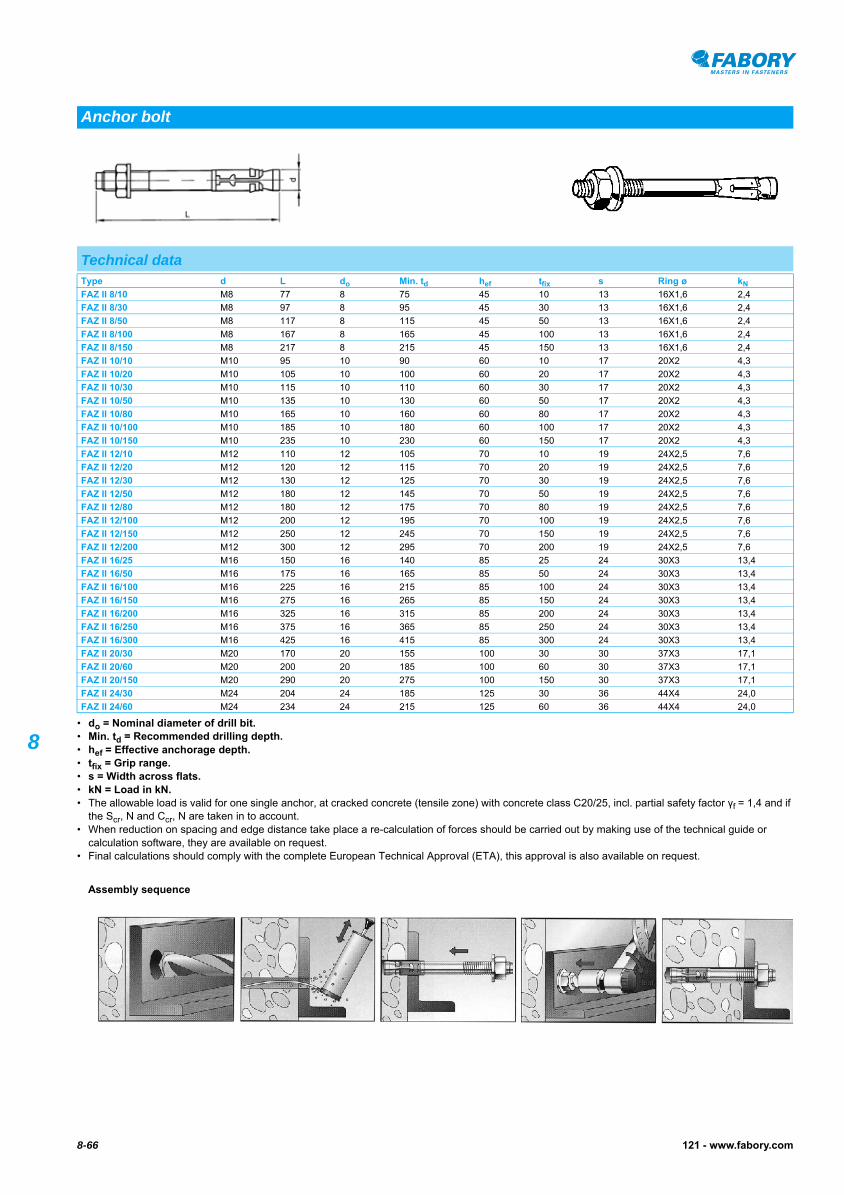
8• do = Nominal diameter of drill bit.• Min. td = Recommended drilling depth.• hef = Effective anchorage depth.• tfix = Grip range.• s = Width across flats.• kN = Load in kN.• The allowable load is valid for one single anchor, at cracked concrete (tensile zone) with concrete class C20/25, incl. partial safety factor γf = 1,4 and if
the Scr, N and Ccr, N are taken in to account.• When reduction on spacing and edge distance take place a re-calculation of forces should be carried out by making use of the technical guide or
calculation software, they are available on request.• Final calculations should comply with the complete European Technical Approval (ETA), this approval is also available on request.
Anchor bolt
Technical dataType d L do Min. td hef tfix s Ring ø kN
FAZ II 8/10 M8 77 8 75 45 10 13 16X1,6 2,4
FAZ II 8/30 M8 97 8 95 45 30 13 16X1,6 2,4
FAZ II 8/50 M8 117 8 115 45 50 13 16X1,6 2,4
FAZ II 8/100 M8 167 8 165 45 100 13 16X1,6 2,4
FAZ II 8/150 M8 217 8 215 45 150 13 16X1,6 2,4
FAZ II 10/10 M10 95 10 90 60 10 17 20X2 4,3
FAZ II 10/20 M10 105 10 100 60 20 17 20X2 4,3
FAZ II 10/30 M10 115 10 110 60 30 17 20X2 4,3
FAZ II 10/50 M10 135 10 130 60 50 17 20X2 4,3
FAZ II 10/80 M10 165 10 160 60 80 17 20X2 4,3
FAZ II 10/100 M10 185 10 180 60 100 17 20X2 4,3
FAZ II 10/150 M10 235 10 230 60 150 17 20X2 4,3
FAZ II 12/10 M12 110 12 105 70 10 19 24X2,5 7,6
FAZ II 12/20 M12 120 12 115 70 20 19 24X2,5 7,6
FAZ II 12/30 M12 130 12 125 70 30 19 24X2,5 7,6
FAZ II 12/50 M12 180 12 145 70 50 19 24X2,5 7,6
FAZ II 12/80 M12 180 12 175 70 80 19 24X2,5 7,6
FAZ II 12/100 M12 200 12 195 70 100 19 24X2,5 7,6
FAZ II 12/150 M12 250 12 245 70 150 19 24X2,5 7,6
FAZ II 12/200 M12 300 12 295 70 200 19 24X2,5 7,6
FAZ II 16/25 M16 150 16 140 85 25 24 30X3 13,4
FAZ II 16/50 M16 175 16 165 85 50 24 30X3 13,4
FAZ II 16/100 M16 225 16 215 85 100 24 30X3 13,4
FAZ II 16/150 M16 275 16 265 85 150 24 30X3 13,4
FAZ II 16/200 M16 325 16 315 85 200 24 30X3 13,4
FAZ II 16/250 M16 375 16 365 85 250 24 30X3 13,4
FAZ II 16/300 M16 425 16 415 85 300 24 30X3 13,4
FAZ II 20/30 M20 170 20 155 100 30 30 37X3 17,1
FAZ II 20/60 M20 200 20 185 100 60 30 37X3 17,1
FAZ II 20/150 M20 290 20 275 100 150 30 37X3 17,1
FAZ II 24/30 M24 204 24 185 125 30 36 44X4 24,0
FAZ II 24/60 M24 234 24 215 125 60 36 44X4 24,0
Assembly sequence
8-67121 - www.fabory.com
8
FISCHER Anchor bolt type FAZ II
63323 FISCHER Anchor bolt type FAZ II N03A
Thread Metric threadMaterial Steel Surface treatment Zinc platedPackaging Standard
Type Art.number Type Art.number Type Art.number
Final calculations should comply with the complete European Technical Approval (ETA), this approval is also available on request.
FAZII8/10 50 63323.080.010FAZII8/30 50 63323.080.030FAZII8/50 50 63323.080.050FAZII8/100 25 63323.080.100FAZII10/10 50 63323.100.010FAZII10/20 25 63323.100.020FAZII10/30 25 63323.100.030FAZII10/50 20 63323.100.050FAZII10/80 20 63323.100.080
FAZII10/100 20 63323.100.100FAZII12/10 20 63323.120.010FAZII12/20 20 63323.120.020FAZII12/30 20 63323.120.030FAZII12/50 20 63323.120.050FAZII12/80 20 63323.120.080FAZII12/100 20 63323.120.100FAZII12/200 10 63323.120.200FAZII16/25 10 63323.160.025
FAZII16/50 10 63323.160.050FAZII16/100 10 63323.160.100FAZII16/200 10 63323.160.200FAZII16/250 10 63323.160.250FAZII16/300 10 63323.160.300FAZII20/30 5 63323.200.030FAZII20/60 5 63323.200.060FAZII24/30 5 63323.240.030FAZII24/60 5 63323.240.060
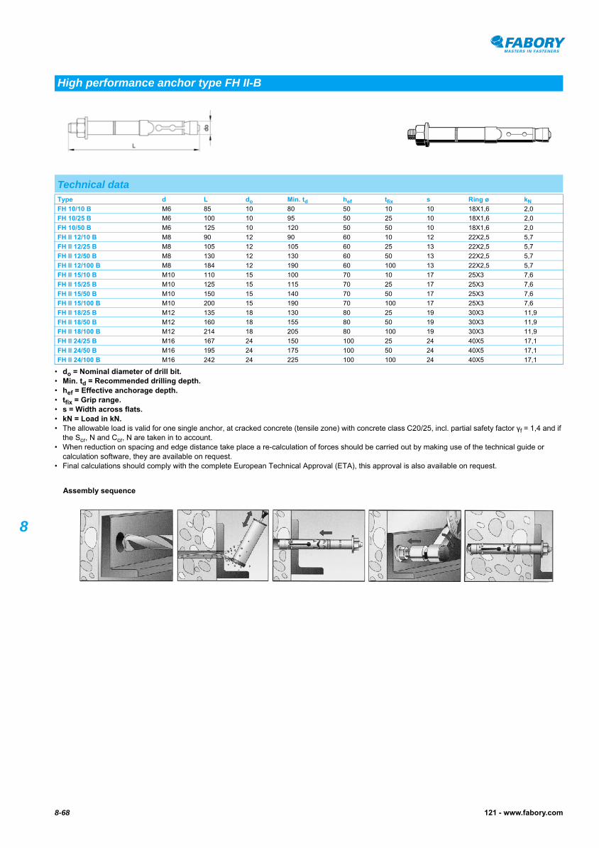
8-68 121 - www.fabory.com
8
• do = Nominal diameter of drill bit.• Min. td = Recommended drilling depth.• hef = Effective anchorage depth.• tfix = Grip range.• s = Width across flats.• kN = Load in kN.• The allowable load is valid for one single anchor, at cracked concrete (tensile zone) with concrete class C20/25, incl. partial safety factor γf = 1,4 and if
the Scr, N and Ccr, N are taken in to account.• When reduction on spacing and edge distance take place a re-calculation of forces should be carried out by making use of the technical guide or
calculation software, they are available on request.• Final calculations should comply with the complete European Technical Approval (ETA), this approval is also available on request.
High performance anchor type FH II-B
Technical dataType d L do Min. td hef tfix s Ring ø kN
FH 10/10 B M6 85 10 80 50 10 10 18X1,6 2,0
FH 10/25 B M6 100 10 95 50 25 10 18X1,6 2,0
FH 10/50 B M6 125 10 120 50 50 10 18X1,6 2,0
FH II 12/10 B M8 90 12 90 60 10 12 22X2,5 5,7
FH II 12/25 B M8 105 12 105 60 25 13 22X2,5 5,7
FH II 12/50 B M8 130 12 130 60 50 13 22X2,5 5,7
FH II 12/100 B M8 184 12 190 60 100 13 22X2,5 5,7
FH II 15/10 B M10 110 15 100 70 10 17 25X3 7,6
FH II 15/25 B M10 125 15 115 70 25 17 25X3 7,6
FH II 15/50 B M10 150 15 140 70 50 17 25X3 7,6
FH II 15/100 B M10 200 15 190 70 100 17 25X3 7,6
FH II 18/25 B M12 135 18 130 80 25 19 30X3 11,9
FH II 18/50 B M12 160 18 155 80 50 19 30X3 11,9
FH II 18/100 B M12 214 18 205 80 100 19 30X3 11,9
FH II 24/25 B M16 167 24 150 100 25 24 40X5 17,1
FH II 24/50 B M16 195 24 175 100 50 24 40X5 17,1
FH II 24/100 B M16 242 24 225 100 100 24 40X5 17,1
Assembly sequence

8-69121 - www.fabory.com
8
FISCHER High performance anchor type FH II-B
63421 FISCHER High performance anchor type FH II-B N03A
Thread Metric threadMaterial Steel Surface treatment Zinc platedPackaging Standard
Type Art.number Type Art.number Type Art.number
Final calculations should comply with the complete European Technical Approval (ETA), this approval is also available on request.
FH II 12/10 B 50 63421.120.010FH II 12/25 B 50 63421.120.025FH II 12/50 B 25 63421.120.050FH II 12/100 B 25 63421.120.100FH II 15/10 B 25 63421.150.010
FH II 15/25 B 25 63421.150.025FH II 15/50 B 25 63421.150.050FH II 15/100 B 20 63421.150.100FH II 18/25 B 20 63421.180.025FH II 18/50 B 20 63421.180.050
FH II 18/100 B 10 63421.180.100FH II 24/25 B 10 63421.240.025FH II 24/50 B 10 63421.240.050FH II 24/100 B 5 63421.240.100
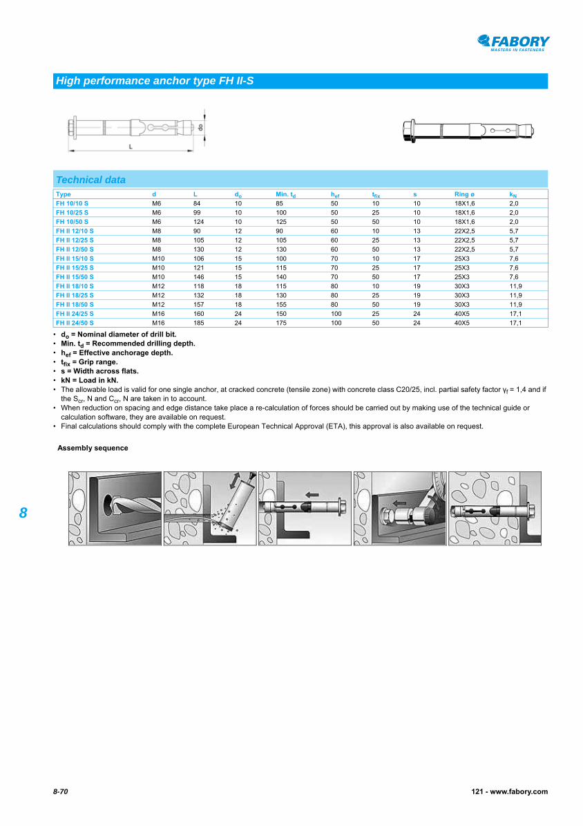
8-70 121 - www.fabory.com
8
• do = Nominal diameter of drill bit.• Min. td = Recommended drilling depth.• hef = Effective anchorage depth.• tfix = Grip range.• s = Width across flats.• kN = Load in kN.• The allowable load is valid for one single anchor, at cracked concrete (tensile zone) with concrete class C20/25, incl. partial safety factor γf = 1,4 and if
the Scr, N and Ccr, N are taken in to account.• When reduction on spacing and edge distance take place a re-calculation of forces should be carried out by making use of the technical guide or
calculation software, they are available on request.• Final calculations should comply with the complete European Technical Approval (ETA), this approval is also available on request.
High performance anchor type FH II-S
Technical dataType d L do Min. td hef tfix s Ring ø kN
FH 10/10 S M6 84 10 85 50 10 10 18X1,6 2,0
FH 10/25 S M6 99 10 100 50 25 10 18X1,6 2,0
FH 10/50 S M6 124 10 125 50 50 10 18X1,6 2,0
FH II 12/10 S M8 90 12 90 60 10 13 22X2,5 5,7
FH II 12/25 S M8 105 12 105 60 25 13 22X2,5 5,7
FH II 12/50 S M8 130 12 130 60 50 13 22X2,5 5,7
FH II 15/10 S M10 106 15 100 70 10 17 25X3 7,6
FH II 15/25 S M10 121 15 115 70 25 17 25X3 7,6
FH II 15/50 S M10 146 15 140 70 50 17 25X3 7,6
FH II 18/10 S M12 118 18 115 80 10 19 30X3 11,9
FH II 18/25 S M12 132 18 130 80 25 19 30X3 11,9
FH II 18/50 S M12 157 18 155 80 50 19 30X3 11,9
FH II 24/25 S M16 160 24 150 100 25 24 40X5 17,1
FH II 24/50 S M16 185 24 175 100 50 24 40X5 17,1
Assembly sequence
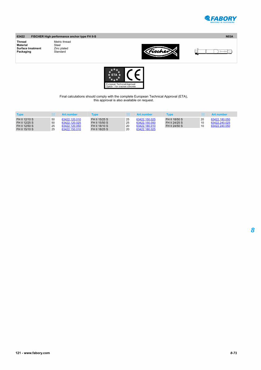
8-71121 - www.fabory.com
8
FISCHER High performance anchor type FH II-S
63422 FISCHER High performance anchor type FH II-S N03A
Thread Metric threadMaterial Steel Surface treatment Zinc platedPackaging Standard
Type Art.number Type Art.number Type Art.number
Final calculations should comply with the complete European Technical Approval (ETA), this approval is also available on request.
FH II 12/10 S 50 63422.120.010FH II 12/25 S 50 63422.120.025FH II 12/50 S 25 63422.120.050FH II 15/10 S 25 63422.150.010
FH II 15/25 S 25 63422.150.025FH II 15/50 S 25 63422.150.050FH II 18/10 S 20 63422.180.010FH II 18/25 S 20 63422.180.025
FH II 18/50 S 20 63422.180.050FH II 24/25 S 10 63422.240.025FH II 24/50 S 10 63422.240.050

8-72 121 - www.fabory.com
8
• High permissible for assembly in tension zones!• For further technical data the approval is available on request.
FISCHER-ZYKON Bolt anchor type FZA
Bolt anchor
Technical dataType FZA 12x40 M8/15 FZA 12x50 M8/15 FZA 14x40 M10/25 FZA 14x60 M10/25 FZA 18x80 M12/25
d M8 M8 M10 M10 M12
Drill ø (type FZUB) 12 12 14 14 18
Drill depth 40 50 40 60 80
Grip range (max.) 15 15 25 25 25
Allowable load in kN
Concrete ≥ C20/25 1,94 1,94 2,84 4,24 7,57
63445 FISCHER-ZYKON Bolt anchor type FZA N03B
Thread Metric threadMaterial Steel Surface treatment Zinc platedPackaging Standard
Assembly sequence
Type Art.number Type Art.number Type Art.number
Final calculations should comply with the complete European Technical Approval (ETA), this approval is also available on request.
FZA 12X40 M8/15 25 63445.120.040FZA 12X50 M8/15 20 63445.120.050
FZA 14X40 M10/25 25 63445.140.040FZA 14X60 M10/25 10 63445.140.060
FZA 18X80 M12/25 10 63445.180.080

8-73121 - www.fabory.com
8
FISCHER-ZYKON Bolt anchor installation tool type FZA63690
FISCHER-ZYKON Bolt anchor installation tool type FZA
Bolt anchor installation tool
63690 FISCHER-ZYKON Bolt anchor installation tool type FZA N03A
Packaging Standard
Type Art.number
FZUB 12X40 1 63690.100.005 • Conical, correct drill-hole geometry• Drilling and undercutting in one single operation• With elastic depth stop• SDS-plus drive end
FZUB 14X40 1 63690.100.010 • Conical, correct drill-hole geometry• Drilling and undercutting in one single operation• With elastic depth stop• SDS-plus drive end
FZUB 12X50 1 63690.100.015 • Conical, correct drill-hole geometry• Drilling and undercutting in one single operation• With elastic depth stop• SDS-plus drive end
FZUB 14X60 1 63690.100.020 • Conical, correct drill-hole geometry• Drilling and undercutting in one single operation• With elastic depth stop• SDS-plus drive end
FZUB 18X80 1 63690.100.025 • Conical, correct drill-hole geometry• Drilling and undercutting in one single operation• With elastic depth stop• SDS-plus drive end
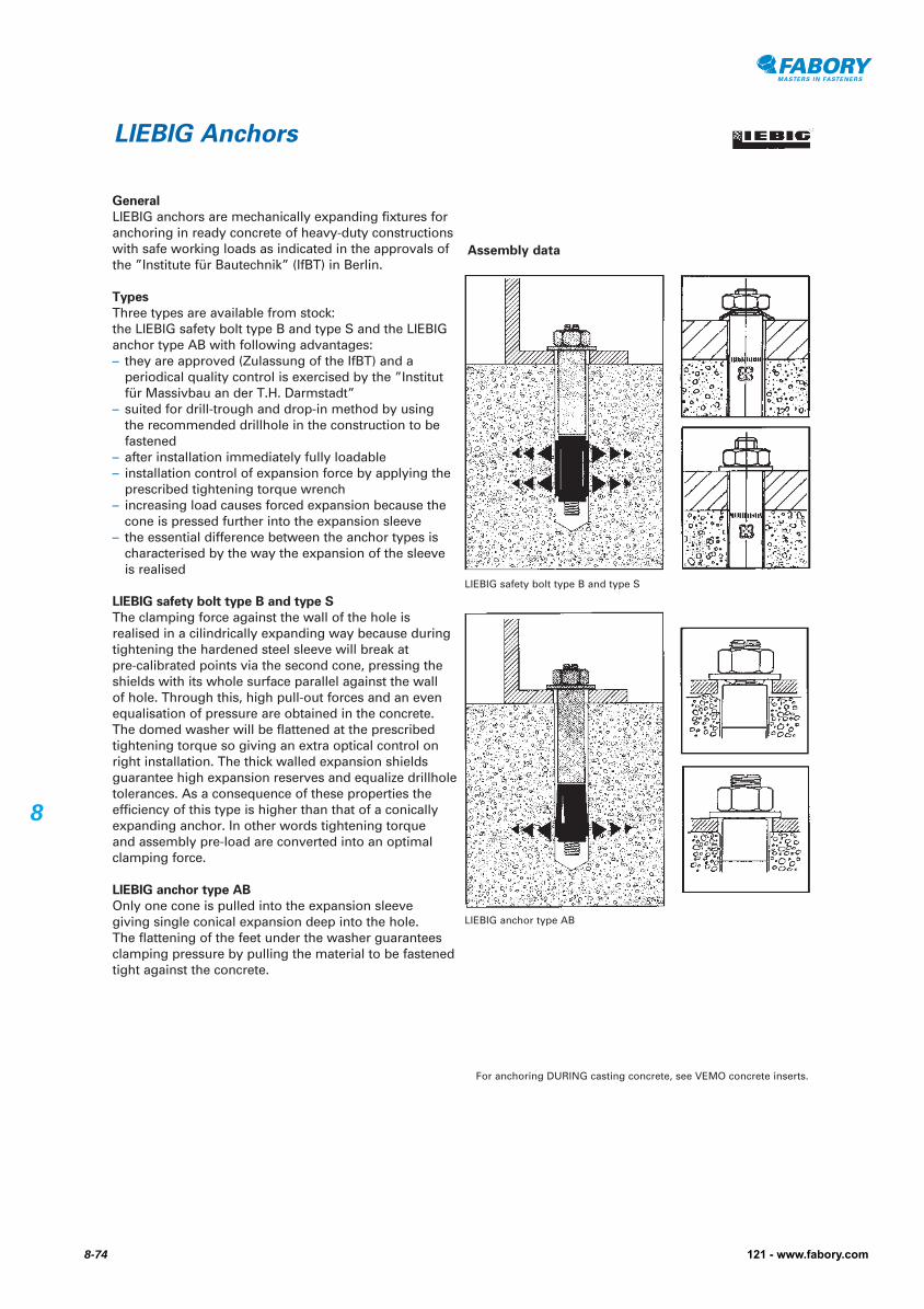
General
LIEBIG anchors are mechanically expanding fixtures for anchoring in ready concrete of heavy-duty constructions with safe working loads as indicated in the approvals of the ”Institute für Bautechnik” (IfBT) in Berlin.
Types
Three types are available from stock: the LIEBIG safety bolt type B and type S and the LIEBIG anchor type AB with following advantages:– they are approved (Zulassung of the IfBT) and a
periodical quality control is exercised by the ”Institut für Massivbau an der T.H. Darmstadt”
– suited for drill-trough and drop-in method by using the recommended drillhole in the construction to be fastened
– after installation immediately fully loadable– installation control of expansion force by applying the
prescribed tightening torque wrench– increasing load causes forced expansion because the
cone is pressed further into the expansion sleeve– the essential difference between the anchor types is
characterised by the way the expansion of the sleeve is realised
LIEBIG safety bolt type B and type S
The clamping force against the wall of the hole is realised in a cilindrically expanding way because during tightening the hardened steel sleeve will break at pre-calibrated points via the second cone, pressing the shields with its whole surface parallel against the wall of hole. Through this, high pull-out forces and an even equalisation of pressure are obtained in the concrete. The domed washer will be flattened at the prescribed tightening torque so giving an extra optical control on right installation. The thick walled expansion shields guarantee high expansion reserves and equalize drillhole tolerances. As a consequence of these properties the efficiency of this type is higher than that of a conically expanding anchor. In other words tightening torque and assembly pre-load are converted into an optimal clamping force.
LIEBIG anchor type AB
Only one cone is pulled into the expansion sleeve giving single conical expansion deep into the hole. The flattening of the feet under the washer guarantees clamping pressure by pulling the material to be fastened tight against the concrete.
LIEBIG Anchors
LIEBIG safety bolt type B and type S
Assembly data
LIEBIG anchor type AB
For anchoring DURING casting concrete, see VEMO concrete inserts.
8-74 121 - www.fabory.com
8

8-75121 - www.fabory.com
8
• kN = Allowable load in kN in 20/25.
Safety bolt type B
Technical dataType d1 L d2 Drill depth (min.) Drill ø in construction Grip range (max.) kN
B M6-10/45/5 M6 70 10 60 12 5 2,4
B M6-10/45/15 M6 80 10 60 12 15 2,4
B M6-10/45/40 M6 105 10 60 12 40 2,4
B M8-12/55/5 M8 85 12 70 14 5 3,6
B M8-12/55/15 M8 95 12 70 14 15 3,6
B M8-12/55/40 M8 120 12 70 14 40 3,6
B M8-12/55/65 M8 145 12 70 14 65 3,6
B M8-12/55/100 M8 180 12 70 14 100 3,6
B M10-15/70/5 M10 100 15 85 17 5 7,6
B M10-15/70/15 M10 110 15 85 17 15 7,6
B M10-15/70/40 M10 135 15 85 17 40 7,6
B M10-15/70/65 M10 160 15 85 17 65 7,6
B M10-15/70/100 M10 195 15 85 17 100 7,6
B M10-15/70/140 M10 235 15 85 17 140 7,6
B M12-20/80/5 M12 120 20 100 21 5 12,3
B M12-20/80/15 M12 130 20 100 21 15 12,3
B M12-20/80/40 M12 155 20 100 21 40 12,3
B M12-20/80/65 M12 180 20 100 21 65 12,3
B M12-20/80/100 M12 215 20 100 21 100 12,3
B M12-20/80/140 M12 255 20 100 21 140 12,3
B M16-25/100/5 M16 150 25 125 26 5 17,1
B M16-25/100/15 M16 160 25 125 26 15 17,1
B M16-25/100/40 M16 185 25 125 26 40 17,1
B M16-25/100/65 M16 210 25 125 26 65 17,1
B M16-25/100/100 M16 245 25 125 26 100 17,1
B M20-30/125/15 M20 180 30 150 32 15 18,6
B M20-30/125/40 M20 205 30 150 32 40 18,6
B M20-30/125/65 M20 230 30 150 32 65 18,6
B M20-30/125/100 M20 265 30 150 32 100 18,6
10015 LIEBIG Safety bolt type B P05A
Thread Metric threadMaterial Steel Class 8.8Surface treatment Zinc platedPackaging Standard
Type Art.number Type Art.number Type Art.number
Final calculations should comply with the complete European Technical Approval (ETA), this approval is also available on request.
B M6-10/45/5 50 10015.010.005B M6-10/45/15 50 10015.010.015B M6-10/45/40 50 10015.010.040
B M8-12/55/5 25 10015.012.005B M8-12/55/15 25 10015.012.015B M8-12/55/40 25 10015.012.040B M8-12/55/65 25 10015.012.065
B M8-12/55/100 25 10015.012.100
B M10-15/70/5 25 10015.015.005B M10-15/70/15 25 10015.015.015B M10-15/70/40 10 10015.015.040B M10-15/70/65 10 10015.015.065B M10-15/70/100 25 10015.015.100B M10-15/70/140 25 10015.015.140
B M12-20/80/5 10 10015.020.005B M12-20/80/15 10 10015.020.015B M12-20/80/40 10 10015.020.040B M12-20/80/65 10 10015.020.065B M12-20/80/100 20 10015.020.100B M12-20/80/140 20 10015.020.140

10015 LIEBIG Safety bolt type B
Type Art.number Type Art.number Type Art.number
8-76 121 - www.fabory.com
8
LIEBIG Safety bolt type B
B M16-25/100/5 5 10015.025.005B M16-25/100/15 5 10015.025.015B M16-25/100/40 5 10015.025.040B M16-25/100/65 10 10015.025.065
B M16-25/100/100 10 10015.025.100
B M20-30/125/15 5 10015.030.015B M20-30/125/40 5 10015.030.040
B M20-30/125/65 5 10015.030.065B M20-30/125/100 5 10015.030.100

8-77121 - www.fabory.com
8
• kN = Allowable load in kN in C20/25.
LIEBIG Safety bolt type S
Safety bolt type S
Technical dataType d1 L d2 Drill depth (min.) Drill ø in construction Grip range (max.) kN
S-M6-10/45/5 M6 70 10 60 12 5 2,4
S-M6-10/45/15 M6 80 10 60 12 15 2,4
S-M6-10/45/40 M6 105 10 60 12 40 2,4
S-M8-12/55/5 M8 80 12 70 14 5 3,6
S-M8-12/55/15 M8 90 12 70 14 15 3,6
S-M8-12/55/40 M8 115 12 70 14 40 3,6
S-M8-12/55/65 M8 140 12 70 14 65 3,6
S-M10-15/70/5 M10 95 15 85 17 5 7,6
S-M10-15/70/15 M10 105 15 85 17 15 7,6
S-M10-15/70/40 M10 130 15 85 17 40 7,6
S-M10-15/70/65 M10 155 15 85 17 65 7,6
S-M12-20/80/5 M12 113 20 100 21 5 12,3
S-M12-20/80/15 M12 123 20 100 21 15 12,3
S-M12-20/80/40 M12 148 20 100 21 40 12,3
S-M12-20/80/65 M12 173 20 100 21 65 12,3
S-M16-25/100/5 M16 145 25 125 26 5 17,1
S-M16-25/100/15 M16 155 25 125 26 15 17,1
S-M16-25/100/40 M16 180 25 125 26 40 17,1
S-M16-25/100/65 M16 205 25 125 26 65 17,1
S-M20-30/125/15 M20 180 30 150 32 15 18,6
S-M20-30/125/40 M20 205 30 150 32 40 18,6
10025 LIEBIG Safety bolt type S P05A
Thread Metric threadMaterial Steel Class 8.8Surface treatment Zinc platedPackaging Standard
Type Art.number Type Art.number Type Art.number
Final calculations should comply with the complete European Technical Approval (ETA), this approval is also available on request.
S M6-10/45/5 50 10025.010.005S M6-10/45/15 50 10025.010.015S M6-10/45/40 50 10025.010.045
S M8-12/55/5 25 10025.012.005S M8-12/55/15 25 10025.012.015S M8-12/55/40 25 10025.012.040S M8-12/55/65 25 10025.012.065
S M10-15/70/5 25 10025.015.005S M10-15/70/15 25 10025.015.015S M10-15/70/40 10 10025.015.040S M10-15/70/65 10 10025.015.065
S M12-20/80/5 10 10025.020.005S M12-20/80/15 10 10025.020.015S M12-20/80/40 10 10025.020.040S M12-20/80/65 10 10025.020.065
S M16-25/100/5 5 10025.025.005S M16-25/100/15 5 10025.025.015S M16-25/100/40 5 10025.025.040
S M20-30/125/15 5 10025.030.015S M20-30/125/40 5 10025.030.040
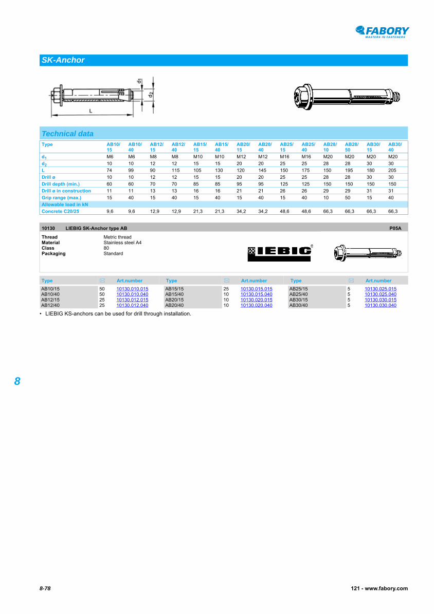
8-78 121 - www.fabory.com
8
LIEBIG SK-Anchor type AB10130
LIEBIG SK-Anchor type AB10130
• LIEBIG KS-anchors can be used for drill through installation.
SK-Anchor
Technical dataType AB10/
15AB10/40
AB12/15
AB12/40
AB15/15
AB15/40
AB20/15
AB20/40
AB25/15
AB25/40
AB28/10
AB28/50
AB30/15
AB30/40
d1 M6 M6 M8 M8 M10 M10 M12 M12 M16 M16 M20 M20 M20 M20
d2 10 10 12 12 15 15 20 20 25 25 28 28 30 30
L 74 99 90 115 105 130 120 145 150 175 150 195 180 205
Drill ø 10 10 12 12 15 15 20 20 25 25 28 28 30 30
Drill depth (min.) 60 60 70 70 85 85 95 95 125 125 150 150 150 150
Drill ø in construction 11 11 13 13 16 16 21 21 26 26 29 29 31 31
Grip range (max.) 15 40 15 40 15 40 15 40 15 40 10 50 15 40
Allowable load in kN
Concrete C20/25 9,6 9,6 12,9 12,9 21,3 21,3 34,2 34,2 48,6 48,6 66,3 66,3 66,3 66,3
10130 LIEBIG SK-Anchor type AB P05A
Thread Metric threadMaterial Stainless steel A4Class 80Packaging Standard
Type Art.number Type Art.number Type Art.number
AB10/15 50 10130.010.015AB10/40 50 10130.010.040AB12/15 25 10130.012.015AB12/40 25 10130.012.040
AB15/15 25 10130.015.015AB15/40 10 10130.015.040AB20/15 10 10130.020.015AB20/40 10 10130.020.040
AB25/15 5 10130.025.015AB25/40 5 10130.025.040AB30/15 5 10130.030.015AB30/40 5 10130.030.040

8-79121 - www.fabory.com
8
• tfix (max.) = Grip range (max.)• Concrete C20/25; recommended load for non-cracked concrete.• For VinyMaxx and AcryMaxx resins.
MAXXFAST Chemical fixing threaded rod30585
MAXXFAST Chemical fixing threaded rod
Chemical fixing threaded rod
Technical dataType M8x110 M10x130 M12x160 M12x220 M16x190 M16x220 M20x260
d M8 M10 M12 M12 M16 M16 M20
L 110 130 160 220 190 220 260
tfix (max.) 17 28 36 85 42 67 65
Drill ø 10 12 14 14 18 18 24
Allowable load in kN
Concrete C20/25 5,9 8,1 11,4 11,4 20 20 30,9
30585 MAXXFAST Chemical fixing threaded rod MF50
Thread Metric threadMaterial Steel Surface treatment Zinc platedPackaging Standard
Type Art.number Type Art.number Type Art.number
M8X110 10 30585.080.110M10X130 10 30585.100.130M12X160 10 30585.120.160
M12X220 10 30585.120.220
M16X190 10 30585.160.190
M16X220 10 30585.160.220
M20X260 6 30585.200.260
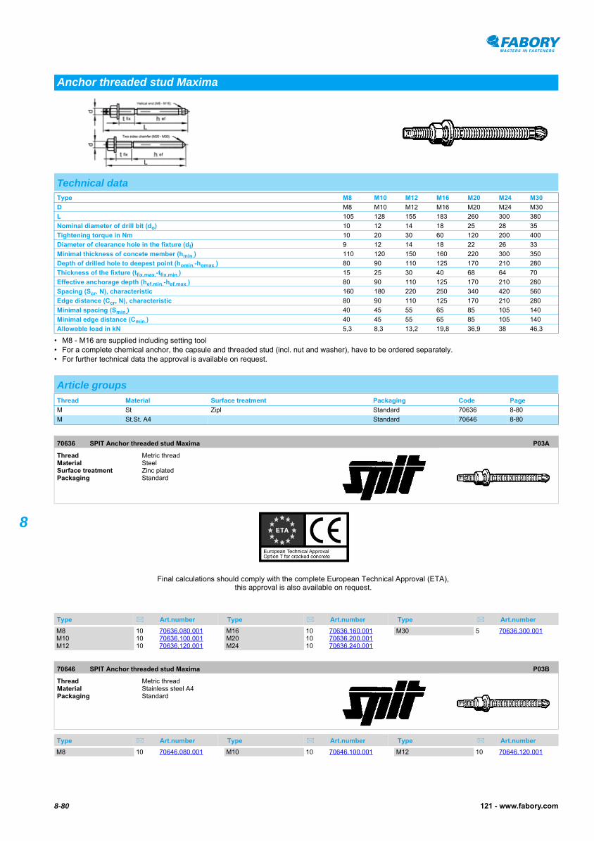
8-80 121 - www.fabory.com
8
• M8 - M16 are supplied including setting tool• For a complete chemical anchor, the capsule and threaded stud (incl. nut and washer), have to be ordered separately.• For further technical data the approval is available on request.
SPIT Anchor threaded stud Maxima70636
SPIT Anchor threaded stud Maxima70646
Anchor threaded stud Maxima
Technical dataType M8 M10 M12 M16 M20 M24 M30
D M8 M10 M12 M16 M20 M24 M30
L 105 128 155 183 260 300 380
Nominal diameter of drill bit (do) 10 12 14 18 25 28 35
Tightening torque in Nm 10 20 30 60 120 200 400
Diameter of clearance hole in the fixture (df) 9 12 14 18 22 26 33
Minimal thickness of concete member (hmin.) 110 120 150 160 220 300 350
Depth of drilled hole to deepest point (homin.-homax.) 80 90 110 125 170 210 280
Thickness of the fixture (tfix.max.-tfix.min.) 15 25 30 40 68 64 70
Effective anchorage depth (hef.min.-hef.max.) 80 90 110 125 170 210 280
Spacing (Scr, N), characteristic 160 180 220 250 340 420 560
Edge distance (Ccr, N), characteristic 80 90 110 125 170 210 280
Minimal spacing (Smin.) 40 45 55 65 85 105 140
Minimal edge distance (Cmin.) 40 45 55 65 85 105 140
Allowable load in kN 5,3 8,3 13,2 19,8 36,9 38 46,3
Article groupsThread Material Surface treatment Packaging Code Page
M St Zipl Standard 70636 8-80
M St.St. A4 Standard 70646 8-80
70636 SPIT Anchor threaded stud Maxima P03A
Thread Metric threadMaterial Steel Surface treatment Zinc platedPackaging Standard
Type Art.number Type Art.number Type Art.number
Final calculations should comply with the complete European Technical Approval (ETA), this approval is also available on request.
M8 10 70636.080.001M10 10 70636.100.001M12 10 70636.120.001
M16 10 70636.160.001M20 10 70636.200.001M24 10 70636.240.001
M30 5 70636.300.001
70646 SPIT Anchor threaded stud Maxima P03B
Thread Metric threadMaterial Stainless steel A4Packaging Standard
Type Art.number Type Art.number Type Art.number
M8 10 70646.080.001 M10 10 70646.100.001 M12 10 70646.120.001
70646 SPIT Anchor threaded stud Maxima Type Art.number Type Art.number Type Art.number
8-81121 - www.fabory.com
8
SPIT Anchor threaded stud Maxima
M16 10 70646.160.001M20 10 70646.200.001
M24 10 70646.240.001M30 5 70646.300.001

8-82 121 - www.fabory.com
8
• tfix (max.) = Grip range (max.)• Concrete C20/25 to C50/65; recommended load for non-cracked concrete.
FISCHER Chemical fixing threaded rod type RG M63187
FISCHER Chemical fixing threaded rod type RG M63187
FISCHER Chemical fixing threaded rod type RG M63188
FISCHER Chemical fixing threaded rod type RG M
Chemical fixing threaded rod
Technical dataType M8x
110M10x130
M10x165
M10x190
M12x160
M12x220
M12x250
M12x300
M16x190
M16x250
M16x300
M20x260
M20x350
M24x300
M30x380
d M8 M10 M10 M10 M12 M12 M12 M12 M16 M16 M16 M20 M20 M24 M30
L 110 130 165 190 160 220 250 300 190 250 300 260 350 300 380
tfix (max.) 13 20 57 82 25 90 120 170 35 98 148 65 155 65 65
Allowable load in kN
Concrete 6,3 7,9 7,9 7,9 11,9 11,9 11,9 11,9 19,8 19,8 19,8 29,8 29,8 37,7 67,5
Article groupsThread Material Surface treatment Packaging Code Page
M St Zipl Standard 63187 8-82
M St.St. A4 Standard 63188 8-82
63187 FISCHER Chemical fixing threaded rod type RG M N03B
Thread Metric threadMaterial Steel Surface treatment Zinc platedPackaging Standard
Type Art.number Type Art.number Type Art.number
M8X110 10 63187.080.110M10X130 10 63187.100.130M10X165 10 63187.100.165M10X190 10 63187.100.190
M12X160 10 63187.120.160M12X220 10 63187.120.220
M12X250 10 63187.120.250M12X300 10 63187.120.300
M16X190 10 63187.160.190M16X250 10 63187.160.250M16X300 10 63187.160.300
M20X260 10 63187.200.260M20X350 10 63187.200.350
M24X300 10 63187.240.300M30X380 5 63187.300.380
63188 FISCHER Chemical fixing threaded rod type RG M N03B
Thread Metric threadMaterial Stainless steel A4Packaging Standard
Type Art.number Type Art.number Type Art.number
M8X110 10 63188.080.110M10X130 10 63188.100.130M10X165 10 63188.100.165
M12X160 10 63188.120.160M16X190 10 63188.160.190
M20X260 10 63188.200.260M24X300 10 63188.240.300
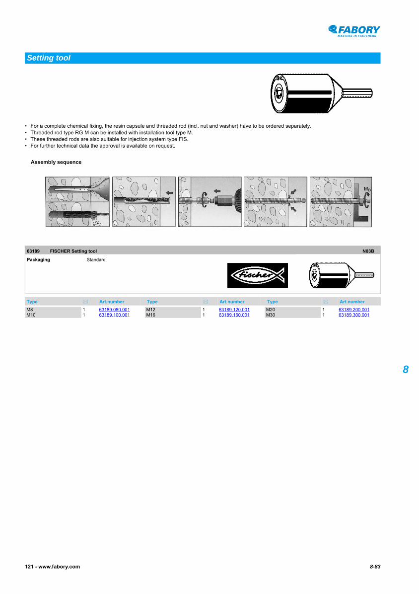
8-83121 - www.fabory.com
8
• For a complete chemical fixing, the resin capsule and threaded rod (incl. nut and washer) have to be ordered separately.• Threaded rod type RG M can be installed with installation tool type M.• These threaded rods are also suitable for injection system type FIS.• For further technical data the approval is available on request.
FISCHER Setting tool63189
FISCHER Setting tool
Setting tool
63189 FISCHER Setting tool N03B
Packaging Standard
Type Art.number Type Art.number Type Art.number
Assembly sequence
M8 1 63189.080.001M10 1 63189.100.001
M12 1 63189.120.001M16 1 63189.160.001
M20 1 63189.200.001M30 1 63189.300.001

8-84 121 - www.fabory.com
8
• For a complete chemical anchor, the capsule and threaded stud (incl. nut and washer), have to be ordered separately.
SPIT Chemical fixing resin capsule type EA
Chemical anchor capsule
Technical dataType d L Drill ø Drill depth (min.)
M8 9 80 10 80
M10 10,5 85 12 90
M12 12,5 95 14 110
M16 16,5 95 18 125
M20 23 160 25 170
M24 23 190 28 210
M30 27,5 260 35 280
Article groupsMaterial Packaging Code Page
Glass Standard 70615 8-84
Glass Standard 63186 8-85
70615 SPIT Chemical fixing resin capsule type EA P03A
Material Glass Packaging Standard
Type Art.number Type Art.number Type Art.number
Final calculations should comply with the complete European Technical Approval (ETA), this approval is also available on request.
M8 10 70615.080.001M10 10 70615.100.001M12 10 70615.120.001
M16 10 70615.160.001M20 10 70615.200.001M24 10 70615.240.001
M30 5 70615.300.001
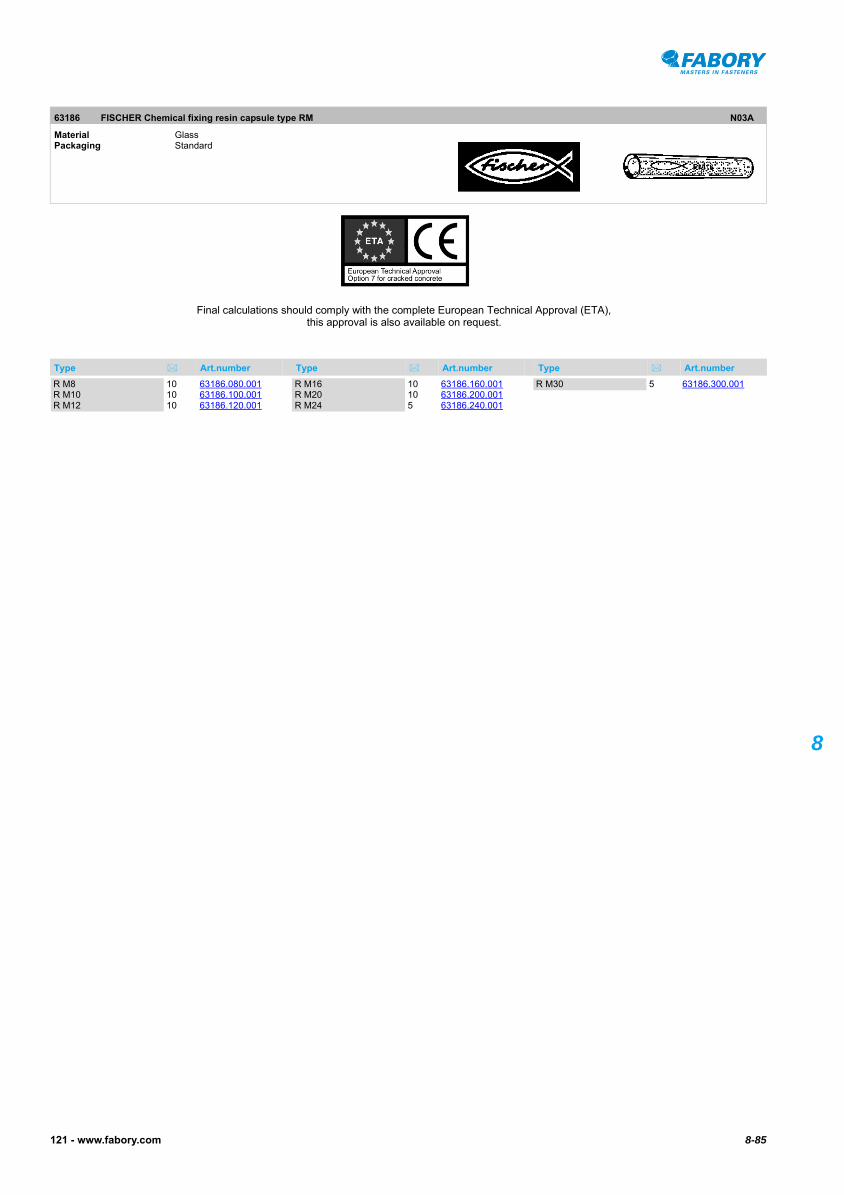
8-85121 - www.fabory.com
8
FISCHER Chemical fixing resin capsule type RM
63186 FISCHER Chemical fixing resin capsule type RM N03A
Material Glass Packaging Standard
Type Art.number Type Art.number Type Art.number
Final calculations should comply with the complete European Technical Approval (ETA), this approval is also available on request.
R M8 10 63186.080.001R M10 10 63186.100.001R M12 10 63186.120.001
R M16 10 63186.160.001R M20 10 63186.200.001R M24 5 63186.240.001
R M30 5 63186.300.001

8-86 121 - www.fabory.com
8
MAXXFAST Injection cartridge30580
MAXXFAST Injection cartridge30580
MAXXFAST Injection cartridge30581
MAXXFAST Injection cartridge
Injection cartridge
Assembly data
Article groupsPackaging Code Page
AcryMaxx Standard 30580 8-86
VinyMaxx Standard 30581 8-86
FIS VS Standard 63252 8-87
FIS V Standard 63051 8-87
FIS VS Standard 63060 8-87
30580 MAXXFAST Injection cartridge MF50
Packaging Standard
Type Art.number
AcryMaxx 1 30580.000.310 • High performance two component styrene free resin for anchoring threaded rod and internally threaded sockets in concrete.
• European Technical Approval and CE marking.• Resistant to extreme temperatures (from -40oC to +80oC) after polymerisation.• 310 ml.
30581 MAXXFAST Injection cartridge MF50
Packaging Standard
Type Art.number
VinyMaxx 1 30581.000.310 • Styrene free high performance resin for solid and hollow substrates.• 310 ml.
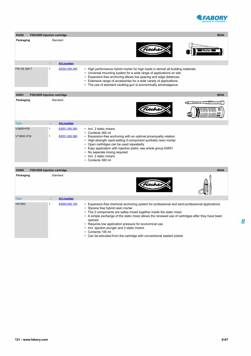
8-87121 - www.fabory.com
8
FISCHER Injection cartridge63252
FISCHER Injection cartridge63252
FISCHER Injection cartridge63051
FISCHER Injection cartridge63051
FISCHER Injection cartridge63060
FISCHER Injection cartridge
63252 FISCHER Injection cartridge N03A
Packaging Standard
Art.number
FIS VS 300 T 1 63252.000.300 • High performance hybrid mortar for high loads in almost all building materials.• Universal mounting system for a wide range of applications on site.• Expansion-free anchoring allows low spacing and edge distances.• Extensive range of accessories for a wide variety of applications.• The use of standard caulking gun is economically advantageous.
63051 FISCHER Injection cartridge N03A
Packaging Standard
Type Art.number
V360S=FIS 1 63051.000.360 • Incl. 2 static mixers• Contents 360 ml
VT380C=FIS 1 63051.000.380 • Expansion-free anchoring with an optimal price/quality relation• High-strength rapid-setting 2-component synthetic resin mortar• Open cartridges can be used repeatedly• Easy application with injection pistol, see article group 63691• No seperate mixing required• Incl. 2 static mixers• Contents 380 ml
63060 FISCHER Injection cartridge N03A
Packaging Standard
Type Art.number
VS150C 1 63060.000.150 • Expansion-free chemical anchoring system for professional and semi-professional applications• Styrene free hybrid resin mortar• The 2 components are safely mixed together inside the static mixer• A simple exchange of the static mixer allows the renewed use of cartridges after they have been
opened• Requires low application pressure for economical use• Incl. ejection plunger and 2 static mixers• Contents 145 ml• Can be extruded from the cartridge with conventional sealant pistols

8-88 121 - www.fabory.com
8
MAXXFAST Injection tool30595
MAXXFAST Injection tool30595
FISCHER Injection tool63691
FISCHER Injection tool63691
FISCHER Injection tool63247
FISCHER Injection tool63247
FISCHER Injection tool63242
FISCHER Injection tool63242
FISCHER Injection tool63243
FISCHER Injection tool
Injection tool
30595 MAXXFAST Injection tool MF50
Packaging Standard
Type Art.number
Gun 1 30595.000.100 • For VinyMaxx and AcryMaxx resins.
63691 FISCHER Injection tool N03C
Packaging Standard
Type Art.number
K FIS VT 1 63691.100.020 • Suitable for injection cartridge type FIS VT 380 C
63247 FISCHER Injection tool N03A
Packaging Standard
Type Art.number
Static mixer 10 63247.000.005 • Suitable for injection cartridge type FIS V• Plastic
63242 FISCHER Injection tool N03A
Packaging Standard
Type Art.number
FIS AK 1 63242.000.005 • Suitable for injection cartridge type FIS V 360 S and FIS VS 150 C.
63243 FISCHER Injection tool N03A
Packaging Standard
Type Art.number Type Art.number Type Art.number
14/20 MM 1 63243.014.020

8-89121 - www.fabory.com
8
Anchoring accessories
Technical dataType 12x50 15x85 15x130 20x85
do 12 15 15 20
L 50 85 130 85
Drill ø 12 15 15 20
Drill depth (min.) 60 95 140 95
Assembly depth (min.) 50 85 130 85
Threaded rod size M6 M8-M10-M12 M8-M10-M12 M12-M16
30596 MAXXFAST Anchoring accessories MF50
Packaging Standard
Type Art.number
BLOW PUMP 1 30596.000.001 • Plastic
MIXING NOZZLE 5 30596.000.005 • Plastic
BRUSH WHITE 1 30596.008.012 • 8-12mm
BRUSH BLUE 1 30596.010.018 • 10-18mm
BRUSH RED 1 30596.012.028 • 12-28mm
ANCHOR SLEEVE 10 30596.012.050 • Plastic Nylon (polyamide)• 12x50
ANCHOR SLEEVE 10 30596.015.085 • Plastic Nylon (polyamide)• 15x85

30596 MAXXFAST Anchoring accessories
Type Art.number Type Art.number Type Art.number
8-90 121 - www.fabory.com
8
MAXXFAST Anchoring accessories
ANCHOR SLEEVE 10 30596.015.130 • Plastic Nylon (polyamide)• 15x130
ANCHOR SLEEVE 10 30596.020.085 • Plastic Nylon (polyamide)• 20x85

8-91121 - www.fabory.com
8FISCHER Injection system injection anchor sleeve type FIS H N63052
FISCHER Injection system injection anchor sleeve type FIS H N63052
FISCHER Injection system injection anchor sleeve type FIS H L63050
FISCHER Injection system injection anchor sleeve type FIS H L
Injection system injection anchor sleeve
Technical dataType FIS H16 x 85N FIS H18 x 85N FIS H20 x 85N FIS H12 X 1000 FIS H16 X 1000 FIS H22 X 1000
d 16 18 20 12 16 22
L 85 85 85 1000 1000 1000
Drill ø 16 18 20 12 16 22
Drill depth (min.) 95 95 95 - - -
Assembly depth (min.) 85 85 85 - - -
Threaded rod size M8 M10 M12 M6-M8 M10-M12 M12-M16
Assembly sequence
Article groupsMaterial Surface treatment Packaging Code Page
Plastic PA Standard 63052 8-91
St Zipl Standard 63050 8-91
63052 FISCHER Injection system injection anchor sleeve type FIS H N N03A
Material Plastic Polyamide (nylon)Packaging Standard
Type Art.number Type Art.number Type Art.number
FIS16X85MM 20 63052.160.085 FIS18X85MM 20 63052.180.085 FIS20X85MM 20 63052.200.085
63050 FISCHER Injection system injection anchor sleeve type FIS H L N03A
Material Steel Surface treatment Zinc platedPackaging Standard
d x L Art.number d x L Art.number d x L Art.number
12X1000MM 10 63050.120.001 16X1000MM 10 63050.160.001 22X1000MM 6 63050.220.001
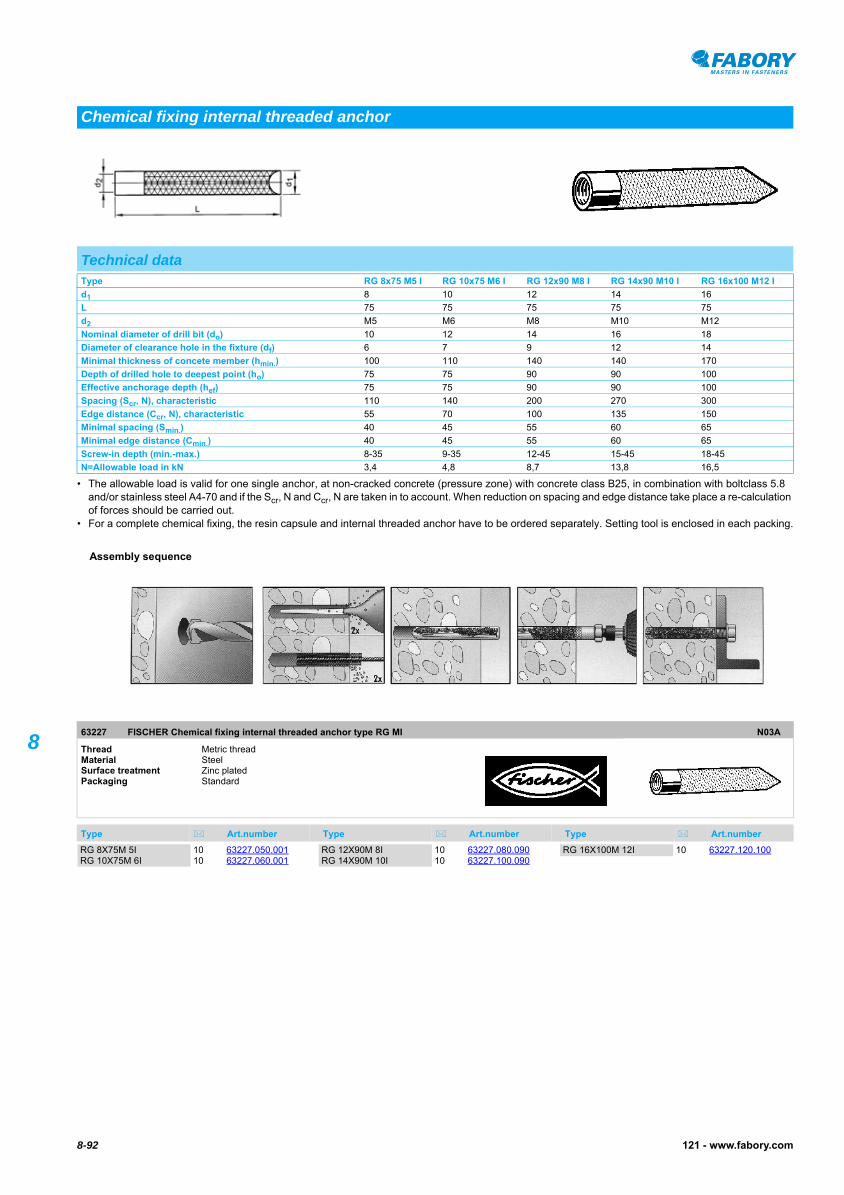
8-92 121 - www.fabory.com
8
• The allowable load is valid for one single anchor, at non-cracked concrete (pressure zone) with concrete class B25, in combination with boltclass 5.8 and/or stainless steel A4-70 and if the Scr, N and Ccr, N are taken in to account. When reduction on spacing and edge distance take place a re-calculation of forces should be carried out.
• For a complete chemical fixing, the resin capsule and internal threaded anchor have to be ordered separately. Setting tool is enclosed in each packing.
FISCHER Chemical fixing internal threaded anchor type RG MI63227
FISCHER Chemical fixing internal threaded anchor type RG MI
Chemical fixing internal threaded anchor
Technical dataType RG 8x75 M5 I RG 10x75 M6 I RG 12x90 M8 I RG 14x90 M10 I RG 16x100 M12 I
d1 8 10 12 14 16
L 75 75 75 75 75
d2 M5 M6 M8 M10 M12
Nominal diameter of drill bit (do) 10 12 14 16 18
Diameter of clearance hole in the fixture (df) 6 7 9 12 14
Minimal thickness of concete member (hmin.) 100 110 140 140 170
Depth of drilled hole to deepest point (ho) 75 75 90 90 100
Effective anchorage depth (hef) 75 75 90 90 100
Spacing (Scr, N), characteristic 110 140 200 270 300
Edge distance (Ccr, N), characteristic 55 70 100 135 150
Minimal spacing (Smin.) 40 45 55 60 65
Minimal edge distance (Cmin.) 40 45 55 60 65
Screw-in depth (min.-max.) 8-35 9-35 12-45 15-45 18-45
N=Allowable load in kN 3,4 4,8 8,7 13,8 16,5
63227 FISCHER Chemical fixing internal threaded anchor type RG MI N03A
Thread Metric threadMaterial Steel Surface treatment Zinc platedPackaging Standard
Type Art.number Type Art.number Type Art.number
Assembly sequence
RG 8X75M 5I 10 63227.050.001RG 10X75M 6I 10 63227.060.001
RG 12X90M 8I 10 63227.080.090RG 14X90M 10I 10 63227.100.090
RG 16X100M 12I 10 63227.120.100

8-93121 - www.fabory.com
8
Masonry bolt type A20710
Masonry bolt type A
Masonry bolt type A
DIN 529 ANEN 2328 A
Technical datad P a b c
M12 1,75 36 30 65
M16 2 48 40 85
M20 2,5 60 50 105
M24 3 75 60 125
M30 3,5 95 75 155
20710 Masonry bolt type A G06D
Thread Metric threadMaterial Steel Class 4.6Packaging Standard
d x L Art.number d x L Art.number d x L Art.number
M12X160 25 20710.120.160M12X200 25 20710.120.200M12X250 25 20710.120.250
M16X160 10 20710.160.160M16X200 10 20710.160.200M16X250 10 20710.160.250M16X320 10 20710.160.320M16X400 10 20710.160.400
M20X200 5 20710.200.200M20X250 5 20710.200.250M20X320 5 20710.200.320M20X400 5 20710.200.400M20X500 5 20710.200.500
M24X250 3 20710.240.250M24X320 3 20710.240.320
M24X400 3 20710.240.400M24X500 3 20710.240.500
M30X400 2 20710.300.400M30X500 2 20710.300.500M30X630 2 20710.300.630

8-94 121 - www.fabory.com
8
Masonry bolt type E20750
Masonry bolt type E
Masonry bolt type E
DIN 529 ENEN 2328 E
Technical datad P a b c
M10 1,5 20 25 55
M12 1,75 24 30 70
M16 2 32 40 90
M20 2,5 40 50 100
M24 3 48 60 135
M30 3,5 60 75 150
20750 Masonry bolt type E G06D
Thread Metric threadMaterial Steel Class 3.6Surface treatment Zinc platedPackaging Standard
d x L Art.number d x L Art.number d x L Art.number
M10X125 25 20750.100.125M12X125 25 20750.120.125M16X160 10 20750.160.160M20X200 5 20750.200.200M20X320 5 20750.200.320
M24X250 3 20750.240.250M24X320 3 20750.240.320
M30X320 2 20750.300.320
M30X630 2 20750.300.630

8-95121 - www.fabory.com
8
• Steel with a tensile strength of min. 400 N/mm2 and a lower yield stress of min. 240 N/mm2.
Hook anchor with 50mm hook20610
Hook anchor with 50mm hook20610
Hook anchor with 50mm hook20630
Hook anchor with 50mm hook20630
Hook anchor with 50mm hook oversized thread20650
Hook anchor
Technical datad P a
M10 2 150
M12 1,75 150
M16 2 150
M20 2,5 150
M24 3 150
M30 3,5 150
Article groupsThread Material Surface treatment Packaging Code Page
M St 50mm hook Standard 20610 8-95
M St Zipl 50mm hook Standard 20630 8-95
M St Hot d.g. 50mm hook Standard 20650 8-95
M St 100mm hook Standard 20620 8-96
M St Zipl 100mm hook Standard 20640 8-96
M St Hot d.g. 100mm hook Standard 20660 8-96
20610 Hook anchor with 50mm hook G06D
Thread Metric threadMaterial Steel Packaging Standard
d x L Art.number d x L Art.number d x L Art.number
M10X200 25 20610.100.200M10X300 25 20610.100.300
M12X300 25 20610.120.300M12X400 25 20610.120.400
M16X250 10 20610.160.250M16X300 10 20610.160.300M16X350 10 20610.160.350M16X400 10 20610.160.400
M16X450 10 20610.160.450
M20X400 5 20610.200.400
20630 Hook anchor with 50mm hook G06D
Thread Metric threadMaterial Steel Surface treatment Zinc platedPackaging Standard
d x L Art.number d x L Art.number d x L Art.number
M10X200 25 20630.100.200M12X250 25 20630.120.250M16X250 10 20630.160.250
M16X300 10 20630.160.300M16X350 10 20630.160.350M16X400 10 20630.160.400
M16X450 10 20630.160.450M16X500 10 20630.160.500
20650 Hook anchor with 50mm hook oversized thread G06D
Thread Metric threadMaterial Steel Surface treatment Hot dip galvanizedPackaging Standard
d x L Art.number d x L Art.number d x L Art.number
M12X300 25 20650.120.300M12X400 25 20650.120.400 M16X300 10 20650.160.300
M16X400 10 20650.160.400
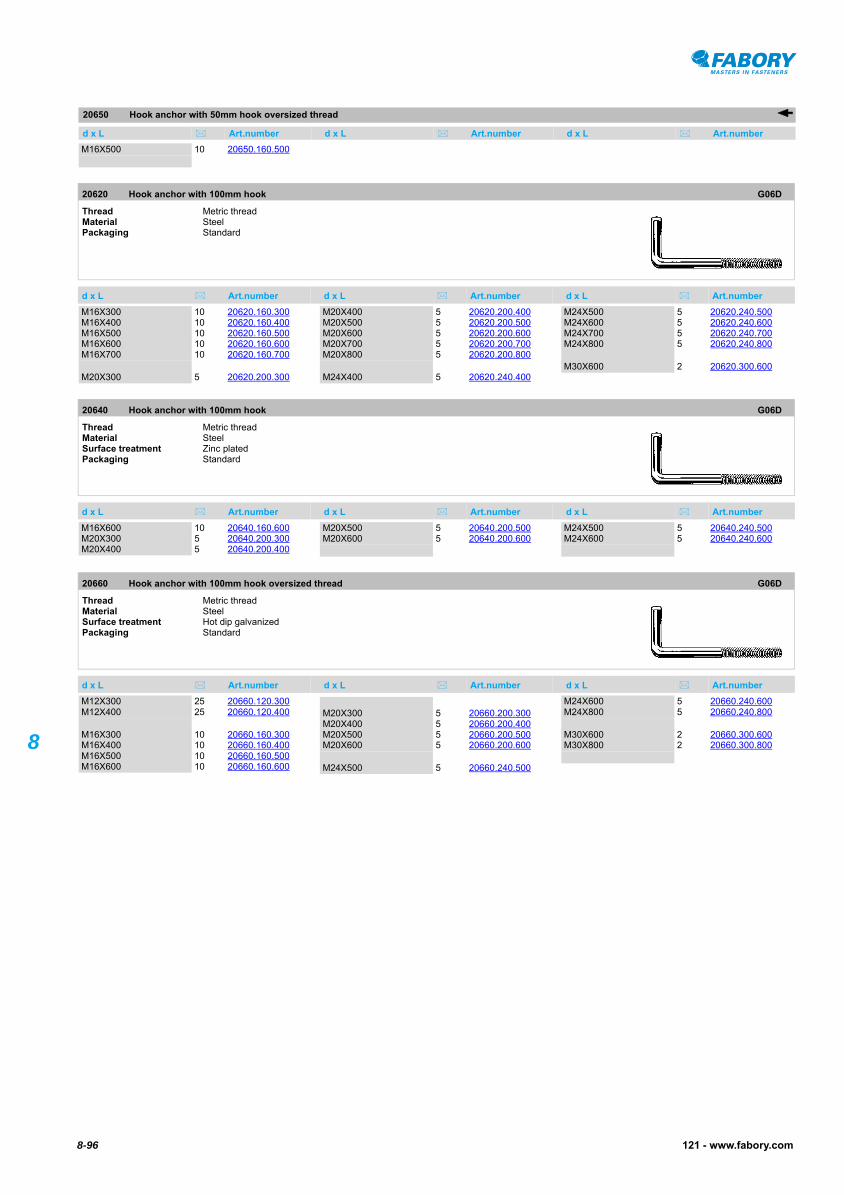
20650 Hook anchor with 50mm hook oversized thread
d x L Art.number d x L Art.number d x L Art.number
8-96 121 - www.fabory.com
8
Hook anchor with 50mm hook oversized thread20650
Hook anchor with 100mm hook20620
Hook anchor with 100mm hook20620
Hook anchor with 100mm hook20640
Hook anchor with 100mm hook20640
Hook anchor with 100mm hook oversized thread20660
Hook anchor with 100mm hook oversized thread
M16X500 10 20650.160.500
20620 Hook anchor with 100mm hook G06D
Thread Metric threadMaterial Steel Packaging Standard
d x L Art.number d x L Art.number d x L Art.number
M16X300 10 20620.160.300M16X400 10 20620.160.400M16X500 10 20620.160.500M16X600 10 20620.160.600M16X700 10 20620.160.700
M20X300 5 20620.200.300
M20X400 5 20620.200.400M20X500 5 20620.200.500M20X600 5 20620.200.600M20X700 5 20620.200.700M20X800 5 20620.200.800
M24X400 5 20620.240.400
M24X500 5 20620.240.500M24X600 5 20620.240.600M24X700 5 20620.240.700M24X800 5 20620.240.800
M30X600 2 20620.300.600
20640 Hook anchor with 100mm hook G06D
Thread Metric threadMaterial Steel Surface treatment Zinc platedPackaging Standard
d x L Art.number d x L Art.number d x L Art.number
M16X600 10 20640.160.600M20X300 5 20640.200.300M20X400 5 20640.200.400
M20X500 5 20640.200.500M20X600 5 20640.200.600
M24X500 5 20640.240.500M24X600 5 20640.240.600
20660 Hook anchor with 100mm hook oversized thread G06D
Thread Metric threadMaterial Steel Surface treatment Hot dip galvanizedPackaging Standard
d x L Art.number d x L Art.number d x L Art.number
M12X300 25 20660.120.300M12X400 25 20660.120.400
M16X300 10 20660.160.300M16X400 10 20660.160.400M16X500 10 20660.160.500M16X600 10 20660.160.600
M20X300 5 20660.200.300M20X400 5 20660.200.400M20X500 5 20660.200.500M20X600 5 20660.200.600
M24X500 5 20660.240.500
M24X600 5 20660.240.600M24X800 5 20660.240.800
M30X600 2 20660.300.600M30X800 2 20660.300.800
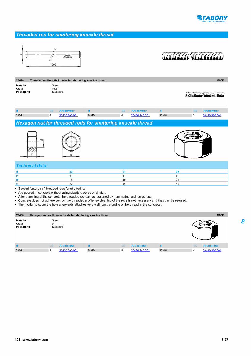
8-97121 - www.fabory.com
8
Threaded rod length 1 meter for shuttering knuckle thread20420
Threaded rod length 1 meter for shuttering knuckle thread
• Special features of threaded rods for shuttering:• Are poured in concrete without using plastic sleeves or similar.• After starching of the concrete the threaded rod can be loosened by hammering and turned out.• Concrete does not adhere well on the threaded profile, so cleaning of the rods is not necessary and they can be re-used.• The mortar to cover the hole afterwards attaches very well (contra-profile of the thread in the concrete).
Hexagon nut for threaded rods for shuttering knuckle thread20430
Hexagon nut for threaded rods for shuttering knuckle thread
Threaded rod for shuttering knuckle thread
20420 Threaded rod length 1 meter for shuttering knuckle thread G05B
Material Steel Class ≥4.8Packaging Standard
d Art.number d Art.number d Art.number
20MM 4 20420.200.001 24MM 4 20420.240.001 30MM 2 20420.300.001
Hexagon nut for threaded rods for shuttering knuckle thread
Technical datad 20 24 30
P 5 5 5
m 16 19 24
s 30 36 46
20430 Hexagon nut for threaded rods for shuttering knuckle thread G05B
Material Steel Class 5Packaging Standard
d Art.number d Art.number d Art.number
20MM 8 20430.200.001 24MM 8 20430.240.001 30MM 4 20430.300.001
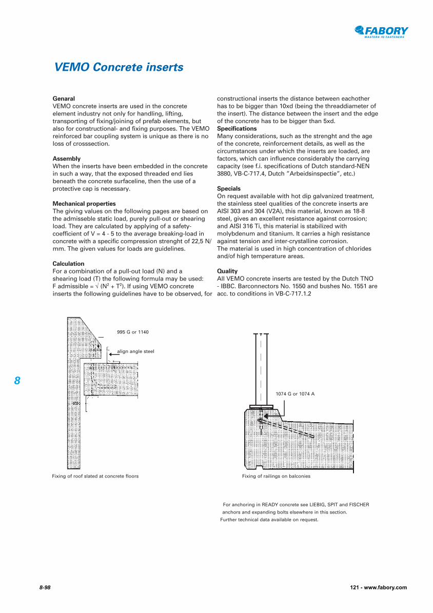
Genaral
VEMO concrete inserts are used in the concrete element industry not only for handling, lifting, transporting of fixing/joining of prefab elements, but also for constructional- and fixing purposes. The VEMO reinforced bar coupling system is unique as there is no loss of crosssection.
Assembly
When the inserts have been embedded in the concrete in such a way, that the exposed threaded end lies beneath the concrete surfaceline, then the use of a protective cap is necessary.
Mechanical properties
The giving values on the following pages are based on the admisseble static load, purely pull-out or shearing load. They are calculated by applying of a safety-coefficient of V = 4 - 5 to the average breaking-load in concrete with a specific compression strenght of 22,5 N/mm. The given values for loads are guidelines.
Calculation
For a combination of a pull-out load (N) and a shearing load (T) the following formula may be used: F admissible = √ (N2 + T2). If using VEMO concrete inserts the following guidelines have to be observed, for
constructional inserts the distance between eachother has to be bigger than 10xd (being the threaddiameter of the insert). The distance between the insert and the edge of the concrete has to be bigger than 5xd.Specifications
Many considerations, such as the strenght and the age of the concrete, reinforcement details, as well as the circumstances under which the inserts are loaded, are factors, which can influence considerably the carrying capacity (see f.i. specifications of Dutch standard-NEN 3880, VB-C-717.4, Dutch ”Arbeidsinspectie”, etc.)
Specials
On request available with hot dip galvanized treatment, the stainless steel qualities of the concrete inserts are AISI 303 and 304 (V2A), this material, known as 18-8 steel, gives an excellent resistance against corrosion; and AISI 316 Ti, this material is stabilized with molybdenum and titanium. It carries a high resistance against tension and inter-crystalline corrosion. The material is used in high concentration of chloridesand/of high temperature areas.
Quality
All VEMO concrete inserts are tested by the Dutch TNO - IBBC. Barconnectors No. 1550 and bushes No. 1551 are acc. to conditions in VB-C-717.1.2
VEMO Concrete inserts
For anchoring in READY concrete see LIEBIG, SPIT and FISCHER
anchors and expanding bolts elsewhere in this section.
Further technical data available on request.
995 G or 1140
align angle steel
1074 G or 1074 A
Fixing of roof slated at concrete floors Fixing of railings on balconies
8-98 121 - www.fabory.com
8
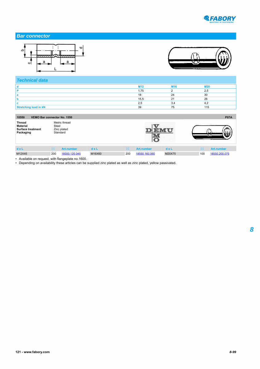
8-99121 - www.fabory.com
8
VEMO Bar connector No. 155018550
VEMO Bar connector No. 155018550
• Available on request, with flangeplate no.1600.• Depending on availability these articles can be supplied zinc plated as well as zinc plated, yellow passivated.
Bar connector
Technical datad M12 M16 M20
P 1,75 2 2,5
a 18 24 30
b 15,5 21 26
c 2,5 3,4 4,2
Stretching load in kN 39 75 115
18550 VEMO Bar connector No. 1550 P07A
Thread Metric threadMaterial Steel Surface treatment Zinc platedPackaging Standard
d x L Art.number d x L Art.number d x L Art.number
M12X45 200 18550.120.045 M16X60 200 18550.160.060 M20X75 100 18550.200.075

8-100 121 - www.fabory.com
8
• Pull-out force in kN.• It is advised to take a safety factor 4.
VEMO Tube insert No. 995 G18040
VEMO Tube insert No. 995 G18040
• Depending on availability these articles can be supplied zinc plated as well as zinc plated, yellow passivated.
Tube insert No. 995G
Technical datad M6 M8 M10 M12 M16 M16 M20 M24 M30
L 40 40 50 60 70 100 100 120 150
a 20 20 20 25 25 32 40 50 70
b 8,5 10,5 13,5 17 21,3 21,3 26,9 33,7 42
c 1 1 1,5 2 3,2 3,2 3,2 4 4
e 6 8 10 12 16 16 20 24 30
f 12,5 16 20 25 30 30 39 48 64
g 6,2 8,1 6,2 7,2 9,2 9,2 12,2 14,2 15,2
h 7 8 12 15 17 22 22 25 25
Pull-out force in kN
Concrete 6 10 14 20 28 40 50 72 110
18040 VEMO Tube insert No. 995 G P07A
Thread Metric threadMaterial Steel Surface treatment Zinc platedPackaging Standard
d x L Art.number d x L Art.number d x L Art.number
M6X40 500 18040.060.040M8X50 500 18040.080.050M10X50 500 18040.100.050M12X60 400 18040.120.060
M16X70 200 18040.160.070M16X100 100 18040.160.100
M20X100 100 18040.200.100
M24X120 50 18040.240.120M30X150 25 18040.300.150

8-101121 - www.fabory.com
8
• Pull-out force in kN.• It is advised to take a safety factor 4.
VEMO Insert with nailing plate No. 103618060
VEMO Insert with nailing plate No. 103618060
• Depending on availability these articles can be supplied zinc plated as well as zinc plated, yellow passivated.
Insert with nailing plate No. 1036
Technical datad M10 M12 M16 M20 M24
a 30 40 32 50 40
b 13,5 17 21,3 26,9 33,7
c 1,5 2 2,6 2,6 4
e 10 12 16 20 24
f 20 25 31 39 48
k 34 40 44 48 57
m 1 1 1,5 1,5 1,5
Pull-out force in kN
Concrete 16 24 40 50 64
18060 VEMO Insert with nailing plate No. 1036 P07A
Thread Metric threadMaterial Steel Surface treatment Zinc platedPackaging Standard
d x L Art.number d x L Art.number d x L Art.number
M10X60 200 18060.100.060M12X70 200 18060.120.070
M16X100 100 18060.160.100M20X100 100 18060.200.100

8-102 121 - www.fabory.com
8
• Pull-out force in kN.• It is advised to take a safety factor 4.
VEMO Insert with nailing No. 113018140
VEMO Insert with nailing No. 113018140
• Depending on availability these articles can be supplied zinc plated as well as zinc plated, yellow passivated.
Insert with nailing plate No. 1130
Technical datad M10 M12 M16 M20
a 35 40 32 40
b 13,5 17 21,3 26,9
c 1,5 2 2,6 2,6
e 10 12 16 20
j 25 30 35 35
k 34 40 44 48
m 1 1 1,5 1,5
Pull-out force in kN
Concrete 24 32 52 64
18140 VEMO Insert with nailing No. 1130 P07A
Thread Metric threadMaterial Steel Surface treatment Zinc platedPackaging Standard
d x L Art.number d x L Art.number d x L Art.number
M10X60 400 18140.100.060 M12X70 200 18140.120.070 M16X100 100 18140.160.100

8-103121 - www.fabory.com
8
VEMO Bush No. 155118570
VEMO Bush No. 155118570
• Depending on availability these articles can be supplied zinc plated as well as zinc plated, yellow passivated.
VEMO Pipe plug No. 224418600
VEMO Pipe plug No. 2244
Bush
Technical datad P b Stretching load in kN
M6 1 10 13
M8 1,25 12 16
M10 1,5 13 14
M12 1,75 15,5 39
M16 2 21 75
M20 2,5 26 115
M24 3 32 181
M30 3,5 40 284
18570 VEMO Bush No. 1551 P07A
Thread Metric threadMaterial Steel Surface treatment Zinc platedPackaging Standard
d x L Art.number d x L Art.number d x L Art.number
M6X15 200 18570.060.015M8X20 200 18570.080.020M10X25 200 18570.100.025
M12X35 200 18570.120.035M16X45 200 18570.160.045M20X55 100 18570.200.055
M24X70 50 18570.240.070M30X90 25 18570.300.090
Pipe plug
18600 VEMO Pipe plug No. 2244 P07A
Material Plastic PolyethylenePackaging Standard
d = For nom. size Art.number d = For nom. size Art.number d = For nom. size Art.number
M6-RED 100 18600.060.001M8-RED 100 18600.080.001M10-RED 100 18600.100.001
M12-RED 100 18600.120.001M16-BLACK 100 18600.160.001M20-BLUE 100 18600.200.001
M24-RED 100 18600.240.001