analyzing the effects of soil-structure interactions on ... · sources. moreover, the effect of ssi...
TRANSCRIPT

Civil Engineering Infrastructures Journal, 53(1): 189 – 205, June 2020
Print ISSN: 2322-2093; Online ISSN: 2423-6691
DOI: 10.22059/ceij.2020.281914.1586
Technical Note
* Corresponding author E-mail: [email protected]
189
Analyzing the Effects of Soil-Structure Interactions on the Static
Response of Onshore Wind Turbine Foundations Using Finite Element
Method
Motallebiyan, A.1, Bayat, M.2* and Nadi, B.2
1 M.Sc., Department of Civil Engineering, Najafabad Branch, Islamic Azad University,
Najafabad, Iran. 2 Assistant Professor, Department of Civil Engineering, Najafabad Branch, Islamic Azad
University, Najafabad, Iran.
Received: 22 May 2019; Revised: 01 Mar. 2020; Accepted: 14 Mar. 2020
ABSTRACT: The use of wind turbines to generate electricity has increased in recent years.
One of the most important parts of a wind turbine is the foundation, which should be designed
accurately because it is influenced by difference forces. Soil cannot carry tension stress; thus,
when a wind turbine foundation is applied eccentricity forces, a gap appears between the soil
and foundation. The gap will have no positive effect on the ultimate bearing capacity of the
foundation. This must be considered when designing the dimensions of an onshore wind
turbine on a spread foundation using finite element software in order to avoid error during
analysis. In the current study, a spread foundation of an onshore wind turbine was simulated
using ABAQUS and PLAXIS-3D software. Based on the results, the effects of Soil-Structure
Interaction (SSI), eccentricity of forces, soil strength parameters and the foundation buried
depth on static response of the foundation are discussed. The results indicate that the
influence of soil-structure interaction is depend on magnitude of eccentricity of forces and
depth of foundation, so that soil-structure interaction has little impact on settlement of
foundation when eccentricity of forces is less than 1/6 of the diameter of the foundation and
this has important effect when the eccentricity forces at an amount exceeding 1/6 of the
diameter of the foundation. In addition, this effect decreases with increasing the foundation
buried depth and independent of the soil strength parameters (φ´ and C).
Keywords: ABAQUS, PLAXIS, Soil-Structure Interaction, Tension Stress, Wind Turbine
Foundations.
INTRODUCTION
A change in attitude from the use of non-
renewable energy resources to renewable
energy sources is a global goal. Wind power
generation has been the focus of attention in
many developed and industrial countries, but
this progress has been huge in countries such
as Germany and Denmark (Svensson, 2010).
Some countries have set goals for the future
use of wind power. The Swedish government
has specified a target for the contribution of
wind energy of 18% of the total energy
produced by 2020. An important aspect of

Motallebiyan, A. et al.
190
achieving future goals is the repowering of
existing wind energy sites. This involves the
disassembly of all existing turbines, towers
and foundations and replacing them with
taller and larger turbines (Lantz et al., 2013).
Denmark was the first country to begin
replacing wind power projects. This was
followed by The Netherlands and Germany
(Lantz et al., 2013).
Mortezaie and Rezaie (2018) studied
modifying the Performance-Based Plastic
Design (PBPD) technique with considering
Soil-Structure Interaction (SSI) effects. The
result of design show that, involving the
interaction effect in PBPD design method,
distribution of rebar in beam and columns
was changed. However, according to the
changes in determining the design base shear,
it is expected.
Morshedifard and Eskandari-Ghadi (2017)
used a coupled FE-BE method to study the
behavior of structures bonded to the surface
of a transversely isotropic half-space for
considering the effect of time-harmonic
sources. Moreover, the effect of SSI on the
natural vibration frequency of the structures
by using a 3D Finite Element program is also
studied. The results indicated that anisotropy
of the soil medium can have impressive
influence on the dynamic response of the
structure and since in natural soil layers.
Mohamed et al. (2018) compared the loading
capacity of a new foundation solution with an
active stabilisation system and a circular raft.
The results showed that the load carrying
capacity of the cellular raft with active
stabilization system is significantly higher
than that of the traditional circular raft.
Salmasi et al. (2015) used Seep/W
software to analyze the influence of relief
wells on a homogeneous earth dam. The
results show that total uplift pressure
decreases by reducing the distance between
relief wells or increasing the diameter of the
relief wells. Jamshidi et al. (2018)
investigated the effect of spatial variability of
soil parameters on the bearing capacity of the
piled raft foundation based on the random
field theory using the finite difference
software of FLAC3D. The results show that
coefficient of variation (COV) of shear
strength and its scale of fluctuation were
revealed to be the most influential parameters
in the stochastic analyses.
Mohamed and Austrell (2017) studied the
behavior of three foundation solutions (a
traditional raft, a deep raft and a conical raft)
for windmills by finite element method using
ABAQUS software. The results indicated that
using the conical raft result in significantly
decrease tilting, the dimensions of the
foundation and costs. Cabalar et al. (2016)
studied geotechnical and also geophysical
properties of the Hasanbeyli area in Turkey.
The objective of this research is to develop a
generalized technique for foundation design
of wind turbine project.
Austin and Jerath (2017) studied effect of
SSI on the seismic response of wind turbines
by finite element method using ANSYS
program. The results indicate that the seismic
behaviour of wind turbines is almost
independent of the effect of SSI.
Bhattacharya et al. (2017) studied the SSI for
wind turbines structures under various
conditions and summarized the vibration
modes of wind turbines structures based on
observations from physical modelling tests
and numerical study. The results showed that
the SSI can be classified based on transfer
mechanism and modes of vibration.
Most of the studies mentioned have been
done with or without considering the SSI in
cases where overturning moments are applied
on the foundation and the effect of the SSI on
the static behaviour of foundations has not
been investigated so far. The current study
studied the effect of the SSI on the static
response of the onshore wind turbine
foundation. For this purpose, the geological
and geotechnical properties and the forces
effecting the foundation from an onshore

Civil Engineering Infrastructures Journal, 53(1): 189 – 205, June2020
191
wind turbine that is being constructed near
Manjil was used.
DESIGN LOADS AND SITE
CHARACTERISTICS
Iran is a developing country with an
abundance of suitable sites for wind energy
development. One of the best places for wind
turbine development is in northern Iran near
the city of Manjil. In 1995 the Iranian
governors decided to use renewable energies
such as solar power and started to develop
several wind farms in Manjil area
(Mostafaeipour and Abarghooei, 2008).
Drilling has been done with rotary machines
to site investigation. The site investigation
operation carried out at Manjil wind farms
consisted of drilling 25 boreholes and four
test pits. The test pits (4 m in depth with
diameters of < 1 m) were drilled to obtain
samples for in-place measurement of the soil
density and to conduct strength tests.
Investigation programs have determined a
groundwater level of 27 m and bedrock depth
of 30 m from the surface. The site is
composed of sedimentary and volcanic rock,
with mainly siltstone at 0-15 m and mudstone
at 15-30 m. Table 1 indicates the properties of
the soil layers after soil mechanics testing on
the extracted samples.
In the current study, two types of loads
were used to design the turbine foundation:
Serviceability Limit State (SLS) loads and
Ultimate Overturning Moment (UOM) loads
that are listed in Table 2 (Ishihara et al., 2011;
Ishii and Ishihara, 2010; Kawai et al., 2008).
SLS loads were used to calculate the
settlement and tilting. The UOM loads were
used to calculate the required diameter based
on the bearing capacity, the sliding resistance
and the overturning resistance. The
parameters considered in these loads were
vertical and horizontal loads (i.e. N and H),
bending and twisting moments (M and Mz)
that presented in Figure 1a.
ENGINEERING ANALYSIS AND
FOUNDATION DESIGN
The foundation must withstand overturning,
sliding and tilting loads by considering the
soil bearing capacity and settlement.
Calculate the required diameter for the
structure load is possible through
geotechnical design. In the current study, the
diameter of the foundation is obtained based
on the soil bearing capacity, overturning,
sliding resistances and allowable settlement
and then, the largest size of diameter is
considered as the foundation diameter
(Mohamed and Austrell, 2017). Next, the
finite element (FE) model then was used to
determine the effects of the SSI. Details of the
first stage are presented in the following
sections.
Table 1. The properties of the soil layers
Description Depth Unit weight γ
(kN/m3)
Young”s modulus E
(kPa)
Internal friction
angle φ (º)
Cohesion C'
(kPa)
Silt stone 0-15 19 25000 34 10
Mud stone 15-30 1.4 74800 26 76
Table 2. Tower loads, characteristic values
Type of limit state
Loads
N
(kN)
H
(kN)
M
(kN.m)
Mz
(kN.m)
SLS 2920 555 39300 3850
UOM 2710 765 60500 3030
Motallebiyan, A. et al.
192
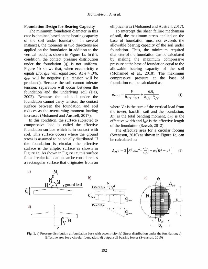
Foundation Design for Bearing Capacity
The minimum foundation diameter in this
case is obtained based on the bearing capacity
of the soil under foundation. In several
instances, the moments in two directions are
applied on the foundation in addition to the
vertical loads, as shown in Figure 1a. In this
condition, the contact pressure distribution
under the foundation (q) is not uniform.
Figure 1b shows that, when eccentricity e
equals B/6, qmin will equal zero. At e > B/6,
qmin will be negative (i.e. tension will be
produced). Because the soil cannot tolerate
tension, separation will occur between the
foundation and the underlying soil (Das,
2002). Because the sub-soil under the
foundation cannot carry tension, the contact
surface between the foundation and soil
reduces as the overturning moment loading
increases (Mohamed and Austrell, 2017).
In this condition, the surface subjected to
compressive load is called the effective
foundation surface which is in contact with
soil. This surface occurs where the ground
stress is assumed to be equally distributed. If
the foundation is circular, the effective
surface is the elliptic surface as shown in
Figure 1c. As shown in Figure 1c, this surface
for a circular foundation can be considered as
a rectangular surface that originates from an
elliptical area (Mohamed and Austrell, 2017).
To intercept the shear failure mechanism
of soil, the maximum stress applied on the
base of foundation must not exceeds the
allowable bearing capacity of the soil under
foundation. Thus, the minimum required
diameter of the foundation can be calculated
by making the maximum compressive
pressure at the base of foundation equal to the
allowable bearing capacity of the soil
(Mohamed et al., 2018). The maximum
compressive pressure at the base of
foundation can be calculated as:
𝑞𝑚𝑎𝑥 =𝑉
𝑏𝑒𝑓𝑓 𝑙𝑒𝑓𝑓+
6𝑀𝑡
𝑏𝑒𝑓𝑓 𝑙𝑒𝑓𝑓2 (1)
where V : is the sum of the vertical load from
the tower, backfill soil and the foundation,
Mt: is the total bending moment, beff: is the
effective width and leff: is the effective length
of the foundation (Szerző, 2012).
The effective area for a circular footing
(Svensson, 2010) as shown in Figure 1c, can
be calculated as:
𝐴𝑒𝑓𝑓 = 2 [𝑅2𝑐𝑜𝑠−1 (𝑒
𝑅) − 𝑒√𝑅2 − 𝑒2 ] (2)
Fig. 1. a) Pressure distribution at foundation base with eccentricity; b) Stress distribution under the foundation; c)
Effective area for a circular foundation; d) output soil bearing forces (Svensson, 2010)

Civil Engineering Infrastructures Journal, 53(1): 189 – 205, June2020
193
where e: is eccentricity (Figure 1d) and R: is
the raft radius (R = D/2). Eccentricity e can
be calculated as:
𝑒 =𝑀𝑡
𝑉 (3)
The equivalent rectangular footing of
dimensions (leff and beff) can be calculated
(Mohamed and Austrell, 2017) as:
𝑙𝑒𝑓𝑓 = √𝐴𝑒𝑓𝑓
𝑅√1−(1−(𝑅−𝑒)
𝑅)
2
(𝑅−𝑒) and
𝑏𝑒𝑓𝑓 =𝑙𝑒𝑓𝑓
𝑅√1−(1−(𝑅−𝑒)
𝑅)
2(𝑅 − 𝑒)
(4)
The sum of the vertical loads V and total
bending moment Mt can be calculated as:
𝑀𝑡 = 𝑀 + 𝐻 × 𝑑𝑓 (5)
𝑉 = 𝑁 + 𝑊𝑓 + 𝑊𝑠 − 𝐹 (6)
where H and N: are the horizontal and the
vertical loads respectively at the tower base,
M: is the bending moment at the tower base,
Wf : is the weight of the foundation, Ws: is the
weight of the backfill, df : is the foundation
buried depth as shown in Figure 1a, F: is the
uplift force from groundwater. In Figure 2,
these forces are calculated as:
𝑊𝑓 = 𝜋(𝑅22 × (𝐻2 + 𝐻1) + 𝑅2 × 𝐻3 +
1
2× (𝑅2 − 𝑅2
2) × 𝐻2)× 𝛾𝑐
(7)
𝑊𝑠 = 𝜋((𝑅2 − 𝑅22) × 𝐻1 +
1
2× (𝑅2 − 𝑅2
2) × 𝐻2) × 𝛾𝑠
(8)
𝐹 = 𝜋𝑅2𝛾𝑤(𝑑𝑓 − 𝑑𝑤) (9)
where dw: is the location of the groundwater
from the ground surface and R: is the footing
radius. Note that Eq. (7) is valid when the
groundwater table, dw, is less than the footing
base depth. This means that there is no uplift
force on the footing if dw > df.
As mentioned, the minimum diameter of
the foundation should be calculated by
making the maximum pressure stress under
the footing equal to allowable bearing
capacity qall (Mohamed and Austrell, 2017).
The qall value is obtained by separating the
theoretical maximum pressure which can be
supported without causing shear failure by a
safety factor (FS) that equals to 2 to 3
(Bowles, 1997; Terzaghi, 1943).
There are two ways of calculating qall that
depend on the ground conditions (Meyerhof,
1951; Schuppener, 2007; Skempton, 1984).
Under drained conditions, Meyerhof”s
equation can be used to calculate the
allowable bearing capacity as:
Fig. 2. Geometry of a spread foundation
𝑞𝑎𝑙𝑙 =𝑐𝑁𝑐𝑆𝑐𝑑𝑐𝑖𝑐𝑔𝑐𝑏𝑐 + 𝑞𝑁𝑞𝑆𝑞𝑑𝑞𝑖𝑞𝑔𝑞𝑏𝑞 + 0.5�́�𝑏𝑒𝑓𝑓𝑁𝛾𝑆𝛾𝑑𝛾𝑖𝛾𝑔𝛾𝑏𝛾
𝐹𝑆 (10)
where qall: is the allowable bearing capacity
of the foundation in kPa, which is calculated
by multiplying the effective soil density 𝛾́ by
the foundation base depth df. c: is cohesion
(kPa), q: is the stress at the foundation level
in kPa, �́�: is the effective soil density in
kN/m3, Nc, Nq, and Ny: are bearing capacity
factors which are a function of the internal
friction angle, Sc, Sq, and Sy: are shape factors,
dc, dq, and dy: are depth factors, ic, iq, and iy:

Motallebiyan, A. et al.
194
are load inclination factors, gc, gq, and gy: are
ground inclination factors and bc, bq, and by:
are base inclination factors. The value of qall
for undrained conditions is:
𝑞𝑎𝑙𝑙 =𝑐𝑢𝑁𝑐𝑆𝑐𝑑𝑐 + 𝑞
𝐹𝑆 (11)
where cu: is the undrained cohesion, Nc, Sc
and dc: are the bearing capacity factor, the
shape factor and the depth factor, respectively
(Skempton, 1984).
In the current study, Eq. (10) was used to
calculate the bearing capacity due to
groundwater level position which is located
in the depth of 27 m from the surface and the
soil behaves in a drained manner. The
minimum diameter can be calculated by
putting the maximum pressure from Eq. (1)
as equal to the allowable bearing capacity of
the soil from Eq. (10) or (11) as:
𝑞𝑎𝑙𝑙 − 𝑞𝑚𝑎𝑥 = 0 (12)
The minimum diameter of the foundation
is found from the equation in an iterative
manner, i.e., by assuming a diameter and
iterate until the residual of Eq. (12) becomes
small enough.
Foundation Design for Overturning
The resistance against overturning must be
considered because wind turbine foundations
have high overturning loads (Das, 2002). In
order to prevent overturning of a wind turbine
under wind loads, the wind load must be
balanced by reaction forces from the soil
layers under the foundation with eccentricity
e as shown in Figure 1. When e is equal to raft
radius R, the limiting case occurs
theoretically and stability moment Ms is
calculated as:
𝑀𝑠 = 𝑉 × 𝑅 (13)
Interception of overturning is a method of
defining the safety factor against overturning
as FS ≥ 1.5 with respect to Ms (Morgan and
Ntambakwa, 2008). In this case, FS is equal
to:
FS =𝑀𝑠
𝑀𝑡 (14)
Szerző (2012) suggested focusing on
eccentricity e, which should comply with:
𝑒 =𝑀𝑡
𝑉≤ 0.25𝑅 𝑓𝑜𝑟 𝑠𝑒𝑟𝑣𝑖𝑐𝑒 𝑙𝑜𝑎𝑑𝑠 𝑎𝑛𝑑≤ 0.58𝑅 𝑓𝑜𝑟 𝑢𝑙𝑡𝑖𝑚𝑎𝑡𝑒 𝑙𝑜𝑎𝑑𝑠
(15)
where R: is the raft radius (R = D/2), V: is the
sum of vertical loads and Mt: is the sum of the
total bending moment (Szerző, 2012).
According to the requirements of
overturning, the diameters of the footings are
calculated by Eqs. (14) and (15) with FS = 1.5
and e = 0.58 R. Total bending moment Mt can
be calculated using Eq. (5), the sum of the
vertical loads 𝑉 and stability moment 𝑀𝑠 can
be obtained by using Eqs. (6) and (13),
respectively.
By assuming a diameter and iterate for the
residuals of Eqs. (14) and (15), the diameter
of the foundation can be calculated using the
equation in an iterative manner. The required
diameters are the largest values obtained from
Eqs. (14) and (15) (Mohamed and Austrell,
2017).
Foundation Design for Settlement
The minimum foundation diameter in this
case is calculated by considering the
settlement of the foundation. In the current
study, the allowable differential settlement
and the maximum settlement of the
foundation are assumed 3 mm/m and 50 mm,
respectively. Because of groundwater level is
located in the depth of 27 m from the surface
we should use the theory of elasticity to
determine elastic settlement of shallow
foundations. The maximum settlement under
the foundation can be calculated as (Das,

Civil Engineering Infrastructures Journal, 53(1): 189 – 205, June2020
195
2007):
𝑆𝑒 = 𝑞(𝛼𝐵′)1 − 𝜗2
𝐸𝐼𝑠𝐼𝑓 (16)
where 𝑞: is net applied stress at the level of
the foundation, 𝛼: is a factor depending on the
location of the foundation where settlement is
being calculated, 𝐵′: is the width of
foundation, 𝐸: is the elastic modulus of soil,
𝜗: is Poisson’s ratio for the undrained
condition, 𝐼𝑠 and 𝐼𝑓: are shape and depth
factors respectively.
FINITE ELEMENT MODEL
In the current study, all numerical finite
element simulations were performed in
ABAQUS 6.12 and PLAXIS-3D Foundation
1.6. The details of the modeling approaches
are presented below.
Modeling in ABAQUS Software
In the current study, an elastic perfectly-
plastic constitutive model along with the
Mohr-Coulomb failure criterion were
selected to simulate the soil layers, similar
previous studies (Niels and Matti, 2005; Potts
and Zdravkovic, 1999). A fine-grid mesh
surrounded the foundation and a coarse-grid
mesh was used for the far field. As shown in
Figure 3a, to prevent the influence of
boundary conditions of the soil on the results,
the mesh boundaries extended 40 m from the
edge of the raft foundation. The depth of the
soil was determined by the bedrock depth in
the wind farms in Manjil which is 30 m below
the surface of the soil. To increase safety
factor and the possibility of flooding on the
site, foundation was simulated on the soil. An
8-node brick, reduced integration element
(C3D8R) was selected to model the
foundation, soil and steel ring. The parameter
values of the mesh are shown in Figure 3a for
29,568 elements and 34,386 nodes for the
soil.
Table 2 shows the values of applying the
loads include loads and moment to the turbine
foundation. Figure 3b shows the mesh and the
dimensions of the designed foundation,
which is circular with a diameter of 20 m and
height of 3 m.
The foundation was modeled as linearly
elastic 3D structures. Figure 3b also shows
the dimensions of the steel ring embedded in
the foundation. The properties of the soil,
steel ring and foundation concrete used in the
FE model are given in Table 3. To measure
the effect of foundation depth on the results,
the foundation was simulated in ABAQUS at
depths of 0, 3, 6 and 9 m.
As previously mentioned, when the
extremely high overturning moment is
applied on the wind turbine foundation results
in partial separation of the foundation from
the soil that has important effect on the
behavior of the foundation. Several types of
FE software, including PLAXIS-3D and 2D,
consider this interaction under static loading
and the nodes in the contact area between the
foundation and soil are common with no
possibility of separation between them.
Therefore, the soil is simulated with the
ability to carry tension stress which is
contrary to reality.
Table 3. Material properties
Description Unit weight γ
(kN/m3)
Young’s
modulus E (kPa)
Internal friction
angle φ (º)
Cohesion C'
(kPa)
Ψ
(º)
Poisson’s
ratio 𝝑
Soil properties 19 25000 34 10 4 0.35
Concrete
properties 25.5 20.59×10⁶ - - - 0.2
Steel properties 78.5 210×106 - - - 0.3

Motallebiyan, A. et al.
196
ABAQUS is able to model the partial
separation of the foundation from the soil
with normal behavior using the restriction
enforcement technique and pressure
overclosure as the hard contact, allowing
separation. The horizontal forces from the
wind-load can cause sliding; thus, a surface-
to-surface contact was created between soil
and foundation in ABAQUS, so that the
“tangential behavior” with a friction
coefficient of 0.3 has been defined as
properties of the contact. The interaction of
the embedded region was defined between
the steel ring and the concrete. The soil nodes
of the boundary surrounding the model were
fixed in the horizontal direction; however, the
nodes at the bottom boundary of the finite
element model were fixed.
Three steps were used in deformation
analysis. The first was the geostatic step to
ensure that equilibrium due to soil weight was
satisfied in the soil. The second was the static
general step to set the foundation on the soil.
The third was the static general step to apply
the tower loads as shown in Table 2.
Modeling in PLAXIS-3D Software
The Finite Element software PLAXIS-3D
Foundation 1.6 (Brinkgreve et al., 2012) was
used for simulation modeling. It is a Finite
Element software for analyzing soil and rock,
especially developed for analyzing stability
and deformation in geotechnical engineering.
Ten-node tetrahedral elements were utilized
to generate the finite element models of the
soil and foundation. Interface elements were
used between both the soil layer and the
foundation soil.
Figure 4a shows a PLAXIS-3D model
with its geometrical properties. To prevent
the influence of boundary conditions defined
for the soil on the results, mesh boundaries
extended out 40 m from the edge of the raft
foundation and the depth of the soil was
determined as the depth at bedrock as 30 m.
Displacement of the model boundaries
(bottom and all peripheries, plus normal
directions in symmetry) were fixed in all
directions. The soil characteristics are also
summarized in Table 3.
PLAXIS-3D is unable to simulate the
dimensions of the designed foundation with a
sloping surface as shown Figure 3c. In the
current study, the foundation was simulated
as stairway concrete foundation in PLAXIS-
3D (see Figure 4b). The foundation was
modeled as a linearly elastic 3D structure
with the concrete properties given in Table 3.
The numerical analyses were done in several
computational phases. The initial geometry
configuration and stress states have been
considered in the initial phase. The second
phase was for design of the foundation on the
soil and phase three was for the tower loads
(Table 2).
RESULTS AND DISCUSSION
In this section, the results of the software
analysis on the two examples defined in the
previous section will be displayed.
Maximum Settlement
It is not possible to consider the partial
separation of the foundation from the soil
when the SSI is not considered, which can
have an important effect on the maximum
settlement. If the SSI in ABAQUS is
considered, the maximum settlement under
the SLS loads for a foundation with a
diameter of 20 m on a siltstone layer is 3.13
cm. However, when this contact is not
considered in ABAQUS, the maximum
settlement is 3.06 cm. Also, the maximum
settlement under SLS loads in PLAXIS-3D
for a foundation with a diameter of 20 m on a
siltstone layer is 3.03 cm.

Civil Engineering Infrastructures Journal, 53(1): 189 – 205, June2020
197
Fig. 3. a) Three dimensional Finite Element model of the soil; b) Three dimensional Finite Element model of
foundation; c) Dimensions of the spread foundation; d) Finite Element model of soil foundation interaction
Fig. 4. a) Three dimensional finite element model of the soil and foundation in Plaxis-3D; b) Detailed Dimensions of
the spread foundation in Plaxis-3D

Motallebiyan, A. et al.
198
In addition, the maximum settlement
under UOM loads for the foundation is 3.81
cm with considering the SSI in ABAQUS. In
contrast, the maximum settlement is 3.62 cm
when the SSI is not considered. Also, the
maximum settlement due to UOM in
PLAXIS-3D for similar condition is 3.59 cm.
As can be seen, when there is no gap between
the foundation and soil in ABAQUS, the
maximum settlement obtained by ABAQUS
and PLAXIS-3D are mostly equal. The
difference in these results is a function of the
foundation diameter.
Figure 5a shows the effect of the
foundation diameter on the maximum
settlement. As shown in the figure, the
difference between the results of maximum
settlement increased with a decrease of the
diameter. The difference between the results
of the two methods versus e/D is shown in
Figure 5b. The results indicate that the
difference is not significant when e/D is less
than 1/6 and foundation does not separate
from the soil and so uplift does not occur.
However, for e/D greater than 1/6, the
difference between the results increases
significantly. Table 4 shows the results from
simplified calculation method by using Eqs.
(1-16) respectively to verify the accuracy of
the FE results. In order to use Eq. (16),
triangular load convert to equivalent uniform
rectangular load. As can be seen, the
maximum settlement obtained by ABAQUS
with considering the SSI are equal the
calculations.
The maximum settlements obtained from
ABAQUS and PLAXIS-3D by modeling a
foundation with a diameter of 20 m at
different depths on siltstone and mudstone
layers are shown in Figures 6a,b,
respectively. The results indicate that the
difference between the results is reduced due
to increasing of the embedded depth of the
foundations. The effects of cohesion and
internal friction angle of the soil on the
difference in the maximum settlement under
UOM loads in the two modes for a siltstone
layer as a function of depths are shown in
Figures 7 and 8, respectively.
As shown in Figure 7, the maximum
settlement is almost independent of soil
cohesion and the difference in the maximum
settlement in the two modes at a depth of 3 m
is more impressive than that in the other
depths (i.e. 0 and 9 m), while the results
presented in Figure 8 show that the angle
change of 20 to 30 has an important effect on
the maximum settlement at ground level.
Here, too, the greatest difference observed at
a depth of 3 m
3
4
5
6
7
8
9
10
15 16 17 18 19 20 21
Ma
xim
um
set
tlem
ent
S (
cm)
Diameter of the foundation (m)
Result of Abaqus with SSI
Result of Abaqus without SSI

Civil Engineering Infrastructures Journal, 53(1): 189 – 205, June2020
199
Fig. 5. a) Effect of the foundation diameter on the maximum settlement; b) The difference between the results of the
two methods (with or without considering the SSI) versus e/D
Table 4. Results of simplified calculation method
layer loads D 𝒅𝒇 𝑾𝒇
(𝒌𝑵)
𝑴𝒕 (𝒌𝑵)
𝑽 (𝒌𝑵)
𝒆 𝒃𝒆𝒇𝒇
(𝒎)
𝒒𝒎𝒂𝒙 (𝒌𝑷𝒂)
𝐅𝐒 ≥ 𝟏. 𝟓 𝑺𝒆
(𝒄𝒎)
Silt stone UOM
21 0 15907 60500 18617 3.2 12.4 188 3.23 3.6
20 0 14532 60500 17242 3.5 11.1 226 2.85 3.8
19 0 13224 60500 15934 3.8 9.7 283 2.5 4.2
18 0 11984 60500 14694 4.1 8.3 372 2.2 4.7
17 0 10810 60500 13520 4.5 6.8 528 1.9 5.5
16 0 9704 60500 12414 4.9 5.2 842 1.6 6.7
15 0 8664 60500 11374 5.3 3.6 1659 1.4 9.2
0
10
20
30
40
50
60
0.15 0.18 0.21 0.24 0.27 0.3 0.33 0.36
Ratio of 𝑒∕𝐷
0
1
2
3
4
5
6
7
8
9
10
2 2.2 2.4 2.6 2.8 3 3.2 3.4 3.6 3.8 4
Df
(m)
Max settlement (cm)
Result of Abaqus with SSI
Result of Plaxis-3D

Motallebiyan, A. et al.
200
Fig. 6. a) The maximum settlements obtained from ABAQUS and PLAXIS-3D by modeling a foundation on
siltstone layers; b) The maximum settlements obtained from ABAQUS and PLAXIS-3D by modeling a foundation
on mudstone layers.
0
1
2
3
4
5
6
7
8
9
10
0.7 0.8 0.9 1 1.1 1.2 1.3 1.4
Df
(m)
Max settlement (cm)
Usin Abaqus with considering interaction
Result of Plaxis-3D
1.5
2
2.5
3
3.5
4
0 10 20 30 40 50 60
Ma
xim
um
set
tlem
ent
(cm
)
C (KN/m²)
Result of Abaqus with SSI
Result of Abaqus without SSI

Civil Engineering Infrastructures Journal, 53(1): 189 – 205, June2020
201
Fig. 7. The effects of cohesion on the difference in the maximum settlement under UOM loads for a siltstone layer as
a function of depths at the depth of: a) 0 meter; b) 3 meter; c) 9 meter
1.5
2
2.5
3
3.5
4
0 10 20 30 40 50 60
Ma
xim
um
set
tlem
ent
(cm
)
C (KN/m²)
Result of Abaqus with SSI
Result of Abaqus without SSI
1.5
2
2.5
3
3.5
4
0 10 20 30 40 50 60
Ma
xim
um
set
tlem
ent
(cm
)
C (KN/m²)
Result of Abaqus with SSI
Result of Abaqus without SSI

Motallebiyan, A. et al.
202
1.5
2
2.5
3
3.5
4
4.5
5
10 20 30 40 50 60
Ma
xim
um
set
tlem
ent
(cm
)
Internal friction angle φ'(º)
Result of Abaqus with SSI
Result of Abaqus without SSI
1.5
2
2.5
3
3.5
4
4.5
5
10 15 20 25 30 35 40 45 50 55
Ma
xim
um
set
tlem
ent
(cm
)
Internal friction angle φ'(º)
Result of Abaqus with SSI
Result of Abaqus without SSI

Civil Engineering Infrastructures Journal, 53(1): 189 – 205, June2020
203
Fig. 8. The effects of internal friction angle on the difference in the maximum settlement under UOM loads for a
siltstone layer as a function of depths at the depth of: a) 0 meter; b) 3 meter; c) 9 meter
Stress under the Foundation
Generally, it is accepted that soil layers are
not capable of resisting significant tensile
forces. For this reason, when the ultimate
overturning loads applied the foundation and
e/D exceeds 1/6, these loads will cause a gap
between the foundation and the supporting
soil. Under these conditions, the vertical
stress in the gap becomes zero. Figure 9
shows the amount of vertical stress under a
foundation with a diameter of 20m along a
line between the maximum and the minimum
settlement. As shown in the results, the value
of vertical stress along the edge of the
foundation (point A) to an approximate
distance of 3.5 m was zero, when the SSI was
defined. This indicates that the foundation
has been separated from the supporting soil.
Fig. 9. The amount of vertical stress under the foundation with a diameter of 20 m using line AB between the
maximum and the minimum settlement
1.5
2
2.5
3
3.5
4
4.5
5
10 20 30 40 50 60
Ma
xim
um
set
tlem
ent
(cm
)
Internal friction angle φ'(º)
Result of Abaqus with SSI
Result of Abaqus without SSI
-0.35
-0.3
-0.25
-0.2
-0.15
-0.1
-0.05
0
0.05
0 5 10 15 20
Str
ess
(M
N/m
2)
Distance from point A (m)
Result of Abaquse with SSI
Result of Abaqus without SSI

Motallebiyan, A. et al.
204
The results obtained from modeling the
same foundation without defining the SSI is
shown also in Figure 9. The tensile stress can
be observed even at point A. In this condition,
the foundation has not been separated from
the supporting soil, because the SSI has not
been defined. When e/D exceeds 1/6, the
UOM loads lead to upward movement of the
foundation that result in tensile stress on the
part of the supporting soil area.
CONCLUSIONS
The current study examined the effect of SSI
on the static response of onshore wind turbine
foundations and compared the maximum
settlement obtained by ABAQUS and
PLAXIS-3D. The results of FE analysis
indicate that SSI has important effect on the
maximum settlement and stress distribution
under the foundation. The results show that
when in FE software, a spread turbine
foundation is applied eccentricity forces, if
e/D is less than 1/6, the SSI has not effect on
the difference of maximum settlement;
however, when e/D exceeds 1/6 (with
decreasing the diameter of foundation), a part
of the foundation base area will be subjected
to tension stresses; thus, the difference in
maximum settlement increases.
Under these conditions, the vertical stress
in the gap becomes zero when the SSI was
defined but the results obtained from
modeling the same foundation without
defining the SSI indicated that tensile stress
on the part of the supporting soil area can be
observed and the existence of tensile stress
under the foundation was the cause of the
error in the results. The results also showed
that, when the depth of the foundation
increased in response to the growing
overhead force, the difference in maximum
settlement decreased; however, the cohesion
and friction angle of the soil had no effect on
the difference in the results of maximum
settlement.
According to the results when there is no
gap between the foundation and soil in
ABAQUS, the maximum settlement obtained
by ABAQUS and PLAXIS-3D are mostly
equal. Because FE software such as PLAXIS-
3D and 2D are unable to define the SSI and
cannot simulate the behavior of the
foundation and soil when e/D exceeds 1/6 as
well as is possible in ABAQUS.
REFERENCES
Austin, S. and Jerath, S. (2017). "Effect of soil-
foundation-structure interaction on the seismic
response of wind turbines", Ain Shams Engineering
Journal, 8(3), 323–331.
Bhattacharya, S., Nikitas, G., Arany, L. and Nikitas, N.
(2017). "Soil-Structure Interactions (SSI) for
offshore wind turbines", The Institution of
Engineering and Technology, 24(16), 1-23.
Bowles, L. (1997). Foundation analysis and design,
McGraw-hill.
Brinkgreve, R.B.J., Engin, E. and Swolfs, W.M.
(2012). "Plaxis 3D 2012", Plaxis bv, the
Netherlands.
Cabalar, A.F., Uyan, R.S. and Akbulut,N. (2016). "A
Study of Foundation Design for Wind Turbines in
Hasanbeyli, Turkey", Soil Mechanics and
Foundation Engineering, 53(5), 298-303.
Das, B.M. (2002). Principles of Foundation
Engineering, McGraw-Hill handbooks.
Ishihara, T., Ishii, H. and Nishio, M. (2011). Maximum
wind loads on a wind turbine under operating
conditions, European Wind Energy Association:
Europe's Premier Wind Energy Event.
Ishii, H. and Ishihara, T. (2010). "Numerical study of
maximum wind load on wind turbine towers under
operating conditions", The Fifth International
Symposium on Computational Wind Engineering
(CWE2010), Chapel Hill, North Carolina, USA,
May 23-27, pp. 1-8
Jamshidi Chenari, R., Ghorbani, A., Eslami, A. and
Mirabbasi, F. (2018). "Behavior of piled raft
foundation on heterogeneous clay deposits using
random field theory", Civil Engineering
Infrastructures Journal, 51(1), 35-54.
Kawai, H., Michishita, K. and Deguchi, A. (2008).
"Design wind loads on a wind turbine for strong
wind", Proceedings of the BBAA VI International
Colloquium on: Bluff Bodies Aerodynamics and
Applications, Milano, Italy, Vol. 2024.
Lantz, E., Leventhal, M. and Baring-Gould, I. (2013).
Wind power project repowering: Financial

Civil Engineering Infrastructures Journal, 53(1): 189 – 205, June2020
205
feasibility, decision drivers, and supply chain
effects, National Renewable Energy Laboratory
(NREL).
Meyerhof, G.G. (1951). "The ultimate bearing
capacity of foundations", Géotechnique, 2(4), 301-
332.
Mohamed, W. and Austrell, P.E. (2017). "A
comparative study of three onshore wind turbine
foundation solutions", Computers and
Geotechnics, 94, 46-57.
Mohamed, W., Austrell, P.E. and Dahlblom, O.
(2018). "A new and reusable foundation solution
for onshore windmills", Computers and
Geotechnics, 99(February), 14-30.
Morgan, K. and Ntambakwa, E. (2008). "Wind turbine
foundation behavior and design considerations",
Proceedings of the American Wind Energy
Association Windpower Conference, Houston,
Texas.
Morshedifard, A. and Eskandari-Ghadi, M. (2017).
"Coupled BE-FE scheme for three-dimensional
dynamic interaction of a transversely isotropic
half-space with a flexible structure", Civil
Engineering Infrastructures Journal, 50(1), 95-
118.
Mortezaie, H. and Rezaie, F. (2018). "Seismic
behavior and dissipated plastic energy of
performance-based-designed high-rise concrete
structures with considering soil–structure
interaction effect", Civil Engineering
Infrastructures Journal, 51(1), 199-215.
Mostafaeipour, A. and Abarghooei, H. (2008).
"Harnessing wind energy at Manjil area located in
north of Iran", Renewable and Sustainable Energy
Reviews, 12(6), 1758-1766.
Niels, S.O. and Matti, R. (2005). The mechanics of
constitutive modeling, Elsevier.
Potts, D. and Zdravkovic, L. (1999). Finite Element
analysis in geotechnical engineering: Application,
Vol. 1, Thomas Telford.
Ripa Alonso, T. and González Dueñas, E. (2014).
"Cracks analysis in onshore wind turbine
foundations", IABSE Symposium Report, 102(23),
1086-1092.
Salmasi, F., Mansuri, B. and Raufi, A. (2015). "Use of
numerical simulation to measure the effect of relief
wells for decreasing uplift in a homogeneous earth
dam", Civil Engineering Infrastructures Journal,
48(1), 35‑45.
Schuppener, B. (2007). "Eurocode 7: Geotechnical
design, Part 1: General rules-its implementation in
the European member states", Proceedings of the
14th European Conference on Soil Mechanics and
Geotechnical Engineering, Madrid, Spain, 24-27
September, 2, 279-289.
Svensson, H. (2010). "Design of foundations for wind
turbines", M.Sc. Dissertation, Lund University.
Szerző, Á. (2012). "Optimization of foundation
solutions for wind turbines", Mathematical
Modeling in Civil Engineering, 4, 215-225.
Terzaghi, K. (1951). Theoretical soil mechanics,
JohnWiley & Sons, New York, 11-15.