analytical solutions for lag/lead and general second order compensator design problems · ·...
TRANSCRIPT
Analytical Solutions for Lag/Lead and General Second Order Compensator Design Problems
Fei-Yue Wang, Fellow, IEEE
Abstract- This paper presents a simple method for determining
analytical solutions to lag/lead cascade and general second order compensator design problems in the frequency domain. Only linear and quadratic equations are used in the proposed approach. Results obtained here can be used to eliminate conventional graphic-based trial-and-error method used in past and contemporary control textbooks, which are tedious and time-consuming, and rewrite them into simple and analytical non-trial-and-error steps.
Index Terms—Lag/lead compensators, cascade compensation,
trial-and-error, analytic solution.
1. INTRODUCTION Although control system design has made tremendous
progress over the last three decades, and advanced mathematic concepts, methods, and tools are used extensively in modern control theory, many industrial control systems are still designed by simple procedures in the frequency domain, especially the PID and lag/lead cascade compensation. Those classical approaches are very valuable due to their simplicity, particularly when no analytical plant models are unknown and only experimental data in frequency domain are available. Since the cascade compensation was first introduced, the determination of compensators has always been carried out by the conventional graphic-based trial-and-error design method, as one can see from all available past and contemporary textbooks in control [11-20]. Usually, an appropriate compensator can be obtained only after many trials and errors, usually a tedious and time-consuming process.
From the control educational point of view, many consider the frequency domain design as “physics” of communication, control, and signal processing systems, especially when mathematics plays a more and more important role in teaching, research, and application of those fields in the modern age. This is quite natural and justified since frequency domain design methods expose students and engineers to variables and concepts that can be directly related to phenomena and quantities in the physical world, not just some heavy doses of matrices, equations, and their manipulations in mathematics. This is part of the reason why frequency domain design is still play a fundamental role in both engineering education and industrial applications.
However, due to the nature of conventional trial-and-error graphical techniques currently used by almost all available textbooks [11-20], learning and use of cascade compensation are still a time consuming process, and become more serious a problem in teaching and applications now since computers are used for everything and students are pressed for time in learning new and old
subjects. Starting from Wakeland and Mitchell in 1970s [1-4], Yeung, et al and Wang in 1990s [5-10], various efforts have been made to develop analytical or computer-aided design procedures for lag and lead compensation with limited and partial success.
In this paper, we present a simple method for finding analytical solutions to lag/lead cascade and general second order compensation design problems. In this approach, using Euler formula for complex numbers, only linear equations are involved for solving unknown design parameters, no nonlinear or transcendental equations as in previous works. The proposed analytical solutions can be used as the basis to eliminate and rewrite traditional trial-and-error procedures in control textbooks into analytical non-trial-and-error steps for determining cascade compensators in frequency domain.
2. DESIGN SPECIFICATION FOR
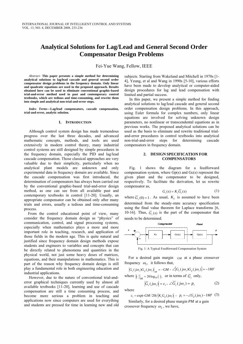
COMPENSATORS Fig. 1 shows the diagram for a feedforward
compensation system, where Gp(s) and Gc(s) represent the given plant and the compensator to be designed, respectively. To facilitate the derivation, let us rewrite compensator as,
)()( sGKsG ccc = (1) where 1)0( =cG . As usual, cK is assumed to have been determined from the steady-state accuracy specification using the final value theorem for Laplace transforms [6, 10-16]. Thus, )(sGc
is the part of the compensator that needs to be determined.
Fig. 1: A Typical Feedforward Compensation System
For a desired gain margin GM at a phase crossover frequency 1,ω it follows that,
GMjGjGdBpc −=)()( 11 ωω , { } o
11 180)()( −=∠ ωω jGjG pc
where ( ) ( )1020log ,dB
⋅ = ⋅ or in terms of cG only,
11 )( cjGc =ω , 11 )( pjGc =∠ ω (2)
where )(/)20/exp( 11 ωjGKGMc pc−= , o
11 180)( −−∠= ωjGp p (3)
Similarly, for a desired phase margin PM at a gain crossover frequency 2ω , we have,
INTERNATIONAL JOURNAL OF INTELLIGENT CONTROL AND SYSTEMSVOL. 13, NO. 4, DECEMBER 2008, 233-236

0)()( 22 =dBpc jGjG ωω , { } o
22 180)()( −=∠ PMjGjG pc ωω
or in terms of cG only,
22 )( cjGc =ω , 22 )( pjGc =∠ ω (4)
where )(/1 22 ωjGKc pc= , o
22 180)( −∠−= ωjGPMp p
Using Euler’s Formula, we can rewrite Eqs. (2) and (4) into the following form,
)sin(cos)( iiijp
iic pjpcecjG i +==ω , 2,1=i (5) Eq. (5) serves as the step stone to our analytical solution for designing lag/lead or general second order compensators.
Note that in most of control textbooks [10-16], among margins GM, PM and crossover frequencies 1,ω 2ω , only two or three of them are specified in compensator design. This is mainly due to two considerations. First, some of those parameters are not provided in actual design; second, and most importantly, the conventional trial-and-error graphical method does not allow all four parameters to be specified. In this paper, however, we assume all four are given and other cases can be considered easily based on our analytical solution, as indicated for a special class of three-parameter compensators in our previous work [8, 9].
3. SINGLE LAG OR LEAD COMPENSATORS A single phase lag or lead compensator is expressed as,
ssGc τ
ατ++
=1
1 (6)
where α < 1 or α > 1 indicates a lag or lead compensator, respectively. Based on specification (2) or (4), we have,
cjGc =)( ω , pjGc =∠ )( ω (7)
where (c, p, cω ) is either (c1, p1, 1ω ) or (c2, p2, 2ω ). As indicated by Eq. (5), comparing the real and
imaginary parts of Eq. (7), we can find easily that,
1cos)cos(
−−
=pc
pccα , pc
pcsin
1cosω
τ −= (8)
Since 2/2/ ππ <<− p , we have 0cos >p , thus, 21/1cos δ+=p
where ( )tan .pδ = Therefore, in terms of δ ,
2
2
1)11(
δ
δα+−
−+=
ccc ,
δωδτ
cc 21+−
= (9)
which are identical with the result given in [8], however, the derivation process in [8] is much more complicated and involves nonlinear and transcendental equations.
From [8], the lead/lag compensation theorem for single phase lead or lag compensators can be stated as,
a) A single phase lead compensator exists if and only if, c<+ 21 δ , 0>δ ,
b) A single phase lag compensator exists if and only if, c/11 2 <+δ , 0<δ .
4. THREE-PARAMETER LAG-LEAD
COMPENSATORS A special class of three-parameter lag-lead compensators
has been proposed and studied in [6, 9], they can be expressed as,
ss
sssGc σ
βστατ
++
⋅++
=1
11
1)( (10)
where 0, 0, 0, 0.τ σ α β> > > > Parameters α and β are related by 1.αβ =
Substitute s with jω in Eq. (10), we have,
( ) ( )( )
11c
jG j
jω
ωω
+ Δ Γ=
+ Δ
where,
( ) ( )2,
1
τ σ ωατ βσ ωτ σ τσω
++Γ = Δ =
+ −
Based on Eq. (5), we find that,
1cos)cos(),(
−−
=Γpc
pccc δ , pc
pccsin
1cos),(ω
δ −=Δ (11)
or in terms of δ ,
( )( )
( )2
2
2
1 1 1, , ,1
c c cc ccc
δ δδ δδδ
+ − − +Γ = Δ =
− +
which are identical with the result given in [9], again, the derivation process is much simpler here.
From Γ and Δ , we can find ( ), , ,τ σ α β easily, as one can see in [9] or from the next section.
5. GENERAL LAG/LEAD COMPENSATORS In general, for a lag-lag, lag-lead, or lead-lead serial
combination, we have,
2
2
)(1)(1
11
11)(
ssss
ss
sssG c
τσστατβσβσατσβσ
τατ
++++++
=
++
⋅++
= (12)
where 0, 0, 0, 0.τ σ α β> > > > Substitute s with jω in Eq. (12), we have,
43
21
)()()(
Λ+ΩΛ+Ω
=jjjGc ω
ωω
where, ατβσ=Λ1 , βσατ +=Λ 2 , τσ=Λ3
, στ +=Λ 4 ,
ωωω
21
11)( Λ−
=Ω , ωωω
23
31)( Λ−
=Ω (13)
Define, iii pcA cos= , iii pcB sin= , 2,1=i
then, Eq. (5) leads to the following linear equations,
),,,,,(),,,,,(
221121
221121
BABANBABAM
ωωωω
=Λ (14)
where
234 INTERNATIONAL JOURNAL OF INTELLIGENT CONTROL AND SYSTEMS, VOL. 13, NO. 4, DECEMBER 2008

⎥⎥⎥⎥
⎦
⎤
⎢⎢⎢⎢
⎣
⎡
ΛΛΛΛ
=Λ
4
3
2
1
,
⎥⎥⎥⎥
⎦
⎤
⎢⎢⎢⎢
⎣
⎡
−−−−−−
=
222
2222
111
1111
100100
ABBAABBA
M
ωωωωωω
,
⎥⎥⎥⎥
⎦
⎤
⎢⎢⎢⎢
⎣
⎡
−
−
=
22
22
11
11
//)1(
//)1(
ωω
ωω
BA
BA
N
Once Λ is found from Eq. (14), ( ), , ,τ σ α β can calculated by solving two quadratic equations as,
2/)4(),( 3244 Λ−Λ±Λ=στ ; (15)
2/)4(),( 1222 Λ−Λ±Λ=βσατ (16)
where plus ‘+’ is for τ and α and minus ‘-’ is for σ and β. Note that actually this process will lead to four solutions, corresponding to
( ), , ,τ σ α β ,
( ), , , ,σ τ β α
( ), , / , /τ σ βσ τ ατ σ , and
( ), , / , /σ τ ατ σ βσ τ respectively. Clearly, all four lead to the same final combination for lag/lead compensation.
6. GENERAL SECOND-ORDER COMPENSATORS
Consider a general second compensator in the form of,
11)(
12
2
12
2
++++
=sbsbsasasGc
, (17)
where 0>iiba , 2,1=i . Substitute s with jω in Eq. (17), from Eq. (5), we have,
),,,,,(
),,,,,(
221121
221121
BABANBABAM
ωωχωω
= (18)
where M and N is same as in the previous section, and [ ]Tbbaa 2121=χ .
Solving linear equations (18), we find the compensator immediately. Generally, compensator in (17) can not be factorized into a series of two lead or lag compensators.
To consider the case that the original point is a pole for compensation, such as the case of PID compensation, we can assume a new form for )(sGc
,
)1(1)(
12
2
12
2
++++
=sbsbssasasGc
.
In this case, the compensator can be determined from Eq. (18) by replacing Ai and Bi according to the following rule,
iii BA ω−→ , iii AB ω→ .
7. CONCLUSIONS
In this paper, we present a set of analytic solutions to various compensator design problems in the classical control analysis and design in frequency domain. Based those analytic solutions, we can eliminate completely the need for the conventional graphic-based trial-and-error
method used for such problems and practiced by students in classrooms and engineers in industry since the very begin of control as an independent disciplinary, as one can see from all the contemporary textbooks in control. Related textbook and educational issues will be addressed elsewhere.
ACKNOWLEDGEMENT
This work was supported in part several research funds from the US National Science Foundation, and the National Natural Science Foundation, and the 973 Key Project from the Ministry of Science and Technology, China.
REFERENCES [1] W. R. Wakeland, “Bode compensator design,” IEEE Transactions
on Automatic Control, Vol. 21, 1976, 771-773. [2] J. Mitchell and W. Jr. McDaniel, “A computerized compensator
design algorithm with launch vehicle applications”, IEEE Transactions on Automatic Control, Vol.21, (3), 1976, 366 -371.
[3] J. R. Mitchell, “Comments on Bode compensator design,” IEEE Transactions on Automatic Control, Vol. 21, 1976, 771-773.
[4] K. S. Yeung and K. Q. Chaid, “Bode design for discrete compensators,” Electronics Letters, Vol. 22, No. 2, 1989, 22-24.
[5] K. S. Yeung, K. Q. Chaid and T. X. Dinh, “Bode design charts for continuous-time and discrete-time compensators,” IEEE Transactions on Education, Vol. 38, 1995, 252-257.
[6] K. S. Yeung, K. W. Wong and K.-L. Chen, “A non-trial-and-error method for lag-lead compensator design,” IEEE Transactions on Education, Vol. 41, 1998, 76-80.
[7] K. S. Yeung and K. H. Lee, “A Universal Design Chart for Linear Time-Invariant Continuous-Time and Discrete-Time Compensators,” IEEE Transactions on Education, Vol. 43, No.3, 2000, 309-315.
[8] Hugo Calleja, “An approach to amplifier frequency compensation,” IEEE Transactions on Education, Vol. 46, No. 1, 2003, pp.43-49.
[9] Fei-Yue Wang, “The exact and unique solution for phase-lead and phase-lag compensation,” IEEE Transactions on Education, Vol. 46, No. 2, May 2003, pp.258-262.
[10] Fei-Yue Wang, “A new non-trial-and-error method for lag-lead compensator design, part I: a special case,” The International Journal of Intelligent Control and Systems, pp.68-78, Vol. 11, No. 1, 2006.
[11] R. C. Dorf and R. H.Bishop, Modern Control Systems, 8th Ed. Menlo Park, CA: Addison-Wesley, 1998.
[12] B. C. Kuo and F. Golnaraghi, Automatic Control Systems, 8th Ed. Englewood Cliffs, NJ: Prentice-Hall, 2003.
[13] J. L. Melsa and D. G. Shultz, Linear Control Systems, New York: McGraw-Hill, 1969.
[14] N. S. Nise, Control Systems Engineering, New York: Wiley, 2000. [15] W. J. Palm III, Modeling, Analysis and Control of Dynamic
Systems, New York: Wiley, 1983. [16] N. K. Sinha, Control Systems, New York: Holt, Rinehart and
Winston, 1984 [17] R. T. Stefani, C. J. Savant Jr, B. Shahian, and G. H. Hostetter,
Design of Feedback Control Systems, New York: Oxford University Press, 1993.
[18] J. G. Truxal, Automatic Feedback Control System Synthesis, New York, McGraw-Hill, 1955.
[19] J. G. Truxal, Control Engineer's Handbook; Servomechanisms, Regulators, and Automatic Feedback Control Systems, New York, McGraw-Hill, 1955.
[20] W. A. Wolovich, Automatic Control Systems: Basic Analysis and Design, New York: Oxford University Press, 1993.
Wang: Analytical Solutions for Lag/Lead and General Second Order Compensator Design Problems 235
Fei-Yue Wang received Ph.D. in Electrical, Computer and Systems Engineering from the Rensselaer Polytechnic Institute, Troy, New York in 1990. He jointed the University of Arizona in 1990 and currently is a Professor and the Director of the Program for Advanced Research in Complex Systems. In 1999, he found the Intelligent Control and Systems Engineering Center at the Institute of Automation,
Chinese Academy of Sciences, Beijing, China, under the support of the Outstanding Oversea Chinese Talents Program. Since 2002, he is the Director of the Key Laboratory of Complex Systems and Intelligence Science at the Chinese Academy of Sciences. His current research interests include modeling, analysis, and control mechanism of complex systems; agent-based control systems; intelligent control systems; real-time embedded systems, application specific operating systems (ASOS); applications in intelligent transportation systems, intelligent vehicles and telematics, web caching and service caching, smart appliances and home systems, and network-based automation systems. He has published more than 200 book, book chapters, and papers in those areas since 1984 and received more than $20M USD and over ¥50M RMB from NSF, DOE, DOT, NNSF, CAS, MOST, Caterpillar, IBM, HP, AT&T, GM, BHP, RVSI, ABB, and Kelon. He received Caterpillar Research Invention Award with Dr. P.J.A. Lever in 1994 for his work in robotic excavation and the National Outstanding Young Scientist Research Award from the National Natural Science Foundation of China in 2001, as well as various industrial awards for his applied research from major corporations.received B.S. degree in computer engineering in 1983 from Institute of Engineering and Technology, China, and M.S. and Ph.D. degrees in computer science in 1988 and 1997 from the National University of Defense Technology (NUDT), China.
He was the Editor-in-Chief of the International Journal of Intelligent Control and Systems from 1995 to 2000, Editor-in-Charge of Series in Intelligent Control and Intelligent Automation from 1994 to 2004, and currently is the Editor-in-Charge of Series in Complex Systems and Intelligence Science, ITS Department Editor and Associate Editor of the IEEE Intelligent Systems, and Associate Editor of the IEEE Transactions on Systems, Man, and Cybernetics, IEEE Transactions on Robotics and Automation, IEEE Transactions on Intelligent Transportation Systems, and several other international journals. He is an elected member of IEEE SMC Board of Governors, ITSC AdCom, Nano Tech Council, the Secretary and VP for Administrative Affairs of IEEE Intelligent Transportation Systems Council, and the President-Elect of IEEE ITS Society, He was the Program Chair of the 1998 IEEE Int’l Symposium on Intelligent Control, the 2001 IEEE Int’l Conference on Systems, Man, and Cybernetics, Chair for Workshops and Tutorials for 2002 IEEE Int’l Conf. on Decision and Control (CDC), the General Chair of the 2003 IEEE Int’l Conference on Intelligent Transportation Systems, and will be Co-Program Chair of the 2004 IEEE Int’l Symposium on Intelligent Vehicles and the General Chair for the same conference in 2005. He was the Vice President and one of the major contributors of the American Zhu Kezhen Education Foundation, and a member of the Boards of Directors of five companies in information technology and automation. Dr. Wang
is also a member of Sigma Xi, ACM, AMSE, ASEE, and International Council of Systems Engineering (INCOSE).
236 INTERNATIONAL JOURNAL OF INTELLIGENT CONTROL AND SYSTEMS, VOL. 13, NO. 4, DECEMBER 2008