analytical fuselage and wing weight estimation of ...jps7/aircraft design resources... · t(y)...
TRANSCRIPT

National Aeronautics and Space Administration Ames Research Center Moffett Field, California 94035-1000
Mark D. Ardema, Mark C. Chambers,Anthony P. Patron, Andrew S. Hahn,Hirokazu Miura, and Mark D. Moore
NASA Technical Memorandum 110392
Analytical Fuselage and WingWeight Estimation of TransportAircraft
May 1996

National Aeronautics and Space Administration Ames Research Center Moffett Field, California 94035-1000
NASA Technical Memorandum 110392
May 1996
Analytical Fuselage and WingWeight Estimation of TransportAircraftMark D. Ardema, Mark C. Chambers, and Anthony P. Patron, Santa Clara University,Santa Clara, CaliforniaAndrew S. Hahn, Hirokazu Miura, and Mark D. Moore, Ames Research Center,Moffett Field, California

iii
Nomenclature
A fuselage cross-sectional area
AB fuselage surface area
AF frame cross-sectional area
(AR) aspect ratio of wing
b wingspan; intercept of regression line
bs stiffener spacing
bS wing structural semispan, measured alongquarter chord from fuselage
bw stiffener depth
CF Shanley’s constant
CP center of pressure
CR root chord of wing at fuselage intersection
′CR theoretical root chord of wing
Cs1 portion of wing leading edge not used forstructural box
Cs2 portion of wing trailing edge not used forstructural box
CSR structural root chord of wing
CST structural tip chord of wing
CT tip chord of wing
d frame spacing
dW optimum web spacing of wing
D maximum diameter of fuselage
e wing buckling exponent
eC wing cover material factor
E Young’s modulus of shell material
EF Young’s modulus of frame material
Fcy compressive yield strength
FS shear strength
Ftu ultimate tensile strength
h thickness of sandwich shell
hei step function for ith engine on wing
hlgi step function for ith landing gear on wing
IF frame cross-sectional area moment of inertia
Iy area moment of inertia about the y-axis
′Iy I ty s/
KF1 frame stiffness coefficient, I AF F/ 2
Kmg shell minimum gage factor
KP shell geometry factor for hoop stress
KS constant for shear stress in wing
Kth sandwich thickness parameter
lB fuselage length
lLE length from leading edge to structural box attheoretical root chord
lMG length from nose to fuselage mounted maingear
lNG length from nose to nose gear
lTE length from trailing edge to structural box attheoretical root chord
l1 length of nose portion of fuselage
l2 length of tail portion of fuselage
lπ length from nose to breakpoint of fuselage
L lift
LT maximum vertical tail lift
m buckling equation exponent; slope ofregression line
M longitudinal bending moment
n normal load factor
nx longitudinal acceleration
NxA axial stress resultant
NxB bending stress resultant
NxP pressure stress resultant
Nx+ tensile axial stress resultant
Nx− compressive axial stress resultant
Ny hoop direction stress resultant
P perimeter
Pg internal gage pressure
Ps perimeter of shell
Pw perimeter of walls
P1 exponent of power law of nose section offuselage
P2 exponent of power law of tail section offuselage
r radius of fuselage

iv
r(y) total wing chord as a function of positionalong quarter chord
rs(y) structural wing chord as a function of positionalong quarter chord
R correlation coefficient used for regression
Rfin fineness ratio
RHT ratio of horizontal tail station to fuselagelength
RLE ratio of wing leading edge station attheoretical root chord to fuselage length
RMG ratio of length to main gear to fuselage length
RNG ratio of length to nose gear to fuselage length
RP1 ratio of length to leading edge of fuselagemounted propulsion to fuselage length
RP2 ratio of length to trailing edge of fuselagemounted propulsion to fuselage length
Rt(y) thickness ratio of wing as a function ofposition along quarter chord
RTAP taper ratio of wing
SB plan area of the fuselage
SLG stroke of landing gear
SP plan area of wing
t(y) thickness of wing box as a function of positionalong quarter chord
tc core thickness
tf face sheet thickness
tg material gage thickness, t Ks mg/
tmg material minimum gage thickness
ts skin thickness
tw stiffener thickness
t total equivalent isotropic thickness of shell andframes
tB total equivalent isotropic thickness of fuselagestructure
tF smeared equivalent isotropic thickness offrames
tS equivalent isotropic thickness of shell
tSB shell thickness required to preclude bucklingfailure
tSC shell thickness required to precludecompressive failure
tSG shell thickness required to meet minimumgage constraint
tST shell thickness required to preclude tensilefailure
tT smeared tension tie thickness
tw smeared wall thickness
twG thickness of wall to meet minimum gageconstraint
twT thickness of wall required to prevent tensilefailure
T torque on wing carrythrough structure
VB fuselage volume
VW volume of wing structural box, includingstructural components
V1 volume of nose section of fuselage
V2 volume of tail section of fuselage
wC width of carrythrough structure of wing
W weight of aircraft structure
′W weight of wing per unit span
WB weight of fuselage structure and attachedcomponents
WFT weight of fuel
WI ideal fuselage structural weight
WNO weight of nonoptimum material
WS vehicle longitudinal weight distribution
WTO gross takeoff weight of aircraft
W/S shell structural weight per unit surface area
x longitudinal fuselage coordinate
xcalc weight calculated by PDCYL
xHT distance from nose to theoretical quarter chordof horizontal tail
xLE distance from nose to leading edge of wing attheoretical root chord
xP1 distance from nose to leading edge of fuselagemounted propulsion
xP2 distance from nose to trailing edge of fuselagemounted propulsion

v
y transverse fuselage coordinate; wingcoordinate measured along quarter chord
yact actual weight
yest estimated weight after regression
z vertical fuselage coordinate
Z(y) total width of wing box as a function ofposition along quarter chord
ZS(y) width of wing box structure as a function ofposition along quarter chord
δ frame deflection
ε shell buckling efficiency
εC wing cover structural efficiency
εW wing web structural efficiency
Λ wing sweep
µ wing loading
ρ structural material density
ρB gross fuselage density
ρF frame structural material density
σS allowable shear stress for wing
Σ sum over fuselage or wing length; solidity ofwing
ψ truss core angle

Analytical Fuselage and Wing Weight Estimation of Transport Aircraft
MARK D. ARDEMA,* MARK C. CHAMBERS,* ANTHONY P. PATRON,* ANDREW S. HAHN,HIROKAZU MIURA, AND MARK D. MOORE
Ames Research Center
Summary
A method of estimating the load-bearing fuselage weightand wing weight of transport aircraft based on funda-mental structural principles has been developed. Thismethod of weight estimation represents a compromisebetween the rapid assessment of component weight usingempirical methods based on actual weights of existingaircraft, and detailed, but time-consuming, analysis usingthe finite element method. The method was applied toeight existing subsonic transports for validation and corre-lation. Integration of the resulting computer program,PDCYL, has been made into the weights-calculatingmodule of the AirCraft SYNThesis (ACSYNT) computerprogram. ACSYNT has traditionally used only empiricalweight estimation methods; PDCYL adds to ACSYNT arapid, accurate means of assessing the fuselage and wingweights of unconventional aircraft. PDCYL also allowsflexibility in the choice of structural concept, as well as adirect means of determining the impact of advancedmaterials on structural weight.
Using statistical analysis techniques, relations betweenthe load-bearing fuselage and wing weights calculated byPDCYL and corresponding actual weights were deter-mined. A User’s Manual and two sample outputs, one fora typical transport and another for an advanced conceptvehicle, are given in the appendices.
Introduction
A methodology based on fundamental structuralprinciples has been developed to estimate the load-carrying weight of the fuselage and basic box weight ofthe wing for aircraft, and has been incorporated into theAirCraft SYNThesis program (ACSYNT). This weightroutine is also available to run independently ofACSYNT, and is a modification of a collection of pre-viously developed structural programs (refs. 1–4). Themain subroutine called by ACSYNT is PDCYL. Thisstudy has concentrated on modern transport aircraft
*Santa Clara University, Santa Clara, California. Work of thefirst two authors was supported by NASA Ames ResearchCenter Grant NCC2-5068.
because of the detailed weight information available,allowing the weights output from PDCYL to be comparedto actual structural weights. The detailed weight state-ments also allow nonoptimum factors to be computedwhich, when multiplied by the load-bearing structuralweights calculated by PDCYL, will give good representa-tive total structure weight estimates. These nonoptimumfactors will be computed through a regression analysis ofa group of eight transport aircraft.
PDCYL is able to model both skin-stringer-frame andcomposite sandwich shell fuselage and wing boxconstructions. Numerous modifications were made toPDCYL and its associated collection of subroutines.These modifications include the addition of detailedfuselage shell geometry calculations; optional integrationof a cylindrical fuselage midsection between the nose andtail sections; addition of landing and bump maneuvers tothe load cases sizing the fuselage; ability to introduce anelliptical spanwise lift load distribution on the wing;variation of wing thickness ratio from tip to root; abilityto place landing gear on the wing to relieve spanwisebending loads; distribution of propulsion system compo-nents between wing and fuselage; and the determinationof maximum wingtip deflection.
Brief Description of ACSYNT
The Aircraft Synthesis Computer program, ACSYNT,is an integrated design tool used in the modeling ofadvanced aircraft for conceptual design studies (ref. 5).ACSYNT development began at NASA Ames ResearchCenter in the 1970s and continues to this day. TheACSYNT program is quite flexible and can model a widerange of aircraft configurations and sizes, from remotelypiloted high altitude craft to the largest transport.
The ACSYNT program uses the following modules, notnecessarily in this order: Geometry, Trajectory, Aero-dynamics, Propulsion, Stability, Weights, Cost, AdvancedAerodynamic Methods, and Takeoff. An ACSYNT runwould normally progress as follows: the Geometrymodule is called to define the aircraft shape and configu-ration; the Trajectory module then runs the vehiclethrough a specified mission; finally the Weight and Cost

2
modules are executed. To determine the performance ofthe vehicle at each mission point, the Trajectory modulewill call the Aerodynamics and Propulsion modules.
After the mission is completed, the calculated weight ofthe aircraft may be compared with the initial estimate andan iteration scheme run to converge upon the requiredaircraft weight. This process is necessarily iterative as theaircraft weight ACSYNT calculates is dependent upon theinitial weight estimate.
ACSYNT is able to perform a sensitivity analysis on anydesign variable, such as aspect ratio, thickness-to-chordratio, fuselage length or maximum fuselage diameter.Sensitivity is defined as (change in objective function/value of objective function) divided by (change in designvariable/design variable). As an example, if gross weightis the objective function and decreases when the wingthickness-to-chord ratio increases, then the sensitivity ofthickness-to-chord ratio is negative. It is important to notethat while this increase in thickness-to-chord ratio lowersthe gross weight of the aircraft, it may also have adetrimental effect on aircraft performance.
ACSYNT is also able to size multiple design variables byoptimizing the objective function. The objective functionrepresents the interactions between design disciplinessuch as structures, aerodynamics and propulsion. Theautomated sizing of design variables during the optimi-zation process is accomplished using the gradient method.Two types of constraints may be imposed during theoptimization process. These are performance-basedconstraints such as runway length or maximum roll angle,and side constraints on design variables such as limita-tions on wing span or fuselage length. ACSYNT neverviolates constraints during the optimization process sothat each iteration produces a valid aircraft.
Methods of Weight Estimation
Two methods are commonly available to estimate theload-bearing fuselage weight and wing box structureweight of aircraft. These methods, in increasing order ofcomplexity and accuracy, are empirical regression anddetailed finite element structural analysis. Each methodhas particular advantages and limitations which will bebriefly discussed in the following sections. There is anadditional method based on classical plate theory (CPT)which may be used to estimate the weight of the wing boxstructure.
Empirical– The empirical approach is the simplestweight estimation tool. It requires knowledge of fuselageand wing weights from a number of similar existingaircraft in addition to various key configuration parame-ters of these aircraft in order to produce a linear regres-
sion. This regression is a function of the configurationparameters of the existing aircraft and is then scaled togive an estimate of fuselage and wing weights for anaircraft under investigation. Obviously, the accuracy ofthis method is dependent upon the quality and quantity ofdata available for existing aircraft. Also, the accuracy ofthe estimation will depend on how closely the existingaircraft match the configuration and weight of the aircraftunder investigation. All of the empirical regressionfunctions currently in the ACSYNT program give totalfuselage weight and total wing weight.
Finite Element– Finite element analysis is the matrixmethod of solution of a discretized model of a structure.This structure, such as an aircraft fuselage or wing, ismodeled as a system of elements connected to adjacentelements at nodal points. An element is a discrete (orfinite) structure that has a certain geometric makeup andset of physical characteristics. A nodal force acts at eachnodal point, which is capable of displacement. A set ofmathematical equations may be written for each elementrelating its nodal displacements to the correspondingnodal forces. For skeletal structures, such as thosecomposed of rods or beams, the determination of elementsizing and corresponding nodal positioning is relativelystraightforward. Placement of nodal points on thesesimple structures would naturally fall on positions ofconcentrated external force application or joints, wherediscontinuities in local displacement occur.
Continuum structures, such as an aircraft fuselage orwing, which would use some combination of solid, flatplate, or shell elements, are not as easily discretizable. Anapproximate mesh of elements must be made to modelthese structures. In effect, an idealized model of thestructure is made, where the element selection and sizingis tailored to local loading and stress conditions.
The assembly of elements representing the entire structureis a large set of simultaneous equations that, when com-bined with the loading condition and physical constraints,can be solved to find the unknown nodal forces anddisplacements. The nodal forces and displacements arethen substituted back into the each element to producestress and strain distributions for the entire structuralmodel.
Classical Plate Theory– CPT has been applied to wingstructure design and weight estimation for the past20 years. Using CPT a mathematical model of the wingbased on an equivalent plate representation is combinedwith global Ritz analysis techniques to study the struc-tural response of the wing. An equivalent plate modeldoes not require detailed structural design data as requiredfor finite element analysis model generation and has beenshown to be a reliable model for low aspect ratio fighter
3
wings. Generally, CPT will overestimate the stiffness ofmore flexible, higher aspect ratio wings, such as thoseemployed on modern transport aircraft. Recently,transverse shear deformation has been included inequivalent plate models to account for this addedflexibility. This new technique has been shown to givecloser representations of tip deflection and naturalfrequencies of higher aspect ratio wings, although it stilloverestimates the wing stiffness. No fuselage weightestimation technique which corresponds to the equivalentplate model for wing structures is available.
Need for Better, Intermediate Method
Preliminary weight estimates of aircraft are traditionallymade using empirical methods based on the weights ofexisting aircraft, as has been described. These methods,however, are undesirable for studies of unconventionalaircraft concepts for two reasons. First, since the weightestimating formulas are based on existing aircraft, theirapplication to unconventional configurations (i.e., canardaircraft or area ruled bodies) is suspect. Second, theyprovide no straightforward method to assess the impactof advanced technologies and materials (i.e., bondedconstruction and advanced composite laminates).
On the other hand, finite-element based methods ofstructural analysis, commonly used in aircraft detaileddesign, are not appropriate for conceptual design, as theidealized structural model must be built off-line. Thesolution of even a moderately complex model is alsocomputationally intensive and will become a bottleneckin the vehicle synthesis. Two approaches which maysimplify finite-element structural analysis also have draw-backs. The first approach is to create detailed analyses ata few critical locations on the fuselage and wing, thenextrapolate the results to the entire aircraft, but this can bemisleading because of the great variety of structural, load,and geometric characteristics in a typical design. Thesecond method is to create an extremely coarse model ofthe aircraft, but this scheme may miss key loading andstress concentrations in addition to suffering from theproblems associated with a number of detailed analyses.
The fuselage and wing structural weight estimationmethod employed in PDCYL is based on anotherapproach, beam theory structural analysis. This resultsin a weight estimate that is directly driven by materialproperties, load conditions, and vehicle size and shape,and is not confined to an existing data base. Since theanalysis is done station-by-station along the vehiclelongitudinal axis, and along the wing structural chord, thedistribution of loads and vehicle geometry is accountedfor, giving an integrated weight that accounts for localconditions. An analysis based solely on fundamental
principles will give an accurate estimate of structuralweight only. Weights for fuselage and wing secondarystructure, including control surfaces and leading andtrailing edges, and some items from the primary structure,such as doublers, cutouts, and fasteners, must be esti-mated from correlation to existing aircraft.
The equivalent plate representation, which is unable tomodel the fuselage structure, is not used in PDCYL.
Methods
Overview
Since it is necessary in systems analysis studies to be ableto rapidly evaluate a large number of specific designs, themethods employed in PDCYL are based on idealizedvehicle models and simplified structural analysis. Theanalyses of the fuselage and wing structures are per-formed in different routines within PDCYL, and, as such,will be discussed separately. The PDCYL weight analysisprogram is initiated at the point where ACSYNT per-forms its fuselage weight calculation. PDCYL firstperforms a basic geometrical sizing of the aircraft inwhich the overall dimensions of the aircraft are deter-mined and the propulsion system, landing gear, wing, andlifting surfaces are placed.
Fuselage– The detailed fuselage analysis starts with acalculation of vehicle loads on a station-by-station basis.Three types of loads are considered—longitudinalacceleration (applicable to high-thrust propulsionsystems), tank or internal cabin pressure, and longitudinalbending moment. All of these loads occur simultaneously,representing a critical loading condition. For longitudinalacceleration, longitudinal stress resultants caused byacceleration are computed as a function of longitudinalfuselage station; these stress resultants are compressiveahead of the propulsion system and tensile behind thepropulsion system. For internal pressure loads, thelongitudinal distribution of longitudinal and circumferen-tial (hoop) stress resultants is computed for a given shellgage pressure (generally 12 psig). There is an option toeither use the pressure loads to reduce the compressiveloads from other sources or not to do this; in either case,the pressure loads are added to the other tensile loads.
Longitudinal bending moment distributions from threeload cases are examined for the fuselage. Loads onthe fuselage are computed for a quasi-static pull-upmaneuver, a landing maneuver, and travel over runwaybumps. These three load cases occur at user-specifiedfractions of gross takeoff weight. Aerodynamic loads arecomputed as a constant fraction of fuselage planform areaand are considered negligible for subsonic transports. For

4
pitch control there is an option to use either elevatorsmounted on the horizontal tail (the conventional config-uration) or elevons mounted on the trailing edges of thewing. The envelope of maximum bending moments iscomputed for all three load cases and is then used todetermine the net stress resultants at each fuselage station.
After the net stress resultants are determined at eachfuselage station, a search is conducted at each station todetermine the amount of structural material required topreclude failure in the most critical condition at the mostcritical point on the shell circumference. This criticalpoint is assumed to be the outermost fiber at each station.Failure modes considered are tensile yield, compressiveyield, local buckling, and gross buckling of the entirestructure. A minimum gage restriction is also imposed asa final criterion. It is assumed that the material near theneutral fiber of the fuselage (with respect to longitudinalbending loads) is sufficient to resist the shear and torsionloads transmitted through the fuselage. For the shearloads this is a good approximation as the fibers farthestfrom the neutral axis will carry no shear. Also, for beamswith large fineness ratios (fuselage length/maximumdiameter) bending becomes the predominant failuremode.
The maximum stress failure theory is used for predictingyield failures. Buckling calculations assume stiffenedshells behave as wide columns and sandwich shellsbehave as cylinders. The frames required for the stiffenedshells are sized by the Shanley criterion. This criterion isbased on the premise that, to a first-order approximation,the frames act as elastic supports for the wide column(ref. 6).
There are a variety of structural geometries available forthe fuselage. There is a simply stiffened shell conceptusing longitudinal frames. There are three concepts withZ-stiffened shells and longitudinal frames; one withstructural material proportioned to give minimum weightin buckling, one with buckling efficiency compromised togive lighter weight in minimum gage, and one a buckling-pressure compromise. Similarly, there are three truss-coresandwich designs, two for minimal weight in bucklingwith and without frames, and one a buckling-minimumgage compromise.
It is assumed that the structural materials exhibit elasto-plastic behavior. Further, to account for the effects ofcreep, fatigue, stress-corrosion, thermal cycling andthermal stresses, options are available to scale thematerial properties of strength and Young’s modulusof elasticity. In the numerical results of this study, allmaterials were considered elastic and the full room-temperature material properties were used.
Composite materials can be modeled with PDCYL byassuming them to consist of orthotropic lamina formedinto quasi-isotropic (two-dimensionally, or planar,isotropic) laminates. Each of the lamina is assumed to becomposed of filaments placed unidirectionally in a matrixmaterial. Such a laminate has been found to give verynearly minimum weight for typical aircraft structures.
Wing– The wing structure is a multi-web box beamdesigned by spanwise bending and shear. The wing-fuselage carrythrough structure, defined by the wing-fuselage intersection, carries the spanwise bending, shear,and torsion loads introduced by the outboard portion ofthe wing.
The load case used for the wing weight analysis is thequasi-static pull-up maneuver. The applied loads to thewing include the distributed lift and inertia forces, and thepoint loads of landing gear and propulsion, if placed onthe wing. Fuel may also be stored in the wing, which willrelieve bending loads during the pull-up maneuver.
The wing weight analysis proceeds in a similar fashion tothat of the fuselage. The weight of the structural box isdetermined by calculating the minimum amount ofmaterial required to satisfy static buckling and strengthrequirements at a series of spanwise stations. The coversof the multi-web box are sized by buckling due to localinstability and the webs by flexure-induced crushing.Required shear material is computed independently ofbuckling material. Aeroelastic effects are not accountedfor directly, although an approximation of the magnitudeof the tip deflection during the pull-up maneuver is made.For the carrythrough structure, buckling, shear, andtorsion material are computed independently andsummed.
As for the fuselage, there are a variety of structuralgeometries available. There are a total of six structuralconcepts, three with unstiffened covers and three withtruss-stiffened covers. Both cover configurations usewebs that are either Z-stiffened, unflanged, or trusses.
Geometry
Fuselage– The fuselage is assumed to be composed of anose section, an optional cylindrical midsection, and a tailsection. The gross density and fineness ratio are definedas
ρBB
B
W
V= (1)
Rl
DfinB= (2)

5
xLE
ΛLE
l1
l2
xHT
lB
Dx
y
Figure 1. The body configuration.
where WB is the fuselage weight (WB = gross takeoffweight excluding the summed weight of the wing, tails,wing-mounted landing gear, wing-mounted propulsion,and fuel if stored in the wing), VB is the total fuselagevolume, lB is the fuselage length, and D is the maximumfuselage diameter. The fuselage outline is defined by twopower-law bodies of revolution placed back-to-back, withan optional cylindrical midsection between them (fig. 1).(For the present study, all eight transports used forvalidation of the analysis used the optional cylindricalmidsection.)
With the cylindrical midsection, integration gives thefuselage volume, fuselage planform area, and fuselagesurface area as
VD l
Pl l l
l
PB B=+
+ − −( ) ++
π 21
12 1
2
24 2 1 2 1(3)
S Dl
Pl l l
l
PB B=+
+ − −( ) ++
1
12 1
2
21 1(4)
A SB B= π (5)
respectively, where l1 and l2 are the respective lengths tothe start and end of the cylindrical midsection, and P1 andP2 are the respective powers that describe the nose andtail sections. P1 and P2, again for the case of the cylin-drical midsection, are found by solving the power-law
equations for the volumes of the nose and tail sections,which are input from ACSYNT. The solution of theseequations gives the respective nose and tail powers as
PD l
V1
21
18
1
2= −π
(6)
PD l
V2
22
28
1
2= −π
(7)
where V1 and V2 are the corresponding nose and tailvolumes.
The horizontal tail is placed according to its quarter chordlocation as a fraction of the fuselage length. The distancefrom the nose to the tail is
x l RHT B HT= (8)
where RHT is the ratio of horizontal tail station tofuselage length.
Propulsion may be either mounted on the fuselage orplaced on the wing. In the case of fuselage mountedpropulsion, the starting and ending positions of thepropulsion unit are again calculated from their respectivefractions of fuselage length as
x l RP B P1 1= (9)
x l RP B P2 2= (10)

6
where RP1 and RP2 are the corresponding ratios oflengths to the leading and trailing edges of the fuselageengine pod to fuselage length.
Similarly, the nose landing gear is placed on the fuselageas a fraction of vehicle length; the main gear, on the otherhand, may be placed either on the fuselage as a singleunit, also as a fraction of fuselage length, or on the wingin multiple units as will be described below. The positionsof the respective nose and optional fuselage-mountedmain gear are
l l RNG B NG= (11)
l l RMG B MG= (12)
where RNG and RMG are the corresponding length ratiosfor the nose gear and main gear stations to vehicle length.
Wing– The lifting planforms are assumed to be tapered,swept wings with straight leading and trailing edges. Theplanform shape is trapezoidal as the root chord and tipchord are parallel.
The wing loading is defined as
µ =W
STO
P(13)
where SP is the wing planform area.
The wing is placed on the fuselage according to thelocation of the leading edge of its root chord, determinedas a fraction of the fuselage length. The distance from thenose to the leading edge of the wing is
x l RLE B LE= (14)
where RLE is the ratio of leading edge station to fuselagelength.
The first step in computing the wing weight is thedetermination of the geometry of the structural wing box.In terms of the input parameters WTO, (W/Sp), aspect ratio(AR), taper ratio (RTAP), and leading edge sweep (ΛLE),the dependent parameters wing area, span, root chord, tipchord, and trailing edge wing sweep are computed from
SW
W SPTO= (15)
b AR SP= ( ) (16)
′ =+( )C
S
b RRP
TAP
2
1(17)
C R CT TAP R= ′ (18)
tan tanΛ ΛTE LER
TAPC
bR( ) = ( ) + ′ −( )2
1 (19)
(fig. 2). It is assumed that specified portions of thestreamwise (aerodynamic) chord are required for controlsand high lift devices, leaving the remainder for the struc-tural wing box. The portions of the leading and trailingedges that are left for nonstructural use are specified asrespective fractions Cs1 and Cs2of the streamwise chord.Determination of these chord fractions is accomplishedthrough visual inspection of the wing planform. Measuredat the theoretical root chord, the dimensions for theleading and trailing edges are
l C CLE S R= ′1
(20)
l C CTE S R= ′2
(21)
respectively. The intersection of this structural box withthe fuselage contours determines the location of therectangular carrythrough structure. The width of thecarrythrough structure, wC, is defined by the corre-sponding fuselage diameter.
The dimensions of the structural box and of the carry-through structure are now determined (fig. 3). Thestructural semispan, bS, is assumed to lie on the quarter-chord line, y, whose sweep is given by
tan tan tanΛ Λ ΛS LE TE( ) = ( ) + ( )3
4
1
4(22)
Thus,
bb D
SS
= −( )2 cos Λ
(23)
The streamwise chord at any point on the wing is givenby
r Cb
C CR R Tζ ζ( ) = ′ − ′ −( )2
(24)
where ζ is measured perpendicular to the vehicle longi-tudinal axis from the vehicle centerline toward thewingtip. Thus, the streamwise chord is the dimension ofthe wing parallel to the vehicle longitudinal axis. Inparticular, at the wing-fuselage intersection,
C CD
bC CR R R T= ′ − ′ −( ) (25)
The structural root and tip chords are
C C C CSR S S R= − −( )11 2
(26)
C C C CST S S T= − −( )11 2
(27)

7

8
x2
x1
CR
CSR
y1
rS(y)
r(y )
x( y) xS(y)
y2
CSTCT
x4
x3
y
bS
Figure 3. Wing coordinate system.
respectively. In terms of y, measured along the quarterchord from the wing-fuselage intersection toward thewingtip, the structural and total chords are given by
r y Cy
bC CS SR
SSR ST( ) = − −( ) (28)
r y Cy
bC CR
SR T( ) = − −( ) (29)
where the structural chord is defined as the dimension ofthe rectangular-section wing box measured parallel to thevehicle longitudinal axis. Computation of the widths ofthe wing box and total wing structure, as shown infigure 3, is relatively complicated due to the geometry atthe wingtip and the wing-fuselage intersection. For theportion of the wing between the wingtip and the wing-fuselage intersection, the respective widths of the wingbox and total wing structure at any spanwise station y are
Z y rS S S( ) = ( )cos Λ (30)
Z y r S( ) = ( )cos Λ (31)
where ZS(y) and Z(y) are dimensions perpendicular to thestructural semispan.
The thickness of the wing box at any spanwise station y isdetermined as a linear interpolation between the root andtip thickness ratios multiplied by the chord at y.
t yrR y y b
rR y
t S
t
( ) =( ) ≤ ≤
( ) <
, ( )
, ( )
0
0 0
box structure
carrythrough structure(32)
where Rt(y) is the thickness ratio of the wing as a functionof position along the quarter chord.
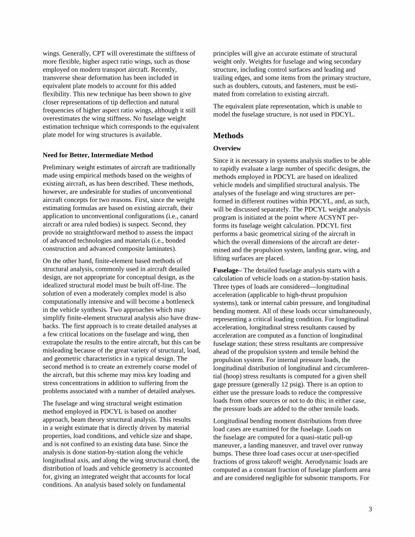
For the transports in the present study, all the fuel iscarried within the wing structure. An option is alsoavailable to carry the fuel entirely within the fuselage,negating any bending relief in the wing. (The highaltitude drone, described in Appendix B, was modeledwith a fuselage fuel tank.) The volume of the trapezoidalplanform, rectangular-section wing box structure (includ-ing the carrythrough structure) is found as follows:
9
V Z y t y dy C C R C w
C C
Cy
bC C
R Cy
bR C R C dy
C
W S
b
S S t R C
S S S
RS
R T
b
t RS
t R t T
S
S
R
S
R R T
= ( ) ( ) + − −( )
= ( ) − −( )
× − −( )
× − −( )
+ − −
∫
∫
2 1
2 1
1
0
2
0
1 2
1 2
1
cos Λ
CC R C w
b C C
R C C C R C C C
C C R C w
S t R C
S S S S
t R R T t T R T
S S t R C
R
R T
R
2
1 2
1 2
2
2
1
3
2 2
1
( )
=− −( ) ( )
× +( ) + +( )[ ]+ − −( )
cos Λ
(33)
This equation is based on flat upper and lower surfacesand neglects the volume taken up by the structure.
Loads
Fuselage– Fuselage loading is determined on a station-by-station basis along the length of the vehicle. Threetypes of fuselage loads are considered—longitudinalacceleration, tank pressure, and bending moment. In thepresent study, all three load types are assumed to occursimultaneously to determine maximum compressive andtensile loads at the outer shell fibers at each station.
Bending loads applied to the vehicle fuselage are obtainedby simulating vehicle pitch-plane motion during a quasi-static pull-up maneuver; a landing; and movement over arunway bump. Simplified vehicle loading models areused where it is assumed that: (1) fuselage lift forces(nominally zero for subsonic transports) are distributeduniformly over the fuselage plan area; (2) wing loading,determined independently, is transferred by a couple ofvertical force and torque through the wing carrythroughstructure; (3) fuselage weight is distributed uniformlyover fuselage volume; (4) control surface forces andlanding gear reactions are point loads; and (5) the pro-pulsion system weight, if mounted on the fuselage, isuniformly distributed. A factor of safety (nominally 1.5)is applied to each load case. The aircraft weight for eachcase is selected as a fraction of gross takeoff weight. Theresulting one-dimensional loading model is shown in
figure 4. All fuselage lift forces are assumed to be linearfunctions of angle of attack. Longitudinal bendingmoments are computed for each of the three loading casesand the envelope of the maximum values taken as thedesign loading condition. The bending moment computa-tion is given in detail in reference 4 and will only besummarized here.
Considering first the pull-up maneuver loading, themotion is assumed to be a quasi-static pitch-plane pull-upof given normal load factor n (nominally 2.5 for transportaircraft). The vehicle is trimmed with the appropriatecontrol surface (a horizontal tail for all eight transportused for validation in the present study), after which theangle of attack is calculated.
Landing loads are developed as the aircraft descends at agiven vertical speed, VS, after which it impacts theground; thereafter the main and nose landing gears areassumed to exert a constant, or optionally a (1 – cos(ωt)),force during its stroke, SLG, until the aircraft comes torest. The vehicle weight is set equal to the nominallanding weight. Wing lift as a fraction of landing weightis specified, which reduces the effective load the landinggear carries. Likewise, the portion of total vehicle loadthe main gear carries is specified. No pitch-plane motionis considered during the landing.
Runway bump loads are handled by inputting the bumpload factor into the landing gear. Bump load factor isapplied according to reference 7. This simulates thevehicle running over a bump during taxi. In a similarfashion to the landing, the wing lift as a fraction of grosstakeoff weight is specified, as is the portion of effectiveload input through the main gear. No pitch-plane motionis considered during the bump.
Wing– For the wing, only a quasi-static pull-up maneuvercondition at load factor n is considered for determiningloads. At each spanwise station along the quarter chord,from the wingtip to the wing-fuselage intersection, the liftload, center of pressure, inertia load, center of gravity,shear force, and bending moment are computed. For theinertia load, it is assumed that the fuel weight WFT isdistributed uniformly with respect to the wing volume sothat the inertial load at y is (WFT/VW)*V(y), where V(y) isthe volume outboard of y; this volume has centroid Cg(y)with respect to station y. An estimate of the wing struc-tural weight is included in WFT for this calculation but thecalculation is not redone when the actual structural weighthas been computed.
There is an option for either a trapezoidal or a Schrenk(ref. 8) lift load distribution along the wingspan; thetrapezoidal distribution represents a uniform lift over thewing area (which has a trapezoidal planform) while the

10
Fuselage Weight
Wing Weight
Tail Weight
Tail Lift
Fuselage Lift
Wing LiftGear Reactions
Gear Weights
Figure 4. Loading model.
Schrenk distribution is an average of the trapezoidaldistribution with an elliptical distribution, where the lift iszero at the wingtip and maximum at the wing-fuselageintersection. Prandtl has shown that a true elliptical liftload distribution will have a minimum induced drag, but acombination of the elliptical and trapezoidal distributionswill give a better representation of actual aircraft loading(ref. 8).
Plots of trapezoidal and Schrenk lift load distributions areshown in figure 5. For the trapezoidal lift load distributionthe lift load at y is (W/S)ATRAP (y), where ATRAP(y) is thearea outboard of y; the centroid of this area is denotedCPTRAP(y), where y is measured along the quarter chord.For the elliptical lift load distribution, the lift loadmatches the contour of an ellipse with the end of its majoraxis on the tip and the end of its minor axis directly abovethe wing-fuselage intersection. The area enclosed by thequadrant of the ellipse is set equal to the exposed area ofthe trapezoidal wing panel
Sb w
R CELLC
TAP R=−( )
+( )4
1 (34)
Thus the value of lift at y, LELL, the area of ellipseoutboard of y, AELL, and the center of pressure of liftoutboard of y, CPELL, for y measured along the structuralbox may be determined as
L yS
b
y
bELLELL
S S( ) = −
41
212
π(35)
A y S
S
by b y b
y
b
ELL ELL
ELL
SS S
S
( ) =
− −( ) +
−2
22 2 2 1
12
πsin
(36)
C y b yP SELL ( ) = −( )4
3π(37)
respectively.

11
Elliptical
Schrenk
Trapezoidal
Fuselage
Wing
Figure 5. Trapezoidal and Schrenk lift load distributions.
For the Schrenk lift load distribution, the average ofATRAP(y) and AELL(y) is used to represent the compositearea, while the average of CPTRAP(y) and CPELL(y) isused to represent the composite center of pressure.
Using the appropriate outboard area A(y) and center ofpressure CP(y), the shear force is
F y nKW
SA
W
VV
h y y W h y y W
S SFT
W
e e e
i
n
i
n
i i i i
e
( ) = −
− −( ) − −( )
==
∑∑ lg lg lg
11
lg
(38)
where ne and nlg are the number of engines and landinggear mounted on the semispan, respectively; Wei and Wlgiare the weights of the ith engine an ith landing gear,respectively; yei and ylgi
are the locations of the ith engineand ith landing gear, respectively; and
h y yy y
y ye e
e
ei
i
i
−( ) =>
<
1
0
,
,(39)
h y yy y
y yi
i
i
lg lg
lg
lg−( ) =
>
<
1
0
,
,(40)
The bending moment is
M y nKW
SAC
W
VVC
h y y W y y
h y y W y y
S PFT
Wg
e
i
n
e e e
i
n
e
i i i
i i i
( ) = −
− −( ) −( )
− −( ) −( )
=
=
∑
∑
1
1
lg lg lg lg
lg
(41)
Structural Analysis
Fuselage– Weight estimating relationships are nowdeveloped for the load-carrying fuselage structure. Inaddition, the volume taken up by the fuselage structure isalso determined.

12
Considering first the circular shell, the stress resultants inthe axial direction caused by longitudinal bending, axialacceleration, and pressure at a fuselage station x are
NMr
Ixy
B=
′(42)
NN W
Pxx S
A= (43)
NAP
Pxg
P= (44)
respectively, where r = D/2 is the fuselage radius, A = πr2
is the fuselage cross-sectional area, and P = 2πr is thefuselage perimeter. In equation 42, ′ =I ry π 3
is the
moment of inertia of the shell divided by the shell thick-ness. In equation 43, for the case of fuselage-mountedpropulsion, Ws is the portion of vehicle weight ahead ofstation x if x is ahead of the inlet entrance, or the portionof vehicle weight behind x if x is behind the nozzle exit.In equation 44, Pg is the limit gage pressure differentialfor the passenger compartment during cruise. The totaltension stress resultant is then
N N Nx x xB P+ = + (45)
if x is ahead of the nozzle exit, and
N N N Nx x x xB P A+ = + + (46)
if x is behind it. Similarly, the total compressive stressresultant is
N N NN
x x xx
B AP
− = + −
0,
,
if not pressure stabilized
if stabilized
(47)
if x is ahead of the inlet entrance, and
N NN
x xx
BP
− = −
0,
,
if not pressure stabilized
if stabilized(48)
if x is behind it. These relations are based on the premisethat acceleration loads never decrease stress resultants,but pressure loads may relieve stress, if pressure stabiliza-tion is chosen as an option. The stress resultant in thehoop direction is
N rP Ky g P= (49)
where Kp accounts for the fact that not all of the shellmaterial (for example, the core material in sandwichdesigns) is available for resisting hoop stress.
The equivalent isotropic thicknesses of the shell are givenby
tN
FSx
cyC
=−
(50)
tF
N NStu
x yT= ( )+1
max , (51)
t K tS mg mgG= (52)
for designs limited by compressive yield strength (Fcy),ultimate tensile strength (Ftu), and minimum gage,respectively. In equation 52, tmg is a specified minimummaterial thickness and Kmg is a parameter relating tSG
totmg which depends on the shell geometry.
A fourth thickness that must be considered is that forbuckling critical designs, tSB
, which will now bedeveloped. The nominal vehicles of this study haveintegrally stiffened shells stabilized by ring frames. In thebuckling analysis of these structures, the shell is analyzedas a wide column and the frames are sized by the Shanleycriteria (ref. 6). Expressions are derived for the equivalentisotropic thickness of the shell required to precludebuckling, tSB
, and for the smeared equivalent isotropicthickness of the ring frames required to preclude generalinstability, tF . The analysis will be restricted to the caseof cylindrical shells. The major assumptions are that thestructural shell behaves as an Euler beam and that allstructural materials behave elastically.
For the stiffened shell with frames concept, the commonprocedure of assuming the shell to be a wide column isadopted. If the frame spacing is defined as d and Young’smodulus of the shell material is defined as E, the bucklingequation is then
N
dE
t
dx SB−
=
ε
2
(53)
or, solving for tSB
tN d
ESx
B=
−
ε(54)
Fuselage structural geometry concepts are presented intable 1; values of the shell efficiency ε for the variousstructural concepts are given in table 2. The structuralshell geometries available are simply stiffened,Z-stiffened, and truss-core sandwich. We next size theframes to prevent general instability failure. The Shanleycriterion is based on the premise that the frames act aselastic supports for the wide column; this criterion givesthe smeared equivalent thickness of the frames as

13
Table 1. Fuselage structural geometry concepts
KCON setsconcept number
2 Simply stiffened shell, frames, sized for minimum weight in buckling
3 Z-stiffened shell, frames, best buckling
4 Z-stiffened shell, frames, buckling-minimum gage compromise
5 Z-stiffened shell, frames, buckling-pressure compromise
6 Truss-core sandwich, frames, bestis, no frames, best buckling
9 Truss-core sandwich, no frames, buckling-minimum gage-pressure compromise
Table 2. Fuselage structural geometry parameters
Structural concept(KCON)
m ε Kmg Kp Kth
2 2 0.656 2.463 2.463 0.0
3 2 0.911 2.475 2.475 0.0
4 2 0.760 2.039 1.835 0.0
5 2 0.760 2.628 1.576 0.0
6 2 0.605 4.310 3.965 0.459
8 1.667 0.4423 4.820 3.132 0.405
9 1.667 0.3615 3.413 3.413 0.320
t rC N
K d EF
F x
F FB
=−
2 2
13
π(55)
where CF is Shanley’s constant, KF1 is a frame geometryparameter, and EF is Young’s modulus for the framematerial. (See ref. 3 for a discussion of the applicability ofthis criterion and for a detailed derivation of the equationspresented here.) If the structure is buckling critical, thetotal thickness is
t t tS FB B= + (56)
Minimizing t with respect to d results in
tC
K E E
r NF
F F
F x=
( )
−4
27
2
1 41
3 3
2 218
14
/πε
ρ
ρ(57)
t tSB= 3
4(58)
t tFB= 1
4(59)
d rC E
K EF F
F F=
6 2
1
12ρ
ρπ ε
(60)
where ρF is the density of the frame material and ρ is thedensity of the shell material, so that the shell is threetimes as heavy as the frames.
Frameless sandwich shell concepts may also be used.For these concepts, it is assumed that the elliptical shellbuckles at the load determined by the maximum compres-sive stress resultant Nx
− on the cylinder. The bucklingequation for these frameless sandwich shell concepts is
N
rE
t
rx S
mB
−=
ε (61)
where m is the buckling equation exponent. Or, solvingfor tSB

14
t rN
rESx
B
m=
−
ε
1
(62)
This equation is based on small deflection theory, whichseems reasonable for sandwich cylindrical shells,although it is known to be inaccurate for monocoquecylinders. Values of m and ε may be found, for examplein references 9 and 10 for many shell geometries. Table 2gives values for sandwich structural concepts available inPDCYL, numbers 8 and 9, both of which are truss-coresandwich. The quantities Nx
− , r, and consequently tSB,
will vary with fuselage station dimension x.
At each fuselage station x, the shell must satisfy all failurecriteria and meet all geometric constraints. Thus, the shellthickness is selected according to compression, tension,minimum gage, and buckling criteria, or
t t t t tS S S S SC T G B= ( )max , , , (63)
If t tS SB= , the structure is buckling critical and the
equivalent isotropic thickness of the frames, tF , iscomputed from equation 59. If t tS SB> , the structure isnot buckling critical at the optimum frame sizing and theframes are resized to make t tS SB= . Specifically, a newframe spacing is computed from equation 54 as
dE t
NS
x= −
ε 2(64)
and this value is used in equation 55 to determine tF .
The total thickness of the fuselage structure is then givenby the summation of the smeared weights of the shell andthe frames
t t tB S F= + (65)
The shell gage thickness may be computed fromt t Kg S mg= / . The ideal fuselage structural weight isobtained by summation over the vehicle length
W t t r xI S F F i ii i= +( )∑2π ρ ρ ∆ (66)
where the quantities subscripted i depend on x.
We next discuss the derivation of the structural geometryparameters shown in table 2. The Z-stiffened shell, typicalof modern transport aircraft, will be used as an exampleof skin-stringer-frame construction. Using reference 9 andfigure 6, the equivalent isotropic thickness of the smearedskin and stringers is
t tb f
b
b t
b
b
b
t
ttS s
f f
s
w w
s
w
s
w
ss= + + = +
21 1 6. (67)
Since only the skin is available for resisting pressureloads,
Kb
b
t
tpw
s
w
w= +
1 1 6. (68)
For minimum gage designs, if ts > tw then tw = tmg and
tt
t
b
btS
s
w
w
smg=
+
1 6. (69)
so that
Kt
t
b
bmgs
w
w
s=
+
1 6. (70)
On the other hand, if ts < tw then ts = tmg and
tb
b
t
ttS
w
s
w
smg= +
1 1 6. (71)
so that
Kb
b
t
tmgw
s
w
s= +
1 1 6. (72)
Equations 68, 70, and 72 show that for both pressureloading critical and minimum gage limited structure,(bw/bs) and (tw/ts) should be as small as possible (i.e.,no stringers). As an option in PDCYL, all of the detailedshell dimensions shown in figure 6 are computed andoutput at each fuselage station.
In practice, a typical design will be influenced by bendingand pressure loads and by the minimum gage constraint,and thus a compromise is necessary. If buckling isof paramount importance, then a good choice is(bw/bs) = 0.87 and (tw/ts) = 1.06 because this gives themaximum buckling efficiency for this concept, namelyε = 0.911 (ref. 9). From equations 68 and 72,
K Kp mg= = + ( )( )( ) =1 1 6 0 87 1 06 2 475. . . . (73)
This is concept 3 in tables 1 and 2. If pressure dominatesthe loading condition, then (bw/bs) = 0.6 and (tw/ts)=0.6is a reasonable choice, giving ε = 0.76, Kp = 1.576, andKmg = 2.628; this is concept 5. For minimum gagedominated structure, the geometry (bw/bs) = 0.58 and(tw/ts) = 0.90 gives concept 6.

15
0.3bw
0.3bw
ts
bw
twbs
tw
tw
Figure 6. Typical Z-stiffened shell geometry.
tfbf
h
R
ψtc
Figure 7. Truss-core sandwich geometry.
The geometry of the truss-core sandwich shell conceptis shown in figure 7. The equivalent isotropic shellthickness of this concept is
tt
ttS
c
ff= + ( )
2
1
cos ψ(74)
Reference 9 shows that the optimum buckling efficiencyis obtained for (tc/tf) = 0.65 and ψ = 55 deg. This gives
ε = 0.4423, Kmg = 4.820, and Kp = 3.132, concept 8 in
tables 1 and 2. To get a design that is lighter for minimumgage dominant structure, a geometry is chosen that placesequal thickness material in the face sheets and the core;the choice of (tc/tf) = 1.0 and ψ = 45 deg gives structuralconcept 9. These calculations assume that the face sheetsand core are composed of the same material and aresubject to the same minimum gage constraint.
16
Since the preceding analysis gives only the ideal weight,WI, the nonoptimum weight, WNO (including fasteners,cutouts, surface attachments, uniform gage penalties,manufacturing constraints, etc.) has yet to be determined.The method used will be explained in a later section.
Wing– Using the geometry and loads applied to the wingdeveloped above, the structural dimensions and weight ofthe structural box may now be calculated. The wing struc-ture is assumed to be a rectangular multi-web box beamwith the webs running in the direction of the structuralsemispan. Reference 9 indicates that the critical instabilitymode for multi-web box beams is simultaneous bucklingof the covers due to local instability and of the webs dueto flexure induced crushing. This reference gives thesolidity (ratio of volume of structural material to totalwing box volume) of the least weight multi-web boxbeams as
Σ =
ε M
Z t ES
e
2 (75)
where ε and e depend on the cover and web geometries(table 3), M is the applied moment, t is the thickness, E isthe elastic modulus, and ZS is obtained from reference 9.The solidity is therefore
Σ =′ ( )W y
Z tBEND
Sρ(76)
where ′WBEND is the weight of bending material per unitspan and ρ is the material density. ′WBEND is computedfrom equations 75 and 76. The weight per unit span of theshear material is
′ ( ) =W yF
SHEARS
S
ρσ
(77)
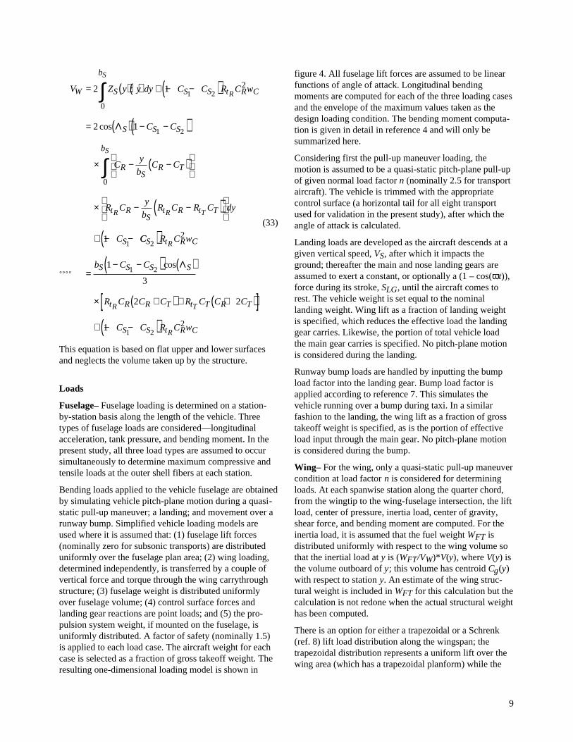
where FS is the applied shear load and σS is the allowableshear stress. The optimum web spacing (fig. 8) is com-puted from (ref. 2)
d te
e
M
Z t EW
C
C W S
e
eC
e
eC
C eC
C
C
=−( )
−( )
− −1 2
1 2 2
2 3
2
2
4 33
2ε
ε
(78)
where subscripts W and C refer to webs and covers,respectively. The equivalent isotropic thicknesses of thecovers and webs are
t dM
Z tE dC WS C W
eC−
ε
1
(79)
t tM
Z t E
d
tWS
e C W e
W
C C=
−
2
21 1
2εε
(80)
respectively, and the gage thicknesses are
t K tg g CC C= (81)
t K tg g WW W= (82)
Values of ε, e, εC, EC, εW, Kgw, and Kgc are found intable 3 for various structural concepts (ref. 9). If the wingstructural semispan is divided into N equal length seg-ments, the total ideal weight of the wing box structure is
Wb
NW WBOX
SBEND SHEAR
i
N
i i= ′ + ′( )
=∑2
1
(83)
Table 3. Wing structural coefficients and exponents
Covers Webs ε e ε ec εw Kgc Kgw
Unstiffened Truss 2.25 0.556 3.62 3 0.605 1.000 0.407
Unstiffened Unflanged 2.21 0.556 3.62 3 0.656 1.000 0.505
Unstiffened Z-stiffened 2.05 0.556 3.62 3 0.911 1.000 0.405
Truss Truss 2.44 0.600 1.108 2 0.605 0.546 0.407
Truss Unflanged 2.40 0.600 1.108 2 0.656 0.546 0.505
Truss Z-stiffened 2.25 0.600 1.108 2 0.911 0.546 0.405

17
dw
tgw
tgc
Figure 8. Wing structural concept.
The wing carrythrough structure consists of torsionmaterial in addition to bending and shear material. Thetorsion material is required to resist the twist induceddue to the sweep of the wing. The bending material iscomputed in a similar manner as that of the box exceptthat only the longitudinal component of the bendingmoment contributes. Letting t0 = t(y = 0) andM0 = M(y = 0),
Σ εΛ
CS
SR
eM
t C E=
( )
0
02cos
(84)
The weight of the bending material is then
W C t wBEND C SR CC= ρΣ 0 (85)
where wC is the width of the carrythrough structure.(When the wing-fuselage intersection occurs entirelywithin the cylindrical midsection, as is the case with alleight transport used for validation in the present study,wC = D.) The quantities dW, tW, and tC are computed in
the same manner as for the box. The weight of the shearmaterial is
WF
wSHEARS
SCC
= ρσ
0 (86)
where FS0 = FS(0).
The torque on the carrythrough structure is
T M S= ( )0 sin Λ (87)
and the weight of the torsion material is then
WT t C w
t CTORSIONSR C
SR SC
=+( )ρ
σ0
0(88)
Finally, the ideal weight of the carrythrough structure iscomputed from a summation of the bending shear andtorsion material, or
W W W WC BEND SHEAR TORSIONC C C= + + (89)

18
As in the case of the fuselage structural weight, nonopti-mum weight must be added to the ideal weight to obtainthe true wing structural weight. The method used will bediscussed below.
The static deflection of the wingtip under the pull-upmaneuver is also determined. Using the moment-areamethod applied to an Euler beam (ref. 11), the deviationof point B on the deflected surface from the tangentdrawn from another point A on the surface is equal to thearea under the M/(EI) diagram between A and B multi-plied by the distance to the centroid of this area from B,
t ydM
EIydyBA
B
A
B
A
= =∫ ∫θ (90)
where θ is the angular displacement of the beam and y isthe longitudinal axis of the beam. For the case of a wingwith trapezoidal planform, the longitudinal axis, y, will liealong the quarter-chord line (fig. 3). For a wing with ahorizontal unloaded configuration, the tangential devia-tion, tBA, will equal the true vertical tip displacement(assumed to be the case). Only the wing cover contributesto the bending resistance, while the webs offer similarshear stiffness. The wing area moment of inertia, I, atany structural semispan station y is determined with theParallel Axis theorem, as cover thickness is small whencompared with total wing thickness.
Regression Analysis
Overview– Using fuselage and wing weight statementsof eight subsonic transports, a relation between the calcu-lated load-bearing structure weights obtained throughPDCYL and the actual load-bearing structure weights,primary structure weights, and total weights is determinedusing statistical analysis techniques. A basic applicationwhich is first described is linear regression, wherein theestimated weights of the aircraft are related to the weightscalculated by PDCYL with a straight line, y = mx + b,where y is the value of the estimated weight, m is theslope of the line, x is the value obtained through PDCYL,and b is the y-intercept. This line is termed a regressionline, and is found by using the method of least squares,in which the sum of the squares of the residual errorsbetween actual data points and the corresponding pointson the regression line is minimized. Effectively, a straightline is drawn through a set of ordered pairs of data (inthis case eight weights obtained through PDCYL and thecorresponding actual weights) so that the aggregatedeviation of the actual weights above or below this line isminimized. The estimated weight is therefore dependentupon the independent PDCYL weight.
As an example, if the form of the regression equation islinear, the estimated weight is
y mx best calc= + (91)
where m is the slope, b is the intercept, and xcalc is theweight PDCYL calculates. The resulting residual to beminimized is
E y yactual est
i
n
i i= −( )
=∑ 2
1
(92)
or
E y mx bactual calc
i
n
i i= − −( )
=∑ 2
1
(93)
where yactual is the actual component weight and n is thenumber of aircraft whose data are to be used in the fit. Bytaking partial derivatives of the residual error with respectto both m and b, equations for the values of these twounknown variables are found to be
m
n x y x y
n x x
calc act calc act
i
n
i
n
i
n
calc calc
i
n
i
n
i i i i
i i
=
−
−
===
==
∑∑∑
∑∑111
2
1
2
1
(94)
b y nx x y x yact calc= − =, mean values of and (95)
Of key importance is the degree of accuracy to which theprediction techniques are able to estimate actual aircraftweight. A measure of this accuracy, the correlationcoefficient, denoted R, represents the reduction in residualerror due to the regression technique. R is defined as
RE E
Et r
r= −
(96)
where Et and Er refer to the residual errors associatedwith the regression before and after analysis is performed,respectively. A value of R = 1 denotes a perfect fit of thedata with the regression line. Conversely, a value of R = 0denotes no improvement in the data fit due to regressionanalysis.
There are two basic forms of equations which areimplemented in this study. The first is of the form
y mxest calc= (97)
The second general form is
y mxest calca= (98)

19
The first form is a simplified version of the linearexample as discussed above, with the y-intercept term setto zero. However, because the second general equation isnot linear, nor can it be transformed to a linear equation,an alternative method must be employed. In order toformulate the resulting power-intercept regression equa-tion, an iterative approach developed by D. W. Marquardtis utilized (ref. 12). This algorithm starts at a certain pointin space, and, by applying the method of steepest descent,a gradient is obtained which indicates the direction inwhich the most rapid decrease in the residual errors willoccur. In addition, the Taylor Series method produces asecond similar vector. Interpolation between these twovectors yields a direction in which to move the point inorder to minimize the associated error. After severaliterations, the process converges to a minimum value. Itshould be noted that there may be several local minimumsand there is no guarantee that the method converges to theglobal one.
Fuselage– The analysis above is used to develop arelationship between weight calculated by PDCYL andactual wing and fuselage weights. The data were obtainedfrom detailed weight breakdowns of eight transport air-craft (refs. 13–17) and are shown in table 4 for thefuselage. Because the theory used in the PDCYL analysisonly predicts the load-carrying structure of the aircraftcomponents, a correlation between the predicted weightand the actual load-carrying structural weight and primaryweight, as well as the total weight of the fuselage, wasmade.
Structural weight consists of all load-carrying membersincluding bulkheads and frames, minor frames, covering,covering stiffeners, and longerons. For the linear curve-fit, the resulting regression equation is
W W Ractual calc= =1 3503 0 9946. . (99)
This shows that the nonoptimum factor for fuselagestructure is 1.3503; in other words, the calculated weightmust be increased by about 35 percent to get the actualstructural weight. For the alternative power-interceptcurve fitting analysis, the resulting load-carryingregression equation is
W W Ractual calc= =1 1304 0 99461 0179. .. (100)
To use either of these equations to estimate total fuselageweight, nonstructural weight items must be estimatedindependently and added to the structural weight.
Primary weight consists of all load-carrying members aswell as any secondary structural items such as jointsfasteners, keel beam, fail-safe straps, flooring, flooringstructural supplies, and pressure web. It also includes thelavatory structure, galley support, partitions, shear ties, tierods, structural firewall, torque boxes, and attachmentfittings. The linear curve fit for this weight yields thefollowing primary regression equation
W W Ractual calc= =1 8872 0 9917. . (101)
The primary power-intercept regression equation is
W W Ractual calc= =1 6399 0 99171 0141. .. (102)
Table 4. Fuselage weight breakdowns for eight transport aircraft
Weight, lb
Aircraft PDCYL Load-carrying structure Primary structure Total structure
B-720 6545 9013 13336 19383
B-727 5888 8790 12424 17586
B-737 3428 5089 7435 11831
B-747 28039 39936 55207 72659
DC-8 9527 13312 18584 24886
MD-11 20915 25970 34999 54936
MD-83 7443 9410 11880 16432
L-1011 21608 28352 41804 52329

20
The total fuselage weight accounts for all members of thebody, including the structural weight and primary weight.It does not include passenger accommodations, such asseats, lavatories, kitchens, stowage, and lighting; theelectrical system; flight and navigation systems; alightinggear; fuel and propulsion systems; hydraulic and pneu-matic systems; the communication system; cargo accom-modations; flight deck accommodations; air conditioningequipment; the auxiliary power system; and emergencysystems. Linear regression results in the following totalfuselage weight equation
W W Ractual calc= =2 5686 0 9944. . (103)
This shows that the nonoptimum factor for the totalfuselage weight is 2.5686; in other words, the fuselage
structure weight estimated by PDCYL must be increasedby about 157 percent to get the actual total fuselageweight. This nonoptimum factor is used to comparefuselage structure weight estimates from PDCYL withtotal fuselage weight estimates from the Sanders and theAir Force equations used by ACSYNT.
The total fuselage weight power-intercept regressionequation is
W W Ractual calc= =3 9089 0 99490 9578. .. (104)
Plots of actual fuselage component weight versusPDCYL-calculated weight, as well as the correspondinglinear regressions, are shown in figures 9–11.
5000
10000
15000
20000
25000
30000
35000
40000
0 5000 10000 15000 20000 25000 30000
Act
ual
Load
Car
ying
Wei
ght
747
737
727
720
MD-83
DC-8
MD-11
L-1011Wactual = 1.3503 WPDCYL
Figure 9. Fuselage load-carrying structure and linear regression.

21
0
10000
20000
30000
40000
50000
60000
0 5000 10000 15000 20000 25000 30000
Act
ual P
rimar
y F
usel
age
Wei
ght
747
737
727
720
MD-83
DC-8
MD-11
L-1011
Wactual = 1.8872 WPDCYL
Figure 10. Fuselage primary structure and linear regression.
10000
20000
30000
40000
50000
60000
70000
80000
0 5000 10000 15000 20000 25000 30000
Act
ual F
usel
age
Tot
al W
eigh
t
747
737
727
720
MD-83
DC-8
MD-11
L-1011Wactual = 2.5686 WPDCYL
Figure 11. Fuselage total structure and linear regression.
22
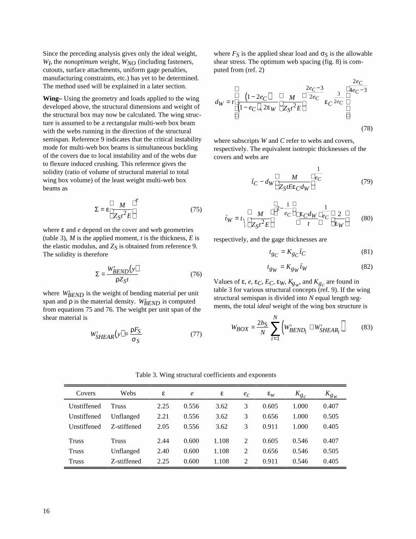
Table 5. Wing weight breakdowns for eight transport aircraft
Weight, lb
Aircraft PDCYL Load-carrying structure Primary structure Total structure
B-720 13962 11747 18914 23528
B-727 8688 8791 12388 17860
B-737 5717 5414 7671 10687
B-747 52950 50395 68761 88202
DC-8 22080 19130 27924 35330
MD-11 33617 35157 47614 62985
MD-83 6953 8720 11553 15839
L-1011 25034 28355 36101 46233
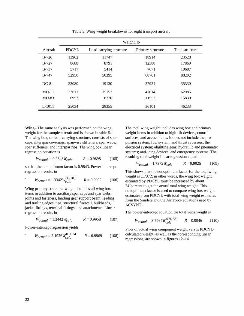
Wing– The same analysis was performed on the wingweight for the sample aircraft and is shown in table 5.The wing box, or load-carrying structure, consists of sparcaps, interspar coverings, spanwise stiffeners, spar webs,spar stiffeners, and interspar ribs. The wing box linearregression equation is
W W Ractual calc= =0 9843 0 9898. . (105)
so that the nonoptimum factor is 0.9843. Power-interceptregression results in
W W Ractual calc= =1 3342 0 99020 9701. .. (106)
Wing primary structural weight includes all wing boxitems in addition to auxiliary spar caps and spar webs,joints and fasteners, landing gear support beam, leadingand trailing edges, tips, structural firewall, bulkheads,jacket fittings, terminal fittings, and attachments. Linearregression results in
W W Ractual calc= =1 3442 0 9958. . (107)
Power-intercept regression yields
W W Ractual calc= =2 1926 0 99690 9534. .. (108)
The total wing weight includes wing box and primaryweight items in addition to high-lift devices, controlsurfaces, and access items. It does not include the pro-pulsion system, fuel system, and thrust reversers; theelectrical system; alighting gear; hydraulic and pneumaticsystems; anti-icing devices; and emergency systems. Theresulting total weight linear regression equation is
W W Ractual calc= =1 7372 0 9925. . (109)
This shows that the nonoptimum factor for the total wingweight is 1.7372; in other words, the wing box weightestimated by PDCYL must be increased by about74 percent to get the actual total wing weight. Thisnonoptimum factor is used to compare wing box weightestimates from PDCYL with total wing weight estimatesfrom the Sanders and the Air Force equations used byACSYNT.
The power-intercept equation for total wing weight is
W W Ractual calc= =3 7464 0 99460 9268. .. (110)
Plots of actual wing component weight versus PDCYL-calculated weight, as well as the corresponding linearregressions, are shown in figures 12–14.

23
0
10000
20000
30000
40000
50000
60000
0 10000 20000 30000 40000 50000 60000
Act
ual
Win
g B
ox W
eigh
t
747
737727
MD-83720
DC-8
L-1011
MD-11Wactual = 0.9843 WPDCYL
Figure 12. Wing load-carrying structure and linear regression.
0
10000
20000
30000
40000
50000
60000
70000
0 10000 20000 30000 40000 50000 60000
Act
ual P
rimar
y W
ing
Wei
ght
747
737
MD-83727
720
DC-8
L-1011
MD-11
Wactual = 1.3442 WPDCYL
Figure 13. Wing primary structure and linear regression.

24
10000
20000
30000
40000
50000
60000
70000
80000
90000
0 10000 20000 30000 40000 50000 60000
Act
ual T
otal
Win
g W
eigh
t747
737
MD-83727 720
DC-8
L-1011
MD-11
Wactual = 1.7372 WPDCYL
Figure 14. Wing total structure and linear regression.
Discussion– Both fuselage and wing weight linear andpower regressions give excellent correlation with therespective weights of existing aircraft, as evidenced bythe high values of the correlation coefficient, R. It shouldbe noted that even though the power-based regressionsgive correlations equal to or better than the linear regres-sions their factors may vary distinctly from the linearcases. This is due to their powers not equaling unity.
Because estimates of non-load-bearing primary structureare generally not available at the conceptual design stage,and because nonprimary structure is probably not wellestimated by a nonoptimum factor, equations 101 and 107are recommended for estimating the primary structuralweights of the respective transport fuselage and wingstructures (figs. 10 and 13).

25
Appendix A – User’s Manual, Example
Description
The purpose of this appendix is to give a detailed exampleof the input procedure used to allow PDCYL to calculatefuselage and wing weights for a sample transport aircraftduring an ACSYNT run. A sample output from PDCYLwill also be given. The Boeing 747-21P will be used forthe example. The layout of the 747-21P is shown infigure 15. The weights of the load-carrying portions of thefuselage and wing box for the 747-21P will be calculatedby PDCYL and scaled by the respective nonoptimumfactors developed earlier to give estimates for the weightsof the fuselage and wing. A comparison between methodscurrently used by ACSYNT to estimate fuselage and wingweights and PDCYL output will be made with thecorresponding actual weights of the 747-21P.
Input
PDCYL requires input from both the existing ACSYNTdata structure and an additional namelist containing datarequired by PDCYL which are not contained within thecurrent ACSYNT format. There are three steps to runPDCYL within ACSYNT. First, the aircraft type isspecified in the ACSYNT Control input. Currently theTransport Aircraft type is used. Second, data withinACSYNT module namelists are required. The ACSYNTGeometry, Trajectory, and Weights modules supply datafor PDCYL execution. PDCYL uses the WING, HTAIL,VTAIL, FUS, WPOD, and FPOD namelists from theGeometry module. From the Trajectory module, theTRDATA namelist is used. From the Weights module theOPTS namelist is used. Third, data from the PDCYLINnamelist are used.
Variables used from ACSYNT namelists and thePDCYLIN namelist are given in tables 6 and 7, respec-tively. Default values for all variables are also given.These default values match the Boeing 747-21P. Keyconfiguration parameters are given for each of the eightaircraft used in the validation study in table 8. Anexample of the PDCYLIN namelist input for the 747-21Pis shown in figure 16.
A description of the specific structural concepts used tomodel both the fuselage and wing is given in the Struc-tural Analysis section. As was noted earlier, the typicalmodern transport aircraft fuselage is a Z-stiffened shell.The buckling-minimum material gage compromise was
employed because it gives the lowest-weight (optimal)structure for the eight aircraft investigated in this study.
Output
PDCYL weights output begins with the wing box andcarrythrough structure analysis. The wing is sized duringa quasi-static pull-up maneuver where the load factor isset equal to the ultimate load factor (nominally 3.75).Wing output contains three parts. First is the overallgeometrical configuration. Second is a detailed station-by-station bending, shear, and torsion analysis andcorresponding geometrical sizing along the span. Thirdis the detailed geometrical layout, loading, and weightbreakdown of the carrythrough structure, weight break-down of the wing components, and deflection of thewingtip. This wing weight is multiplied by the nonopti-mum factor and returned to ACSYNT. An example of thePDCYL wing weight output for the 747-21P is shown infigure 17.
Next, the fuselage is analyzed. Fuselage output containsfour parts. First is the overall geometrical layout andweight breakdown. Second is a station-by-station bend-ing, shear, and axial stress analysis. Up to three load casesare investigated. In order they are a quasi-static pull-upmaneuver, a landing maneuver, and travel over runwaybumps. Third, the envelope of worst-case loading isshown for each station, from which the shell and framesare sized. Corresponding unit weight breakdowns are alsogiven. As an option, the detailed geometric configurationat each station may be output. Fourth, weights summariesare given for the top and bottom sections of the fuselage(nominally the same). These summaries are then averagedto give the weight summary of the entire fuselage. Thefuselage weight, including the corresponding nonopti-mum factor, is returned to ACSYNT. An example of thePDCYL fuselage weight output for the 747-21P is shownin figure 18.
Figure 19(a) shows a comparison between fuselageweight estimates from the Sanders equation, the Air Forceequation, and PDCYL with the actual fuselage weight ofthe 747-21P. Figure 19(b) shows a similar comparison forthe wing weight. SLOPE and TECH factors were set toone for the comparisons in Figures 19(a) and 19(b), whilethe nonoptimum factors are those relating PDCYL esti-mations of structure weight to respective total componentweight.

26

27
Table 6. ACSYNT variables
Variable Type Dimension Description Units/comment Default (747)
1. Geometry module
Namelist WING
SWEEP float 1 Sweep of wing. degrees 37.17
KSWEEP integer 1 1 → Referenced to the leading edge.
2 → Referenced to the quarter chord. 2
3 → Referenced to the trailing edge.
AR float 1 Aspect ratio of wing. 6.96
TAPER float 1 Taper ratio of wing. 0.2646
TCROOT float 1 Thickness-to-chord ratio at the root. 0.1794
TCTIP float 1 Thickness-to-chord ratio at the tip. 0.078
ZROOT float 1 Elevation of MAC above fuselagereference plane, measured as a fractionof the local fuselage radius.
–0.1
AREA float 1 Planform area of wing. ft2 5469
DIHED float 1 Dihedral angle of wing. degrees 7
XWING float 1 Ratio of distance measured from nose toleading edge of wing to total fuselagelength.
0.249
Namelist HTAIL (horizontal tail)
SWEEP float 1 Sweep of tail degrees 34.29
KSWEEP integer 1 1 → Referenced to the leading edge.
2 → Referenced to the quarter chord. 2
3 → Referenced to the trailing edge.
AR float 1 Aspect ratio of the horizontal wing. (span)2/area 3.625
TAPER float 1 Taper ratio of the horizontal wing. tip chord/rootchord
0.25
TCROOT float 1 Thickness-to-chord ratio at the root. 0.11
TCTIP float 1 Thickness-to-chord ratio at the tip. 0.08
ZROOT float 1 Elevation of MAC above fuselagereference plane, measured as a fractionof the local fuselage radius.
0.69
AREA float 1 Planform area of the horizontal wing. ft2 1470
XHTAIL float 1 Position for trailing edge of tail rootchord. If ZROOT ≤ 1, then XHTAIL isgiven as a fraction of body length. Else,XHTAIL is given as a fraction of thelocal vertical tail chord.
1

28
Table 6. Continued
Variable Type Dimension Description Units/comment Default (747)
Namelist VTAIL (vertical tail)
SWEEP float 1 Sweep of vertical tail. degrees 45.73
KSWEEP integer 1 1 → Referenced to the leading edge.
2 → Referenced to the quarter chord. 2
3 → Referenced t the trailing edge.
AR float 1 Aspect ratio of vertical tail. (span)2/area 1.247
TAPER float 1 Taper ratio of vertical tail. tip chord/rootchord
0.34
TCROOT float 1 Thickness-to-chord ratio at root. 0.1298
TCTIP float 1 Thickness-to-chord ratio at tip. 0.089
ZROOT float 1 Elevation of MAC above fuselagereference plane, measured as a fractionof the local fuselage radius.
0.6
AREA float 1 Planform area of vertical tail. ft2 830
Namelist FUS (fuselage)
FRN float 1 Fineness ratio of the nose section. length/diameter 2.13
FRAB float 1 Fineness ratio of after-body section. length/diameter 3.29
BODL float 1 Length of fuselage. ft 225.167
BDMAX float 1 Maximum diameter of fuselage. ft 20.2
Namelist WPOD (wing-mounted propulsion pod)
DIAM float 1 Engine diameter. ft 6.2
LENGTH float 1 Length of engine pod. ft 15
X float 1 X location of nose of pod relative toleading edge of wing, given as afraction of local chord of wing (>0 ifface of pod is behind leading edge ofwing).
–0.631
Y float 1 Y location of center of pod, given as afraction of semispan, measured frombody centerline.
0.241
Z float 1 Z location of center of pod above winglocal chord, given as fraction ofmaximum pod diameter.
–0.83
SWFACT float 1 Wetted area multiplier.

29
Table 6. Concluded
Variable Type Dimension Description Units/comment Default (747)
Namelist FPOD (fuselage-mounted propulsion pod)
DIAM float 1 Engine diameter. ft N/A
LENGTH float 1 Length of engine pod. ft N/A
SOD float 1 Stand-off-distance, the distance from thepod wall to the fuselage wall, given as afraction of maximum pod radius.
N/A
THETA float 1 Angular orientation of pod, THETAmeasured positive up from thehorizontal reference plane.
degrees N/A
X float 1 X location of nose relative to nose offuselage, given as a fraction of bodylength.
N/A
2. Trajectory module
Namelist TRDATA (used for load factors)
DESLF float 1 Design load factor. N/A 2.5
ULTLF float 1 Ultimate load factor, usually 1.5*DESLF. N/A 3.75
3. Weights module
Namelist OPTS
WGTO float 1 Gross take-off weight. lb 713000
WE float 1 Total weight of propulsion system(includes both wing and fuselagemounted engines).
lb 44290

30
Table 7. PDCYL variables
Variable Type Dimension Description Units/comment Default (747)
Namelist PDCYLIN
Wing
Material properties
PS float 1 Plasticity factor. 1
TMGW float 1 Min. gage thickness for the wing inches 0.2
EFFW float 1 Buckling efficiency of the web. 0.656
EFFC float 1 Buckling efficiency of the covers. 1.03
ESW float 1 Young’s Modulus for wing material. psi 1.07E+07
FCSW float 1 Ult. compressive strength of wing. psi 54000
DSW float 1 Density of the wing material. lb/in.3 0.101
KDEW float 1 Knock-down factor for Young's Modulus. 1
KDFW float 1 Knock-down factor for Ultimate strength. 1
Geometric parameters
ISTAMA integer 1 1 → the position of the wing is unknown. 2
2 → the position of the wing is known.
CS1 float 1 Position of structural wing box fromleading edge as percent of root chord.
0.088
CS2 float 1 Position of structural wing box fromtrailing edge as percent of root chord.
0.277
Structural concept
CLAQR float 1 Ratio of body lift to wing lift. For subsonicaircraft
CLAQR ~ 0.0
0.001
IFUEL integer 1 1 → no fuel is stored in the wing. 2
2 → fuel is stored in the wing.
CWMAN float 1 Design maneuver load factor. 1
CF Shanley's const. for frame bending. 6.25E-05
Fuselage
Structural concept
CKF float 1 Frame stiffness coefficient. 5.24
EC float 1 Power in approximation equation forbuckling stability.
2.36
KGC float 1 Buckling coefficient for componentgeneral buckling of stiffener web panel.
0.368
KGW float 1 Buckling coefficient for component localbuckling of web panel.
0.505

31
Table 7. Continued
KCON(T/B) Structural geometry concept Default (747)
2 Simply stiffened shell, frames, sized for minimum weight in buckling
3 Z-stiffened shell, frames, best buckling
4 Z-stiffened shell, frames, buckling-minimum gage compromise
5 Z-stiffened shell, frames, buckling-pressure compromise 4
6 Truss-core sandwich, frames, best buckling
8 Truss-core sandwich, no frames, best buckling
9 Truss-core sandwich, no frames, buckling-min. gage-pressure compromise
Variable Type Dimension Description Units/Comment Default (747)
Material properties
FTS(T/B) float 4 Tensile strength on (top/bottom). psi 58500
FCS(T/B) float 4 Compressive strength. psi 54000
ES(T/B) float 4 Young's Modulus for the shells. psi 1.07E+07
EF(T/B) float 4 Young's Modulus for the frames. psi 1.07E+07
DS(T/B) float 4 Density of shell material on (t/b). lb/in.3 0.101
DF(T/B) float 4 Density of frame material. lb/in.3 0.101
TMG(T/B) float 4 Minimum gage thickness. in. 0.071
KDE float 1 Knock-down factor for modulus. 1
KDF float 1 Knock-down factor for strength. 1
Geometric parameters
CLBR1 float 1 Fuselage break point as a fraction of totalfuselage length.
1.1
ICYL integer 1 1 → modeled with a mid-body cylinder. 1
Else → use two power-law bodies back toback.
Loads
AXAC float 1 Axial acceleration. g’s 0
CMAN float 1 Weight fraction at maneuver. 1
ILOAD integer 1 1 → analyze maneuver only.
2 → analyze maneuver and landing only. 3
3 → analyze bump, landing, andmaneuver.
PG(T/B) float 12 Fuselage gage pressure on (top/bot). psi 13.65
WFBUMP float 1 Weight fraction at bump. 0.001
WFLAND float 1 Weight fraction at landing. 0.9

32
Table 7. Continued
Variable Type Dimension Description Units/Comment Default (747)
Landing gear
VSINK float 1 Design sink velocity at landing. ft/sec 10
STROKE float 1 Stroke of landing gear. ft 2.21
CLRG1 float 1 Length fraction of nose landing gear. 0.1131
CLRG2 float 1 Length fraction of main landing gearmeasured as a fraction of total fuselagelength.
0.466
WFGR1 float 1 Weight fraction of nose landing gear. 0.0047
WFGR2 float 1 Weight fraction of main landing gear. 0.0398
IGEAR integer 1 1 → main landing gear located onfuselage.
2
2 → main landing gear located on wing.
GFRL float 1 Ratio of force taken by nose landing gearto force taken by main gear at landing.
0.001
CLRGW1CLRGW2
floatfloat
11
Position of wing gear as a fraction ofstructural semispan.
If only 1 winggear, set
CLRGW2 = 0.0
0.0640.1844
Tails
ITAIL integer 1 1 → control surfaces mounted on tail. 1
2 → control surfaces mounted on wing.
Weights
WTFF float 1 Weight fraction of fuel. 0.262
CBUM float 1 Weight fraction at bump. 1
CLAN float 1 Weight fraction at landing. 0.791

33
Table 7. Concluded
Variable Type Dimension Description Units/Comment Default (747)
Factors
ISCHRENK integer 1 1 → use Schrenk load distribution onwing.
1
Else → use trapezoidal distribution.
ICOMND integer 1 1 → print gross shell dimensionsenvelope.
1
2 → print detailed shell geometry.
WGNO float 1 Nonoptimal factor for wing (including thesecondary structure).
1
SLFMB float 1 Static load factor for bumps. 1.2
WMIS float 1 Volume component of secondarystructure.
0
WSUR float 1 Surface area component of secondarystructure.
0
WCW float 1 Factor in weight equation for nonoptimalweights.
1
WCA float 1 Factor in weight equation multiplyingsurface areas for nonoptimal weights.
0
NWING integer 1 Number of wing segments for analysis. 40

34
Table 8. Key configuration parameters for eight transport aircraft
Variable 720 727 737 747 DC-8 MD-11 MD-83 L-1011
ACSYNT INPUT PARAMETERS
1. Geometry module
Namelist WING
SWEEP 35 32 25 37.17 30.6 35 24.16 35
KSWEEP 2 2 2 2 2 2 2 2
AR 6.958 7.67 8.21 6.96 7.52 7.5 9.62 6.98
TAPER 0.333 0.2646 0.2197 0.2646 0.1974 0.255 0.156 0.3
TCROOT 0.1551 0.154 0.126 0.1794 0.1256 0.167 0.138 0.13
TCTIP 0.0902 0.09 0.112 0.078 0.105 0.093 0.12 0.09
ZROOT –1 –1 –0.25 –0.1 –1 –0.79 –1 –1
AREA 2460 1587 1005 5469 2927 3648 1270 3590
DIHED 3 3 6 7 3 6 3 3
XWING 0.2963 0.376 0.35 0.249 0.302 0.218 0.468 0.359
Namelist HTAIL
SWEEP 35 31.05 30.298 34.29 35 35.5 30.8 3.5
KSWEEP 2 2 2 2 2 2 2 2
AR 3.15 3.4 4.04 3.625 4.04 3.43 4.88 4
TAPER 0.457 0.383 0.3974 0.25 0.329 0.412 0.357 0.33
TCROOT 0.11 0.11 0.132 0.11 0.095 0.143 0.107 0.095
TCTIP 0.09 0.0894 0.108 0.08 0.08 0.1067 0.08 0.08
ZROOT 0.5 2 0.67 0.69 0.25 0.6875 2 0.5
AREA 500 376 312 1470 559 920 314 1282
XHTAIL 1 0.95 0.8532 0.974 1 0.96 0.98 0.9265
Namelist VTAIL
SWEEP 35 48.4 34.16 45.73 35 38 39.4 35
KSWEEP 2 2 2 2 2 2 2 2
AR 1.45 1.09 1.814 1.247 1.905 1.73 1.48 1.6
TAPER 0.484 0.641 0.3024 0.34 0.292 0.343 0.844 0.3
TCROOT 0.11 0.11 0.1322 0.1298 0.096 0.105 0.127 0.11
TCTIP 0.0896 0.09 0.1081 0.089 0.101 0.125 0.103 0.0896
ZROOT 0.95 0.2 0 0.6 0.95 0.85 0.9 0.95
AREA 312.4 356 225 830 352 605 550 550

35
Table 8. Continued
Variable 720 727 737 747 DC-8 MD-11 MD-83 L-1011
Namelist FUS
FRN 1.81 2 1.915 2.13 2 1.67 1.15 1.76
FRAB 2.86 2.831 2.361 3.29 2.9375 2.27 2.73 2.96
BODL 130.5 116.67 90.58 225.167 153 192.42 135.5 177.67
BDMAX 14.21 14.2 13.167 20.2 13.5 19.75 11.44 19.583
Namelist WPOD (inboard)
DIAM 3.24 N/A 3.542 6.2 4.42 9.04 N/A 3.24
LENGTH 12.15 N/A 10 15 12.15 18.08 N/A 12.15
X 0.917 N/A –0.22 –0.631 –0.4 –0.558 N/A –0.639
Y 0.386 N/A 0.343 0.241 0.352 0.33125 N/A 0.461
Z –1 N/A –0.548 –0.83 –1.2 –0.5 N/A –1
SWFACT 1 N/A 1 1 1 1 N/A 1
Namelist WPOD (outboard)
DIAM 3.24 N/A N/A 6.2 4.42 N/A N/A N/A
LENGTH 12.15 N/A N/A 15 12.15 N/A N/A N/A
X 0.917 N/A N/A –0.631 –0.955 N/A N/A N/A
Y 0.674 N/A N/A 0.441 0.61 N/A N/A N/A
Z –1 N/A N/A –0.83 –1.2 N/A N/A N/A
SWFACT 1 N/A N/A 1 1 N/A N/A N/A
Namelist FPOD
DIAM N/A 3.542 N/A N/A N/A 9.04 6.6 3.24
LENGTH N/A 10 N/A N/A N/A 40.68 20.34 12.15
SOD N/A 0 N/A N/A N/A 0 0 0
THETA N/A 90 N/A N/A N/A 90 0 90
X N/A 0.699 N/A N/A N/A 0.812 0.746 0.725
SYMCOD N/A 1 N/A N/A N/A 1 0 –1
Namelist FPOD (third engine)
DIAM N/A 3.542 N/A N/A N/A N/A N/A N/A
LENGTH N/A 10 N/A N/A N/A N/A N/A N/A
SOD N/A 0.2 N/A N/A N/A N/A N/A N/A
THETA N/A 14.8 N/A N/A N/A N/A N/A N/A
X N/A 0.699 N/A N/A N/A N/A N/A N/A
SYMCOD N/A 0 N/A N/A N/A N/A N/A N/A

36
Table 8. Continued
Variable 720 727 737 747 DC-8 MD-11 MD-83 L-1011
2. Trajectory module
Namelist TRDATA
DESLF 2.5 2.5 2.5 2.5 2.5 2.5 2.5 2.5
ULTLF 3.75 3.75 3.75 3.75 3.75 3.75 3.75 3.75
3. Weights module
Namelist OPTS
WGTO 202000 160000 100800 713000 335000 602500 140000 409000
Namelist FIXW
WE 18202 12759 8165 44290 27058 40955 10340 34797
PDCYL INPUT PARAMETERS
Wing
Geometric parameters
ISTAMA 2 2 2 2 2 2 2 2
CS1 0.1 0.2125 0.0724 0.088 0.0818 0.168 0.181 0.093
CS2 0.27 0.25 0.238 0.277 0.136 0.2835 0.271 0.296
Structural concept
CLAQR 0.001 0.001 0.001 0.001 0.001 0.001 0.001 0.001
IFUEL 2 2 2 2 2 2 2 2
CWMAN 1 1 1 1 1 1 1 1
CF 6.25E–05 6.25E–05 6.25E–05 6.25E–05 6.25E–05 6.25E–05 6.25E–05 6.25E–05
Material properties
PS 1 1 1 1 1 1 1 1
TMGW 0.02 0.02 0.02 0.02 0.02 0.02 0.02 0.02
EFFW 0.656 0.656 0.656 0.656 0.656 0.656 0.656 0.656
EFFC 1.03 1.03 1.03 1.03 1.03 1.03 1.03 1.03
ESW 1.08E+07 1.08E+07 1.08E+07 1.07E+07 1.08E+07 1.07E+07 1.07E+07 1.06E+07
FCSW 63500 56000 56000 54000 56000 56000 56000 67000
DSW 0.101 0.101 0.101 0.101 0.101 0.101 0.101 0.101
KDEW 1 1 1 1 1 1 1 1
KDFW 1 1 1 1 1 1 1 1

37
Table 8. Continued
Variable 720 727 737 747 DC-8 MD-11 MD-83 L-1011
Fuselage
Geometric parameters
CLBR1 1.1 1.1 1.1 1.1 1.1 1.1 1.1 1.1
ICYL 1 1 1 1 1 1 1 1
Structural concept
CKF 5.24 5.24 5.24 5.24 5.24 5.24 5.24 5.24
EC 2.36 2.36 2.36 2.36 2.36 2.36 2.36 2.36
KGC 0.368 0.368 0.368 0.368 0.368 0.368 0.368 0.368
KGW 0.505 0.505 0.505 0.505 0.505 0.505 0.505 0.505
Material properties
FTS(T/B) 58500 58500 58500 58500 64000 58500 58500 58500
FCS(T/B) 54000 54000 54000 54000 39000 54000 54000 54000
ES(T/B) 1.07E+07 1.07E+07 1.07E+07 1.07E+07 1.07E+07 1.07E+07 1.07E+07 1.07E+07
EF(T/B) 1.07E+07 1.07E+07 1.07E+07 1.07E+07 1.07E+07 1.07E+07 1.07E+07 1.07E+07
DS(T/B) 0.101 0.101 0.101 0.101 0.101 0.101 0.101 0.101
DF(T/B) 0.101 0.101 0.101 0.101 0.101 0.101 0.101 0.101
TMG(T/B) 0.04 0.04 0.036 0.071 0.05 0.055 0.055 0.075
KDE 1 1 1 1 1 1 1 1
KDF 1 1 1 1 1 1 1 1
Loads
AXAC 0 0 0 0 0 0 0 0
CMAN 1 1 1 1 1 1 1 1
ILOAD 3 3 3 3 3 3 3 3
PG(T/B) 12.9 12.9 11.25 13.65 13.155 11.5 12.5 12.6
WFBUMP 0.001 0.001 0.001 0.001 0.001 0.001 0.001 0.001
WFLAND 0.9 0.9 0.9 0.9 0.9 0.9 0.9 0.9

38
Table 8. Concluded
Variable 720 727 737 747 DC-8 MD-11 MD-83 L-1011
Landing gear
VSINK 10 10 10 10 10 10 10 10
STROKE 1.67 1.167 1.167 2.21 1.375 1.9 1.67 2.17
CLRG1 0.133 0.1306 0.145 0.1131 0.108 0.141 0.055 0.161
CLRG2 0.51 0.5896 0.5254 0.466 0.499 0.57 0.597 0.56
WFGR1 0.00389 0.00725 0.0052 0.0047 0.0311 0.0031 0.004 0.005
WFGR2 0.036 0.0738 0.0382 0.0398 0.0742 0.0058 0.035 0.044
IGEAR 2 2 2 2 2 2 2 2
GFRL 0.001 0.001 0.001 0.001 0.001 0.001 0.001 0.001
CLRGW1 0.1675 0.1736 0.1846 0.064 0.14 0.2 0.148 0.232
CLRGW2 0 0 0 0.1844 0 0 0 0
Tails
ITAIL 1 1 1 1 1 1 1 1
Weights
WTFF 0.3263 0.2625 0.156 0.262 0.418 0.336 0.2795 0.246
CBUM 1 1 1 1 1 1 1 1
CLAN 0.813 0.859 0.972 0.791 0.7164 0.7137 0.9143 0.851
Factors
ISCHRENK 1 1 1 1 1 1 1 1
ICOMND 1 1 1 1 1 1 1 1
WGNO 1 1 1 1 1 1 1 1
SLFMB 1.2 1.2 1.2 1.2 1.2 1.2 1.2 1.2
WMIS 0 0 0 0 0 0 0 0
WSUR 0 0 0 0 0 0 0 0
WCW 1 1 1 1 1 1 1 1
WCA 0 0 0 0 0 0 0 0
NWING 40 40 40 40 40 40 40 40

39
$PDCYLIN
PS=1., TMGW=.02, EFFW=.656,EFFC=1.03, ESW=10.7E06, FCSW=54000., DSW=0.101,KDEW=1.0, KDFW=1.0,
ISTAMA=2, CS1=0.088, CS2=0.277,
CLAQR=.001, IFUEL=2, CWMAN=1.0, CF=6.25E-05,CKF=5.24, EC=2.36, KGC=.368, KGW=.505,
FTST = 4*58500.,8*0., FTSB = 4*58500.,8*0., FCST = 4*54000.,8*0., FCSB = 4*54000.,8*0., EST = 4*10.70E06,8*0., ESB = 4*10.70E06,8*0., EFT = 4*10.70E06,8*0., EFB = 4*10.70E06,8*0., DST = 4*.101,8*0., DSB = 4*.101,8*0., DFT = 4*.101,8*0., DFB = 4*.101,8*0.,
TMGT = 4*.071,8*0., TMGB = 4*.071,8*0.,KDE = 0.9, KDF = 0.9,
CLBR1=1.1, ICYL = 1,
KCONT = 12*4, KCONB = 12*4,
AXAC=0., CBUM=1.0, CLAN=0.791,CMAN=1.0, ILOAD=3, PGB = 12*13.65, PGT = 12*13.65, WFBUMP=0.001, WFLAND=0.9,
WTFF=0.262,
VSINK=10.0, STROKE=2.21, CLRG1=.1131, CLRG2=0.466,WFGR1=0.0047, WFGR2=0.0398, IGEAR=2, GFRL=0.001,CLRGW1=0.064, CLRGW2 =0.1844,
ITAIL=1,
ISCHRENK=1, ICOMND=1, WGNO=1.00, SLFMB=1.2, WMIS=0., WSUR=0., WCW=1.0, WCA=0.0,
NWING=40, $END
Figure 16. PDCYLIN namelist for 747-21P.

40

41

42

43
0.00
0.02
0.04
0.06
0.08
0.10
0.12
W/WGTO
PDCYL Actual Sanders Air Force
Non-Optimum
Frames
Shell
Body
Figure 19(a). Fuselage weight estimation comparison for 747-21P.
0.00
0.02
0.04
0.06
0.08
0.10
0.12
0.14
0.16
0.18
0.20
W/WGTO
PDCYL Actual Sanders Air Force
Non-Optimum
Body
Figure 19(b). Wing weight estimation comparison for 747-21P.
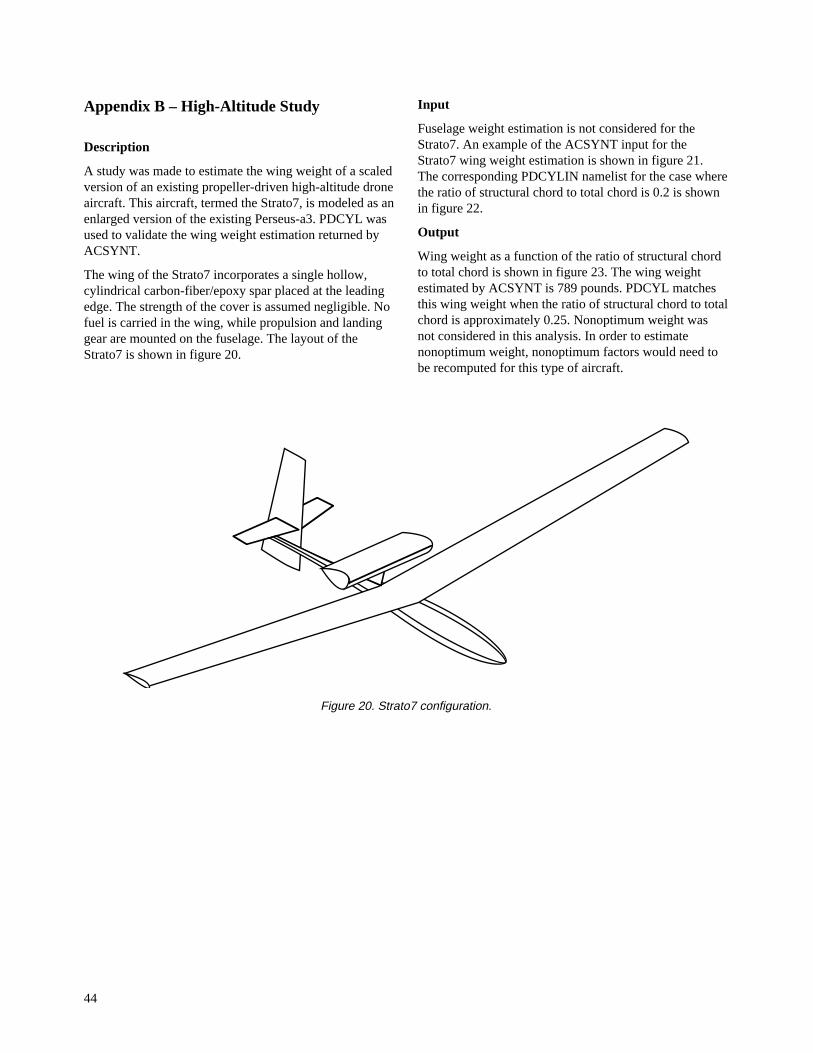
44
Appendix B – High-Altitude Study
Description
A study was made to estimate the wing weight of a scaledversion of an existing propeller-driven high-altitude droneaircraft. This aircraft, termed the Strato7, is modeled as anenlarged version of the existing Perseus-a3. PDCYL wasused to validate the wing weight estimation returned byACSYNT.
The wing of the Strato7 incorporates a single hollow,cylindrical carbon-fiber/epoxy spar placed at the leadingedge. The strength of the cover is assumed negligible. Nofuel is carried in the wing, while propulsion and landinggear are mounted on the fuselage. The layout of theStrato7 is shown in figure 20.
Input
Fuselage weight estimation is not considered for theStrato7. An example of the ACSYNT input for theStrato7 wing weight estimation is shown in figure 21.The corresponding PDCYLIN namelist for the case wherethe ratio of structural chord to total chord is 0.2 is shownin figure 22.
Output
Wing weight as a function of the ratio of structural chordto total chord is shown in figure 23. The wing weightestimated by ACSYNT is 789 pounds. PDCYL matchesthis wing weight when the ratio of structural chord to totalchord is approximately 0.25. Nonoptimum weight wasnot considered in this analysis. In order to estimatenonoptimum weight, nonoptimum factors would need tobe recomputed for this type of aircraft.
Figure 20. Strato7 configuration.

45
TRANSPORT 4 2 2 570 570 0 0 0 2 1 7 0 0.00010 0.6 10000.0 1 2 3 6 1 6 1 6 *** GEOMETRY *** $FUS BDMAX = 3.00, BODL = 24.358, FRAB = 2.01 FRN = 2.15, SFFACT = 1.082664, ITAIL = 1, OUTCOD = 3, $END $WING AR = 23.328, AREA = 500.00, DIHED = 5.0, FDENWG = 0.0, LFLAPC = 0.00, SWEEP = 0.00, SWFACT = 1.0, TAPER = 0.695, TCROOT = 0.14, TCTIP = 0.14, TFLAPC = 0.0, WFFRAC = 0.0, XWING = 0.5664, ZROOT = 1.00, KSWEEP = 2, $END $HTAIL AR = 5.96, AREA = 23.09, SWEEP = 5.00, SWFACT = 1.0, TAPER = 0.682, TCROOT = 0.08, TCTIP = 0.08, XHTAIL = 1.25, ZROOT = 1.25, KSWEEP = 0, SIZIT = T, HTFRAC = -0.20, CVHT = -2.70560, $END $VTAIL AR = 3.08, AREA = 17.69, SWEEP = 5.00, SWFACT = 1.00, TAPER = 0.554, TCROOT = 0.08, TCTIP = 0.08, VTNO = 1.0, XVTAIL = 1.39, YROOT = 0.00, ZROOT = 1.0, KSWEEP = 0, SIZIT = T, VTFRAC = -0.20, CVVT = -0.59909, CGM = 0.40, $END $CREW NCREW = 0, $END $FUEL DEN = 63.78, FRAC = 1.00, $END $FPOD DIAM = 2., LENGTH = 2., X = 0.592 THETA = 90.0, SYMCOD = 1, SOD = -2, $END$ENGINE N = 1, $END$$$$$$$$$$$$$$$$$$$$$$$$$$$$$$$$$$$$$$$$$$$$$$$$$$$$$$$$$$$$$$$$$$$$$$$$$$$$$$$$ $TRDATA CRMACH = .40, QMAX = 70.45, DESLF = 2.5, ULTLF = 3.75, WFUEL = 392.0, WFEXT = 0.0, WFTRAP = 0.1, FRFURE = 0.0, IPSTO1 = 5, TIMTO1 = 0.0, IPSTO2 = 2, TIMTO2 = 1.0, IPSLND = 5, MODLND = 7, VMRGLD = 1.2, WKLAND = 0.1, IBREG = 0, IENDUR = 0, WCOMBP = 0.6, MMPROP = 7, NCODE = 0, NCRUSE = 1, RANGE = 100.0, LENVEL =.FALSE., NLEGCL = 30, NLEGLO = 4, $END 2 MACH NO. ALTITUDE HORIZONTAL NO. VINDPHASE START END START END DIST TIME TURN "G"S WKFUEL M IP IX W B A P------- ---- ---- ----- ----- ------ ----- ---- ----- ------ - -- -- - - - -CLIMB .414 -1 100 -1 0.0 0.0 0.0 -1 1.0000 7 41 0 0 0 0 0LOITER .400 -1 90000 -1 0.0 10.0 0.0 0.0 1.0000 7 21 0 0 0 0 0
***** AERODYNAMICS ***** $ACHAR ABOSB=0.074, ALMAX=20.0, AMC=12.0, ALELJ=3, ISMNDR=0, SFWF=0.99, SMNSWP = 0.01, 0.10, 0.15, 0.20, 0.25, 0.30, 0.35, 0.40, 0.45, 0.51, CLOW = 0.3821,0.3828,0.4266,0.4809,0.4849,0.4888,0.4946,0.5147,0.5502,0.5692, CMO = -.1591,-.1596,-.1531,-.1466,-.1502,-.1538,-.1581,-.1653,-.1749,-.1823, $END $AMULT FCDW=1.1, $END $ATRIM FVCAM = 0.9183,0.9244,0.9538,0.9196,0.9230,0.9276,0.9349,0.9345,0.9264,0.9247, FLDM = 1.0211,1.0254,1.0200,1.0139,1.0200,1.0232,1.0234,1.0205,1.0226,0.8790, FLAPI = 0.0, 0.0, 0.0, 0.0, 0.0, 0.0, 0.0, 0.0, 0.0, 0.0, ITRIM = 1, 1, 1, 1, 1, 1, 1, 1, 1, 1, CGM=0.40, CFLAP=0.0, SPANF=0.0, IVCAM=1, ALFVC=5.0, $END
Figure 21. ACSYNT input for Strato7.

46
$ADET ICOD=1, IPLOT=1, NALF=10, NMDTL=10, ALIN= -6.8, 0.0, 1.0, 2.0, 4.0, 6.0, 8.0, 10.0, 12.0, 14.0, ALTV = 22740.,37475.,50131.,61224.,71097.,79992.,86129.,90000., SMN = 0.085, 0.119, 0.161, 0.210, 0.266, 0.328, 0.379, 0.400, ISTRS= 0, 0, 0, 0, 0, 0, 0, 0, 0, 0, ITB= 0, 0, 0, 0, 0, 0, 0, 0, 0, 0, ITS= 0, 0, 0, 0, 0, 0, 0, 0, 0, 0, $END $ADRAG CDBMB=10*0.0, CDEXTR=10*0.0, CDTNK=10*0.00, $END $ATAKE DELFLD=0.0, DELFTO=0.0, DELLED=0.0, DELLTO=0.0, ALFROT=8.0, $END $APRINT KERROR=2, $ENDSpark Ignition Internal Combustion Engine with Triple Turbocharging $PCONTR HNOUT = 0.,31001.,50131.,79992.,90000., SMNOUT = 0.0, 0.085, 0.161, 0.328, 0.400, NOUTPT = 5, $END $PENGIN ENGNUM = 1, NTPENG = 4, ESZMCH = 0.00, ESZALT = 0., XNMAX = 7200.0, HPENG = 115.0, SWTENG = 6.0, HCRIT = 90000., FSFC = 1.0, $END $PROP AF = 125.0, BL = 2, CLI = 0.5, DPROP = 17.88, FPRW = 0.087437, FTHR = 1.0, NTPPRP = 12, PSZMCH = 0.00, PSZALT = 0., $END $PGEAR GR = 7.43, ETR = .95, FGRW = 0.2476234, GRSND = 14.86, $END $PENGNC XLENG = 1.5, RLENG = 1.0, DIA1 = 1.0, FT = 0.0, FRPN = 1.0, FRBT = 2.0, NBDFT = 0.3, ANACHP = 0., DQ = 0.024, $END TRANSPORT*** WEIGHTS *** $OPTS WGTO = 3000.0, KERROR = 2, SLOPE(1) = 0.47970, TECHI(1) = 0.85, SLOPE(2) = 0.97945, TECHI(2) = 0.85, SLOPE(3) = 0.64225, TECHI(3) = 0.85, SLOPE(4) = 0.85841, TECHI(4) = 0.85, SLOPE(6) = 0.70145, TECHI(6) = 0.85, SLOPE(7) = 0.85396, SLOPE(8) = 0.55290, TECHI(8) = 0.85, SLOPE(9) = 1.89582, TECHI(9) = 0.85, SLOPE(10) = 1.49618, SLOPE(11) = 0.19543, SLOPE(12) = 0.48091, SLOPE(13) = 3.68569, SLOPE(16) = 0.02254, SLOPE(17) = 1.0, KWING = 6, KBODY = 3, $END $FIXW WE = 757.5, WFEQ = 0., WFS = 0., WPL = 0., $END
Figure 21. Concluded.

47
$PDCYLIN
PS=1., TMGW=.05, EFFW=.605,EFFC=1.108, ESW=12.9E06, FCSW=75000., DSW=0.058,
KDEW=1.0, KDFW=1.0,ISTAMA=2, CS1=0.01, CS2=0.75,
CLAQR=.001, IFUEL=1, CWMAN=1.0, CF=6.25E-05,
CKF=5.24, EC=2.00, KGC=.368, KGW=.505,
FTST = 4*58500.,8*0., FTSB = 4*58500.,8*0., FCST = 4*54000.,8*0., FCSB = 4*54000.,8*0., EST = 4*10.70E06,8*0., ESB = 4*10.70E06,8*0., EFT = 4*30.0E06,8*0., EFB = 4*30.0E06,8*0., DST = 4*.101,8*0., DSB = 4*.101,8*0., DFT = 4*.292,8*0., DFB = 4*.292,8*0.,
TMGT = 4*.03,8*0., TMGB = 4*.03,8*0., KDE=0.9, KDF=0.8,
CLBR1=1.1, ICYL = 1,
KCONT = 12*4, KCONB = 12*4,
AXAC=0., CBUM=1.0, CLAN=0.93,CMAN=1.0, ILOAD=3, PGB = 12*11.5, PGT = 12*11.5, WFBUMP=0.001, WFLAND=0.9,
WTFF=0.07,
VSINK=10.0, STROKE=1.0, CLRG1=.395, CLRG2=0.5,WFGR1=0.0031,WFGR2=0.0058, IGEAR=1, GFRL=0.001,CLRGW1=0.20, CLRGW2 = 0.0,
ITAIL=1,
ISCHRENK=1, ICOMND=1, WGNO=1.00, SLFMB=1.2, WMIS=0., WSUR=0., WCW=1.0, WCA=0.0,
NWING=40, $END
Figure 22. PDCYLIN namelist input for Strato7.

48
Box length as a fraction of root chord
PD
CY
L
Win
g
Wei
gh
t,
lb.
0
2 0 0
4 0 0
6 0 0
8 0 0
1 0 0 0
1 2 0 0
1 4 0 0
1 6 0 0
1 8 0 0
0 0.1 0 .2 0 .3 0 .4 0 .5
ACSYNT Weight Scaled from Perseus-a3
Figure 23. Strato7 wing weight as a function of structural box length.

49
References
1. Ardema, M. D.: Body Weight of HypersonicAircraft: Part 1. NASA TM-101028, Oct. 1988.
2. Ardema, M. D.; and Williams, L. J.: TransonicTransport Study − Structures and Aerodynamics,NASA TM X-62,157, May 1972.
3. Ardema, M. D.: Structural Weight Analysis ofHypersonic Aircraft. NASA TN D-6692,Mar. 1972.
4. Ardema, M. D.: Analysis of Bending Loads ofHypersonic Aircraft. NASA TM X-2092, 1970.
5. Moore, M.; and Samuels, J.: ACSYNT AircraftSynthesis Program − User’s Manual. SystemsAnalysis Branch, NASA Ames Research Center,Sept. 1990.
6. Shanley, F. R.: Weight-Strength Analysis of AircraftStructures. Second Edition, Dover, N.Y., 1960.
7. Megson, T. H. G.: Aircraft Structures for Engineer-ing Students. Second Edition, Halsted Press,1990.
8. McCormick, B. W.: Aerodynamics, Aeronautics, andFlight Mechanics. John Wiley & Sons, 1979.
9. Crawford, R. F.; and Burns, A. B.: Strength,Efficiency, and Design Data for BerylliumStructures. ASD-TR-61-692, Feb. 1962.
10. Crawford, R. F.; and Burns, A. B.: Minimum WeightPotentials for Stiffened Plates and Shells.AIAA J., vol. 1, no. 4, Apr. 1963, pp. 879–886.
11. Popov, E. P.: Mechanics of Materials. SecondEdition, Prentice-Hall, N.J., 1976.
12. Marquardt, D. W.: Least Squares Estimation ofNonlinear Parameters, a Computer Program inFORTRAN IV Language. IBM SHARE Library,Distribution Number 309401, Aug. 1966.
13. Niu, M. C.-Y.: Airframe Structural Design: PracticalDesign Information and Data on AircraftStructures. Conmilit Press, 1991.
14. York, P.; and Labell, R. W.: Aircraft Wing WeightBuild-Up Methodology with Modification forMaterials and Construction Techniques. NASACR-166173, Sept. 1980.
15. Thomas, R. B.; and Parsons, S. P.: Weight DataBase. The Boeing Company, CommercialAirplane Division, Weight Research Group,Doc. No. D6-23204 TN, 1968.
16. McDonnell Douglas Aircraft Company, DetailedWeight Statement for MD-11 Transport Aircraft,June 1987.
17. McDonnell Douglas Aircraft Company, DetailedWeight Statement for MD-80 Transport Aircraft,July 1991.

REPORT DOCUMENTATION PAGE
8. PERFORMING ORGANIZATION REPORT NUMBER
10. SPONSORING/MONITORING AGENCY REPORT NUMBER
Form Approved
OMB No. 0704-0188
12b. DISTRIBUTION CODE12a. DISTRIBUTION/AVAILABILITY STATEMENT
7. PERFORMING ORGANIZATION NAME(S) AND ADDRESS(ES)
4. TITLE AND SUBTITLE 5. FUNDING NUMBERS
6. AUTHOR(S)
1. AGENCY USE ONLY (Leave blank)
9. SPONSORING/MONITORING AGENCY NAME(S) AND ADDRESS(ES)
2. REPORT DATE 3. REPORT TYPE AND DATES COVERED
15. NUMBER OF PAGES
16. PRICE CODE
20. LIMITATION OF ABSTRACT19. SECURITY CLASSIFICATION OF ABSTRACT
18. SECURITY CLASSIFICATION OF THIS PAGE
17. SECURITY CLASSIFICATION OF REPORT
14. SUBJECT TERMS
13. ABSTRACT (Maximum 200 words)
Standard Form 298 (Rev. 2-89)Prescribed by ANSI Std. Z39-18298-102
NSN 7540-01-280-5500
Public reporting burden for this collection of information is estimated to average 1 hour per response, including the time for reviewing instructions, searching existing data sources,gathering and maintaining the data needed, and completing and reviewing the collection of information. Send comments regarding this burden estimate or any other aspect of thiscollection of information, including suggestions for reducing this burden, to Washington Headquarters Services, Directorate for information Operations and Reports, 1215 JeffersonDavis Highway, Suite 1204, Arlington, VA 22202-4302, and to the Office of Management and Budget, Paperwork Reduction Project (0704-0188), Washington, DC 20503.
11. SUPPLEMENTARY NOTES
Unclassified Unclassified
Unclassified — UnlimitedSubject Category 05
A-961451
NASA TM-110392
May 1996
Ames Research CenterMoffett Field, CA 94035-1000
National Aeronautics and Space AdministrationWashington, DC 20546-0001
538-08-11
55
A04
Analytical Fuselage and Wing Weight Estimation of Transport Aircraft
Mark D. Ardema,* Mark C. Chambers,* Anthony P. Patron,*Andrew S. Hahn, Hirokazu Miura, and Mark D. Moore
A method of estimating the load-bearing fuselage weight and wing weight of transport aircraft based onfundamental structural principles has been developed. This method of weight estimation represents acompromise between the rapid assessment of component weight using empirical methods based on actualweights of existing aircraft, and detailed, but time-consuming, analysis using the finite element method. Themethod was applied to eight existing subsonic transports for validation and correlation. Integration of theresulting computer program, PDCYL, has been made into the weights-calculating module of the AirCraftSYNThesis (ACSYNT) computer program. ACSYNT has traditionally used only empirical weight estima-tion methods; PDCYL adds to ACSYNT a rapid, accurate means of assessing the fuselage and wing weightsof unconventional aircraft. PDCYL also allows flexibility in the choice of structural concept, as well as adirect means of determining the impact of advanced materials on structural weight.
Using statistical analysis techniques, relations between the load-bearing fuselage and wing weightscalculated by PDCYL and corresponding actual weights were determined. A User's Manual and two sampleoutputs, one for a typical transport and another for an advanced concept vehicle, are given in the appendices.
Structural analysis, Weight estimation, Transport aircraft
Technical Memorandum
Point of Contact: Mark Ardema, Ames Research Center, MS 237-11, Moffett Field, CA 94035-1000 (415) 604-6651
*Santa Clara University, Santa Clara, California