analysis to strategies - international atomic energy … · analysis to strategies ... ref: epri...
TRANSCRIPT

IAEA Workshop on the Development of Severe Accident Management Guidelines11-15 December 2017, Vienna, Austria
presented by
Yasunori YAMANAKA (NRRC of CRIEPI)
Analysis to Strategies:Accident Prevention and Mitigation Strategies

Strategies
• Initial Tasks (Accident Management)
– Prevent further escalation
– Mitigate consequences
– Achieve safe stable state
• Severe Accident Management
– Terminate progress of accident
– Protect FP boundaries
– Minimize releases
2

FP Boundary Threats - overview
2.1 Large release at onset of accident
2.2 Bypass of the containment (SGTR, SGT creep R, ISLOCA)
2.3 High Pressure Melt Ejection (HPME)
2.4 Core cooling, ultimate heat sink and RPV melt-through
2.5 Hydrogen production and combustion
2.6 Molten Core Concrete Interaction (MCCI)
2.7 Containment pressurisation
2.8 Containment sub-atmospheric pressure
2.9 Spent Fuel Pool damages (next lecture)
2.10 Release of Fission Products to the environment
2.11 Exit of SAMG, long term provisions
3
Recall Fission Product Boundary Challenges:

Potential for Large Releases
• Initiating event (examples)
– Reactivity event
– Large external event
– Aircraft impact
• Accident progression
– Steam explosions
– Hydrogen deflagration/detonation
– Direct Containment Heating
4
Large releases require immediate attention to protect staff and public

Large Releases Strategies
• Habitability challenges
• Desire to locate the breach and isolate
– Use of internal and external sprays
– External filters
– Operation of ventilation systems
• Requires close integration with Emergency Preparedness (EP) plan
5

Containment Bypass
• Possible confusion with containment impairment or pre-existing failure of containment
– Impairment and pre-existing failure• Opening in containment occurs prior to core damage
• Bypass – normally refers to the creation of a direct release path from the RCS/RPV to the environment
– Induced SGTR (post-core damage)
– Interfacing system LOCA (pre-core damage)
6

High Pressure Melt Ejection
• Requires elevated RCS/RPV pressure (e.g. > 2 Mpa)
• Spread of molten debris over large containment volume
• Debris stored heat transferred to containment atmosphere
• Short time scale
7
Ref: NUREG/CR-6533, Code Manual for CONTAIN 2.0, 1997

Direct Containment Heating
• As a result of HPME, rapid heat-up of the containment atmosphere could occur with a consequential pressure spike
• DCH important factors:
– Cavity geometry
– De-entrainment of debris
– Re-entrainment of debris
• HPME can also impact the final debris distribution and success of debris cooling
8

Debris Transport
9
Ref: EPRI Technical Basis Report, 2012

Strategies for HPME/DCH
• Depressurize the RCS/RPV
– Restore secondary side cooling (PWR)
– Operate isolation condenser (BWR)
– Depressurize the steam generator(s) (PWR)
– Open primary safety valves (BWR & PWR)
– Open main steam drain lines (BWR)
10
RCS depressurization also allows injection from low pressure sources

Core cooling, ultimate heat sink andRPV melt-through
• Challenges
– Heat-up, melting and relocation of core material
– Potential for melt/oxide stratification in lower plenum and “focusing effect”
– Attack of lower plenum penetrations
11
Primary strategy is to prevent or delay vessel failure
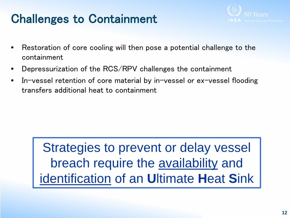
Challenges to Containment
• Restoration of core cooling will then pose a potential challenge to the containment
• Depressurization of the RCS/RPV challenges the containment
• In-vessel retention of core material by in-vessel or ex-vessel flooding transfers additional heat to containment
12
Strategies to prevent or delay vessel breach require the availability and
identification of an Ultimate Heat Sink

Hydrogen Generation
13
• Steam oxidation of zirconium fuel cladding
• CO also generated ex-vessel due to core-concrete interactions
• Hydrogen flammable
– Ignition at 4%
– Flame acceleration at 8%
– Deflagration-to-Detonation Transition at 14%
• Steam inerting at 55%
Ref. www.world-nucler.org

Hydrogen Strategies
1. No strategy – pressure rise well within containment capability
2. Mixing containment atmosphere to prevent locally high concentrations– May be a consequence of containment design
– Active systems to promote mixing
3. Inerting containment atmosphere– Employed in BWR Mark I and II design
– Dilution from purging systems
14

Hydrogen Strategies (cont’d)
4. Purging containment by vent and purge
5. Intentional consumption of hydrogen
– Passive autocatalytic recombiners
– Hydrogen igniters
– Combination of two above
15

Implementing H2 Strategies
• Hydrogen monitoring system
• Sampling
• Computational aids
– Core Damage Assessment Guide
– H2 flammability curve
16
Ref. NUREG/CR-3468
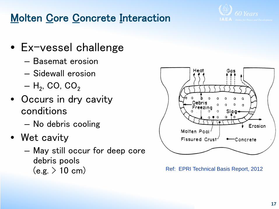
Molten Core Concrete Interaction
• Ex-vessel challenge– Basemat erosion
– Sidewall erosion
– H2, CO, CO2
• Occurs in dry cavity conditions– No debris cooling
• Wet cavity– May still occur for deep core
debris pools (e.g. > 10 cm)
17
Ref: EPRI Technical Basis Report, 2012
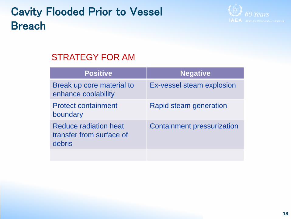
Cavity Flooded Prior to Vessel Breach
18
Positive NegativeBreak up core material to enhance coolability
Ex-vessel steam explosion
Protect containment boundary
Rapid steam generation
Reduce radiation heat transfer from surface of debris
Containment pressurization
STRATEGY FOR AM

GE HITACHI Ex-vessel Core Cooling
19
Ref: Risk-Informing ESBWR Design with Probabilistic Safety Assessments, INPRO Dialogue Forum, Nov. 2013

AREVA Ex-vessel Core Cooling
20
Ref: INPRO User Requirement 1.4 ‘Release into the Containment’ Position of the EPR reactor, INPRO dialogue forum, Nov. 2013
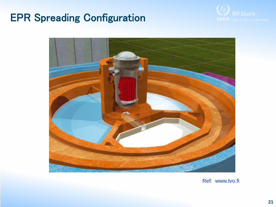
EPR Spreading Configuration
21
Ref: www.tvo.fi
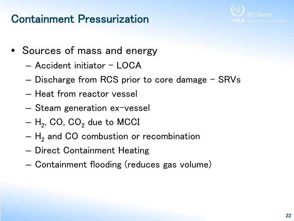
Containment Pressurization
• Sources of mass and energy
– Accident initiator – LOCA
– Discharge from RCS prior to core damage – SRVs
– Heat from reactor vessel
– Steam generation ex-vessel
– H2, CO, CO2 due to MCCI
– H2 and CO combustion or recombination
– Direct Containment Heating
– Containment flooding (reduces gas volume)
22

Containment Capability
• Typical PSA includes structural analysis of the containment
– Considers several potential failure locations
– Includes both pressure and temperature challenges
– Looks at static and dynamic loads
– Addresses penetrations and seals in addition to structural components
23
Containment capability assessment is critical to planning AM strategies

Strategies for Containment Pressure Control
• Vent
– Could use ventilation system
– may be limited capacity
• Containment coolers
• Sprays
24
Filtered Venting system installed at KKL (Switzerland)

Cautions to be addressed in AM
• H2 in ventilation system
• Aerosols can clog ventilation system filters
• Sprays can de-inert containment atmosphere
• High radiation in proximity of vent path
25

Sub-atmospheric Pressure -Challenge
• Leakage or venting of non-condensable gas may later lead to sub-atmospheric conditions if steam is removed
• Containment structures not designed for significant negative pressure force
26

Sub-atmospheric Pressure -Strategies
• Containment vacuum breakers
– Confirm operation during a severe accident
• Termination of sprays and coolers at low pressure
• Purge containment atmosphere
27

Release Consequences
• Habitability constraints– Containment leakage
– Bypass
– Failure
– Venting
– Steam generator tube rupture
– Isolation condenser tube failure
– Drywell liner failure
– Basemat failure
– Spent fuel pool release
28

Release Mitigation Strategies
• Discussed in previous sections
– Venting, sprays, etc.
• Preparations need to be taken for site access, lodging, food, water, fuel, medical, communications
29

Contaminated Water Management
• pH control of water pools
• Continued makeup to prevent pool dryout and revaporization of fission products
• Capture and storage of contaminated run-off water
30

Long Term Provisions
• SAMGs are typically developed for short (days) term response
– Place plant into a safe stable state
• Can be supplemented with longer term (weeks, months, years) provisions
– Repair of failed systems
– Staff change
31
Exit conditions can be identified and tracked using logic diagram or similar techniques

Examples of Safe, Stable Conditions
• Site release terminated or small and decreasing
• Core debris covered and cooled
• RCS pressure low and stable
• Containment pressure low and stable
– Combustible gasses under control
• Water management under control
32

Spent Fuel Pool Challenges
• Damage due to:
– Initiating event (e.g. seismic event)• Pool drain can create rapidly developing challenge
– Loss of pool cooling• Slower evolving challenge due to heat-up and boil-off
• Typically Spent Fuel Pool not inside containment, therefore, potential for unscrubbed release
33

Spent Fuel Pool Strategies
• Water makeup
– Fire water, hoses, portable pumps
• Spraying (mitigate pool drain event
• Ventilation
– Opening of panels and doors
– Active fans
34

Example of SAM Measures by TEPCO - Overview
35
PARMitigation FP Release
Alternative PCV Spray
Filtered Venting System
Water injection into lower drywell
Top head flange cooling
R/B Top VentHydrogen Detectors
Hydrogen Control
Prevent PCV Failure
All rights reserved by TEPCO HD
Filtered Venting System
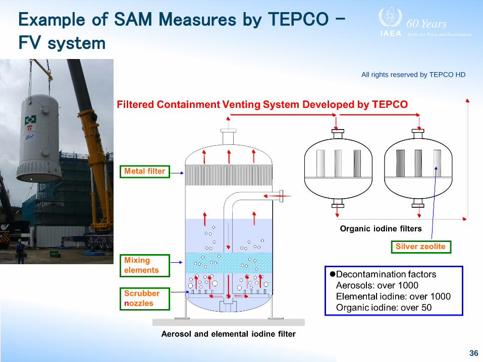
Example of SAM Measures by TEPCO –FV system
36
All rights reserved by TEPCO HD

37All rights reserved by TEPCO HD
Example of SAM Measures by TEPCO – ARCS
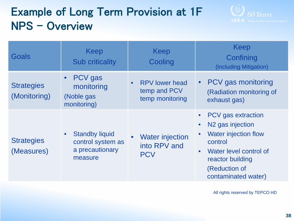
Example of Long Term Provision at 1F NPS - Overview
GoalsKeep
Sub criticalityKeep
Cooling
Keep Confining
(Including Mitigation)
Strategies(Monitoring)
• PCV gas monitoring
(Noble gas monitoring)
• RPV lower head temp and PCV temp monitoring
• PCV gas monitoring(Radiation monitoring of exhaust gas)
Strategies(Measures)
• Standby liquid control system as a precautionary measure
• Water injection into RPV and PCV
• PCV gas extraction• N2 gas injection• Water injection flow
control• Water level control of
reactor building(Reduction of contaminated water)
38
All rights reserved by TEPCO HD

Example of Long Term Provision at 1F NPS –Hydrogen Management
• H2 is produced with water radiolysis– The locations of hydrogen generation (= debris location) is unknown
• Control H2 concentration under the flammability limit by N2 injection– To prevent locally high concentrations, N2 injection points should be
carefully considered.
• Measure H2 concentration in the PCV gas control system
39
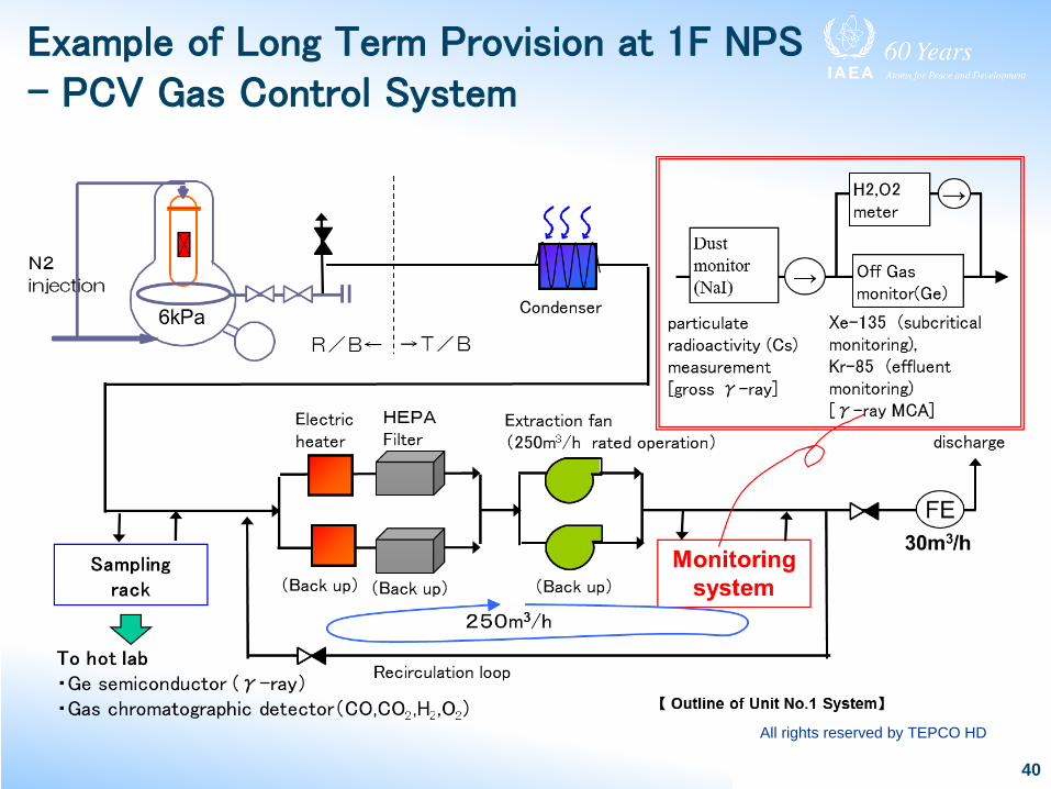
Example of Long Term Provision at 1F NPS – PCV Gas Control System
40
All rights reserved by TEPCO HD
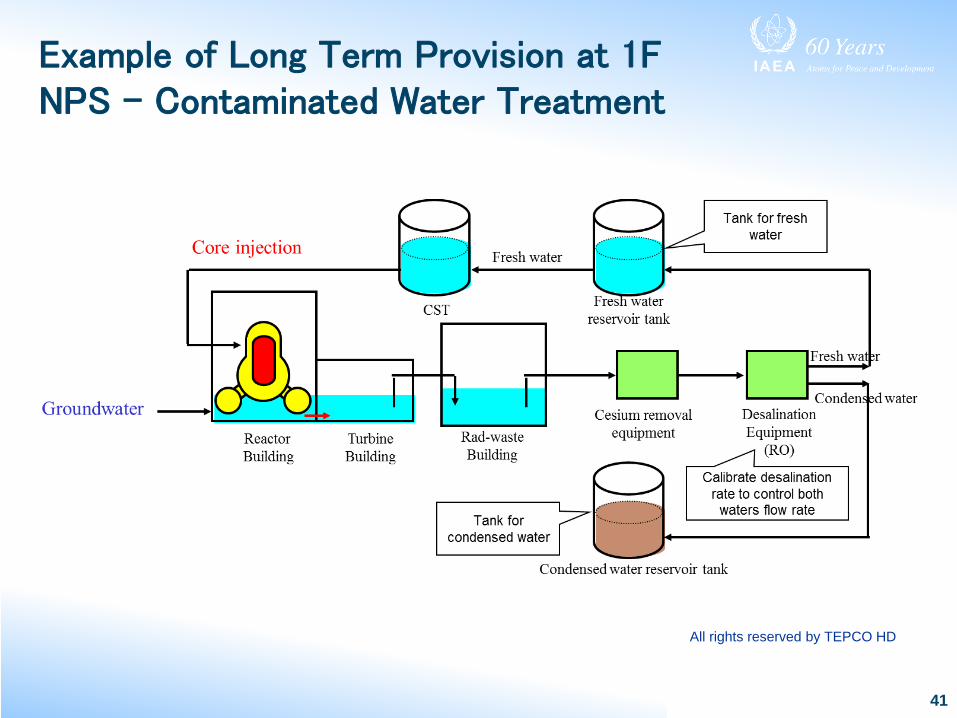
Example of Long Term Provision at 1F NPS – Contaminated Water Treatment
41
All rights reserved by TEPCO HD

Plant Damage Conditions (PDC)
• EPRI TBR
– Characterization of severe accident progression
– Extent of fuel damage
– Containment status
• PDC helps identify available fission product barrier to be protected
• Barriers include fuel, RCS, spent fuel, primary, and secondary containment
42

Candidate High Level Actions
43
Limit Potential for Releases
Recover core
Maintain containment
integrity
Minimize releases
from containment
Minimize off-site
releases

Overview of Candidate High Level Actions
44
No. Candidate High Level Action1. Inject into (makeup to) reactor pressure
vessel/reactor coolant system (RPV/RCS)2. Depressurize the RPV/RCS3. Spray within the RPV (BWR)4. Restart reactor coolant pump (RCP) (PWR)5. Depressurize steam generators (PWR)6. Inject into (feed) the steam generators (PWR)7. Operate isolation condenser (IC) (BWR)8. Spray into containment9. Inject into containment10. Operate fan coolers11. Operate recombiners12. Operate igniters

Overview of Candidate High Level Actions
45
No. Candidate High Level Action13. Inert the containment with noncondensable gases
(BWR)14. Vent the primary containment15. Spray the secondary containment16. Flood the secondary containment17. Inject into the spent fuel pool18. Spray the spent fuel pool19. Vent/ventilate the reactor building or auxiliary
building20. Scrub releases by external spraying of buildings

Severe Accident Phenomenology
Fission Product Barrier/Issue Phenomenological Challenge
Fuel reactivity RecriticalityFuel cladding Ballooning and rupture
Over temperature and oxidationRCS Hot leg creep rupture (PWR)
Steam generator tube rupture (PWR)Overpressure
RPV Main steam line creep failure (BWR)Stuck-open SRV (BWR)OverpressureIn-vessel steam explosionMolten jet attackCreep failure of the lower headPenetration failure
46
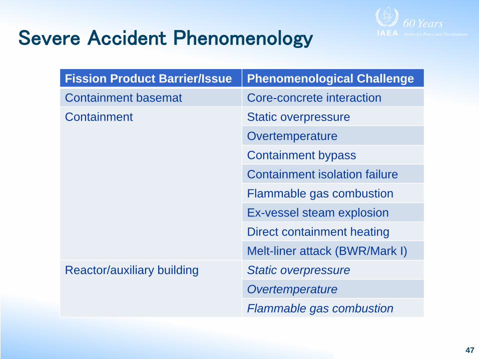
Severe Accident Phenomenology
47
Fission Product Barrier/Issue Phenomenological ChallengeContainment basemat Core-concrete interactionContainment Static overpressure
OvertemperatureContainment bypassContainment isolation failureFlammable gas combustionEx-vessel steam explosionDirect containment heatingMelt-liner attack (BWR/Mark I)
Reactor/auxiliary building Static overpressureOvertemperatureFlammable gas combustion

Candidate High Level ActionsRecover Fuel
• Injection needed defined by decay heat– Must remove at least all decay heat to begin recovery
• Time to recover influenced by– Exothermic energy addition from metal oxidation
– Stored energy in core materials
• Two injection thresholds– Decay heat converted into latent energy (vaporization)
– Decay heat converted into sensible energy
48
Wvap
Wsat

Stages of Core Damage
49
OX• Degraded fuel conditions• Cladding oxidation significant• Fuel degradation sufficient to lead to appreciable fuel debris relocation• Potential for critical fuel configurations
BD• Degraded fuel conditions with RCS/RPV challenged• Significant fuel relocation• Coolability of the fuel geometry degraded
EX• Degraded fuel conditions with RCS/RPV lower head breached• Core debris relocation into containment occurred• Direct attack of the concrete containment can occur
Ref: EPRI Technical Basis Report, 2012

Candidate High Level ActionsRecover Core
Recover Core
OX
Operate Isolation
Condenser
OX/BD
Inject into RPV/RCS
Spray within the RPV (BWR)
Restart the RCPs (PWR)
Inject into (Feed) the
SGs
EX
Spray into containment
Inject into or flood
containment
Operate the containment fan coolers
OX/BD/EX(BWR)
Inject into SFP
Spray into SFP
50

Stages of Containment Damage
51
CC• Containment intact and cooled
CH• Containment challenged• Appreciable buildup of energy• Presence of flammable gases in containment
B• Containment bypass• Direct pathway from RCS/RPV out of containment (e.g. SGTR,
ISLOCA)
I• Containment impaired• Containment isolation failure or some other breach• Direct pathway out of containment exists
Ref: EPRI Technical Basis Report, 2012
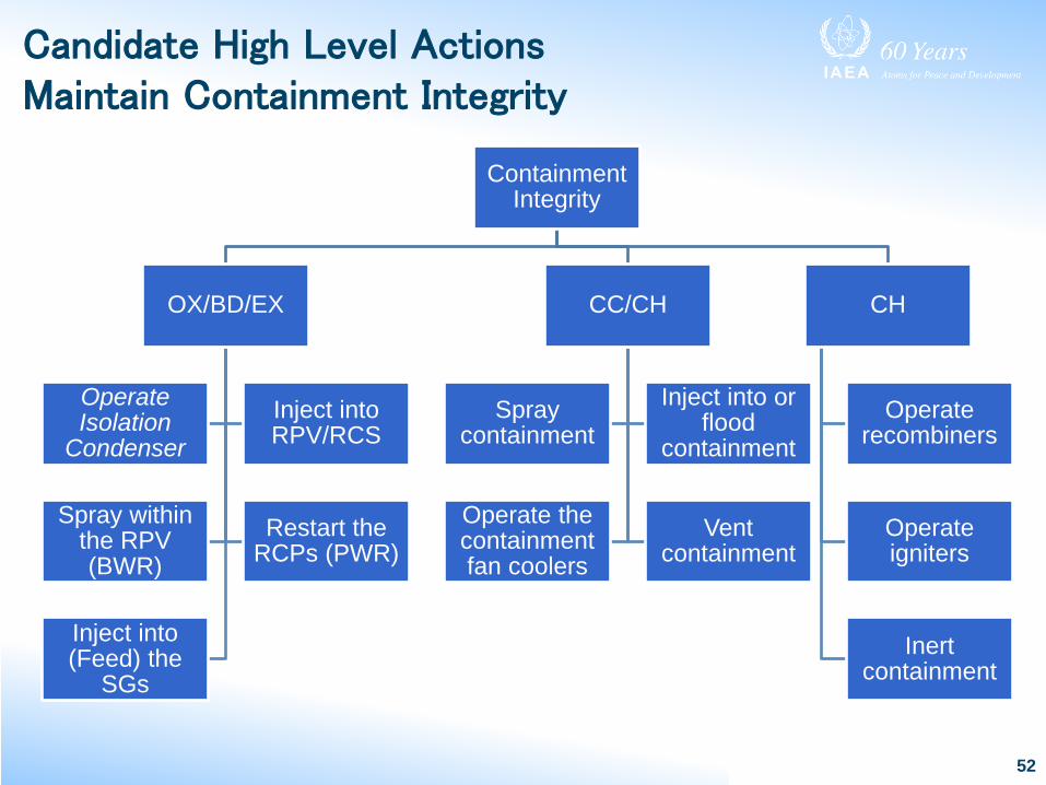
Candidate High Level ActionsMaintain Containment Integrity
Containment Integrity
OX/BD/EX
Operate Isolation
CondenserInject into RPV/RCS
Spray within the RPV (BWR)
Restart the RCPs (PWR)
Inject into (Feed) the
SGs
CC/CH
Spray containment
Inject into or flood
containment
Operate the containment fan coolers
Vent containment
CH
Operate recombiners
Operate igniters
Inert containment
52

Candidate High Level ActionsMinimize Radiological Release from Containment
53
Minimize release from containment
OX/BD/EX
Inject into RPV/RCS
Spray within RPV (BWR)
B(ypass)
Inject into (feed) SGs (PWR)
Operate Isolation Condenser (BWR)
Spray reactor/auxiliary
building
Flood reactor/auxiliary
building
Vent/ventilate reactor/auxiliary
building
I(mpaired)
Spray containment
Inject into or flood containment
Operate fan coolers Vent containment

Stages of Spent Fuel Pool Damage
54
SFP-OX
• Degraded conditions• Cladding oxidation significant• Fuel degradation sufficient to lead to appreciable fuel
debris relocation• Potential for critical fuel configurations
SFP-BD
• Degraded conditions with challenge to SFP structure• Significant material relocation• Coolability of the fuel assembly geometry degraded
Ref: EPRI Technical Basis Report, 2012

Candidate High Level ActionsRecover Spent Fuel
55
Recover Spent Fuel
OX/BD
Inject into RPV/RCS
Spray into RPV/RCS
(BWR)
SFP-OX/SFP-BD
Spray into SFP
Inject into SFP

Reactor/Auxiliary Building Damage Conditions
56
SC-CC• Reactor/auxiliary building intact and cooled
SC-CH
• Reactor/auxiliary building challenged• Appreciable buildup of energy• Presence of flammable gases in building atmosphere
SC-I• Reactor/auxiliary building impaired• Direct pathway to environment exists

Candidate High Level ActionsMinimize Off-site Radiological Release
57
Minimize off-site release
OX/BD/EXSFP-OX/SFP-
BD
Inject into RPV/RCS
Spray within RPV (BWR)
Inject into SFP Spray into SFP
SC-CH
Vent/ventilate reactor/auxiliary
building
SC-I
Spray into reactor/auxiliary
building
External spray of building to
scrub releases