analysis of weight reduction in connecting rod … · avishek, m. and arpan, m. (2016). orbital...
TRANSCRIPT
ANALYSIS OF WEIGHT REDUCTION IN CONNECTING ROD BY USING DIFFERENT MATERIALS IN ANSYS
PRAKASH S1*, PRABHAHAR M2, JESHURAN SAMUEL J3 AND MANISH KUMAR S3
1Research Scholar, Aarupadai Veedu Institute of Technology, Vinayaka Mission University, India.
2Professor, Department of Mechanical Engineering, Aarupadai Veedu Institute of Technology, India.
(Received 25 May, 2017; accepted 22 December, 2017)
Key words: Connecting rod, Autodesk inventor, FEA, ANSYS workbench
Jr. of Industrial Pollution Control 33(2)(2017) pp 1739-1744www.icontrolpollution.comResearch Article
*Corresponding authors email: [email protected]
INTRODUCTION
Sheet Metal Formability
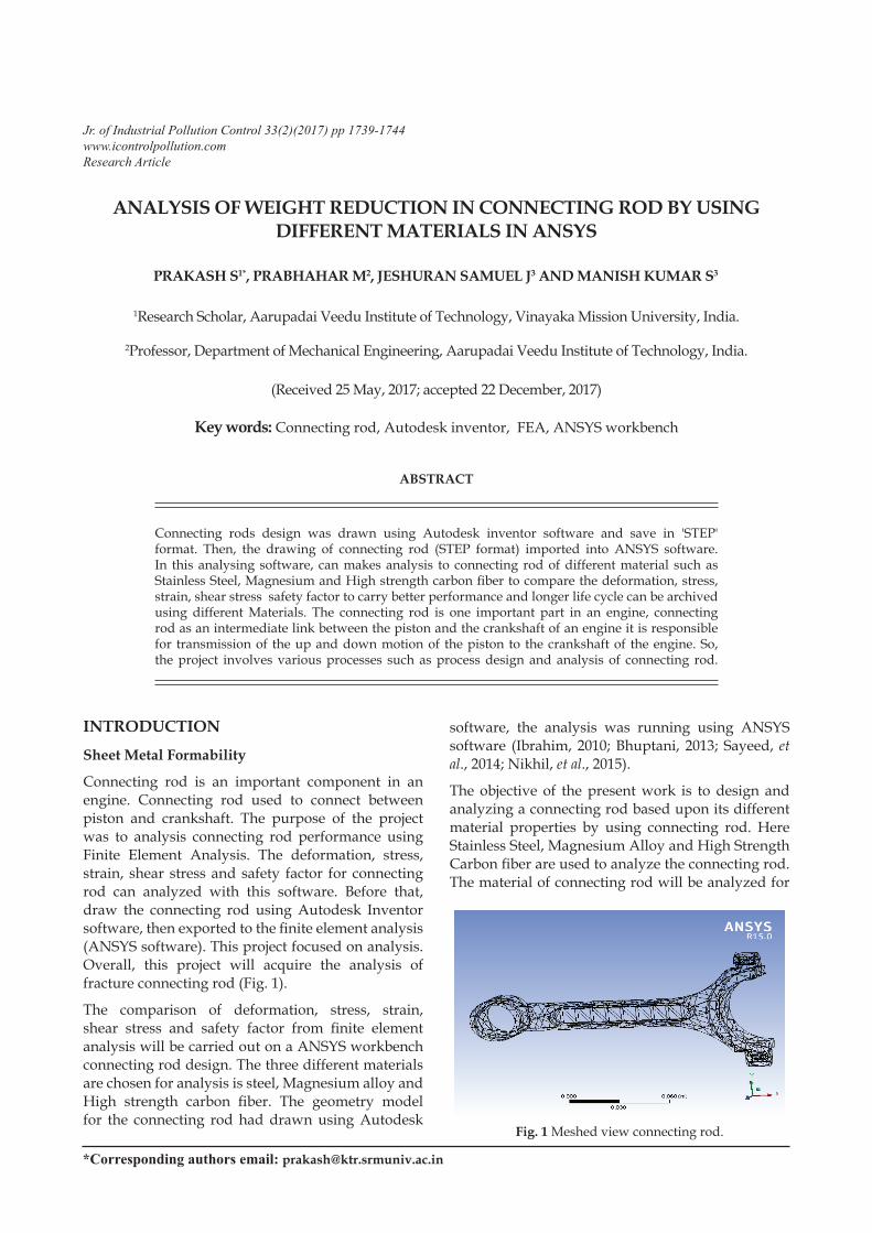
Connecting rod is an important component in an engine. Connecting rod used to connect between piston and crankshaft. The purpose of the project was to analysis connecting rod performance using Finite Element Analysis. The deformation, stress, strain, shear stress and safety factor for connecting rod can analyzed with this software. Before that, draw the connecting rod using Autodesk Inventor software, then exported to the finite element analysis (ANSYS software). This project focused on analysis. Overall, this project will acquire the analysis of fracture connecting rod (Fig. 1).
The comparison of deformation, stress, strain, shear stress and safety factor from finite element analysis will be carried out on a ANSYS workbench connecting rod design. The three different materials are chosen for analysis is steel, Magnesium alloy and High strength carbon fiber. The geometry model for the connecting rod had drawn using Autodesk
software, the analysis was running using ANSYS software (Ibrahim, 2010; Bhuptani, 2013; Sayeed, et al., 2014; Nikhil, et al., 2015).
The objective of the present work is to design and analyzing a connecting rod based upon its different material properties by using connecting rod. Here Stainless Steel, Magnesium Alloy and High Strength Carbon fiber are used to analyze the connecting rod. The material of connecting rod will be analyzed for
ABSTRACT
Connecting rods design was drawn using Autodesk inventor software and save in 'STEP' format. Then, the drawing of connecting rod (STEP format) imported into ANSYS software. In this analysing software, can makes analysis to connecting rod of different material such as Stainless Steel, Magnesium and High strength carbon fiber to compare the deformation, stress, strain, shear stress safety factor to carry better performance and longer life cycle can be archived using different Materials. The connecting rod is one important part in an engine, connecting rod as an intermediate link between the piston and the crankshaft of an engine it is responsible for transmission of the up and down motion of the piston to the crankshaft of the engine. So, the project involves various processes such as process design and analysis of connecting rod.
Fig. 1 Meshed view connecting rod.
1740 PRAKASH ET AL.
better result output. CAD model of connecting rod will be modelled in Autodesk inventor and then be analyzed in ANSYS Software. After analysis a comparison will be made between existing material and alternate material which will be suggested for the connecting rod in terms of deformation, stresses and strain and the desired output results can be achieved.
DISCUSSIONMaterials For Connecting Rod
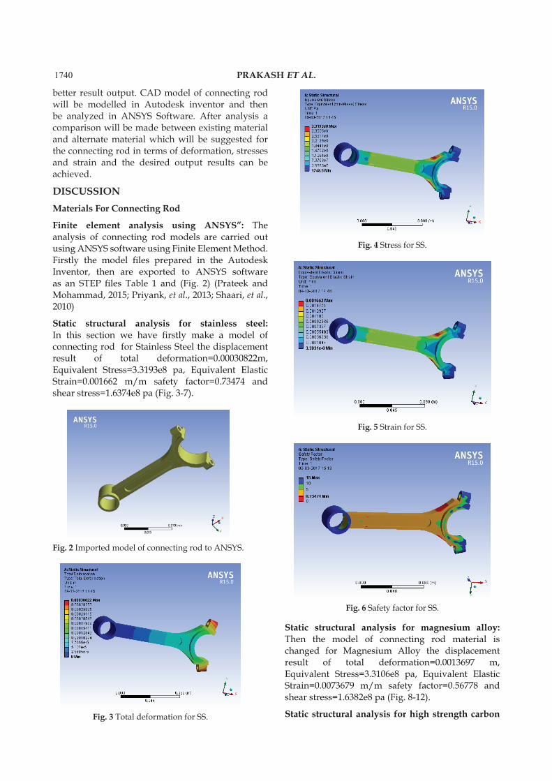
Finite element analysis using ANSYS”: The analysis of connecting rod models are carried out using ANSYS software using Finite Element Method. Firstly the model files prepared in the Autodesk Inventor, then are exported to ANSYS software as an STEP files Table 1 and (Fig. 2) (Prateek and Mohammad, 2015; Priyank, et al., 2013; Shaari, et al., 2010)
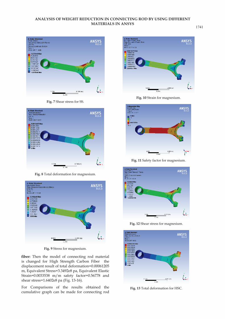
Static structural analysis for stainless steel: In this section we have firstly make a model of connecting rod for Stainless Steel the displacement result of total deformation=0.00030822m, Equivalent Stress=3.3193e8 pa, Equivalent Elastic Strain=0.001662 m/m safety factor=0.73474 and shear stress=1.6374e8 pa (Fig. 3-7).
Static structural analysis for magnesium alloy: Then the model of connecting rod material is changed for Magnesium Alloy the displacement result of total deformation=0.0013697 m, Equivalent Stress=3.3106e8 pa, Equivalent Elastic Strain=0.0073679 m/m safety factor=0.56778 and shear stress=1.6382e8 pa (Fig. 8-12).
Static structural analysis for high strength carbon
Fig. 2 Imported model of connecting rod to ANSYS.
Fig. 3 Total deformation for SS.
Fig. 4 Stress for SS.
Fig. 5 Strain for SS.
Fig. 6 Safety factor for SS.
1741
ANALYSIS OF WEIGHT REDUCTION IN CONNECTING ROD BY USING DIFFERENT MATERIALS IN ANSYS
fiber: Then the model of connecting rod material is changed for High Strength Carbon Fiber the displacement result of total deformation=0.00061205 m, Equivalent Stress=3.3492e8 pa, Equivalent Elastic Strain=0.0033538 m/m safety factor=0.56778 and shear stress=1.6402e8 pa (Fig. 13-16).
For Comparisons of the results obtained the cumulative graph can be made for connecting rod
Fig. 7 Shear stress for SS.
Fig. 8 Total deformation for magnesium.
Fig. 9 Stress for magnesium.
Fig. 10 Strain for magnesium.
Fig. 11 Safety factor for magnesium.
Fig. 12 Shear stress for magnesium.
Fig. 13 Total deformation for HSC.

1742 PRAKASH ET AL.
for displacement (Deformation), von-misses stress, strain, safety factor and shear stress (Fig. 17-21).
CONCLUSIONThe forces were applied on the piston head and crank shaft connecting head the effect of it on the connecting rod was studied in this analysis. The
Fig. 14 Stress for HSC.
Fig. 15 Strain for HSC.
Fig. 16 Shear stress for HSC.
Fig. 17 Deformation.
Fig. 18 Equivalent stress.
Fig. 19 Equivalent elastic strain.
Fig. 20 Safety factor.
Fig. 21 Shear stress.
1743
ANALYSIS OF WEIGHT REDUCTION IN CONNECTING ROD BY USING DIFFERENT MATERIALS IN ANSYS
pressure developed for connecting rod is analyzed for displacement (deformation), vonmisses stress, strain, safety factor and shear stress intensity output. The results or conclusion thus that can make on the bases of the output results by ANSYS can be as followed, It is observed that displacement(deformation), vonmisses stress, strain, safety factor and shear stress induced in the Connecting Rod made up of high strength Carbon fiber is comparatively closer to stainless steel, thus more advancement in the field of high strength carbon Fiber is required to be as equivalent and efficiently used as Stainless Steel, Connecting rod for Stainless Steel the displacement result of total deformation=0.00030822m, Equivalent Stressg=3.3193e8 pa, Equivalent Elastic Strain=0.001662 m/m safety factor=0.73474 and shear stress=1.6374e8 pa, Connecting rod for High Strength Carbon Fiber the displacement result of total deformation=0.00061205 m, Equivalent Stress=3.3492e8 pa, Equivalent Elastic Strain=0.0033538 m/m safety factor=0.56778 and shear stress=1.6402e8 pa.
REFERENCESAmeziane-Hassani, H. and Neale, K.W. (1991). On
the analysis of sheet metal wrinkling. International journal of mechanical sciences. 33 : 13-30.
Banabic, D., Bunge, H.J., Pöhlandt, K. and Tekkaya, A.E. (2000). Formability of metallic materials. Engineering Materials.
Beddoes, J. and Bibby, M. (1992). Principles of metal manufacturing processes. Butterworth-Heinemann. Arnold. London.
Callister, W.D. (1997). Materials science and engineering: An introduction. 4th edn. John Wiley & Sons Inc, NY, USA.
Gensamer, M. (1946). Strength and ductility. Trans. ASM. 36 : 30-60.
Goodwin, G.M. (1968). Application of strain analysis to sheet metal forming problem in the press shop. Society of Automotive Engineers. 380-387.
Havránek, T. (1975). Statistical quantifiers in observational calculi: An application in GUHA-methods. Theory and Decision. 6 : 213-230.
Hosford, W.F. and Ducan, J.L. (1999). Sheet metal forming: A review. JOM. 51 : 39-44.
Hosford. and Caddell. (2007). Metal forming mechanics and metallurgy. 3rd edition. Cambridge University Press.
Keeler, S.P. and Backofen, W.A. (1963). Plastic instability and fracture in sheets stretched over rigid punches. Asm Trans Q. 56 : 25-48.
Lankford, W.I., Snyder, S.C. and Bauscher, J.A. (1950). New criteria for predicting the press performance of deep-drawing sheets. Trans. ASM. 42.
Lee. (1987). Wrinklinn in sheet metal forming Interdisciplinary issues in materials processing and manufacturing: presented at the Winter Annual Meeting of the AMER. ASME, New York, NY, USA. 2 : 419-436.
Logan, R.W. and Hosford, W.F. (1985). Wall wrinkling during stretch draw: Simulation and experiment. Computer modeling of sheet metal forming process: Theory, verification and application. pp: 225-242.
Marciniak, Z., Duncan, J.L. and Hu, S.J. (2002). Mechanics of sheet metal forming. 2nd edn. Butterworth-Heinemann. Oxford, UK.
Mellor, P.B. (1956). Stretch forming under fluid pressure. Journal of the Mechanics and Physics of Solids. 5 : 41-56.
Naziri, H. and Pearce, R. (1968). The effect of plastic anisotropy on flange-wrinkling behaviour during sheet metal forming. International Journal of Mechanical Sciences. 10 : 681-694.
Ni, C.M. and Jhita, R. (1990). A numerical technique for predicting wrinkling in practical sheet metal forming processes. Computer Modeling and simulation and modeling of manufacturing processes. ASME Materials Division. 20 : 139-153.
Saran, M.J., Schedin, E., Samuelsson, A., Melander, A. and Gustafsson, C. (1990). Numencal and experirnental investigations of deep drawing of metal sheets. ASME. J. Eng. Ind. 112 : 272-277
Sivam, S.P.S.S., Gopal, M., Venkatasamy, S. and Siddhartha, S. (2015). An experimental investigation and optimisation of ecological machining parameters on aluminium 6063 in its annealed and unannealed form. Journal of Chemical and Pharmaceutical Sciences. 46-53.
Sivam, S.P.S.S., Uma, S.V.G., Saravanan, K., Rajendra, K.S., Karthikeyan, P. and Sathiya, M.K. (2016). Frequently used anisotropic yield criteria for sheet metal applications: A review. Indian Journal of Science and Technology. 9.
Sivam, S.P.S.S., Umasekar, V.G., Shubham, M., Avishek, M. and Arpan, M. (2016). Orbital cold forming technology - Combining high quality forming with cost effectiveness - A review. Indian Journal of Science and Technology. 9.
Sönmez, Ç.A.G.L.A.R. (2005). Investigation of the deep draw ability of steel and aluminum sheets by finite element simulation. MSc. Thesis, Middle East Technical University, Ankara, Turkey.

1744 PRAKASH ET AL.
Swift, H. (1952). Plastic instability under plane stress. Journal of the Mechanics and Physics of Solids. 1 : 1-18.
Wang, X. and Lee, L.H.N. (1989). Wrinkling of an unevenly stretching sheet metal. ASME. J. Eng. Mater. Technol. 111 : 235-242.
Weilong, H. and Wang, Z.R. (2002). Anisotropic characteristics of material and basic selecting rules with different sheet metal forming processes. Journal of Materials Processing Technology. 374-381.
Yoshida, K. (1977). Some recent trends in steel sheets and forming techniques of auto-body. Transaction of Iron and steel Institute of Japan. 63 : 1588-1596.