analysis of waveguide properties of organic semiconductor lasers
TRANSCRIPT
G.F. Barlow K.A.Shore
Abstract: The wave-guiding properties of organic semiconductor lasers operating at 630nm have been analysed. Calculations for gain-guided lasers show that single lateral mode operation can be supported in structures having active region widths of under 6 p , albeit with confinement highly dependent on active layer thickness. Ridge- guided structures are investigated as a means of providing single-mode operation with stable lateral confinement at high-gain values. It is shown that ridge heights of about 0.03 pm are sufficient to provide lateral confinement of about 0.5.
1 introduction
There is much current interest in the development of organic light emitters and lasers. Using organic materi- als for opto-electronic devices yields advantages in materials cost and enables the construction of emitters with operating wavelengths that are difficult to obtain by traditional means.
Much of the research done previously has concen- trated upon the use of conjugated polymers to con- struct a variety of passive [l-71 active [8-131 waveguide structures. For optoelectronic applications, use can be made of another class of materials consisting of small, organic molecules that exhibit well defined energy-gap and electro-luminescence properties similar to semicon- ductors. Organic semiconductor materials [14], [15-211 can also be doped to produce the required variations in refractive index and band structure.
In [14] an optically pumped organic semiconductor laser (OSL) device is reported. The device is shown to achieve lasing at a wavelength of 632nm at pump ener- gies of around 1p.J/cm2. An analysis of the confining abilities of this laser is considered useful as a means of finding the optimum structure geometries. This is expected to produce an increase in optical confinement and an associated decrease in lasing threshold.
2 OSb construction
Attention is given to the analysis of the laser structure described in [14]. This OSL is constructed from tris-(8- 0 IEE, 1999 IEE Proceedings online no. 19990079 DOL 10.1 049/ip-opt: 19990079 Paper first received 3rd June and in revised form 4th December 1998 The authors are with the University of Wales, Bangor School of Electronic Engineering and Computer Systems, Dean Street, Bangor, Gwynedd LL57 lUT, Wales, UK
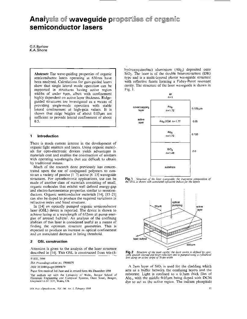
hydroxyquinoline) aluminium (Alq3) deposited onto SO2. The laser is of the double heterostructure (DH) type and is a multi-layered planar waveguide structure with reflective facets forming a Fabry-Perot resonant cavity. The structure of the laser waveguide is shown in Fig. 1.
air n= l
7 cover/capping I Ah3
layer
active layer
I n=1.72
Alq3:DCM n=1.77
n=1.72
SiO, n=1.46
I substrate
0.125prn
0.05
D.125
2.0
Fig. I the OSL is shown with associated refractive indices for the layers
Structure of the laser waveguide; the transverse composition of
I optical
la
Fi .2 Structure o the laser cavity; the laser cavity is defined by opti- cajy smooth cleaveAnd facet reflectors and is pumped using a cylindrical lens along an active stripe of 5 0 ~ width
A 2p-1 layer of SiOz is used for the cladding which acts as a buffer between the confining layers and the substrate. Light is confined to a 0 . 3 p thick film of Alq,, with the middle 0 . 0 5 ~ being doped with DCM dye to act as the active region. The indium phosphide
15 IEE Proc.-Optoelectron., Vol. 146, No. 1. February 1999

(InP) substrate was cleaved along parallel planes prior to deposition of the waveguide layers. As successive films are added, their shape conforms to the underlying substrate, producing end facets with a reported reflec- tivity of 0.07.
The waveguide is optically pumped using a 337nm nitrogen laser focussed, using a cylindrical lens, onto a 50pm wide stripe perpendicular to the plane of the fac- ets. Lateral optical confinement is therefore achieved by gain-guiding. The structure of the laser cavity is shown in Fig. 2. The operating wavelength of the laser was reported at around 630nm, with a gain threshold of around 1 pJ/cm2.
3 Waveguide asnaUysis technique
The method used for the modal analysis of the OSL waveguide structures is a development of a technique described in [22-251 for the analysis of multi-layered waveguide structures with complex refractive indices.
In the standard matrix analysis of multi-layer wave- guide structures, solutions are sought as the eigen-val- ues of a transfer matrix connecting the amplitude coef- ficients of the field profile in the cover and substrate layers [22]. The matrix is derived from consideration of the matching of TE or TM fields and their derivatives at the interfaces between the homogeneous layers of the waveguide and the satisfaction of the Helmholtz wave equation describing propagation of light through the waveguide. Individual elements of the transfer matrix of a waveguide can then be used as explicit dispersion relation functions, the zeros of which correspond to bound or lossy modes depending on the choice of matrix element.
In order to locate the zeros of the dispersion relation, use is made of a novel technique described in [24]. This method first unfolds the solution space by means of a conformal mapping substitution:
U = JG+ JG (1) where ki and k i are the wave-numbers of the cover and substrate respectively, defined by kJ = n,k, where k is the free space wavenumber, given by k = 2nIA and nJ are the refractive indices of the modes. /3 is the propa- gation constant of the waveguide, and is the independ- ent variable of the dispersion function prior to the unfolding, and U is the new independent variable after the unfolding. This mapping projects the multi-valued ,f3 space onto a single imaginary plane of the variable U. This approach offers advantages in the ease with which solutions can be tracked across the solution space. The location of solutions in the complex U plane indicates the nature of the modes represented. This dependence is discussed in detail in [24]. It is then pos- sible to approximate the location of the solutions by evaluating the following integral around the region of interest, after [23]:
(2) 1 f' ( U ) dU s - - Urn-
- %% h f ( U ) where f l v ) and f'( U> are the dispersion relation and its derivative, respectively. By inspection of eqn. 2, if rn = 0 then So will simply be equal to the number of solutions within the region bound by the integral. The locations of the solutions are then obtained using Laguerre's method as solutions to the polynomial:
,
p ( z ) = clul + czu2 + c3u3 + * * . + CS,US" (3)
where the locations of the zeros offlcr> are written as U, where i = 1, 2, ..., So. The coefficients C, are found using the recurrence relation
k
(4)
Once the polynomial in eqn. 3 is solved for the values U',2 the propagation constant and effective index can be found via eqn. 1.
Although the technique proves reliable as a means of obtaining solutions to the dispersion relation within a given region, it has been observed that the accuracy of the approximation polynomial may vary with differing waveguide configurations, layer numbers and sizes of contour. Decreasing the integration step can improve accuracy but at the expense of computing time. To overcome this, an additional routine is included to per- form a simple 'downhill' iterative search algorithm using the solutions given by the approximation polyno- mial as initial guesses. The hybrid program proves to be very robust and gives solutions to defined accuracy. In addition, the program requires no further input once waveguide parameters have been specified. TM modes may be found by considering the usual TM boundary conditions. The only difference in the calculation of TM modes is thus seen in the ml layer matrices.
Once the solutions to the dispersion relation have been found, the values for the propagation constant may be substituted into the wave equation to give the field profile of the modes.
4
It is advantageous in the design of laser devices to restrict the output to a single guided mode. As the structure described above is a two-dimensional waveguide, the effective index approximation [25] is used to find the modes of the laser. The exact mecha- nism of optical excitation in organic materials is not well known and the relationship between the pump energy and the exponential gain coefficient, g , is uncer- tain. However, it is possible to calculate the modal gain threshold from the cavity losses of the laser. The modal gain threshold of the OSL can be estimated using
Mode anaaOysis off the OSL
1 1 y = -In - + a L R (5)
where L is the length of the cavity, R is the reflectivity of the end mirrors and a represents the material losses. y the modal gain is defined as y = grxy where Txy is the optical confinement of the two-dimensional waveguide.
Assuming Try to be unity, the threshold gain can obviously be calculated directly from eqn. 5. The imag- inary part of the refractive index of the active region of the OSL can then be obtained from the gain threshold in the active region using the standard expression
9 Im(n) = - 2k
As is well known, between two materials of refractive index n1 and n2, the reflectivity of the interface is given by:
(7 )
For the end facets of the OSL, where nl = 1.7 and n2 - 1, then a reflectivity of around 7% is expected, as reported in [14]. Using this value in eqn. 5 for a laser of
16 IEE Proc-Optoelectron , Vol 146, No. 1. February 1999
length 500pm, results in a gain value of g = 53cm-1 and a value for the imaginary refractive index of Im(n) = 2.7 x lo4.
Bulk material losses in organic materials are typically in the region of Q - O.lcm-', as this is much smaller than the calculated values for the active gain, these losses are assumed to be negligible.
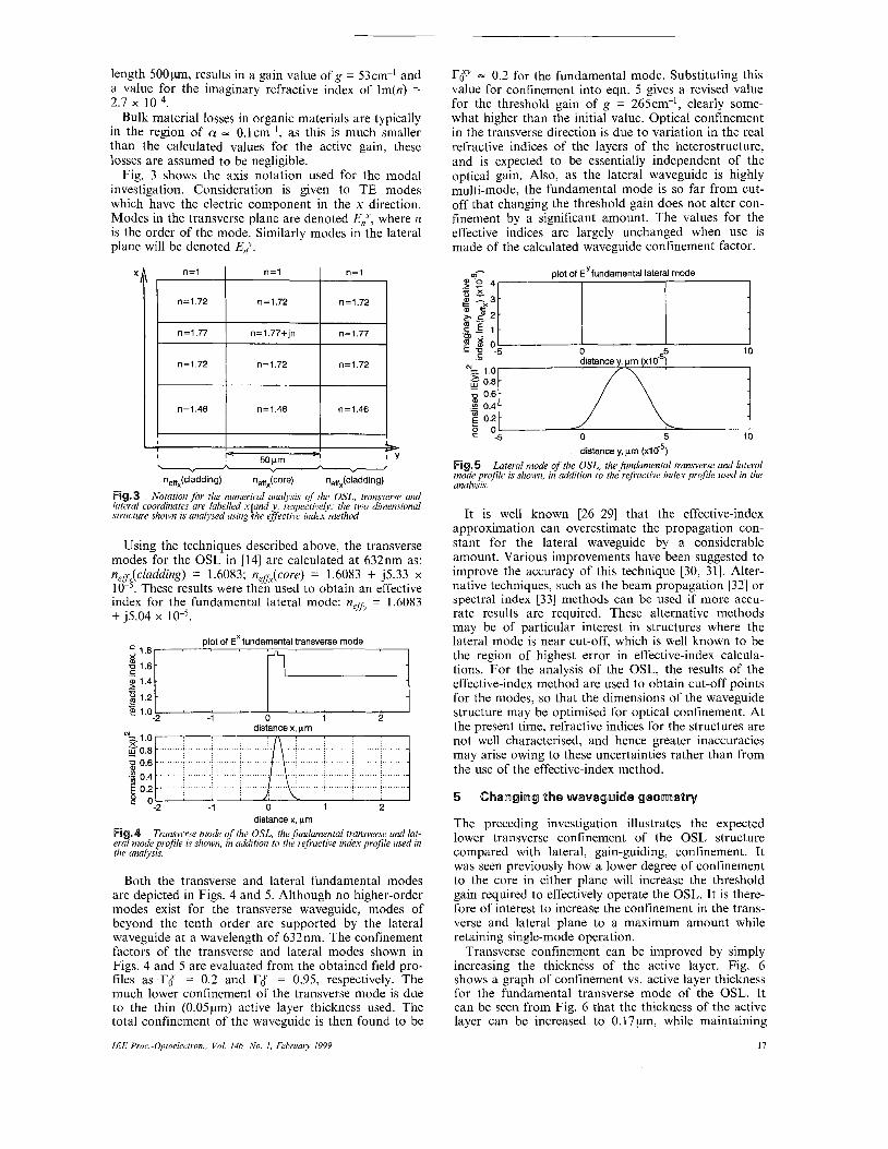
Fig. 3 shows the axis notation used for the modal investigation. Consideration is given to TE modes which have the electric component in the x direction. Modes in the transverse plane are denoted E,", where n is the order of the mode. Similarly modes in the lateral plane will be denoted E,L.
rgy = 0.2 for the fundamental mode. Substituting this value for confinement into eqn. 5 gives a revised value for the threshold gain of g = 265cm-', clearly some- what higher than the initial value. Optical confinement in the transverse direction is due to variation in the real refractive indices of the layers of the heterostructure, and is expected to be essentially independent of the optical gain. Also, as the lateral waveguide is highly multi-mode, the fundamental mode is so far from cut- off that changing the threshold gain does not alter con- finement by a significant amount. The values for the effective indices are largely unchanged when use is made of the calculated waveguide confinement factor. XI I n=i I n = i I n = i ,
n=1.72 n=1.72 n=1.72
n=1.77 n=1.77+jn n=1.77
n=1.72 n=1.72 n=1.72
n=1.46 n=1.46 n=1.46
I I 5- I P 9 I Y 50 pm
neffx(cladding) neffx(core) neffx(cladding) \ ,. ,. " " " I
Fig.3 Notation for the numerical analysis of the OSL, transverse and lateral coordinates are labelled xiland y , respectively; the two dimensional structure yhown is analysed using rhe efjective index method
Using the techniques described above, the transverse modes for the OSL in [14] are calculated at 632nm as: nefipladding) = 1.6083; n,fiy(coYe) = 1.6083 + j5.33 x 10- . These results were then used to obtain an effective index for the fundamental lateral mode: nCffv = 1.6083 + J5.04 x
=. 1.8 plot of EX fundamental transverse mode
1.6
1.4
3 1.2 c .- 2 1.0 -2 I -1 distance 0 x, pm 1 2
-1 0 1 2 distance x, pm
Fi .4 Transverse niode of the OSL, the fundamental transverse and lat- e r 3 mode profile is shown, in uddition to the refractive index profile used in the analysis.
Both the transverse and lateral fundamental modes are depicted in Figs. 4 and 5. Although no higher-order modes exist for the transverse waveguide, modes of beyond the tenth order are supported by the lateral waveguide at a wavelength of 632nm. The confinement factors of the transverse and lateral modes shown in Figs. 4 and 5 are evaluated from the obtained field pro- files as r,f = 0.2 and r{ = 0.95, respectively. The much lower confinement of the transverse mode is due to the thin ( 0 . 0 5 ~ ) active layer thickness used. The total confinement of the waveguide is then found to be
IEE Pror -Optoebctron, Vol 146 No I , February 1559
distance y, pn (xla5)
Fig.5 Lateral mode of the OSL, the fundamental transverse and lateral mode profile is shown, in addition to the refractive index profile used in the analysis.
It is well known [26-291 that the effective-index approximation can overestimate the propagation con- stant for the lateral waveguide by a considerable amount. Various improvements have been suggested to improve the accuracy of this technique [30, 311. Alter- native techniques, such as the beam propagation [32] or spectral index [33] methods can be used if more accu- rate results are required. These alternative methods may be of particular interest in structures where the lateral mode is near cut-off, which is well known to be the region of highest error in effective-index calcula- tions. For the analysis of the OSL, the results of the effective-index method are used to obtain cut-off points for the modes, so that the dimensions of the waveguide structure may be optimised for optical Confinement. At the present time, refractive indices for the structures are not well characterised, and hence greater inaccuracies may arise owing to these uncertainties rather than from the use of the effective-index method.
5 ChaUlgiUlg flh@ WaWgUide geQm@fIUt(
The preceding investigation illustrates the expected lower transverse confinement of the OSL structure compared with lateral, gain-guiding, confinement. It was seen previously how a lower degree of confinement to the core in either plane will increase the threshold gain required to effectively operate the OSL. It is there- fore of interest to increase the confinement in the trans- verse and lateral plane to a maximum amount while retaining single-mode operation.
Transverse confinement can be improved by simply increasing the thickness of the active layer. Fig. 6 shows a graph of confinement vs. active layer thickness for the fundamental transverse mode of the OSL. It can be seen from Fig. 6 that the thickness of the active layer can be increased to 0.17 pm, while maintaining
17

single-mode operation. This improves confinement to around 0.5. Calculations show that such a change in width would give the following modal characteristics: ne3(cludding) = 1.6678; neffx(core) = 1.6678 + j1.534 x 10 ; r,f = 0.54. These results were then used to obtain an effective index for the fundamental lateral mode: nefi = 1.6678 +j1.513 x
onset of first order mode
0.55
0,30/ 0.25 / 0 . 2 0 v , , , , , , , I , , , 1
0.06 0.08 0.10 0.12 0.14 0.16 0.18 0.20 0.22 0.24 active layer thickness, prn
Fig. 6 . Effect of varying active layer thickness on transverse confinement; the cut-in of the first-order mode is shown at U active layer thickness of about 0.18pm. Confinement is thus increased to about 0.5
Higher-order bound modes also exist for the lateral waveguide given in this configuration, however, con- finement of the fundamental mode is high: I'J = 0.99. The overall confinement for the fundamental mode of the waveguide is therefore calculated as: T X y = 0.54. When used in eqn. 5, this gives a value for the thresh- old gain of g = 98cm-', a significant decrease from the initially estimated value of 265cm-'.
Lateral optical confinement in the OSL is provided by gain-guiding as a result of optically pumping the laser. It has previously been shown that lateral waveguide operation is highly multi-mode and confine- ment of the fundamental approaches unity. The high confinement of multi-mode operation is of benefit to the efficiency of the laser and minimises the threshold gain. However, it is of interest to re-configure the laser for single-mode operation in the lateral direction whilst maintaining high confinement.
For various levels of gain, it was found that first- order-mode cut-in occurred when lateral confinement of the fundamental exceeded about 0.7. Choosing a minimum value for the lateral confinement of 0.6, the threshold gain required to operate the laser is, from eqn. 5: g = 164cm-'.
The confinement curve for the fundamental lateral mode at this level of gain is shown in Fig. 7(i). From the Figure, it can be seen that a pump beam width of about 6pm would be required for a single-mode opera- tion with a confinement of 0.6.
Optical pump beam widths of below a few tens of microns are physically difficult to achieve. Lowering the gain will reduce the imaginary effective index of the active stripe, and hence the confinement of the funda- mental will be optimum at broader pump widths.
The gain threshold can be lowered by increasing the reflectivity of the mirrors defining the laser cavity. High reflectivity is obtainable by the use of distributed Bragg reflectors (DBR), which may exhibit reflectivities in excess of 90% [34]. Recent reports show favourable results from DBR lasers with both Alq [35] and conju- gated polymer [36] gain media. Using a typical value of
18
90% for the reflectivity, R, in eqn. 5 gives a threshold gain value of 4cm-' for the OSL with an assumed min- imum confinement factor of 0.6. The effect on confine- ment of this much lower gain threshold can be seen in Fig. 7(ii). The active stripe width at which the optical confinement reaches 0.6 is shown to be around 4 0 ~ 1 , a significantly more physically realisable stripe width.
I 0.7
0.6 1 0.51
CI 0.5
0 1 10 10
active stripe width, prn (log scale)
Fig.7 Eflect of varying active layer width on lateral confinement: for an assumed confinement of 0.6 at the lasing threshold, the confinement curves are shown for the OSL defined by cleaved end facet reflectors (i). and for an OSL defined by reflectivities of 90% (ii). a value typical of using distrib- uted feed-back (DFB)
It is recognised that the lateral optical pump profile across the active region will not give rise to an abrupt step in the imaginary part of the neffx. values between the bulk material and the active region. It is to be expected that the intensity of the pump beam will fol- low, for example, a Gaussian profile. This will manifest itself as an increase in Im(n) toward the centre of the waveguide and a corresponding decrease toward the edges of the pump stripe. Accuracy of the analysis may therefore be improved by adopting a multi-layer struc- ture for the lateral waveguide having increasing values of the imaginary index toward the centre of the active region. Application of this technique, using a simple three-layer approximation for the core of the lateral waveguide, shows that, although confinement is improved by the use of a more realistic pumping pro- file, the cut-in points of the higher-order modes lie beyond the optimised values suggested in the above analysis.
Fig.8 Structure f the ridgeguide laser: in this configuration, lateral uiding is achieved y increasing the thickness o the cappin la er, and
fence the effective index, over the active region (& denotes t ie &erence in thickness over the active stripe)
IEE Proc-Optoelectron., Vol. 146, No. I, February 1999

6 Designing a rkdge-guide OSL
To increase the lateral confinement of the OSL while retaining single-mode operation, a ridge-guiding config- uration (Fig. 8) can be employed. Fig. 9 shows how the effective index of the transverse mode E$ varies as the capping thickness is increased by Ah. An optimised active layer thickness of 0.15 P is assumed.
1.674 -
1.672
1.670 -
- x s
m V
m .C 1.668 -
, p 1.666 - .- c
F
0 0.01 0.02 0.03 - 0.04 0.05 0.06 0.07
Ah, vn Fig.9 Effect of varying capping thickness on the effective index of the ,fiin&mental transverse mode (the cut-in point of the first-order mode is shown at dh = 0 . 0 3 6 ~ )
0.55 -
0.50 - 0.45 -
0 0.01 0.02 0.03 0.04 Ah, prn
Confinement vs. change in ca ping thickness (dh) for the EJ Fig.10 mode, showing optimum confinement o f 8 5 at dh = 0 . 0 2 5 ~
From Fig. 9, it is seen that for capping thicknesses greater than FJ 0 . 0 4 ~ , the waveguide structure becomes multi-mode in the transverse direction. Fig. 10 shows the effect of varying the capping layer thickness on lateral confinement. Choosing a required lateral confinement of I? = 0.5, it can be seen from Fig. 10 that Ah = 0 . 0 2 5 ~ is required. I? > 0.5 is possible with this configuration, but may lead to multi-mode opera- tion in the transverse coordinate.
The lateral pump profile will have little effect on the wave-guiding action of the ridge-guided design. The differences in the imaginary index are small compared with the imposed change in the effective index due to the ridge and are negligible in the analysis. The guiding action is therefore not affected by changes in gain val- ues.
7 Conclusion
In the above analysis, the OSL design suggested in [14] has been optimised in terms of optical confinement. The effects of using both gain-guided and ridge-guided
IEE Proc.-Optoelectron., Vol. 146. No 1. February I999
configurations for lateral confinement have been explored. It has been seen that the gain-guided struc- tures offer higher confinement, but require a significant reduction in gain for single-mode operation at larger pump beam widths.
Ridge-guided configurations provide comparable lat- eral confinement independent of gain. For an active region width of 1 P, optical confinement of 0.5 can be achieved by increasing the thickness of the capping layer by 0 . 0 2 5 ~ over the active area (Fig. 10).
The dependence of the threshold gain of a laser on confinement has been discussed. By improving optical confinement in such a structure, less pumping is required to achieve lasing. The most striking improve- ment in confinement was seen in the transverse mode. By increasing the active-layer thickness from 0.05 pm to 0.15 pm, the transverse confinement is increased from 0.2 to 0.5. Although this seems to suggest that there is a considerable advantage in increasing the active-layer thickness, it is recognised that practical problems such as imperfections in the growth of the Alq3/DCM film may inhibit this.
1 KANE, C.F., and KRCHNAVEK, R.R.: ‘Benzocyclobutene optical waveguides’, IEEE Photonics. Technol. Lett., 1995, 7, (5) ,
2 BROWN, K.S., TAYLOR, B.J., HORNACK, L.A., and WEI- DMANN, T.W.: ‘Characterization of poly(phenylsi1sesquioxane) thin-film planar optical waveguides’, IEEE Photonics. Technol. Lett., 1997, 9, (6), pp. 791-793
3 FISCHBECK, G., MOOSBURGER, R., TOPPER, M., and PETERMANN, K.: ‘Design concept for single-mode polymer waveguides’, Electron. Lett., 1996, 32, (3), pp. 212-213
4 VAN TOMME, E., VAN DAELE, P.P., BAETS, R.G., and LAGASSE, P.E.: ‘Integrated optic devices based on nonlinear optical polymers’, IEEE J. Quantum Electron., 1991, 27, (3), pp. 778-787
5 BOOTH, B.L.: ‘Low loss channel waveguides in polymers’, J. Lightwave Technol., 1989, 7, (IO), pp. 1445-1501
6 KNOCH, TH., MULLER, L., KLEIN, R., and NEYER, A.: Low loss polymer waveguides at 1300 and 1550 nm using halo-
genated acrylates’, Electron. Lett., 1996, 32, (14), pp. 12841285 PHELPS, C.W., BARRY, T.S., RODE, L., and KRCHNAVEK, R.R.: ‘Low-loss, single-mode, organic polymer waveguides utiliz- ing refractive index tailoring’, J. Lightwave Technol., 1997, 15, (9), pp. 1900-1905 FRA, S., KIMURA, T., SUHARA, T., and NISHIHARA, H.: An integrated-optic device using electrooptic polymer waveguide on Si substrate for modulating focus spot intensity distribution’, IEEE Photonics Technol. Lett., 1993, 5, (11) pp. 1291-1293
9 WEAVER, M.S., and BRADLEY, D.D.C.: ‘Organic electrolumi- nescent devices fabricated with chemical vapour deposited polya- zomethine films’, Synth. Met., 1996, 83, pp. 61-66
10 BRADLEY, D.: ‘Plastic lasers shine brightly’, Nature, 1996, 382, pp. 671
11 ONADA, M., CHUMA, A., NAKAYAMA, H., YAMAHAUE, T., TADA, K., and YOSHINO, K.: ‘Properties of light emitting diodes fabricated from self-assembled multilayer heterostructures of poly(p-pyridyl vinylene)’, J. Phys. D, Appl. Phys., 1997, 30, pp. 2364-2371
WARD, T.K., FEUER, M.D., and WILSON, W.L.: ‘Prospects for silicon monolithic opto-electronics with polymer light emitting diodes’, J. Lightwave Technol., 1994, 12, (12), pp. 21142121
3 WEAVER, M.S., LIDZEY, D.G., FISHER, T.A., PATE, M.A., O’BRIEN, D., BLEYER, A., TAJBAKHSH, A., BRADLEY, D.C., SKOLNICK, M.S., and HILL, G.: ‘Recent progress in pol- ymers for electroluminescence: microcavity devices and electron transport polymers’, Thin Solid Films, 1996, 273, pp. 3947
4 KOZLOV, V.G., BULOVIC, V., and FORREST, S.R.: ‘Temper- ature independent performance of organic semiconductor lasers’, Appl. Phys. Lett.. 1997, 71, (18), pp. 2575-2577
15 OHMORI, Y., MORISHIMA, C., FUJII, A., and YOSHI- NO, K.: ‘Electrical and optical properties of organic thin film multilayer structure and its application for electroluminescent diode’, IEICE Trans. Electron., 1994, E77-C, (5 ) , pp. 666671
16 OHMORI, Y., FUJII, A., UCHIDA, M., MORISHIMA, C., and YOSHINO, K.: ‘Fabrication and characteristics of 8-hydrox- yquinoline aluminiudaromatic diamene organic multiple quan- tum well and its use for the electroluminescent diode’, Appl. Phys. Lett., 1993, 62, (25), pp. 3250-3252
pp. 535-537
7
8
2 KIM, H.H., SCHWARTZ, R.G., OTA, Y., WOOD-
19

17 TADA, N., FUJII, A., OHMORI, Y., and YOSHINO, K.: ‘Mul- tjcolour organic electroluminescent device utilizing vapour-depos- ited flourescent dye films’, IEEE Trans. Electron Devices, 1997, 44, (8), pp. 1234-1238
18 OHMORI, Y., FUJII, A., UCHIDA, M., MORISHIMA, C., and YOSHINO, K.: ‘Observation of spectral narrowing and emission energy shift in organic electroluminescent diode utilizing 8-hydroxyquinoline aluminium/aromatic diamine multilayer struc- ture’, Appl. Phys. Lett., 1993, 63, (14), pp. 1871-1873
19 YOSHIDA, M., FUJII, A., OHMORI, Y., and YOSHINO, K.: ‘Three-layered multicolor organic electroluminescent device’, Appl. Phys. Lett., 1996, 69, (61, pp. 734-736
20 FUJII, A., YOSHIDA, M., OHMORI, Y., and YOSHINO, K.: ‘Polarization anisotropy of orgnic electroluminescent diode with periodic multilayer structure utilizing 8-hydroxyquinoline alumin- ium and aromatic diamine’, Jpn. J. Appl. Phys., 1995, 34, (2), pp.
21 GU, G., BURROWS, P.E., VENKATESH, S., and FOR- REST, S.R.: ‘Vacuum-deposited, nonpolymeric flexible organic light-emitting devices’, Opt. Lett., 1997, 22, (3), pp. 172-174
22 SHLERETH, K.H., and TACKE, N.: ‘The complex propagation constant of multilayer waveguides: an algorithm for a personal computer’, IEEE J . Quantum Electron., 1990, 26, (4), pp. 637-630
23 SMITH, R.E., HOUDE-WALTER, S.N., and FORBES, G.W.: Mode determination for planar waveguides using the four-
sheeted dispersion relation’, IEEE J. Quantum Electron., 1992, 28,
24 SMITH, R.E., HOUDE-WALTER, S.N., and FORBES, G.W.: Unfolding the multivalued planar waveguide dispersion relation’,
IEEEJ. Quantum Electron., 1993, 29, (4), pp. 1031-1034 25 CHIANG, K.S.: ’Analysis of rectangular dielectric waveguides:
effective-index method with built-in perturbation correction’, Electron. Lett.. 1992, 28, (4), pp. 388-390
26 LEE, J.S., and SHIN, S.Y.: ‘On the validity of the effective index method for rectangular dielectric waveguides’, J. Lightwave Tech- no/., 1993, 11, (8), pp. 1320-1324
L621-L624
(6), pp. 1520-1 526
27 CHIAN, K.s.: ‘Analysis of the effective-index method for the vector modes of rectangular-core dielectric waveguides’, IEEE Trans. Microw. Theory Tech., 1996, 44, (5), pp. 692-700
28 CHIAN, K.S.: ‘Performance of the effective-index method for the analysis of dielectric wave-guides’, Opt. Lett., 1991, 16, (lo), pp. 714-716
29 KUMAR, A., CLARK, D.F., and CULSHAW, B.: ‘Explana- tion of errors inherent in the effective-index method for analyzing rectangular-core waveguides’, Opt. Lett., 1988, 13, (121, PP. 1129- 1131
30 BENSON, T.M., BOZEAT, R.J., and KENDALL, P.C.: ‘Rigor- ous effective index method for semiconductor rib waveguides’, IEE Proc. J. Optoelectron., 1992, 139, (l), pp. 67-70
31 YOUNG, P.R., and COLLIER, R.J.: ‘Solution of lossy dielectric waveguides using dual effective-index method’, Electron. Lett., 1997, 33, (21), pp. 1788-1789
32 RASMUSSEN, T., POVLSEN, J.H., and BJARKLEV, A.: Improved two-dimensional beam propagation method for three
dimensional integrated-optic waveguide structures having rectan- gular-core cross sections’, Opt. Lett., 1994, 19, (15) pp. 1128- 1130
33 HONG, J., HUANG, W.P., and MAKINO, T.: ‘Modeling of ridge-waveguide MQW DFB lasers based on spectral index trans- fer matrix method’, IEEE J. Quantum Electron., 1993, 29, (6), pp. 1743-1750
34 CONVERTINO, A., VALENTINI, A., LIGONZO, T., and CONGLOLANI, R.: ‘Organic-morganlc dielectric multilayer sys- tems as high reflectivity distributed Bragg reflectors’, Appl. Phys. Lett., 1997, 71, (6), pp. 732-734
35 BERGGREN, M., DODABALAPUR, A., SLUSHER, R.E., TIMKO, A., and NALAMASU, 0.: ‘Organic solid-state lasers with imprinted gratings on plastic substrates’, Appl. Phys. Lett., 1998, 72, (4), pp. 410411
36 MCGHEHEE, M.D., DIAZ-GARCIA, M.A., HIDE, F., GUPTA, R., MILLER, E.K., and MOSES, D.: ‘Semiconducting polymer distributed feedback lasers’, Appl. Pliys. Lett., 1998, 72, (13), pp. 1536-1538
20 IEE Proc.-Optoelectron., Vol. 146, No. I , February I999