analysis of water vapor condensation on constellation ... thermal/peri... · october 24 2008...
TRANSCRIPT
October 24 2008
Analysis of Water Vapor Condensation on Constellation Space Suit System Connectors
Peri Sabhapathy
Siraj Jalali
Oceaneering Space Systems16665 Space Center Blvd.
Houston, TX 77058
TFAWS , Aug. 16-20, 2010
NEW SUIT
NEW TEAM
NEW JOURNEY
Objectives
• Develop a method to predict the water vapor
condensation rate from the humid ambient air onto a
cooled flat surface in a low gravity environment.
• Predict the water vapor condensation rate on
Constellation Space Suit System (CSSS) connector
surfaces for the worst case thermal conditions in the
cabin (Orion) during donning/doffing of the spacesuit
or a suited intra-vehicular activity (IVA).
2Oceaneering Space Systems
NEW SUIT
NEW TEAM
NEW JOURNEY
Constellation Space Suit System
3Oceaneering Space Systems
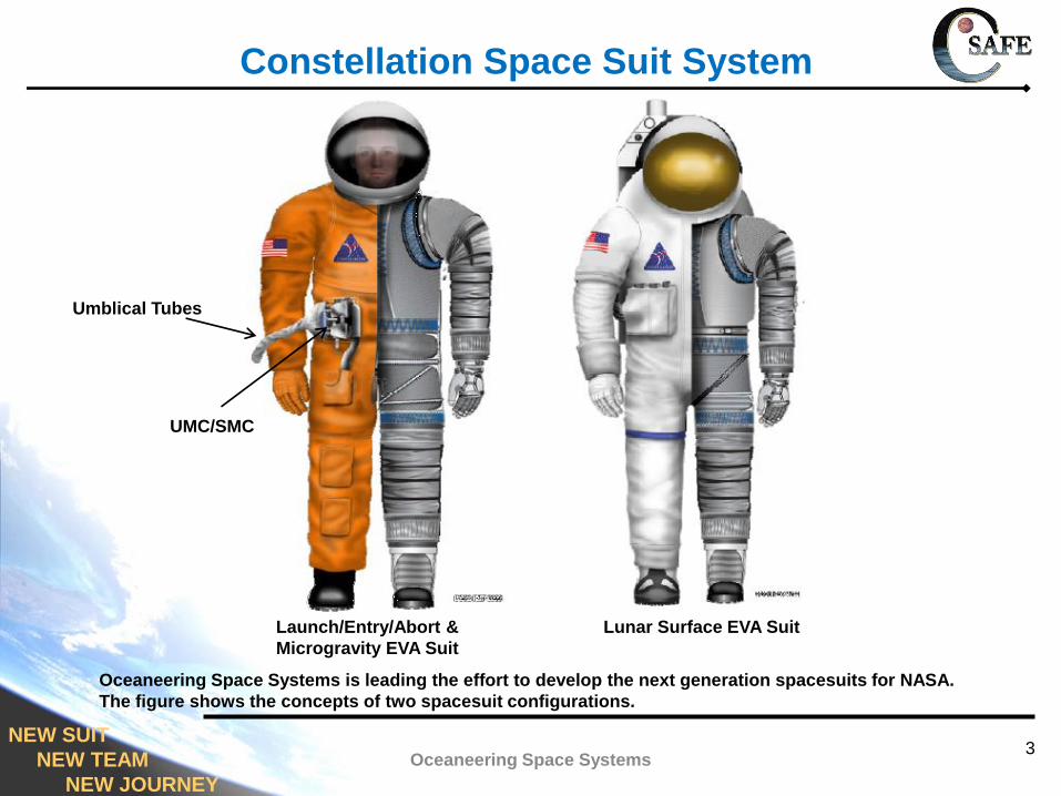
Launch/Entry/Abort &
Microgravity EVA Suit
Lunar Surface EVA Suit
Oceaneering Space Systems is leading the effort to develop the next generation spacesuits for NASA.
The figure shows the concepts of two spacesuit configurations.
Umblical Tubes
UMC/SMC
NEW SUIT
NEW TEAM
NEW JOURNEY
CSSS Suit Multiple Connector and
Umblical Multiple Connector
4Oceaneering Space Systems
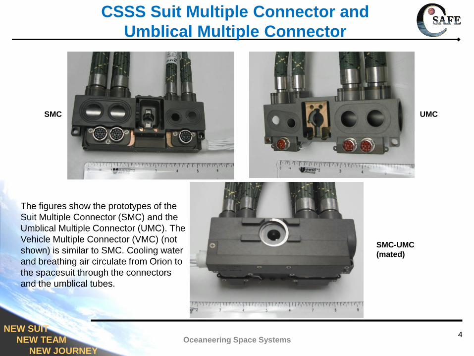
SMC UMC
SMC-UMC
(mated)
The figures show the prototypes of the
Suit Multiple Connector (SMC) and the
Umblical Multiple Connector (UMC). The
Vehicle Multiple Connector (VMC) (not
shown) is similar to SMC. Cooling water
and breathing air circulate from Orion to
the spacesuit through the connectors
and the umblical tubes.
NEW SUIT
NEW TEAM
NEW JOURNEY
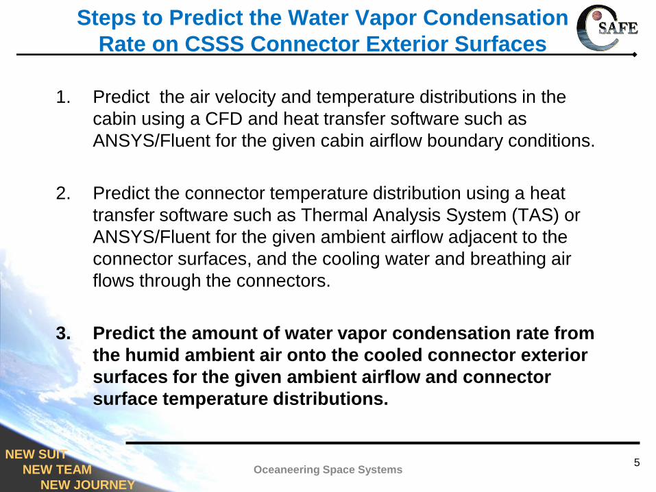
Steps to Predict the Water Vapor Condensation
Rate on CSSS Connector Exterior Surfaces
1. Predict the air velocity and temperature distributions in the
cabin using a CFD and heat transfer software such as
ANSYS/Fluent for the given cabin airflow boundary conditions.
2. Predict the connector temperature distribution using a heat
transfer software such as Thermal Analysis System (TAS) or
ANSYS/Fluent for the given ambient airflow adjacent to the
connector surfaces, and the cooling water and breathing air
flows through the connectors.
3. Predict the amount of water vapor condensation rate from
the humid ambient air onto the cooled connector exterior
surfaces for the given ambient airflow and connector
surface temperature distributions.
5Oceaneering Space Systems

NEW SUIT
NEW TEAM
NEW JOURNEY
Top
Typical Airflow Distribution in the Cabin
from a CFD Analysis
Airflow at the cabin
inlet=100 cfm.
6
NEW SUIT
NEW TEAM
NEW JOURNEY
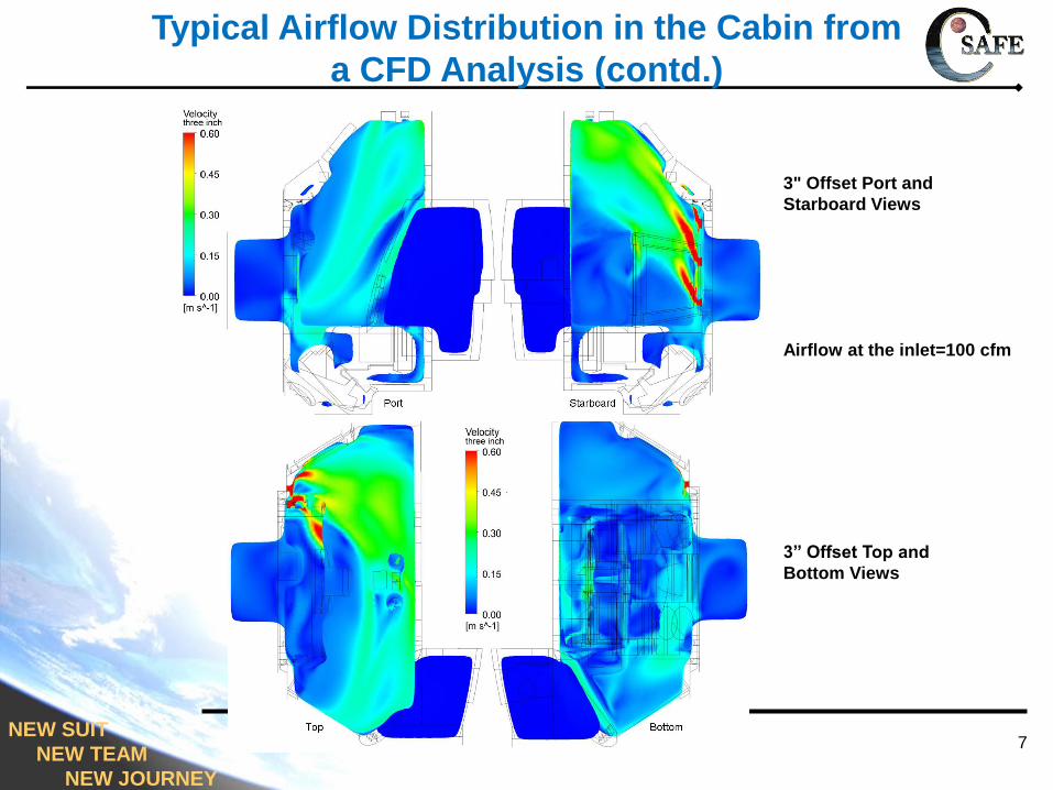
3" Offset Port and
Starboard Views
3” Offset Top and
Bottom Views
Typical Airflow Distribution in the Cabin from
a CFD Analysis (contd.)
Airflow at the inlet=100 cfm
7
NEW SUIT
NEW TEAM
NEW JOURNEY
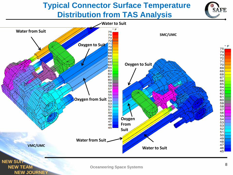
Typical Connector Surface Temperature
Distribution from TAS Analysis
Water to Suit
Water to Suit
Oxygen to Suit
Oxygen from Suit
Water from Suit
Water from Suit
Oxygen to Suit
OxygenFromSuit
VMC/UMC
SMC/UMC
8Oceaneering Space Systems
NEW SUIT
NEW TEAM
NEW JOURNEY
Condensate Rate Prediction Model Assumptions
• Crew cabin air is at standard composition and at 14.7 psi with a dew
point temperature of 55 oF (worst case).
• Connector is in a low-gravity environment, and, therefore, the
gravitational effects on the water vapor condensation are neglected.
• The airflow over the connector surfaces is laminar.
• The connector surfaces are assumed to be flat, and, therefore,
irrespective of the connector orientation, the analysis of water vapor
condensation on a cooled horizontal flat plate is valid for all the
exposed connector surfaces.
• The condensate is assumed to be thin and stagnant, and, is of
uniform thickness. (The drag due to the ambient airflow is neglected.)
• The liquid-vapor interface is assumed to be at saturation conditions.
• The condensate thickness on the wall is small (order of 1 mm).
• Water vapor condensation is mass transfer controlled.
9Oceaneering Space Systems
NEW SUIT
NEW TEAM
NEW JOURNEY
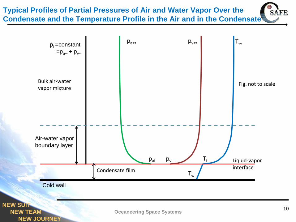
Typical Profiles of Partial Pressures of Air and Water Vapor Over the
Condensate and the Temperature Profile in the Air and in the Condensate
10Oceaneering Space Systems
Condensate film
Bulk air-water vapor mixture
Fig. not to scale
T∞pa∞ pv∞
pai pvi Ti
Tw
Liquid-vaporinterface
Air-water vapor
boundary layer
pt =constant
=pa∞ + pv∞
Cold wall
NEW SUIT
NEW TEAM
NEW JOURNEY
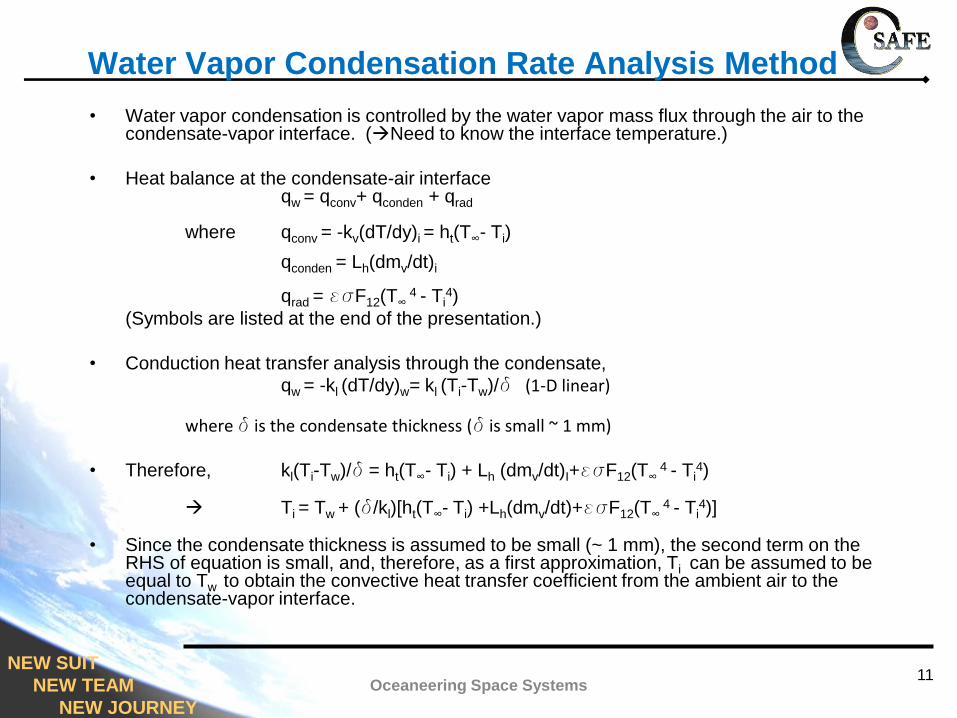
Water Vapor Condensation Rate Analysis Method
• Water vapor condensation is controlled by the water vapor mass flux through the air to the condensate-vapor interface. (Need to know the interface temperature.)
• Heat balance at the condensate-air interfaceqw = qconv+ qconden + qrad
where qconv = -kv(dT/dy)i = ht(T∞- Ti)
qconden = Lh(dmv/dt)i
qrad = esF12(T∞ 4 - Ti
4)
(Symbols are listed at the end of the presentation.)
• Conduction heat transfer analysis through the condensate,
qw = -kl (dT/dy)w= kl (Ti-Tw)/d (1-D linear)
where d is the condensate thickness (d is small ~ 1 mm)
• Therefore, kl(Ti-Tw)/d = ht(T∞- Ti) + Lh (dmv/dt)I+esF12(T∞ 4 - Ti
4)
Ti = Tw + (d/kl)[ht(T∞- Ti) +Lh(dmv/dt)+esF12(T∞ 4 - Ti
4)]
• Since the condensate thickness is assumed to be small (~ 1 mm), the second term on the RHS of equation is small, and, therefore, as a first approximation, Ti can be assumed to be equal to Tw to obtain the convective heat transfer coefficient from the ambient air to the condensate-vapor interface.
11Oceaneering Space Systems
NEW SUIT
NEW TEAM
NEW JOURNEY
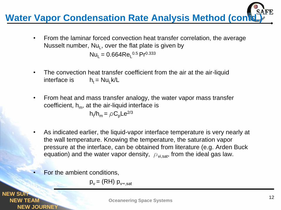
Water Vapor Condensation Rate Analysis Method (contd.)
• From the laminar forced convection heat transfer correlation, the average
Nusselt number, NuL, over the flat plate is given by
NuL = 0.664ReL0.5 Pr0.333
• The convection heat transfer coefficient from the air at the air-liquid
interface is ht = NuLk/L
• From heat and mass transfer analogy, the water vapor mass transfer
coefficient, hm, at the air-liquid interface is
ht/hm = rCpLe2/3
• As indicated earlier, the liquid-vapor interface temperature is very nearly at
the wall temperature. Knowing the temperature, the saturation vapor
pressure at the interface, can be obtained from literature (e.g. Arden Buck equation) and the water vapor density, rvi,sat, from the ideal gas law.
• For the ambient conditions,
pv = (RH) pv∞,sat
12Oceaneering Space Systems
NEW SUIT
NEW TEAM
NEW JOURNEY
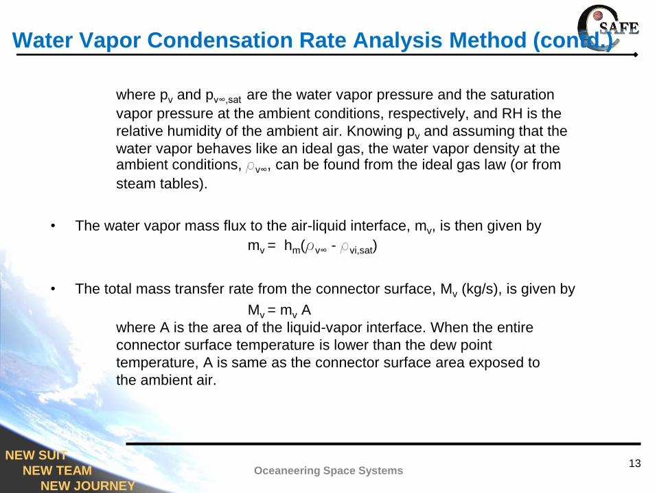
Water Vapor Condensation Rate Analysis Method (contd.)
where pv and pv∞,sat are the water vapor pressure and the saturation
vapor pressure at the ambient conditions, respectively, and RH is the
relative humidity of the ambient air. Knowing pv and assuming that the
water vapor behaves like an ideal gas, the water vapor density at the ambient conditions, rv∞, can be found from the ideal gas law (or from
steam tables).
• The water vapor mass flux to the air-liquid interface, mv, is then given by
mv = hm(rv∞ - rvi,sat)
• The total mass transfer rate from the connector surface, Mv (kg/s), is given by
Mv = mv A
where A is the area of the liquid-vapor interface. When the entire
connector surface temperature is lower than the dew point
temperature, A is same as the connector surface area exposed to
the ambient air.
13Oceaneering Space Systems
NEW SUIT
NEW TEAM
NEW JOURNEY
Water Vapor Condensation Rate Analysis Method (contd.)
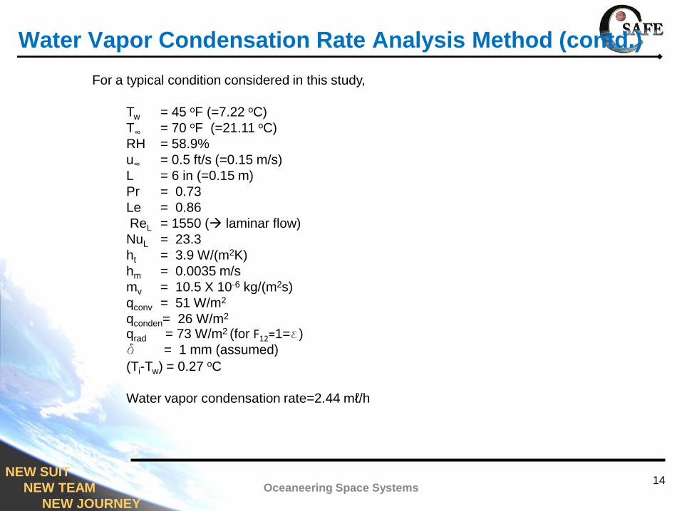
For a typical condition considered in this study,
Tw = 45 оF (=7.22 оC)
T∞ = 70 оF (=21.11 оC)
RH = 58.9%
u∞ = 0.5 ft/s (=0.15 m/s)
L = 6 in (=0.15 m)
Pr = 0.73
Le = 0.86
ReL = 1550 ( laminar flow)
NuL = 23.3
ht = 3.9 W/(m2K)
hm = 0.0035 m/s
mv = 10.5 X 10⁻⁶ kg/(m2s)
qconv = 51 W/m2
qconden= 26 W/m2
qrad = 73 W/m2 (for F12=1=e)
d = 1 mm (assumed)
(Ti-Tw) = 0.27 oC
Water vapor condensation rate=2.44 mℓ/h
14Oceaneering Space Systems
NEW SUIT
NEW TEAM
NEW JOURNEY
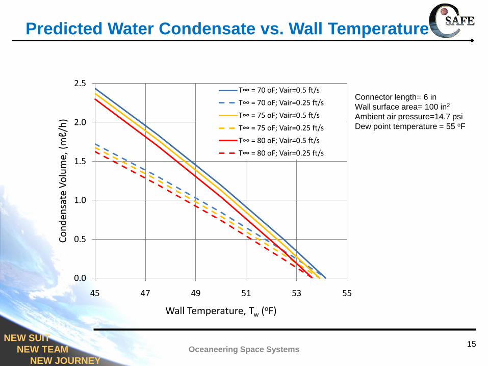
Predicted Water Condensate vs. Wall Temperature
15Oceaneering Space Systems
0.0
0.5
1.0
1.5
2.0
2.5
45 47 49 51 53 55
Co
nd
ensa
te V
olu
me,
(m
ℓ/h
)
Wall Temperature, Tw (oF)
T∞ = 70 oF; Vair=0.5 ft/s
T∞ = 70 oF; Vair=0.25 ft/s
T∞ = 75 oF; Vair=0.5 ft/s
T∞ = 75 oF; Vair=0.25 ft/s
T∞ = 80 oF; Vair=0.5 ft/s
T∞ = 80 oF; Vair=0.25 ft/s
Connector length= 6 in
Wall surface area= 100 in2
Ambient air pressure=14.7 psi
Dew point temperature = 55 oF
NEW SUIT
NEW TEAM
NEW JOURNEY
Conclusions
• A method to predict the water vapor condensation rate from the humid ambient air
onto a cooled flat surface in a low gravity environment was developed.
• The method was applied to predict the water vapor condensation on CSSS VMC,
UMC and SMC surfaces for the worst case thermal conditions in the cabin during
donning/doffing the spacesuit or a suited IVA.
• The water vapor condensation rate decreases with an increase in connector surface
temperature and a decrease in air velocity adjacent to the connector surface.
• The predicted water vapor condensation on a VMC/UMC or UMC/SMC combination
cooled with water at 45 oF in an ambient air at 70 oF with a dew point temperature of
55 oF was about 2.4 mℓ/h (or 58 mℓ/day).
• The method can be extended to predict water vapor condensation to similar
situations such as water vapor condensation over the cooled umbilical tubes so long
as the thickness of the condensate is small compared to the tube diameter.
16Oceaneering Space Systems
NEW SUIT
NEW TEAM
NEW JOURNEY
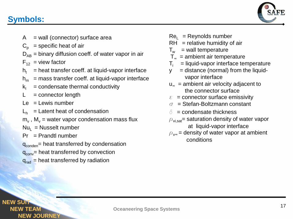
A = wall (connector) surface area
Cp = specific heat of air
DAB = binary diffusion coeff. of water vapor in air
F12 = view factor
ht = heat transfer coeff. at liquid-vapor interface
hm = mass transfer coeff. at liquid-vapor interface
kl = condensate thermal conductivity
L = connector length
Le = Lewis number
Lh = Latent heat of condensation
mv , Mv = water vapor condensation mass flux
NuL = Nusselt number
Pr = Prandtl number
qconden= heat transferred by condensation
qconv= heat transferred by convection
qrad = heat transferred by radiation
ReL = Reynolds number
RH = relative humidity of air
Tw = wall temperature
T∞ = ambient air temperature
Ti = liquid-vapor interface temperature
y = distance (normal) from the liquid-
vapor interface
u∞ = ambient air velocity adjacent to
the connector surfacee = connector surface emissivity
s = Stefan-Boltzmann constant
d = condensate thickness
rvi,sat= saturation density of water vapor
at liquid-vapor interfacerv∞ = density of water vapor at ambient
conditions
Symbols:
17Oceaneering Space Systems
NEW SUIT
NEW TEAM
NEW JOURNEY
Acknowledgements:
• The authors would like to thank the management of Oceaneering
Space Systems, and, in particular, Thomas Nguyen, Manager,
Engineering Analysis Department, for his constant encouragement
and support through the course of this study.
• The authors would also like to thank Julie Allen, Engineer, CSSS
Vehicle Interface Element, Oceaneering Space Systems, for the
cabin airflow analysis.
18Oceaneering Space Systems