analysis of soot and nox emissions reduction possibilities ... · zbog male brzine vrtnje. u radu...
TRANSCRIPT
Strojarstvo 52 (5) 525-533 (2010) T. SENČIĆ, Analysis of Soot and NOx Emissions Reduction... 525Analysis of Soot and NOx Emissions Reduction... 525 525
CODEN STJSAO ISSN 0562-1887 ZX470/1473 UDK 629.5.03-843.6:662.613:519.63(043)
Original scientific papirThe reduction of NOx and soot emissions are, besides improvement of fuel efficiency, the main goals of the development of modern diesel engines. The manufacturers of large marine engines are developing systems that allow great operation flexibility and different strategies that allow the mentioned goals. Except for experimental measurements, the computer simulation is a tool that is used for this scope. 3D numerical simulations are the most appropriate for the calculation of pollutant production. The large marine engines are specific for their size, fuel used, location of the injectors and small revolution rate.In the present work, a large marine engine model was developed with the OpenFOAM software toolbox. A heavy fuel oil and a soot model were built in. Spray model parameters were tuned. A set of different calculation meshes was tested. The model validation was performed on a constant volume combustion chamber, an automotive engine and, finally, on a large marine engine.After a satisfactory matching with experimental measurements, a set of numerical simulations was performed by which the possibility of emission reduction was evaluated. The strategies of scavenging air temperature reduction, exhaust gas recirculation and alternative injection patterns were used. After the end of the analysis all the methods resulted in a reduction of pollutant emissions.* Defended Doctoral Thesis (2010)
Analiza mogućnosti smanjenja emisija čađe i NOx na suvremenim sporohodnim dizelskim dvotaktnim motorima
Izvornoznanstveni članakSmanjenje emisija dušikovih oksida i čađe uz povećanje stupnja djelovanja glavni su ciljevi kod razvoja suvremenih dizelskih motora. Proizvođači velikih brodskih motora razvijaju sustave koji omogućuju veliku fleksibilnost u radu i različite strategije koje omogućuju postizanje spomenutih ciljeva. U tu svrhu se osim mjerenja koriste kompjutorske simulacije. Za proračun tvorbe štetnih tvari najprikladnije su 3D numeričke simulacije. Veliki brodski motor specifičan je zbog svojih dimenzija, zbog goriva koje koristi, zbog smještaja rasprskača te zbog male brzine vrtnje.U radu je razvijen model velikog brodskog motora pomoću OpenFOAM programskog kompleta alata. Ugrađen je model teškog goriva i model za čađu. Korigirani su parametri modela mlaza. Testiran je čitav raspon proračunskih mreža različitih karakteristika. Validacija je vršena na komori izgaranja konstantnog volumena, na vozilskom motoru i konačno na velikom brodskom motoru. Nakon što je postignuto zadovoljavajuće poklapanje s eksperimentalnim mjerenjima, izvršena je serija numeričkih simulacija pri čemu su analizirane mogućnosti smanjenja emisija. Korištene su strategije smanjenja temperature ispirnog zraka, recirkulacije ispušnih plinova te alternativnih strategija ubrizgavanja goriva. Sve analizirane metode rezultirale su smanjenjem emisije štetnih tvari.* Obranjena doktorska disertacija (2010.)
Tomislav SENČIĆ)
Tehnički fakultet Sveučilišta u Rijeci (Technical Faculty of the University of Rijeka), Vukovarska 58, HR-51000 Rijeka, Croatia
KeywordsEmissions Nitrogen oxides Soot Two stroke low-speed diesel engine 3D numerical simulation
Ključne riječiČađa Dušikovi oksidi Dvotaktni sporohodni dizelski motor Emisije 3D numerička simulacija
Received (primljeno): 2010-05-31 Accepted (prihvaćeno): 2010-08-31
Analysis of Soot and NOx Emissions Reduction Possibilities on Modern Low Speed, Two-Stroke, Diesel Engines*
1. Introduction
The fast growth of the world economy and transport causes a great energy demand. It results in different problems: it causes the shortage of fossil fuel followed by a price growth, and it has negative consequences on the environment and climate changes. Despite the many alternative energy sources, the diesel engine can still not
be replaced in transport. The big, slow speed, two stroke, diesel engines achieve fuel efficiency of over 0.5, making it more efficient than any other propulsion system. This means also the lowest carbon monoxide emission per power unit. The main problems which concern emissions from large marine engines are emission of nitric oxides and soot.

526 T. SENČIĆ, Analysis of Soot and NOx Emissions Reduction... Strojarstvo 52 (5) 525-533 (2010)
Symbols/Oznake
a - acceleration, ms-2
- ubrzanje
A - area, m2 - površina
C3 - model constant - konstanta modela
CD - drag koeficient - koeficijent otpora
F - force, N - sila
k - reaction rate coefficient - koeficijent brzine reakcije
m - mass, kg - masa
r - radius, m - polumjer
S - source term - izvorni član
t - time, s - vrijeme
T - Taylor number - Taylorov broj
u - velocity, ms-1 - brzina
V - velocity vector, ms-1 - vektor brzine
We - Webber number - Webberov broj
Z - Ohnesorge number - Ohnesorgeov broj
Γ - diffusion coefficient, m2s-1 - koeficijent difuzije
Λ - fastest growing wave length, m - duljina najbrže rastućeg vala
Π - Ludolph number, 3.14159 - Ludolphov broj
Ρ - density, kgm-3 - gustoća
Σ - surface tension, N/m - površinska napetost
Φ - general characteristic - općenita značajka
Ω - wave growth rate, ms-1 - brzina rasta vala
Ω - fastest wave growth rate, ms-1 - brzina najbrže rastućeg vala
Indices / Indeksi
0 - initial - početno
isp - evaporation - isparavanje
1 - liquid - tekući
g - gas - plinoviti
aero - aerodynamic - aerodinamički
rel - relative - relativno
The main large marine engine manufacturers have introduced technical innovations that allow a great flexibility. These are the “common rail” fuel injection system and the variable exhaust valve timing [1]. To carry out an analysis of the possibilities that these systems allow, besides experimental methods, the numerical simulations are used. For emission calculation 3D, CFD (Computational Fluid Dynamics) numerical simulation are the most appropriate [2-5], because the local temperature has the biggest influence on the chemical reaction rates. This kind of simulations is widely used for automotive engines. However, the large marine engines have some important differences. First of all, because of the big dimensions, the discretisation mesh cells have to be much bigger than in usual simulations. Then, the large marine engines are fuelled with HFO (Heavy Fuel Oil) which differs from the ordinary diesel fuel for
many physical characteristics [6]. For what concerns the geometry, the large marine engine has the exhaust valve in the central position and hence the injectors are located laterally. Finally, the revolution speed is different, which causes big differences in the available time for the processes. For these reasons, some different models and settings had to be developed.
For such purpose the CFD toolkit OpenFOAM [4] is very appropriate. It is a solver and library collection written in the C++ programming language. It is free and open source. For these reasons it is appropriate for development of new models and the solution of new problems.
Few authors have covered different parts of the subject of this paper. Tao [7] in his dissertation analyzes the formation of soot and nitrogen oxides in diesel engine conditions using complex chemical schemes, but is

Strojarstvo 52 (5) 525-533 (2010) T. SENČIĆ, Analysis of Soot and NOx Emissions Reduction... 527Analysis of Soot and NOx Emissions Reduction... 527 527
limited to applications in a constant volume combustion chamber and automotive diesel engine. Kralj [8] uses the method of computational fluid dynamics for the diesel engines process calculations but focuses on spray features and not emissions. Weisser [9] compares the capabilities of zero-dimensional and 3D modelling of the combustion process and formation of nitrogen oxides in the medium size marine engines. Lucchini et al. [10] contributes to the development of a new strategy for the mesh motion with variable topology and contributes to the development of OpenFOAM tools for the diesel engines analysis. Picket in a series of articles [11-13] reports detailed experimental measurements of the effects of various parameters on combustion and soot formation in a combustion chamber of constant volume.
In this work a heavy fuel oil model was developed, a soot model was built into OpenFOAM, different mesh configurations were tested and the fuel spray model parameters were modified. After having reached a satisfactory agreement with experimental measurements, the influence of strategies used to reduce soot and nitrogen oxides emissions, such as reducing scavenging air temperature, exhaust gas recirculation and different injection patterns, were analyzed.
2. Mathematical models
The diesel process is a complex system of interdependent phenomena that occur in the engine cylinder. Each of these phenomena is described by a separate submodel, Figure 1. Thus, the fuel properties model, the fuel injection model, the model of fuel spray break-up into drops, the fuel vaporization model, models of chemical reactions including the formation of nitrogen oxides, soot model and the turbulence model are used. All these models are linked because, for example, chemical reactions release heat which raises the temperature and pressure in the cylinder and this in turn strongly affects the properties of the fuel, jet break-up, evaporation and the chemical reactions [14].
2.1. Laws of conservation
The 3D numerical simulations are based on the laws of conservation. The conservation of mass is described by equation (1):
(1)
Figure 1. Scheme of the diesel processSlika 1. Shema dizelskog procesa

528 T. SENČIĆ, Analysis of Soot and NOx Emissions Reduction... Strojarstvo 52 (5) 525-533 (2010)
Similar equations are used to describe the momentum conservation in the 3 Cartesian coordinates and the conservation of energy. Since chemical reactions are analyzed, a similar equation is used to track the transportation of the single chemical species. In the simulations the RNG k-ε turbulence model is used, which uses similar equations too. All these equations have the same structure which can be described by equation (2):
(2)
The first term describes the change of the property in the time, the second term describes the property transport with the mechanism of convection. The first right hand side term describes the diffusion transport of the property and the last term stands for the source of the property. Since the equations describe the transport of a property in the domain they are sometimes called transport equations [15].
2.2. Spray model
The combined Blob-KH-RT model is used in the simulations in this work. The starting conditions of the first droplets at the nozzle hole exit of full cone diesel spray are defined by the blob method. The blob method is based on the assumption that atomization and drop break-up within the dense spray near the nozzle are indistinguishable processes, and that a detailed simulation can be replaced by the injection of big spherical droplets with uniform size, which are then subject to secondary aerodynamic-induced break-up. From the conservation of mass it follows the injection speed:
(3)
The Kelvin-Helmholtz model (KH model) is based on a first order linear analysis of a Kelvin-Helmholtz instability growing on the surface of a cylindrical liquid jet with initial diameter 2r0 that is penetrating into a stationary incompressible gas with a relative velocity urel.
Due to the turbulence in the nozzle hole the jet surface is covered with sinusoidal, axisymetric surface waves. These surface waves grow because of aerodynamic forces due to the relative velocity between liquid and gas. It is assumed that the wave with the highest growth rate ω = Ω will finally be sheared off the jet and form new droplets. After a detailed analysis [16], the speed of the fastest growing surface wave
(4)
and its wavelength
(5)
can be found.The RT (Rayleigh-Taylor) break-up mechanism
describes the catastrophic break-up mode which occurs when high relative velocities result in strong deceleration. The disintegration of the drop is induced by inertia of the liquid if drops and ligaments leaving the nozzle with high velocities are strongly decelerated by the aerodynamic drag force.
(6)
Dividing the drag force by the mass of the drop, the acceleration of the interface can be found,
(7)
where cD is the drag coefficient of the drop. The growth rate and the corresponding wavelength of the fastest growing wave are:
(8)
and
(9)
Further details of the used spray model can be found in [14, 16].
2.3. Heavy Fuel Oil Model
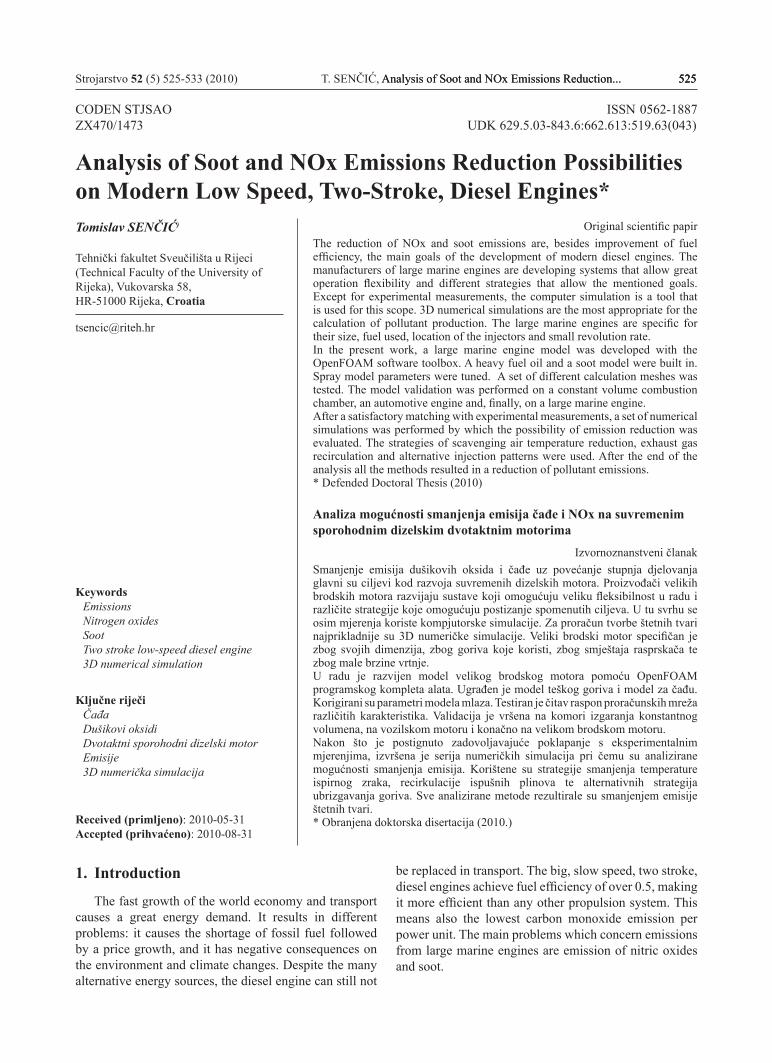
Heavy Fuel Oil (HFO) properties differ from those of the diesel fuel for density, viscosity, surface tension and many other which influence spray break-up and mixture formation. The properties of HFO were found in [6]. The properties in function of temperature were modelled with the use of NSRDS functions. A HFO model was built into OpenFOAM. In Figure 2, viscosity in function of temperature is presented for the HFO and for diesel fuel.
The NSRDS1 function used to fit the HFO viscosity values is also presented in the figure. The same process has been done for all the other fuel properties.
To simulate the evaporation process the standard OpenFOAM evaporation model was used. In order to simulate the chemical reactions, different chemical schemes were used. The schemes with their main properties are presented in Table 1.
Strojarstvo 52 (5) 525-533 (2010) T. SENČIĆ, Analysis of Soot and NOx Emissions Reduction... 529Analysis of Soot and NOx Emissions Reduction... 529 529
Figure 2. Fuel viscosity temperature dependenceSlika 2. Ovisnost viskoznosti goriva o temperaturi
Since it is considered that more than 90 % of the created NOx in the engine is the so-called thermal NO, the Zeldovich mechanism is used to simulate it:
N2 + o ←→No + N (10)
N + o2 ←→No + o (11)
N + OH ←→No + H (12)
For soot formation, a modified version of the Fusco model [17] was used. The modifications consist in the addition of pressure influenced reaction rate coefficients in order to improve the model reaction to pressure variations. Further details on the soot model, its implementation and modifications can be found in [14, 17-18].
Table 1. The used chemical schemes and the main propertiesTablica 1. Korištene kemijske sheme i njihove osnovne karakteristike
Name/ Ime n. species/ br. sastojaka
n. reactions/ br. reakcija
NO C2H2 OH
1 5 1 no no no15 15 39 yes no yesfull 56 290 yes yes yeskeck 36 68 yes no yesPatel-Reitz-C2H2 33 76 yes yes yesLiu-Pitsch-Peters 44 112 no yes yes
3. Validation
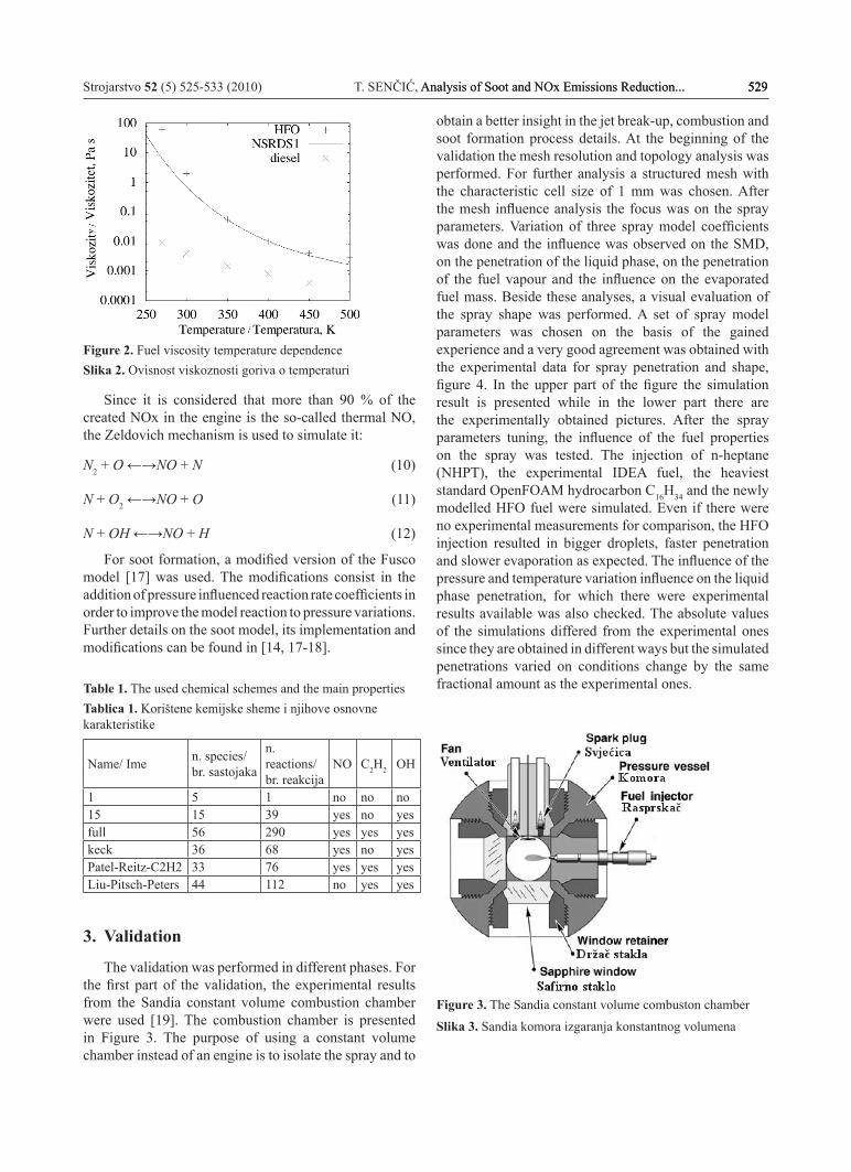
The validation was performed in different phases. For the first part of the validation, the experimental results from the Sandia constant volume combustion chamber were used [19]. The combustion chamber is presented in Figure 3. The purpose of using a constant volume chamber instead of an engine is to isolate the spray and to
obtain a better insight in the jet break-up, combustion and soot formation process details. At the beginning of the validation the mesh resolution and topology analysis was performed. For further analysis a structured mesh with the characteristic cell size of 1 mm was chosen. After the mesh influence analysis the focus was on the spray parameters. Variation of three spray model coefficients was done and the influence was observed on the SMD, on the penetration of the liquid phase, on the penetration of the fuel vapour and the influence on the evaporated fuel mass. Beside these analyses, a visual evaluation of the spray shape was performed. A set of spray model parameters was chosen on the basis of the gained experience and a very good agreement was obtained with the experimental data for spray penetration and shape, figure 4. In the upper part of the figure the simulation result is presented while in the lower part there are the experimentally obtained pictures. After the spray parameters tuning, the influence of the fuel properties on the spray was tested. The injection of n-heptane (NHPT), the experimental IDEA fuel, the heaviest standard OpenFOAM hydrocarbon C16H34 and the newly modelled HFO fuel were simulated. Even if there were no experimental measurements for comparison, the HFO injection resulted in bigger droplets, faster penetration and slower evaporation as expected. The influence of the pressure and temperature variation influence on the liquid phase penetration, for which there were experimental results available was also checked. The absolute values of the simulations differed from the experimental ones since they are obtained in different ways but the simulated penetrations varied on conditions change by the same fractional amount as the experimental ones.
Figure 3. The Sandia constant volume combuston chamber
Slika 3. Sandia komora izgaranja konstantnog volumena

530 T. SENČIĆ, Analysis of Soot and NOx Emissions Reduction... Strojarstvo 52 (5) 525-533 (2010)
Figure 4. Visual comparison of the spray simulation results and experimentally obtained spraySlika 4. Vizualna usporedba rezultata simulacije mlaza i eksperimentalno dobivenog mlaza
Further, combustion simulations were done. The influence of different chemical schemes reported in table 1. was tested. The simpler schemes with less reactions and species proved to be faster and more stable. However the more complex ones were necessary in order to obtain the calculation of the NO formation. In comparison with the experimentally measured pressure rise, the different schemes resulted in variable precision. The more complex schemes overpredicted the pressure rise. However, all the pressures missed the experimental pressure rise by maximally 2.7 %. The scheme that calculates the concentrations of 15 species was chosen as the best compromise for speed and precision and the fact that it has the NO chemistry included. At the end of the constant volume analysis, different soot models were tested. The Fusco model gave the best results. The spatial distribution, the duration and the concentration of the soot cloud obtained with this model were closest to the experimental measurements, Figure 5.
Figure 5. Various soot models comparison with experimentSlika 5. Usporedba različitih modela tvorbe čađe sa eksperimentom
The second part of the validation of the models was done for the automotive diesel engine MAN D 0826LOH15 for which experimental measurements were available. The mesh configuration and chemical scheme influence was tested. A mesh that involves 1 of the 7 jets (51 degree) was selected for further simulations. The scheme that calculates 15 species was confirmed as the best compromise too.
Figure 6. Simulated cylinder pressure compared with experimentally obtainedSlika 6. Simulirani tlak u cilindru u usporedbi s eksperimentalno dobivenim

Strojarstvo 52 (5) 525-533 (2010) T. SENČIĆ, Analysis of Soot and NOx Emissions Reduction... 531Analysis of Soot and NOx Emissions Reduction... 531 531
Then the simulation for different operating points was performed in order to confirm that the model is able to reproduce the pressure and emissions for different boundary conditions. A good matching with experimental data is obtained for the cylinder pressure, figure 6. The differences are attributed to the injection pressure history imperfection and to fuel property differences. For what concerns the NO emissions, a good matching was obtained for different operation points, figure 7. The absolute values match with an acceptable error. The change in emissions resulting from the change in speed and load is also well reproduced. The absolute values of soot emission levels are not simulated well, since the resulting simulated soot levels are several times higher than the experimental ones. However, the change of operation point to results in similar trends for the simulated soot emission as for the experimental one. So it can be said that the simulation model is efficient for NO calculations and for soot emission a trend analysis.
Further, to check the reaction of the engine simulation to the change of boundary conditions, the following analyses were performed: the influence of the injected fuel mass, revolution speed, the angle between the fuel spray and the cylinder head, and various injection strategies. The simulation results matched the expectations.
Figure 7. Simulated NO concentration compared to the experimentalSlika 7. Simulirani NO u usporedbi sa eksperimentalnim
4. Application of model to the large marine engine
After validation of the model on an automotive engine, the large marine engine model was built. The simulations are done for two engines: MAN 6S50 MC and Wärtsillä RT-flex50. In the first phase, the calculation mesh was built. Several mesh configurations and resolutions were considered. It was seen that the calculation mesh has a
great influence on the fuel evaporation and on the fuel vapour distribution. Finally, an unstructured mesh with 45 000 cells, Figure 8, was selected as the best compromise between calculation duration, cylinder pressure matching with experiment and fuel vapour cloud shape.
Figure 8. Large marine engine calculation meshSlika 8. Proračunska mreža velikog brodskog motora
After the mesh, the spray model settings had to be tuned in order to take account of the big dimensions. The model parameters were modified in order to allow a reasonable fuel evaporation and a realistic fuel vapour distribution in the cylinder. The distribution of the fuel vapour concentration, the local temperature distribution, the position of the high soot concentration and the position of the high NO concentration were observed. In Figure 9, the spray and the high NO concentration regions are showed. Further, the cylinder integral value for the total fuel vapour mass fraction, heat release speed, cylinder pressure, cylinder temperature, NO mass fraction and soot volume fraction were analyzed.
Figure 9. Fuel spray and the high NO concentration regionSlika 9. Mlaz goriva i područje visoke koncentracije NO

532 T. SENČIĆ, Analysis of Soot and NOx Emissions Reduction... Strojarstvo 52 (5) 525-533 (2010)
Figure 10. Cylinder pressure simulation for different fuels compared to the experimentalSlika 10. Simulacija tlaka u cilindru za različita goriva u usporedbi s eksperimentom
After the spray tuning, the influence of the combustion of different fuels was analyzed. The IDEA fuel, the C16H34 and the HFO fuels were analyzed, figure 10. The cylinder pressure was matched very well for the HFO fuel. The simulated NO mass fraction at the end of the process results in 0.00177 kg/kg which equals 13.5 g/kWh. The same value was measured experimentally. Finally, the analysis of three strategies to reduce the pollutant emissions was performed. The simplest strategy is the reduction of the scavenging air temperature. The results for three different scavenging temperatures are summarized in table 2. According to the simulations, both NO and soot emissions can be reduced without a reduction of the indicated work. In table 3, the results of the exhaust gas recirculation are presented. A very big NO emission reduction can be achieved with a small reduction of soot emission. However, this technique causes a small indicated work reduction which means a fuel efficiency decrease. The last technique consists in various injection strategies. The results are summarized in table 4. This strategy is mostly intended for soot reduction. This is shown by the results too. NO is reduced by a smaller fraction. The fuel efficiency is reduced too.
Table 2. Summary of the influence of the scavenging air temperature on the emissionsTablica 2. Sažetak utjecaja temperature ispirnog zraka na emisije
T, °C NO, kg NO, % Soot / Čađa, cm3 Soot/ Čađa, % Indicated work/ indicirani rad, KJ
Indicated work / Indicirani rad, %
40 0.00177699 - 4.1137·10-5 - 1828.0 -35 0.00170046 - 4.3 % 3.8779·10-5 - 5.7 % 1828.1 030 0.00162742 - 8.4 % 3.6014·10-5 - 12.5 % 1828.3 0
Table 3. Summary of the influence of exhaust gas recirculation on the emissions Tablica 3. Sažetak utjecaja recirkulacije ispušnih plinova na emisije
EGR NO, kg NO, % Soot / Čađa, cm3 Soot / Čađa, % Indicated work/ indicirani rad, KJ
Indicated work/ Indicirani rad %
0 % 0.00177699 - 4.1137·10-5 1828.0 -15 % 0.000900749 - 49.3% 3.6818·10-5 -10.5 % 1815.5 -0.7%30 % 0.000414398 - 76.7% 2.93338·10-5 -28.7 % 1803.2 -1.4%
Table 4. Summary of the influence of various injection strategies on the emissionsTablica 4. Sažetak utjecaja različitih strategija ubrizgavanja na emisije
Inj. strategy / Strateg.ubrizg. NO, kg NO, % Soot / Čađa,
cm3 Soot /Čađa, % Indicated work/ indicirani rad, KJ
Indicated work / Indicirani rad, %
20 0.00160345 - 3.8832·10-5 - 1830.52_18 0.00140321 -12.5 % 1.8372·10-5 -52.7% 1795.1 -1.93 %18_2 0.00149734 -6.6 % 2.7025·10-5 -20.4 % 1822.4 -0.44 %23 0.00135831 -15.3 % 1.988·10-5 -48.8% 1808.6 -1.20 %2_16_2 0.00138817 -13.4 % 1.5688·10-5 -59.6 % 1794.3 -1.98 %16__4 0.00135073 -15.8 % 2.5548·10-5 -34.2 % 1796.6 -1.85 %
5. Conclusion
A large marine, slow speed, two stroke, diesel engine model was developed in order to simulate the possible
soot and NOx reduction strategies. Specifically, the Fusco based soot model and the HFO fuel model were built in the OpenFOAM application. The spray model was tuned in order to simulate the fuel injection process

Strojarstvo 52 (5) 525-533 (2010) T. SENČIĆ, Analysis of Soot and NOx Emissions Reduction... 533Analysis of Soot and NOx Emissions Reduction... 533 533
with the big nozzles of such an engine. Several mesh configurations were tested in order to overcome the big cylinder dimensions and the specific configuration. A compromise solution of an unstructured mesh with 45000 cells was selected for further simulations.
Validation was performed in phases: on the constant volume combustion chamber, on an automotive engine and finally on the large marine engine. Good agreement with experimental data was obtained, especially for cylinder pressure and NO emissions. The soot simulation results overpredict the experimental data and are not useful for absolute values calculations. However, the soot cloud space and time distribution match with the experiment and the model responds well to boundary condition changes.
Finally, the emission reduction strategies were tested: scavenging air temperature reduction, exhaust gas reduction and different injection strategies. All the tested strategies showed good potential, both for soot and NO reduction, but with fuel consumption penalty in some cases.
For further research, additional investigations of fuel properties and their definition, further development of the soot model, and new techniques for large domains handling are suggested.
REFERENCES
[1] BERNEČIĆ, D.: Analiza suvremenih sistema ubrizgavanja i sistema upravljanja ispušnim ventilom na sporohodnim brodskim motorima, Magistarski rad, Sveučilište u Rijeci, Rijeka, 2005.
[2] AMSDEN, A.A.; RAMSHAW, P.J.; O’ROURKE, P.J.; DUKOWICZ, J.K.: KIVA: A computer Program for Two- and Three-Dimensional Fluid Flows with Chemical Reactions and Fuel Sprays, Los Alamos National Laboratory report LA-10245-MS, 1985.
[3] AMSDEN, A.A.: KIVA-3V: A Block-Structured KIVA Program for Engines with Vertical or Canted Valves, Los Alamos National Laboratory report LA-13313-MS, 1997.
[4] OpenFOAM, The open source CFD toolboxhttp - internet stranice programa OpenFOAM: //www.openfoam.com/
[5] JASAK, H.; WELLER, H.; NORDIN, N.: In-Cylinder CFD Simulation Using a C++ Object-Oriented Toolkit, SAE Paper 2004-01-0110, 2004.
[6] KYRIAKIDES, N.; CHRYSSAKIS, C.; KAIKTSIS, L.: Influence of Heavy Fuel Properties on Spray Atomization for Marine Diesel Engine Applications, SAE Paper 2009-01-1858, 2009.
[7] TAO, F.: Numerical Modeling of Soot and NOx Formation in Non-Stationary Diesel Flames with Complex Chemistry, PhD Thesis, Chalmers University of Technology, Göteborg, 2003.
[8] KRALJ, Č.: Numerical simulation of diesel spray process, PhD Thesis, Imperial College, London, 1995.
[9] WEISSER, G. A.: Modelling of Combustion and Nitric Oxide Formation for Medium-Speed DI Diesel Engines: A Comparative Evaluation of Zero- and Three-Dimensional Approaches, PhD Thesis, Swiss federal institute of technology, ETH Zürich, 2001.
[10] LUCCHINI, T.; D’ERRICO, G.; JASAK, H.; TUKOVIĆ, Ž.: Automatic Mesh Motion with Topological Changes for Engine Simulation, SAE Paper 2007-01-0170, 2007.
[11] PICKETT, L. M.; SIEBERS, D. L.: Fuel effects on soot processes of fuel jets at DI diesel conditions, SAE Paper 2003-01-3080, 2003.
[12] PICKETT, L. M.; SIEBERS, D. L.: Soot in diesel fuel jets: effects of ambient temperature, ambient density, and injection pressure, Combustion & Flame 138, 114-135, 2004.
[13] IDICHERIA, C. A.; PICKETT, L. M.: Soot formation in diesel combustion under high-EGR conditions, SAE Paper 2005-01-3834, 2005.
[14] SENČIĆ, T: Analiza mogućnosti smanjenja emisija čađe I NOx na suvremenim sporohodnim dizelskim dvotaktnim motorima (Analysis of Soot and NOx Emissions Reduction Possibilities on Modern Low Speed, Two-Stroke, Diesel Engines), PhD thesys (in croatian), University of Rijeka, Rijeka, 2010.
[15] VERSTEEG, H. K.; MALALASEKERA, W.: An introduction to computational fluid dynamics -The finite volume method, Longman Group Ltd., Essex, 1995.
[16] BAUMGARTEN, C.: Mixture Formation in Internal Combustion Engines, Springer-Verlag Berlin Heidelberg, 2006.
[17] FUSCO, A.; KNOX-KELECY, A.L.; FOSTER, D.E.: Application of a Phenomenological Soot Model to Diesel Engine Combustion, International Symposium COMMODIA 94, Paper C94_571, 57-576, 1994.
[18] SENČIĆ, T.; BUKOVAC, O.; MEDICA, V. : Numerical simulation of soot formation in diesel engine, Strojarstvo 49 (3) 249-259 (2007)
[19] Internet stranice Engine Combustion Network: https://share.sandia.gov/ecn/index.php