analysis of solid particle surface impact behavior in ... · performance prediction, off-design...
TRANSCRIPT

Copyright© 2012 by Turbomachinery Laboratory, Texas A&M University
Proceedings of the Forty-First Turbomachinery Symposium September 24-27, 2012, Houston, Texas
ANALYSIS OF SOLID PARTICLE SURFACE IMPACT BEHAVIOR IN TURBOMACHINES TO ASSESS
BLADE EROSION AND FOULING
Klaus Brun, Ph.D. Southwest Research Institute®
Mechanical Engineering Division 6220 Culebra Road
San Antonio, Texas 78238 210-522-5449
Marybeth Nored Apache Corporation
2000 Post Oak Boulevard
Suite 100 Houston, Texas 77056
281-302-2793 [email protected]
Rainer Kurz, Ph.D.
Solar Turbines Incorporated 9330 Sky Park Court
San Diego, California 92123 619-694-6652
Dr. Klaus Brun is the Director over the Machinery Program in the Fluids and Machinery Department at Southwest Research Institute. His research interests are in the areas of turbomachinery aero-thermal fluid dynamics, process system analysis,
energy management, advanced thermodynamic cycles, instrumentation and measurement, and combustion technology. He is widely experienced in performance prediction, off-design function, degradation, uncertainty diagnostics, and root-cause failure analysis of gas turbines, combined-cycle power plants, centrifugal compressors, steam turbines, and pumps. Dr. Brun is the inventor of the Single Wheel Radial Flow Gas Turbine, the Semi-Active Plate Valve, the Planetary Gear Mounted Auxiliary Power Turbine, and the Compressor Speed-Pulsation Controller. He has authored over 60 papers on turbomachinery, given numerous invited technical lectures and tutorials, and published a textbook on Gas Turbine Theory. Dr. Brun obtained his Ph. D. and Master’s Degree at the University of Virginia.
Ms. Marybeth Nored is a member of the gas monetization team at Apache Corporation. She provides machinery engineering support and natural gas metering/allocation expertise for Apache downstream projects including two ongoing LNG
developments in Western Australia and British Columbia. Previously, Ms. Nored worked as a manager of the Fluid Machinery Systems group at
Southwest Research Institute. While at SwRI, she supported the rotating machinery, pipeline station design, and flow measurement groups. Ms. Nored obtained her Bachelor’s degree in mechanical engineering from the University of Texas at Austin and her Master’s degree in M.E. from Georgia Tech.
Dr. Rainer Kurz is the Manager of Systems Analysis at Solar Turbines Incorporated, in San Diego, California. His organization is responsible for analyzing compres-sion requirements, predicting com-pressor and gas turbine performance,
for conducting application studies, and for field performance testing. Dr. Kurz attended the Universitaet der Bundeswehr in Hamburg Germany, where he received the degree of a Dr.-Ing. in 1991. He has authored numerous publications about turbomachinery related topics, is an ASME fellow and a member of the Turbomachinery Symposium Advisory Committee.
ABSTRACT
Solid particle admission is one of the principal damage and failure mechanisms in turbomachines such as gas turbines, axial, and centrifugal compressors. Significant interest exists within the turbomachinery industry to better predict and improve the durability of machines that operate in environments where ingestion of solid particles, such as sand, dust, and dirt, cannot be avoided for operational or environmental condition reasons.

Copyright© 2012 by Turbomachinery Laboratory, Texas A&M University
This paper describes the development of a mixed Computational Fluid Dynamics (CFD)-empirical software tool that allows a probabilistic analysis of the kinematic and impact behavior of solid particulates in the near-field of turbomachinery blades and impellers surfaces. The method has been successfully employed to predict the surface wear characteristics and fouling rates in several ground-based gas turbines and centrifugal process compressor applications.
The method and tool employ a commercially available CFD solver to calculate the machine's steady-state flow field. The model then uses the output to determine a set of non-dimensional coefficients in a set of empirical functions to predict the statistical probability of a given weight and size or distribution of solid particles, impacting on a specified rotating or stationary surface. Based on this model’s output information, improved inlet air filtering techniques, optimized engine maintenance practices, and component designs can be realized. To determine the empirical coefficient and to validate the method, Particle Image Velocimetry (PIV) testing was performed on an airfoil in a wind tunnel; then particle injection into a full scale centrifugal impeller was tested on Southwest Research Institute’s (SwRI) high-speed compressor test rig. Results from these tests allowed optimizing of the model to reflect rotating machinery particle impact behavior more accurately.
INTRODUCTION
Turbomachines, such as gas turbine engines, centrifugal, and axial compressors, are often operated in hostile environments that cause a significant amount of ingestion of fine particulate matter, such as sand, gravel, or biological matter into the machine’s principal flow path. Significant interest exists in the oil, gas, and power generation industry to better predict and improve the performance and durability of turbomachines exposed to significant dirt and sand inlet ingestion.
Degradation, damage, and failure mechanisms for turbomachinery depend to a large extent on the size of the ingested particles. Small particles (below about 10 microns) do not have sufficient kinetic energy to cause blade erosion (Kurz and Brun, 2009). They can, however, cause fouling if circumstances allow them to stick to blade surfaces. Particles larger than about 10 microns are less prone to sticking to a surface, but they can cause erosion. Therefore, for erosion to happen, a particle has to strike a surface with sufficient kinetic energy. For fouling to occur, a particle has to strike a surface and stick to that surface.
Natural gas centrifugal compressors, especially those in upstream operations near the gas well, tend to be subject to solid and liquid particles of various sizes. These machines are often exposed to sand and other solid matter from the gas production site that is transported through the pipe and cannot be easily filtered (or adequate filtration may be difficult in the limited upstream environment such as in subsea applications). In terms of blade erosion, solid particles in the flow path can cause severe problems in these environments.
Jeske and Sandstede (1985) investigate the impact of erosive particles in FCC (Fluid Catalytic Cracking) process expanders. Despite the use of multiple stages of dust separation, there are still significant amounts of catalyst particles in the hot gas stream that can cause erosion in the hot gas expander. Jeske and Sandstede found a clear relationship between particle size, blade speed, and expected blade life. Main erosion damage was found at the leading edges and trailing edges near the tip of axial blades.
For industrial gas turbines in general, larger particles are well controlled by appropriate inlet air filtration systems (Wilcox et al., 2011). However, certain fuels, such as low grade liquid fuels or certain types of syngas, may cause the formation of ash as part of the combustion process. Despite advances in gas cleanup procedures, syngas produced from coal gasification contains traces of fly-ash particles with diameters ranging from 1 μm to 10 μm. Another issue is the particle formation during combustion, especially when using low grade fuels or coal derived syngas (Lawson and Thole, 2010).
Aircraft engines air filtration has been studied in some detail, specifically for cases of sand or ash ingestion into jet-engines. Less attention has been paid to ground-based applications, since in most of these cases, improved filtration can be utilized to adequately avoid or control blade erosion, while fouling still remains an issue.
In recent years, there has been renewed interest in this topic and the associated prediction of solid particle behavior for ground-based applications, because of practical limits of filter material efficiency, size, and cost. Specifically, to determine a proper filter material and design for a ground-based machinery application most cost effectively, one must be able to predict the size, type, and weight of solid particles which would cause the machine operational damage through fouling and erosion. In the gas turbine’s compressor, fines and particle ingestion damage is mostly related to fouling (buildup of solid matter on the blades) and erosion
Copyright© 2012 by Turbomachinery Laboratory, Texas A&M University
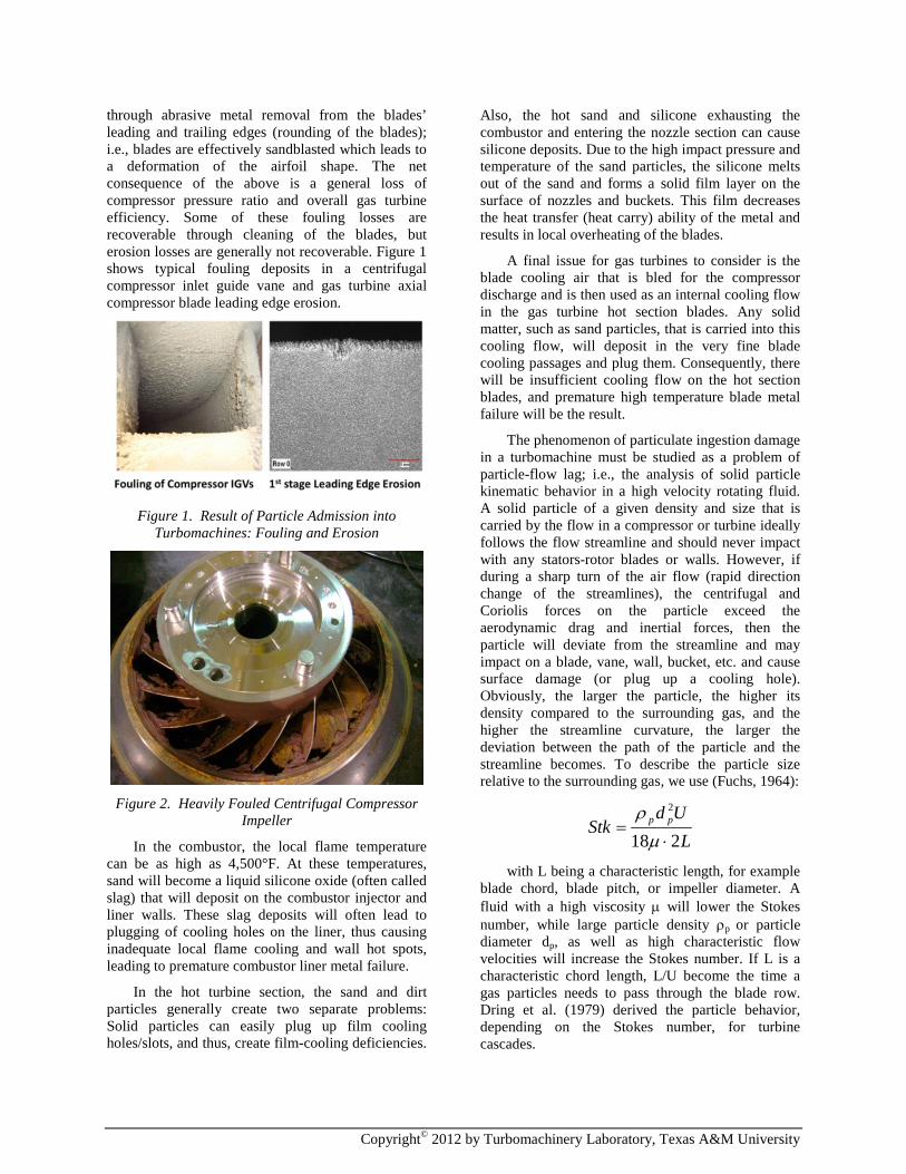
through abrasive metal removal from the blades’ leading and trailing edges (rounding of the blades); i.e., blades are effectively sandblasted which leads to a deformation of the airfoil shape. The net consequence of the above is a general loss of compressor pressure ratio and overall gas turbine efficiency. Some of these fouling losses are recoverable through cleaning of the blades, but erosion losses are generally not recoverable. Figure 1 shows typical fouling deposits in a centrifugal compressor inlet guide vane and gas turbine axial compressor blade leading edge erosion.
Figure 1. Result of Particle Admission into
Turbomachines: Fouling and Erosion
Figure 2. Heavily Fouled Centrifugal Compressor
Impeller
In the combustor, the local flame temperature can be as high as 4,500°F. At these temperatures, sand will become a liquid silicone oxide (often called slag) that will deposit on the combustor injector and liner walls. These slag deposits will often lead to plugging of cooling holes on the liner, thus causing inadequate local flame cooling and wall hot spots, leading to premature combustor liner metal failure.
In the hot turbine section, the sand and dirt particles generally create two separate problems: Solid particles can easily plug up film cooling holes/slots, and thus, create film-cooling deficiencies.
Also, the hot sand and silicone exhausting the combustor and entering the nozzle section can cause silicone deposits. Due to the high impact pressure and temperature of the sand particles, the silicone melts out of the sand and forms a solid film layer on the surface of nozzles and buckets. This film decreases the heat transfer (heat carry) ability of the metal and results in local overheating of the blades.
A final issue for gas turbines to consider is the blade cooling air that is bled for the compressor discharge and is then used as an internal cooling flow in the gas turbine hot section blades. Any solid matter, such as sand particles, that is carried into this cooling flow, will deposit in the very fine blade cooling passages and plug them. Consequently, there will be insufficient cooling flow on the hot section blades, and premature high temperature blade metal failure will be the result.
The phenomenon of particulate ingestion damage in a turbomachine must be studied as a problem of particle-flow lag; i.e., the analysis of solid particle kinematic behavior in a high velocity rotating fluid. A solid particle of a given density and size that is carried by the flow in a compressor or turbine ideally follows the flow streamline and should never impact with any stators-rotor blades or walls. However, if during a sharp turn of the air flow (rapid direction change of the streamlines), the centrifugal and Coriolis forces on the particle exceed the aerodynamic drag and inertial forces, then the particle will deviate from the streamline and may impact on a blade, vane, wall, bucket, etc. and cause surface damage (or plug up a cooling hole). Obviously, the larger the particle, the higher its density compared to the surrounding gas, and the higher the streamline curvature, the larger the deviation between the path of the particle and the streamline becomes. To describe the particle size relative to the surrounding gas, we use (Fuchs, 1964):
LUd
Stk pp
218
2
⋅=
µρ
with L being a characteristic length, for example
blade chord, blade pitch, or impeller diameter. A fluid with a high viscosity µ will lower the Stokes number, while large particle density ρp or particle diameter dp, as well as high characteristic flow velocities will increase the Stokes number. If L is a characteristic chord length, L/U become the time a gas particles needs to pass through the blade row. Dring et al. (1979) derived the particle behavior, depending on the Stokes number, for turbine cascades.

Copyright© 2012 by Turbomachinery Laboratory, Texas A&M University
For a given gas path geometry, the probable particle impact regions, forces, and likely surface damage can be evaluated using particle lag theory and computational fluid dynamics. Figure 3 schematically shows the Eulerian forces that affect the motion of a particle in a moving fluid.
Figure 3. Forces Acting on a Particle Transported
by a Fluid in Motion: Drag and Inertial
This paper describes a set of application tools that is based on a mix of CFD and a semi-empirical particle transport model to predict gas path solid particle erosion and fouling in most types of turbomachines. The model has been verified using actual high-speed turbomachinery sand testing and laser PIV on airfoil sections. The tool has already employed this particle lag analysis method to successfully predict the characteristic behavior and impact forces of solids in an axial air compressor for a refinery compression application.
The herein described turbomachinery particle flow analysis tool can be applied to any centrifugal, compressor, ground-based gas turbine, or aircraft jet engine, axial compressor, or any other turbomachine subjected to solid particle ingestion, to predict:
• The size and density of particles primarily responsible for damage, erosion, and degradation in the turbomachine. With this knowledge, the filter size and design can be optimized.
• The local impact force of sand particles on the turbomachine’s internal blades, vanes, nozzles, walls, etc. Using these results, the coating life, metal abrasion, and wear can be predicted to improve scheduling of the turbomachine’s maintenance intervals.
• The highest probability areas within gas path for fouling, deposit formation, and cooling flow interruptions; i.e., probable failure areas. Based on these results, the maintenance team
can focus on high-risk areas for closer and more frequent inspection.
The above analysis results allow one to develop a strategy to “harden” a machine’s gas path locally against the damaging effects of sand ingestion and/or to develop better maintenance techniques. For example, areas that have been identified to have the highest amount of particulate impacts and forces could be locally strengthened, or a surface coating could be applied for special protection. Also, analysis results showing that only certain size and weight particles ingested into the gas path are responsible for the majority of damage could lead to the improvement of filtering techniques to only target these particles rather than the currently employed total filtering method. Finally, by identifying the areas that suffer most particulate damage, inspection and replacement strategies can be implemented to reduce cost of downtime and repair. By proper implementation of the analysis results into a turbomachinery filtration, inspection, maintenance, and hardening optimization strategy, significant cost savings and increased equipment availability can be achieved.
Thus, the primary aim of the herein described project was to develop a software tool that would allow detailed analysis of the kinematic behavior of sand and other particulates inside a turbomachine such as a gas turbine, centrifugal, or axial flow compressor. Based on this tool’s output information, improved inlet air filtering techniques, engine maintenance, and component designs were realized. These improvements were based on real data rather than the current simple approach of crude inlet filtering, component over-design, and/or reactive internal part fixes to existing equipment.
In parallel with the analytical work of this project, particle injection into a full scale rotating impeller was tested on a high-speed rotating machinery test rig to verify the method and optimize the model’s implementation to reflect rotating machinery particle impact behavior more accurately. Thus, once the particle transport model had been fine-tuned, a generally applicable method was available to accurately predict the motion and impacting of sand and other impurities on the internal structures of the gas path of a turbomachine.
PROBLEM STATEMENT
The phenomenon of particulate ingestion damage in a turbomachine’s gas path can be studied as a problem of particle-flow transport (i.e., the analysis of solid particle kinematic behavior in a highly non-uniform and high velocity fluid flow). A solid

Copyright© 2012 by Turbomachinery Laboratory, Texas A&M University
particle of a given density and size that is carried by the flow through the gas path, ideally follows the flow streamline and should never impact with any stators/rotor blades or walls. However, if during a sharp turn of the flow (rapid direction change of the streamlines) or during a rapid transient flow fluctuation, the centrifugal, inertial, and Coriolis forces on the particle exceed the aerodynamic drag forces, then the particle will deviate from the streamline and may impact on a blade, vane, wall, bucket, etc. and cause surface damage (or plug up a cooling hole). For a given machine gas path geometry, the probable particle impact regions, forces, and likely surface damage can be evaluated using particle lag transport theory and CFD. Figure 4 schematically shows how a force imbalance on a particle can cause it to deviate from the streamline path and impact a surface.
Figure 4. Particles Deviating from Streamlines and
Impacting on Surfaces in the Blade Path
As the fluid flow in a turbomachine is highly non-uniform, particle lag due to non-linear fluid behavior becomes a major contributor to component degradation. Unfortunately, CFD and particle transport calculations are computationally intensive and sometimes numerically unstable. For example, the equation above is the kinematic equation of a motion for a single sphere in incompressible flow (at high Stokes numbers and low local Reynolds numbers) according to Maxey (1983). The solution of this equation requires conjugate CFD and particle transport analysis and is very complex.
The current state of the art thus is:
1. Numerical solutions to the Navier-Stokes equations can be obtained with a reasonable accuracy using modern, commercially available CFD codes.
2. These codes are intended to predict the fluid flow field only; they are generally not capable of solving transient particle transport kinematics problems.
3. Some commercial CFD codes offer particle transport modules and/or “tracer” visualization techniques, but these are essentially just visualization of the flow
streamlines or streak lines and do not predict how a multitude of particles would behave as they are carried by a highly unsteady flow: They are essentially only valid for very low Stokes number particles at low seeding densities.
4. More recently, a number of researchers have attempted to develop complex advanced transient CFD methods to predict solid particle transport behavior in turbomachines. These models are extremely computationally intensive and have not been fully validated. They usually do not account for particle interactions, particle bouncing off surfaces, and usually can only handle a single rotating stage.
Thus, a more efficient method must be utilized to determine probable particle impact locations and velocities. This method should still rely on CFD analysis of the steady flow field, but can utilize a simpler physical model to predict particle impact behavior. Within the subject project, a software tool was developed to accurately predict the behavior of solid particles, such as sand, dirt, and dust in a gas turbine engine, centrifugal, or axial compressor. The program’s analysis method was based on the
( ) ( ) ( ){ } ( ) ( )2 2110
( )( )
2 216
( )2 2 216 1/ 20( )
1 , 6 { ,2
/ { ( ) [ ( ), ] }} 6
[ ( )]
i ii iF F F i ii Y tY t
i it Y
Y t
Du d V t Y t t a V t Y t tidt Dt dt
d d V Y a ia a dri v t
dV ugm m m m m u a u
uuu
ρ ρ
τ
π µ
τ τ τπ µ
π τ
= − + − − − ∇ − −
Γ − − ∇ − ∇ − −
∫

Copyright© 2012 by Turbomachinery Laboratory, Texas A&M University
derivation of the particle transport kinematic mechanics in a high velocity fluid, the implementation of a numerical solution of these equations based on a given velocity vector and pressure/density scalar field, and the interfacing with commercially available CFD codes for prediction of and to overlay with the steady flow field. It was not within the project’s stated goals to develop a new CFD code, but rather to employ a proven commercial turbomachinery CFD code as a tool for predicting particle kinematics within the highly complex flow field of a gas turbine.
SOLUTION APPROACH
In summary, the problem statement is:
1. Various size/specific gravity solid particles can enter the machine’s gas path depending on the application.
2. The fluid flow in most turbomachines is highly non-uniform and unsteady due to stage-to-stage interactions.
3. If during a sharp turn of the airflow (rapid direction change of the streamlines) or during a rapid transient flow fluctuation, the centrifugal, inertial, and Coriolis forces on the particle exceed the aerodynamic drag forces, then the particle will deviate from the streamline and may impact a blade or wall.
4. The phenomenon of particulate ingestion damage in a turbomachine could be studied as a problem of particle-flow transport using conventional transient CFD solvers.
5. However, transient CFD and particle transport calculations are computationally intensive making them impractical to be used as a day-to-day engineering design or service tool.
The proposed approach for this project was thus to:
• Use conventional (commercially available) 3-D CFD to determine the steady state flow field in a single rotating stage without the influence of solid particles in the flow.
• Refine mesh only near critical gas path surfaces.
• Utilize the 3-D flow field near the surfaces to determine surface impact probabilities using simple non-dimensional coefficients of inertial versus drag forces on the particles.
This is based on the following assumptions:
Basic Assumptions • Particles of concern are larger than
Kolmogorov length scale and interact with fluid primarily through Stokes viscous drag.
• Inertial forces are linear acceleration/deceleration, centrifugal, and Coriolis.
• The surface near-field aerodynamics dominates the behavior of solid particles impacting blades/walls (at least on a probabilistic basis).
• Particle distribution is homogenous in space/time and Gaussian in size distribution.
• A steady state (rotating frame) CFD model and a stage-by-stage approach is adequate to determine particle impact locations. (Likely only valid for first few machinery stages)
Model Preposition • Determine the steady-state aerodynamic
flow field of the stage of a turbomachine and then utilize non-dimensional physical parameters related to solid particle lag to probabilistically predict impact locations.
Thus, to address this problem, the following tasks were implemented in parallel to achieving the project’s objectives.
Task 1 – Particle Transport Kinematics Analysis • Derivation of transient particle transport
equations and numerical model
• Implementation of the numerical model and CFD interface development
• Development of semi-empirical model to determine particle behavior
• Benchmarking of analysis method using simplified geometry
• Calibration of model based on experimental test data
• Application of code to first stage of centrifugal compressor (demonstration run)
Task 2 – Experimental Verification • Testing of particulate flow behavior in non-
rotating flow (PIV in wind tunnel)
• Benchmark testing of particulate flow behavior in rotating flow (high-speed compressor)
• Validation of CFD and semi-empirical model results using experimental results

Copyright© 2012 by Turbomachinery Laboratory, Texas A&M University
Test work in Task 2 required the utilization of flow visualization (PIV) and application of abrasive paints to determine impact behavior of particles. The analysis work in Task 1 was mostly completed utilizing a commercial CFD package, CFDesign by Blue Ridge Numerics.
LITERATURE REVIEW
Clearly, a number of researchers have investigated sand ingestion into turbomachinery. While fouling and erosion on axial turbomachinery are well publicized, there is not a large amount of literature on the deterioration of centrifugal gas compressors. Exceptions are the publications by Haq, et al. (1998) on the fouling on a process gas compressor. There are known issues with erosion on centrifugal compressors, including severe cases of almost complete removal of impeller vanes. In many applications, the ingestion of massive amounts of solids is not planned or anticipated, and often only detected after severe performance degradation of the compressor, or the occurrence of vibration issues. Similarly, submerged pumps have been evaluated for erosion due to solid particles (Hadiiyannis et al., 2009). In these machines, pumping incompressible fluid particles with higher diameter tends to increase the erosion rates inside the impeller, since they collide with greater forces to the impeller surfaces resulting also in higher erosion rates. On the other hand, where the flow velocity is decreased (i.e., diffuser) and the geometry of the flow path is instantly changing, the smaller particles are responsible for the higher erosion rates occurring in these critical areas of diffuser, since they tend to collide with higher impact velocities.
Solid particles may be transported into the gas turbine engine through the axial compressor as airborne ash particles, sand, other solid particulates, dust, and ice. The gas turbine combustor fuel system can also produce solid and molten particles when burning heavy oils or synthetic fuels. Particle transport paths and the effects of particle impact or deposition vary, based on the type and quality of material (synthetics vs. ash), size distribution, and the particle size, as well as the gas flow path, operating conditions, and the blade material, and geometry. Previous research has centered on the modeling, design mitigation, and prediction of namely four degradation and performance-related effects: 1) Compressor and turbine blade erosion; 2) deposition in the combustor and hot sections leading to corrosion; 3) impingement/deposition on GT blades leading to blockage of cooling passages, and 4) reduction of the efficiency and surge margin due to blade tip clearance reduction.
In the area of blade erosion and advanced surface coating development, wind tunnel tests of blade material and coating erosion are well documented by Hamed et al. (2006) - who has provided accounts of testing since 1960 over a range of temperatures, from ambient to 704°C with aluminum oxide, fly ash, quartz, sand, and chromite. Tabakoff et al. (1974) studied blade and coating erosion in an erosion wind tunnel to determine erosion rates and thermal barrier coating life reduction due to particle impact. Testing was performed over a range of typical hot section temperatures from 1,600 to 2,000°F to show the escalation of erosion rate due to increased temperature. Sand particle ingestion in particular was shown to blunt the leading edge of rotor blades, reduce blade chords, and increase surface roughness (Grant and Tabakoff, 1975). This experimental work indicated that larger particles will cause increased erosion rates, but the particle size dependency is reduced when the particle impact velocity decreases. Richardson et al. (1979) showed that the erosion effects on high pressure compressor blades tend to center on the outer 50% of the span, where notable reduction in blade chord length and thickness are significant. His work also showed the effect on airfoil surface roughness and a limit to the eroded surface roughness, whereby additional continued particle impacts and mass removal after 2,000 cycles proved to have no effect on the blade roughness.
Recent erosion test research has focused on the significant interaction and importance of the particle rebound condition, since the particle trajectories within the gas turbine engine are heavily affected by the rebound velocity and magnitude. Tabakoff and Sugiyama’s (1980) laser Doppler velocimetry measures (on fly-ash type particles) found that impact angle is the primary factor affecting the restitution ratio. Departures from the mean restitution ratio were notable for the non-rounded particles. Sand particle ingestion was studied by Cowan et al. (2010) through short pin fan array tests. The numerical simulations showed a dependency on the Stokes number of the particle. A smaller Stokes number particle size resulted in the highest deposition rate and least number of surface impacts (possibly due to a faster time to deposit and less resulting rebound impacts). The softening temperature was also shown to affect the deposition rate, whereby a lower softening temperature increased the number of deposits on the blades.
Regarding combustion/hot section deposition and related corrosion effects, it is important to consider the delivery of solid particles through the fuel system which may enter in solid and liquid form. Vaporization will likely occur in the hot section, but

Copyright© 2012 by Turbomachinery Laboratory, Texas A&M University
lead to deposition after condensation on cooler turbine surfaces in later stages of the turbine. The larger particles tend to collect due to inertial impact while smaller particles may be delivered by gas molecules at high temperatures. Extremely small particles may be transported by diffusion and also tend to collect on cooler surfaces (Hamed et al., 2006).
Dunn et al. (1996) investigated gas turbine operational effects when subjected to volcanic ash particles. This work showed images of the engine inlet characteristically known as “St. Elmo’s glow”, which appears due to the strikingly bright ring of light at the first rotor tip caused by dust particle ingestion. To cause material deposition in the hot section through thermally agitated gas particle transport of solids, Dunn reported the temperatures must be on the order of 2,000°F (1,094°C). Newer engines operating at these higher temperatures will experience both material deposition and erosion effects on the compressor and turbine blades.
In the area of deposition on the blades and blockage of cooling paths, considerable research has been done in predicting cooling hole blockage and design methods to counter this occurrence. Haase and Bons (2010) studied cooling hole deposition in the context of synthetic fuel usage. Flow visualization testing was performed to show that large deposits in the front rows of film cooling holes help to promote a cavity and coolant airflow, which is more stable than smaller depositions throughout the cooling holes. Walsh et al. (2006) studied sand ingestion on blockage of film cooling holes using a leading edge coupon over a range of sand particle size, amounts, and metal/coolant temperatures. Increased coolant velocity and pressure ratio were found to aid in passing particles through the coolant passage walls, causing less adherence to the surface. Metal temperature, however, was shown by Walsh to be the most significant parameter affecting particle adherence - temperatures of above 1,000°C were found to promote melting and blockage of cooling holes (a limit close to the one observed by Dunn).
Design investigations to aid in reducing cooling hole blockage are numerous. Land et al. (2010) investigated double-walled cooling geometries found that a staggered arrangement of film-cooling and impingement air flow holes could aid in breaking down larger particles. Musgrove et al. (2009) also designed and studied filtering of sand, resulting in a collector which developed an inlet vortex to create a favorable circulation pattern for particle collection.
Cardwell et al. (2009) focus in their study on a method that identifies the motion of foreign particles
within an internal ribbed passage such as they are used for internal cooling of blades and combustor liners. Their observations indicate significant bouncing of particles in the cooling passages, with the larger particles being more susceptible to bouncing. The bouncing phenomenon results from three conditions which are independent of the rib staggering: 1) a particle must impact the upstream rib face at a relatively high velocity; 2) the particle, having a sufficiently high Stokes number, follows a ballistic path across the channel while being accelerated by the carrier flow; 3) owing to the presence of ribs on the adjacent wall, the particle impacts another front rib face at sufficient velocity to restart the process.
The leading work in characterizing performance changes due to tip clearance reduction was performed by Dunn et al. (1996). They measured tip clearance reduction after erosion experiments using air entrained dust particles. The clearance reduction was reported to be greater than three times the initial tip clearance, which caused early surge in the machine, effectively eliminating the surge margin. Schmucker and Schaffer (1994) found that erosion lead to 1% loss in tip clearance corresponded to a 7.5% reduction in surge margin and a 2% loss in efficiency. Separately, A. Ghenaiet et al. (2005) focused a complete set of tests on sand ingestion in particular, using Lagrangian tracking methods for particles up to 1,000µm – and used the data to determine effects on adiabatic efficiency, pressure rise coefficient, and stall margin, with the blade chord reduction found to be a more dominant factor than the tip clearance loss. Relating turbomachine life to 10% efficiency drop, the authors showed that this efficiency drop occurred in less than 100 hours for sand particle concentrations of more than 100 mg/m3.
Apart from a study of how these degradation mechanisms occur or means of protecting against them, it is equally important to understand the behavior of solid particles with a reliable prediction of the particle transport path. Reliable particle transport prediction allows a designer/operator to understand if deposition or erosion is likely to occur based on particle residence time and particle locations. Hussein and Tabakoff (1973) provided the initial particle trajectory simulation effort in 1974, using experimentally obtained restitution ratios to simulate various particle trajectories. The work showed that the blade surface impacts tend to increase with increasing particle diameter and increased velocities at the axial compressor stage inlet. Since this early research, three-dimensional flow effects and viscous forces have been incorporated into many Eulerian-Lagrangian models

Copyright© 2012 by Turbomachinery Laboratory, Texas A&M University
of particles in the flow stream. A more complete summary of work in radial inflow turbines and axial compressors is provided by Hamed et al. (2006).
Prediction of Motion of Particles in a Fluid The set of equations that govern the highly three-
dimensionally complex, transient, and rotating frame fluid flow in a turbomachine are known as the Navier-Stokes equations. Like all Newtonian conservation-based equations, they consist of a mass continuity, force balance, and energy balance equations. They are a set of higher order, coupled, nonlinear, and non-homogenous partial differential equations for which a closed form analytical solution can only be obtained for a limited set of very basic problems.
Numerical solutions to the Navier-Stokes equations can be obtained with a reasonable accuracy using modern, commercially available CFD codes. However, as these codes are intended to predict the fluid flow field only, they are generally not capable of solving transient particle transport kinematics problems. Some CFD codes offer simple single particle transport modules and/or “tracer” visualization techniques, but these are essentially just visualization of the flow streamlines or streak lines and do not predict how a multitude of particles would behave as they are carried by a highly unsteady flow.
Thus, to analyze particle movements within an unsteady fluid flow, it is first necessary to determine the transient flow field (using CFD codes) and then apply time-dependent particle transport equations to model individual particle kinematics within the three-dimensional flow field. As the analysis has to be performed in a complex three-dimensional flow field with very small transient time steps to capture a highly unsteady flow field, the solution is numerically intensive and difficult. Furthermore, there is very little experimental data available in the public domain that would allow one to compare analysis results with proven test data. To verify and calibrate a particle transport model, it is critically necessary to perform a number of laboratory tests on an actual high-speed rotating turbomachine, such as a centrifugal or axial compressor.
Proposed Analysis Approach Within the subject project, a CFD and semi-
empirical approach was utilized to determine particle behavior in turbomachines. This approach is based on using CFD to determine the steady-state flow field without the influence of particles and then to utilize the 3D flow field results to determine surface impact velocities using a semi-physical model. Namely, once a flow field for a rotating machine was determined
using a commercial CFD solver, the following approach was taken:
The motion of a particle can be determined based on a simple model that balances inertial (centrifugal, Coriolis) and drag forces on the particle. Namely, a model based on:
with some determinable velocity vector impact coefficients, appears to adequately predict the motion of particles around a stationary airfoil. Non-dimensional (Buckingham-Pi) analysis shows that the velocity and direction of a particle near an airfoil must follow the functional forms shown in Table 1:
Table 1: Non-dimensional parameters governing the particle behavior in unsteady flow
These non-dimensional numbers are solely
related to particle lag (inertial) forces acceleration/deceleration, centrifugal, and Coriolis forces. The denominator is either viscous fluid force or drag force on the particle. The numerator is inertial forces. Viscous/drag forces carry particle on streamline. Inertial forces cause particle to deviate from streamline. Intuitively, we can say that:
• If γ and Г are small, particles follow streamline
• If γ and Г are large, particles deviate from streamlines
With this understanding, one can form the following hypothesis: The ability of a solid particle to follow a streamline vector V is related to the non-dimensional parameters and some undefined Velocity Vector Impact (VVI) coefficients: A, B, C, D, E, and F based on the following functional form for the particle’s velocity vector:
where V is a normalized velocity vector in the near-field (in the boundary layer) of a surface in the flow. VVIs A, B, and C correspond better to laminar (viscous forces) dominated flow while D, E, and F,
DragCoriolislCentrifuga FFFdtVdm
=++
OCIOCI FEDCBAV Γ+Γ+Γ+++= γγγ

Copyright© 2012 by Turbomachinery Laboratory, Texas A&M University
correspond to turbulence (high Re) dominated flow. The coefficients are somewhat redundant, but since the flow in gas turbines is highly turbulent, it is easier to use the turbulence VVIs (D, E, F).
As an aside, the commonly used Stokes number is defined as:
𝑆𝑡𝑘 =𝑃𝑎𝑟𝑡𝑖𝑐𝑙𝑒 𝑆𝑡𝑜𝑝𝑝𝑖𝑛𝑔 𝐷𝑖𝑠𝑡𝑎𝑛𝑐𝑒𝐶ℎ𝑎𝑟𝑎𝑐𝑡𝑒𝑟𝑖𝑠𝑡𝑖𝑐 𝐿𝑒𝑛𝑔𝑡ℎ
= 𝜏 ∙ 𝑈𝐿
Such that for Stk<<1 particles follow streamline and for Stk>>1 particle deviate from streamline. Here, τ is indirectly derived from measurement or analysis. Stk and τ are not easy to use, as it does not directly relate to flow field or force parameters that could be obtained from CFD. Other Stokes number equations have been derived for specific applications, e.g., Booker (1998) proposed for aerosol transport in curved ducts:
𝑆𝑡𝑘 =𝑅2 ∙ 𝜌 ∙ 𝑉
𝜇𝑟
which is similar to the above described γI term.
The analysis approach is schematized in Figure 5.
Figure 5. Functional Description of Particle Vector
with D, E, F VVIs
Based on the above, the individual VVIs (D, E, F) must be determined for each direction (radial, tangential, and normal) individually from the steady state CFD analysis. Relative to the stationary frame, these approximately correspond to the centrifugal, acceleration/deceleration, and Coriolis forces, respectively, but to accurately determine the VVIs, a detailed coordinate transformation must be performed. The only three coefficients that are required are, thus:
The analysis approach is:
• Calculate VVI coefficients (D, E, F) for each direction individually:
– D for ΓI (VVI acceleration)
– E for ΓC (VVI centrifugal)
– F for ΓO (VVI Coriolis)
• Calculated values of D, E, F near surface provide indication (likelihood) if particles will impact on wall/blade surface.
• To determine the impact velocity, it is assumed that the particle velocity will correspond to the average flow velocity just stream wise upstream from the surface boundary layer.
For small values of D, E, and F, particles are expected to deviate from streamline path and impact blade/wall. The sequential steps are:
For a given stationary or rotating flow path geometry:
1. Calculate the 3-D flow field around a given rotating or stationary geometry using CFD.
2. Determine the aerodynamic flow field near surfaces, and normalize flow vectors using the mean passage flow.
3. Determine non-dimensional coefficients, ΓI ΓO ΓC, corresponding to acceleration, Coriolis, and centrifugal forces divided by drag force.
4. Calculate VVI coefficients D, E, F for each flow direction.
5. Overlay results of D, E, and F as a surface contour on blade/wall geometry to identify the regions of highest probability of particle impacts.
6. Small values of D, E, and F (less than unity) indicate that the non-drag forces dominate on the particles will likely impact.
7. For the highest probability regions (VVI < 0.5), the impact velocities are then calculated from CFD results using local velocity vectors stream wise upstream of the impact locations.
The impact density of the particles behaves linearly with the VVI coefficients. One should note

Copyright© 2012 by Turbomachinery Laboratory, Texas A&M University
that the impact velocity is a vector and that the non-dimensional coefficients must consequently be individually evaluated for each direction (x, y, z in the stationary frame; the normal, bi-normal, and tangential directions relative to the moving blade in the rotating frame). Also, because of the linearized equation form assumption, the velocity vector V and VVIs will be valid only for the immediate vicinity around a blade, impeller, vane, or airfoil (which is the primary region of interest of this project).
To determine the impact velocity, it was assumed that the particle velocity will correspond to the average flow velocity just stream wise upstream from the particle location. Although this assumption is likely to be somewhat conservative (i.e., impact velocities will be over predicted), to meet the objective of this project, this approach is generally preferred.
PARTICLE ANALYSIS IN NON-ROTATING FLOW
Prior to performing experimental and CFD work on particulate behavior in the rotating frame, a set of experiments to verify the approach in the stationary frame was undertaken. The geometry for analysis selected was NACA-0009 airfoil, which is a blade shape commonly utilized in the gas turbine industry for stationary flow elements. Sand behavior around the blade was analyzed using both CFD and experimental flow visualization.
Case Study 1: Sand Impacting Blade in Non-Rotational Flow Field
To analyze how various sizes and specific density sands behaved around a NACA-0009 airfoil, an airfoil was mounted in a small wind tunnel, and a simple (PIV) system was devised. The PIV system consisted of a 300 mW Argon-Ion laser, a mirror mounted on a small high-speed DC motor, and a 35 mm camera. In this simple arrangement, the laser beam is aimed at the rotating mirror (rotating at 11,000 rpm) to generate a light sheet in the wind tunnel. Particles such as sand grains, flowing through the wind tunnel, will scatter light as they cross the light sheet. A slow exposure photograph of this light scatter allows one to trace the movement of single particles at fixed intervals corresponding to the rotational speed of the laser beam in the light sheet. Thus, velocity vectors for a 2-D section of the entire flow field can quickly be determined.
For the analysis of sand flow over a NACA-0009 airfoil, three different sand grain sizes, three angles of attack, and two airflow velocities were tested. Velocity vectors were then compared to a CFD analysis of the same airflow.
Results of Particle Behavior in Stationary Frame Sand kinematic behavior was studied around
NACA-0009 airfoils for various flow incidence angles. This study was performed to evaluate the relative influence of streamline curvature and particle size on the motion of particles in the airflow, as well as to test some basic particle kinematic theories. For this task, a small wind tunnel was constructed and a 300 mW Argon-Ion laser was employed to visualize particles carried by the flow using a basic PIV technique. The wind-tunnel utilized an open loop centrifugal air compressor discharge and was capable to produce test section flows up to Mach=.95. The wind-tunnel also included an optical window and upstream particle seeder. Figure 6 shows the wind-tunnel test section optical window.
Figure 6. Wind-tunnel Optical Window
Figure 7. Typical PIV Results for Stationary Frame
Measurements
Three sand grain sizes were tested:
• Coarse: 0.5 mm average particle size
• Medium: 0.2 mm average particle size
• Fine: 0.05 mm average particle size
At three different flow incidence angles of attack (0, 5, and 10 degrees) all three sands had approximately equal specific gravities of approximately 2.1. In summary, the non-rotating flow experiments included:
• NACA-0009 airfoil test article mounted in small subsonic wind-tunnel
• A simple PIV system was devised. The PIV system consisted of a 300 mW Argon-Ion

Copyright© 2012 by Turbomachinery Laboratory, Texas A&M University
laser, a mirror mounted on a 20,000 rpm high-speed DC motor, and a 35 mm camera.
• A slow exposure photograph of this light scatter allows one to trace the movement of single particles at fixed intervals corresponding to the rotational speed of the laser beam in the light sheet.
• Velocity vectors for a 2-D section were determined from slow exposure photograph
• Three different sand grain sizes, three angles of attack, and two airflow velocities were tested.
• Velocity vectors were then compared to a VVI analysis based on CFD of the same airflow.
Experimental results showed that smaller particles tend to follow the flow streamlines more closely than larger particles. CFD Comparison
In parallel to the experimental work, a simple 2-D CFD model was employed to determine the transient streamlines (velocity and local curvature) of the flow around the airfoil (see Figure 8).
Figure 8. CFD Model of NACA-0009 Airfoil Flow
Based on the CFD results, the above described VVI coefficients were determined. Typical results are shown in Table 2 and Figure 9 for the 0.2 mm particle sand. Impact locations and impact velocity results were consistent (within 20%) with PIV observations.
Table 2: 0.2 mm Sand on NACA 009 Airfoil at Aero Incidence Flow
Figure 9. VVI Total Sum Indicating Probability of
Particle Impacts on Leading Edge of Airfoil
Comparison of the results in Table 2 with the PIV measurements showed that the highest impact blade impact velocities and probability of impact were at the leading edge. These results were consistent with PIV observations and experimental results in the public domain. One should note that the F-VVI term was zero for all cases. This term corresponds to Coriolis forces, which are not acting in a non-rotating flow field.
PARTICLE ANALYSIS IN ROTATING FLOW
Case Study 2: Sand Ingestion into a Centrifugal Compressor
When expanding the previous model to the rotating frame, particular care has to be given to the inertial terms, as the particles in the fluid will also be affected by global centrifugal and Coriolis forces. To develop this model for the rotating frame, experimental sand injection work has been performed in a high-speed compressor at SwRI. CFD results can then be correlated to the experimental results with the aim of determining the VVI coefficients as a generalized model for sand transport near airfoils in a high-speed turbomachine.
Figure 10. Single-stage Impeller CFD Model

Copyright© 2012 by Turbomachinery Laboratory, Texas A&M University
CFD Modeling Approach CFD work was performed to provide a baseline
for experimental results. A high-speed centrifugal compressor onsite at SwRI was modeled using a 3-D solid modeling package. Only one stage of the two-stage compressor was modeled, as this single impeller is the focus of experimental work (see Figure 10).
This geometric representation was then imported into a commercial CFD code. Using expected experimental parameters, a series of CFD simulations were conducted to determine flow field characteristics at the leading edges of the impeller blades. The velocity components were taken from the CFD analysis to compute the non-dimensional flow and VVI parameters previously defined in this project summary.
Figure 11. CFD Results – Velocity Magnitude Plat
and Vector Plot near Leading
A series of models have been analyzed using various permutations of mesh density, boundary conditions, and turbulent flow models. The data presented here is from a simulation that is largely representative of all the runs performed. The captures below (Figure 11) depict CFD output of flow velocity inside the impeller gas volume.
It should be noted that the images represent geometry of the fluid volumes and not the solid components of the compressor. The software package being used for this analysis allows for flow characteristics to be determined at specific locations. One area of particular interest being studied is the leading edge of the impeller blades. The velocity vector plot shows the behavior of the flow in this area.
The non-dimensional parameters previously discussed in this report were calculated based on the CFD results. For properties of sand, desert sand from Qatar was ascertained and analyzed. Average density and radius values were used for all calculations. This CFD analysis was repeated for a number of flow and head conditions of the compressor as shown in Table 3:
Table 3: Flow and head conditions for centrifugal compressor particle ingestion tests
Case Speed [rpm]
Flow [acfm]
Pressure Ratio
1 5,000 8,000 1.05
2 5,000 7,000 1.15
3 10,000 16,000 1.05
4 10,000 14,000 1.15
Some parametric studies of the CFD analysis were also performed to develop a qualitative understanding of the relative physical influences of each of the VVI coefficients. For example, computations demonstrated that the simple inertial terms were dominated by centrifugal and Coriolis terms. While the centrifugal parameters did not vary significantly at small distances from the leading edge of the impeller blades, the Coriolis parameters showed significant dependence of position. Figure 12 is a representative plot showing the Coriolis terms as a function of radial distance from leading edge of a rotating compressor blade.

Copyright© 2012 by Turbomachinery Laboratory, Texas A&M University
Figure 12. Coriolis VVI Terms as Function of Radial
Distance from Leading Edge
Testing of Particles in Compressor Experiments were performed using SwRI’s high-
speed centrifugal compressor test stand. A variable speed drive electric motor was used to drive the centrifugal compressor at speeds up to 10,000 rpm, and sand was injected into suction of the compressor. The test stand consists of a 700 hp EMD, driving a Clark 2-stage compressor through a gearbox capable of variable speeds up to 14,000 rpm which can be run in open or closed loop mode. Figure 13 shows the experimental compressor test stand used for the experiments.
Figure 13. Centrifugal Compressor Test Stand
The experiments were used to determine where sand impacted the impeller blades. Only one stage of the compressor was used for this analysis. The surfaces of the impeller exposed to airflow were painted with an abradable paint prior to each test run. The impeller was inspected after each test run to determine where sand impacted the blades.
Measured quantities of sand and other particles were injected into the suction flange of the compressor upstream of the impeller and mixed using a pre-swirler. As the compressor was operated in an open-loop arrangement, the sand particulates passed
only once through the compressor before being discarded. This allowed also for easy control and consistency of the quantity of sand passed through the compressor for each test. After all particles had passed through the impeller, the hardware was disassembled and visually inspected for paint abrasion. From the visual inspection, the main particle impact locations were measured, and the impact density was inferred. Figure 14 shows leading edge abrasion of paint at on the compressor impeller inlet.
Figure 14. Visual Inspection of Leading Edge of the
Impeller Blades after Fine Sand Ingestion
Three separate test runs were performed. The first used sand (ρ = 1.694 g/mL) with a compressor speed of 10,000 rpm. The second test used diatomaceous earth (ρ = 0.325 g/mL), and the third test again used sand. These last two experiments were run with the compressor operating at 5,000 rpm. In summary, the testing performed included:
• Experiments were performed using SwRI’s low pressure centrifugal compressor in open loop configuration with a Clark 2-Stage compressor driven through gearbox by EMD up to 14,000 rpm
• Surfaces of the impeller exposed to airflow were painted with an abradable paint prior to each test run.
• Measured quantities of solids (sand) were gradually injected into suction flange.
• After the test, the machine was disassembled and visually inspected for abrasion.
• Main particle impact (paint erosion) locations were measured, and the impact density was inferred (visually).
0 0.1 0.2 0.3 0.4 0.5 0.6 0.7 0.8
Distance from Leading Edge (mm)
Scal
ed N
on-D
imen
sion
al P
aram
eter
(Cor
iolis
/Dra
g)Re < 100Re > 100

Copyright© 2012 by Turbomachinery Laboratory, Texas A&M University
Test runs performed:
1. Fine Sand (D=0.05 mm, ρ = 1.694 g/mL) at 10,000 rpm
2. Fine Sand (D=0.05 mm, ρ = 1.694 g/mL) at 5,000 rpm
3. Diatomaceous Earth (D=0.002 mm, ρ = 0.325 g/mL) at 5,000 rpm
Experimental Results Analysis of the experimental results allowed the
comparison of predicted VVI coefficients from the CFD results with actual particle impact distribution of inside a high-speed centrifugal compressor (or any other turbomachine). For each test, all abrasion locations inside the impeller were documented by their location, size, and relative paint removal (visual only). These locations and sizes were then directly compared to a map of the sum of VVI coefficients and individual VVI direction coefficients for each directional component determined from the CFD results.
The map and the photograph could then be overlapped to determine whether the CFD code reasonably well predicted the highest probability impact locations of sand for a given grain size and operating conditions. Figure 15 shows the VVI map and the photograph are overlapped to determine whether the CFD code reasonably well predicted the highest probability (inverse VVIs) impact locations of fine sand for a given grain size and operating conditions. Good agreement between VVI coefficients and local abrasion is seen in this figure. Fine sand showed significant erosion of the abradable paint in the flow path. Diatomaceous earth caused negligible surface erosion but resulted in fouling.
Figure 15. Sand Abrasion in Centrifugal Impeller
with Local VVI Coefficients
A similar analysis was performed for all test results for the impeller sand ingestion testing. For each location that was identified in the test to show
significant sand abrasion, the CFD analysis results were overlapped and compared.
Results of Rotating Frame Analysis Generally, good agreement was found between
the predicted highest probability impact locations (from the VVI coefficients) and the actually observed test results for all operating conditions of the compressor. It is difficult to define an absolute uncertainty of this type of measurement, as the inspections are performed visually, and the comparison is somewhat qualitative in nature. However, results showed that whenever any of the individual VVI coefficients normal to the surface were below 0.5, or the sum of the VVI coefficients normal to the surface (in the rotating frame) were 0.8, then a measurable area of particle impacts was identified in all test cases. Thus, if the model predicts an area where sand will impact, then there is a very high probability of actual sand abrasion.
Nonetheless, for a number of cases, it was determined that the VVI coefficients underpredicted particle impact locations (i.e., particle impact locations that were experimentally observed were not properly predicted). This corresponded to approximately 20% of all particle impact locations (i.e., the model has a miss rate of approximately 20%). This incomplete prediction capability is likely due to the uneven flow particle stream of the sand that was entrained into the centrifugal impeller geometry. In real life turbomachinery applications, it is likely that the model would miss a smaller number of impact locations than the laboratory tested and have an improved miss rate of approximately 10%. Another issue might be the effect of particles bouncing off the airfoils (Beacher et al., 1982).
The rotating frame analysis did not allow for a direct determination of impact velocities from the testing results (as did the PIV), but the impact density from the test results provided some indication of the strengths of relative impacts of the particles. Qualitatively good agreement was found.
SUMMARY AND CONCLUSIONS
Commercially available CFD was combined with a semi-physical (or semi-empirical) model to predict the behavior of solid particles, such as sand, dirt, and dust, in turbomachines, such as centrifugal compressors, gas turbine engines, or axial compressors. The approach is based on using CFD to determine the flow field without the influence of particles, and then to utilize the steady 3D velocity flow field results to determine probable particle impact locations and surface impact velocities, using a non-dimensional influence coefficients.

Copyright© 2012 by Turbomachinery Laboratory, Texas A&M University
Specifically, the analysis method was based on the derivation of the particle transport non-dimensional parameters in a rotating, high velocity fluid and the implementation of a numerical solution of these equations based on a given velocity vector field, determined through interfacing with the commercially-available CFD codes.
1. The experimental test and CFD/semi-empirical model agreement showed good agreement in a qualitative sense and demonstrated that this approach can be used to predict impact location to better design against erosion and fouling losses within the turbomachine. This approach provides a simple method for predicting likely solid particle impact locations without the need for complex transient particle transport CFD calculations.
2. Comparative tests of sand flow in a wind tunnel around a NACA-0009 airfoil and sand flow inside a high-speed centrifugal compressor showed good agreement of the CFD and semi-empirical model predictions. The model properly predicted likely particle impact locations with a miss rate of approximately 20%. This miss rate is likely due to effects related to the laboratory testing and would be smaller in real applications.
3. The above analysis results allow one to develop a strategy to “harden” a turbomachine locally against the damaging effects of sand or dirt ingestion and/or to develop improved maintenance techniques. For example, areas that have been identified to have the highest amount of particulate impacts and forces can be locally strengthened or a surface coating can be applied for special protection. By identifying the areas that suffer most particulate damage, pro-active inspection and replacement strategies can be implemented to reduce cost of downtime and repair.
NOMENCLATURE
A, B, C, D, E, F Velocity Vector Impact Coefficients L Characteristic Length in Stokes Number R Mean Radius of Particle Stk Stokes Number U Absolute Velocity in Stokes Number V Velocity Vector a Particle Acceleration f Particle Force m Particle Mass r Radius of Curvature of Streamline t time
v Velocity Component Γ Non Dimensional Coefficient for Particle Behavior (Turbulent) γ Non Dimensional Coefficient for Particle Behavior (Laminar) μ Viscosity ρ Density τ Particle Stopping Time in Stokes Number Subscripts: C Centrifugal f Flow I Inertial Mass Acceleration O Coriolis p Particle r radial t tangential
REFERENCES
Beacher, B, Tabakov, W., Hamid, A., 1982, “Improved Particle Trajectory Calculations through Turbomachinery Affected by Ash Particles,” ASME JEng for Power, Vol. 104, pp. 64-68.
Bec, J., Cencini, M., Hillerbrand, R., 2006, “Heavy particles in incompressible flows: The Large Stokes Number Asympototics,” Physica D: Nonliner Phenomenon, Vol. 226, Issue 1, pp. 11-22.
Booker, D.R., 1998, “Aerosol Sampling Guideline,” Cambridge Press, London.
Brun, K. and Kurz, R., 1999, “Gas Turbine Theory,” Textbook published by Solar Turbines in three editions, ISBN 0-615-11751-1.
Cardwell N. C., Vlachos, P. P., Thole, K. A., 2009, “A Method for Identifying and Visualizing Foreign Particle Motion Using Time Resolved Particle Tracking Velocimetry,” ASME Paper GT2009-60273.
Cowan, J. B., Tafti, D. K., and Kohli, A., 2010, “Investigation of Sand Particle Deposition and Erosion within a Short Pin Fin Array,” ASME Paper No. GT2010-22362, Proceedings of the ASME Turbo Expo, Glasgow, UK.
Dring, R. P., Caspar, J. R., Suo, M., 1979, “Particle Trajectories in Turbine Cascades,” AIAA J Energy, Vol. 3, No. 3, 794102
Dunn, M. G., Baran, A. J., and Miatech, J., 1996, “Operation of Gas Turbine Engines in Volcanic Ash Clouds,” Journal of Engineering for Gas Turbines and Power, Vol. 118, pp. 724-731.

Copyright© 2012 by Turbomachinery Laboratory, Texas A&M University
Fuchs, N. A., 1964, “The Mechanics of Aerosols,” Pergammon, Oxford, UK.
Ghenaiet, A., Tan, S. C., and Elder, R. L., 2005, “Prediction of an Axial Turbomachine Performance Degradation due to Sand Ingestion,” Proc. IMechE, Vol. 219, Part A., J. Power and Energy, pp. 273-287.
Grant, G. and Tabakoff, W., 1975, “Erosion Prediction in Turbomachinery Resulting from Environmental Particles,” Journal of Aircraft, Vol. 12. No. 5, pp. 471-478.
Haase, K. and Bons, J. P., 2010, “Velocity Measurements around Film Cooling Holes with Deposition,” ASME Paper No. GT2010-22358, Proceedings of ASME Turbo, Glasgow, UK.
Hadiiyannis, S., Charalambous, N.,Tourlidakis, A., Michaelides, K, 2009, “An Experimental and Computational Study of the Erosion in Submersible Pumps and the Development of a Methodology for Selecting Appropriate Protective Coatings,”ASME Paper GT2009-60090.
Hamed, A., Tabakoff, W., and Wenglarz, R., 2006, “Erosion and Deposition in Turbomachinery,” Journal of Propulsion and Power, Vol. 22, No. 2, pp. 350-360.
Haq, I. U., Bu-Hazza, A. L., Al-Baz, K., 1998;”Multistage Centrifugal Compressor Fouling Evaluation at High Power Settings”, ASME paper 98-GT-53.
Hussein, M. F., and Tabakoff, W., 1973, “Dynamic Behavior of Solid Particles Suspended by Polluted Flow in a Turbine Stage,” Journal of Aircraft, pp. 434-440.
Jeske, H. O., Sandstede, H., 1985, “Turbine Blade Behaviour [sic] in Gas Streams Containing High Dust Loads,” Forschung im Ingenieurwesen Vol. 51, Nr. 2, pp. 52 –62
Kurz, R., Brun, K., 2009, “Gas Turbine Tutorial: Maintenance and Operating Practices Effects on Degradation and Life,” Turbomachinery Symposium, Houston, Texas.
Land, C. C., Joe, C., and Thole, K. A., 2010, “Considerations of a Double-Wall Cooling Design to Reduce Sand Blockage,” Journal of Turbomachinery, Vo. 132/031011-1.
Lawson, F. A. Thole, K., 2010, “Simulations of Multi-Phase Particle Deposition on Endwall Film-Cooling,” ASME Paper GT2010-22376.
Maxey, M. R., 1983, “Equation of Motion for a Small Rigid Sphere in Non-uniform Flow,” Journal of Physics of Fluids, Vol. 26, Issue 4, pp. 883-889.
Musgrove, G. O., Barringer, M. D., Thole, K. A., Grover, E., and Barker J., 2009, “Computational Design of a Louver Particle Separator for Gas Turbine Engines,” ASME Paper No. GT2009-60199, Proceedings of ASME Turbo Exp, Orlando, Florida.
Omid Gohardani, Impact of erosion testing aspects on current and future flight conditions, Progress in Aerospace Sciences, Volume 47, Issue 4, May 2011, Pages 280-303, ISSN 0376-0421, DOI: 10.1016/j.paerosci.2011.04.001. (www.sciencedirect.com/science/article/pii/S0376042111000315).
Richardson, J. H., Sallee, G. P., and Smakula, F. K., 1979, “Causes of High Pressure Compressor Deterioration in Service,” Proceedings of AIAA/SAE/ASME Joint Propulsion Conference, Las Vegas, Nevada.
Schmucker, J., and Schaffler A., 1994, “Performance Deterioration of Axial Compressors due to Blade Defects,” Propulsion and Energetic Panel, Symposium, Rotterdam, the Netherlands, April 25-28, 1994.
Simonis, J. C., et al., 2004 “The Silent Enemy: Effects of Sand and Fine Debris from Iraq and Afghanistan on Army Aviation Assets,” 6th International Filtration Conference.
Tabakoff, W., Grant, G., and Ball, R., 1974, “An Experimental Investigation of Certain Aerodynamic Effects on Erosion,” AIAA Paper 74-639.
Tabakoff, W., and Sugiyama, Y., 1980, “Experimental Methods of Determining Particle Restitution Coefficients.”
Walsh, W. S., Thole, K. A., and Joe, C., 2006, “Effects of Sand Ingestion on the Blockage of Film-Cooling Holes,” ASME Paper No. GT2006-90067, Proceedings of ASME Turbo Expo, Barcelona, Spain.
Wilcox, M., Brun, K., Kurz, R., 2011, “Successful Selection and Operation of Gas Turbine Inlet Filtration Systems,” Turbomachinery Symposium, Houston, Texas.