analysis of powder compression molding for …onlinepresent.org/proceedings/vol140_2016/40.pdf ·...
TRANSCRIPT

Analysis of Powder Compression Molding for
Automotive Components Using Finite Element Method
Bum Suk Oh1, Ju Gwang Jang2, Key Sun Kim3*
1 Div, of Mechanical & Automotive Engineering, Kongju National University, 331717
Cheoan, Korea 2 Div, of Mechanical & Automotive Engineering of Kongju National University, 331717
Cheoan, Korea 3* Div, of Mechanical & Automotive Engineering, Kongju National University, 331717
Cheoan, Korea
Abstract. The present study was conducted concerning powder compression
molding of automotive components, with the purpose of obtaining optimum
conditions through numerical simulation of changes in relative density
distribution produced upon powder compression as a function of change in
friction forces between the mold and the material by using FEM. By varying
friction coefficients, 4 cases of the variable were considered, and a total of 2
stages of compression process were implemented starting with the initial
density. As a result, a uniform relative density distribution could be observed
when the coefficient of friction was (c).
Keywords: Sintering, Density distribution, Powder Metallurgy.
1 Introduction
In general, powder metallurgy method is one of the widely employed methods as a
manufacturing technique for contemporary metal and ceramic products, and involves
pressure molding of powder, followed by sintering at high temperatures to obtain final
products.[1] Advantages of the powder metallurgy method include reduction in
processing unit cost by omission of machining processes and ability to mix diversified
materials. However, the method has a disadvantage of being difficult to obtain
uniform density distribution in the product due to the process characteristics. When
deviations in density distribution are large, distortion occurs upon sintering.[2]
Since obtaining uniform density in powder compression process is an important
item to remove distortion which can occur during sintering process, it is an item
which must always be considered. Thus, numerical simulation for distribution of
strength or density in powder compression process by using FEM(Finite Element
Method) can be an effective method.[3,4]
3* Key Sun Kim is the corresponding author
Advanced Science and Technology Letters Vol.140 (GST 2016), pp.207-210
http://dx.doi.org/10.14257/astl.2016.140.40
ISSN: 2287-1233 ASTL Copyright © 2016 SERSC

In the present study, distortion characteristics in the density disribution as a
function of friction coefficients was considered to obtain uniform density distribution
for automotive components. To quantitatively analyze the effects of friction
coeffecient between the mold and the material on distortion characteristics of density
distribution, analysis by FEM has been utilized, which was implemented in 3-
dimension by using a commercial dedicated software of DEFORM-3D.[5,6]
2 Method
2.1 Modeling and Materials
Fig.1 shows modeling for upper punch, lower punch, mold die, and automotive
component. Material used in the present study is 0.08%C carbon steel, chemical
composition data of which is given in Table 1. And the mechanical properties
summarized in Table 2.
Fig. 1. Modeling
Table. 1. Chemical composition of the metal powder
C (%) Si (%) Mn (%) P (%) S (%)
0.08 0~0.1 0.5~0.8 0~0.04 0.08~0.13
Table. 2. Mechanical properties of the material
Ultimate Tensile
Strength
Yield Tensile
Strength
Elongation
(in 50mm)
Young’s
Modulus Poisson’s Ratio
385MPa 325MPa 20% 205GPa 0.29
Advanced Science and Technology Letters Vol.140 (GST 2016)
208 Copyright © 2016 SERSC
2.2 Boundary Condition and Analysis Method
In the present study, meshing for FEM involved division into tetrahedron meshes.
And friction coefficients between the mold and the powder material were varied for a
total of 4 cases to conduct the analysis.
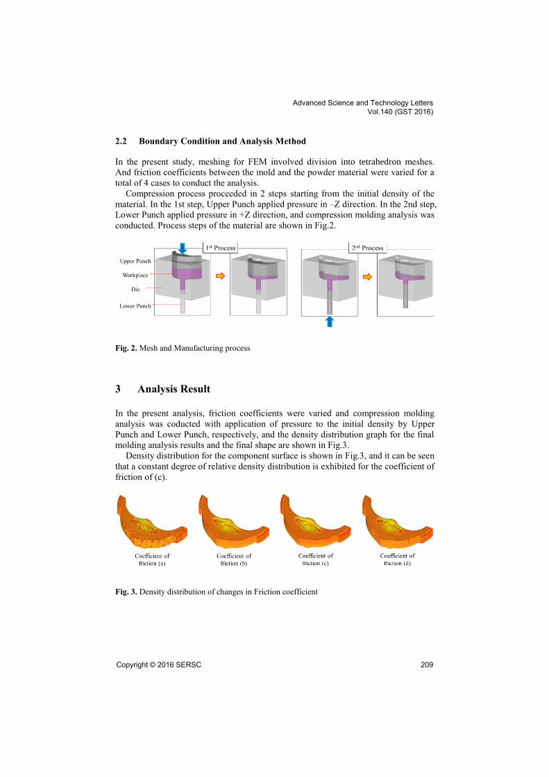
Compression process proceeded in 2 steps starting from the initial density of the
material. In the 1st step, Upper Punch applied pressure in –Z direction. In the 2nd step,
Lower Punch applied pressure in +Z direction, and compression molding analysis was
conducted. Process steps of the material are shown in Fig.2.
Fig. 2. Mesh and Manufacturing process
3 Analysis Result
In the present analysis, friction coefficients were varied and compression molding
analysis was coducted with application of pressure to the initial density by Upper
Punch and Lower Punch, respectively, and the density distribution graph for the final
molding analysis results and the final shape are shown in Fig.3.
Density distribution for the component surface is shown in Fig.3, and it can be seen
that a constant degree of relative density distribution is exhibited for the coefficient of
friction of (c).
Fig. 3. Density distribution of changes in Friction coefficient
Advanced Science and Technology Letters Vol.140 (GST 2016)
Copyright © 2016 SERSC 209

4 Conclusion
In the present study, density distribution in the product upon compression molding of
an automotive component was considered as a function of friction coefficients, and
the following results could be obtained.
1. For the coefficient of friction of (c) between the mold and the material, a uniform
relative densidity distribution was observed. Based on which a conclusion could
be drawn that the most uniform density distribution occurred for the coefficient
of friction of (c).
2. For commercialization of powder compression products with uniform density
distribution, additional studies on the effects of change in friction forces
depending on lubricant on frictional behavior are expected necessary in the future.
Acknowledgements. This work was supported by the research grant of the Kongju National
University in 2016.
References
1. Chung, S.H., Kwon, Y.S., Lee, M.C., Chung, S.T.: Analysis and Design of Powder
Metallurgy Process using Finite Element Method. Proceedings of the Korean Society for
Technology of Plasticity Conference, pp. 241--244 (2005)
2. Park, M.H., Kang, H.B., Song, J.H., Pack, I.S., Lee, D.U., Kim, D.J., Lee, S.S.: Simulation
on the powder Compression Forming of Oilless Bearing Using Finite Element Analysis.
Journal of The Korean Society of Manufacturing Process Engineers, Vol.12, No.2, pp. 1--
7 (2013)
3. Kim, K.S.: FEM Analysis of Turning Multi-layer Metal. Journal of The Korean Society of
Manufacturing Process Engineers, Vol.10, pp. 57--63 (2011)
4. Kim, K.S., Cho, J.U., Choi, D.S.: An Analysis of Plastic Stress in Square Bar Impacting
Plat. Transaction of the Korean Society of Automotive Engineers, Vol.12 No.5, pp.198-
204 (2004)
5. Lee, K.S., Sim, W.G., Lee, Hoon., Kim, K.S.: Plastic analysis of headrest frame for
automotive seats. International Journal of Applied Engineering Research, Vol. 10, No.79,
pp. 722--726 (2015)
6. Kim, J.Y., Kim, K.S.: Deep Drawing Analysis of Aluminum Material for Process of
Manufacturing Battery Case for Vehicle. International Journal of Digital Content
Technology and its Applications, Vol.7, pp. 314--320 (2013)
Advanced Science and Technology Letters Vol.140 (GST 2016)
210 Copyright © 2016 SERSC