analysis of overall heat transfer coefficient and … of overall heat transfer coefficient and...
TRANSCRIPT
Journal of Advances in Mechanical Engineering and Science (JAMES)
doi:10.18831/james.in/2015031004 28
Analysis of Overall Heat Transfer Coefficient and Effectiveness in
Split Flow Heat Exchanger using Nano Fluids
*T Aseer Brabin
1,
#S Ananth
2
1Principal, Universal College of Engineering and Technology, Vallioor, Tamilnadu, 627117, India.
2PG Scholar, Department of Mechanical Engineering, Universal College of Engineering and
Technology, Vallioor, Tamilnadu, 627117, India. *[email protected],+919443606238,
#[email protected], +919092585350.
ABSTRACT
Heat exchanger plays a major role in industrial process heating. Heat is transported
among liquids by conduction and convection over the partitions of the heat exchanger. Heat transfer
solutions have little thermal conductivity that significantly bounds the heat exchanger
competence. Many research activities are carried out to improve the thermal properties of fluids
by adding thermally conductive solids into liquids. Nanofluids are suspensions of nanoparticles in the
base fluid which is a new challenge in the field of thermal science provided by nanotechnology. In this
paper an experimental setup of split flow heat exchanger was designed and fabricated. Heat exchanger
performance is analyzed by adding Aluminium oxide (Al2O3) with the base fluid (tap water, distilled
water and a mixture of distilled water and ethylene glycol).The thermal properties like overall heat
transfer coefficient and effectiveness of the heat exchanger were calculated and compared with the
results of base fluid (water).
Keywords: Aluminium oxide, Heat transfer coefficient, Split flow heat exchanger, Effectiveness,
NTU, LMTD.
1. INTRODUCTION
Heat exchangers are devices that
facilitate the exchange of heat between two
fluids that are at different temperatures without
direct contact of fluids. Heat exchangers are
commonly used in practice in a wide range of
applications, from heating and air-conditioning
systems in a household to chemical processing
and power production in large plants. Heat
exchangers differ from mixing chambers in the
way that they do not allow the two fluids
involved to mix with each other. For example,
in a car radiator, heat is transferred from the
hot water flowing through the radiator tubes to
the air flowing through the closely spaced thin
plates attached outside of the tubes. Heat
transfer in a heat exchanger usually involves
convection in each fluid and conduction
through the wall separating the two fluids. In
the analysis of heat exchangers, it is
convenient to work with an overall heat
transfer coefficient U that accounts for the
contribution of all these effects on heat
transfer. The rate of heat transfer between the
two fluids at a location in a heat exchanger
depends on the magnitude of the temperature
difference at that location, which varies along
the heat exchanger. In the analysis of heat
exchangers, it is usually convenient to work
with the logarithmic mean temperature
difference LMTD, which is an equivalent
mean temperature difference between the two
fluids for the entire heat exchanger.
1.1. Classification
The heat exchangers are classified in
to four types, according to the following
Nature of heat exchanger process
Relative direction of motion of
fluids
Mechanical design of heat
exchanger surface
Physical state of heat exchanging
1.2. Nanofluids
Over the past decade, nanofluids,
which are liquids containing suspensions of
nanoparticles have been reported to possess
substantially higher thermal conductivity than
anticipated from the effective medium theories.
This makes them very attractive for the usage
as heat transfer fluids in many applications.
For example, nanofluids would be useful as
coolants in automobile and electronics
industries. However, the reported high thermal
conductivity sometimes cannot be reproduced,
Journal of Advances in Mechanical Engineering and Science (JAMES)
29
and the potential mechanisms leading to the
enhancement are still under scrutiny. By suspending nanophase particles in
heating or cooling fluids, the heat transfer
performance of the fluid can be significantly
improved. The main reasons may be listed as
follows:
1. The suspended nanoparticles increase
the surface area and the heat capacity
of the fluid.
2. The suspended nanoparticles increase
the effective (or apparent) thermal
conductivity of the fluid.
3. The interaction and collision among
particles, fluid and the flow passage
surface are intensified.
4. The mixing fluctuation and turbulence
of the fluid are intensified.
5. The dispersion of nanoparticles
flattens the transverse temperature
gradient of the fluid.
2. LITERATURE REVIEW
Comprehensive reviews of published
papers are available in the open literature
related to the application of nanofluids in heat
transfer.
[1] have carried out an experimental
study on the effect of nanofluid on heat
transfer characteristics of double pipe heat
exchanger with the effect of aluminium oxide
nanofluid. An experimental investigation is
carried out to determine the effect of various
concentrations of Al2O3nano-dispersion mixed
in water as base fluid on heat transfer
characteristics of double pipe heat exchanger
for parallel flow and counter flow
arrangement. The volume concentrations of
Al2O3nanofluid prepared are 0.001 % to 0.01
%. The conclusion derived for the study is that
overall heat transfer coefficient increases with
increase in volume concentration of
Al2O3nano-dispersion compared to water up to
the volume concentration of 0.008 % and then
decreases.
[2] have carried out an experimental
study in order to find out the effects of silicon
nitride nanofluid, having nanoparticles
concentration of 0.1% by volume on heat
transfer, mass flow rate, effectiveness, LMTD
of a shell and tube heat exchanger.
[3] have performed an experimental
and numerical study on-Al2O3/water
nanofluid flowing through the double pipe
counter flow heat exchangers under laminar
flow conditions. They have found that the heat
transfer performance of both the double pipes
increases with increase in the hot and cold
volume flow rates as well as the particle
concentrations and nanofluid inlet temperature
compared to pure water.
[4] have investigated the heat transfer
of a fluid containing nanoparticles of
aluminum nitride with a diameter of about 20
nm, with the water volume fraction (0.1 –0.3)
percent in a horizontal double pipe counter
flow heat exchanger under turbulent flow
conditions. They have found that heat transfer
of nanofluid in comparison with the heat
transfer of fluid is slightly higher than 9%.
[5] have analysed the empirical
correlations associated with the previous
research papers and gave the correlations for
thermal conductivity, density, Nusselt number,
Reynolds’s number and viscosity of the
nanofluid.
[6] studied the fluid flow and heat
transfer characteristics of nanofluids in forced
and free convection flows and potential
applications of nanofluids.
[7] have given the various methods for
preparation of nanofluids and its stability
mechanisms and effects of surfactants on
nanofluids.
[8] studied the various applications of
nanofluids. The fields include heat transfer
applications, automotive applications,
electronics applications, biomedical
applications etc.,
[9] made experimental study on the
forced convective heat transfer and flow
characteristics of a nanofluid consisting of
water and different volume concentrations of
Al2O3nanofluid (0.3–2)% flowing in a
horizontal shell and tube heat exchanger
counter flow under turbulent flow conditions
are investigated.
[10] analysed the performance of a
counter flow micro channel heat exchanger
CFMCHE with a nanofluid as a cooling
medium. Two types of nanofluids used are Cu-
water and Al2O3-water. From the results
obtained, they found that the thermal
performance of CFMCHE increased with
nanofluids as a cooling medium with no extra
increase in pressure drop due to the ultra fine
solid particles and low volume fraction
concentrations.
Journal of Advances in Mechanical Engineering and Science (JAMES)
30
[11] presented an overview of the
recent investigations in the study of the thermo
physical characteristics of nanofluids and their
role in heat transfer enhancement from heat
exchangers. General correlations for the
effective thermal conductivity, viscosity and
Nusselt number of nanofluids are presented.
[12] studied the applications of
nanofluids by focusing on the previous
research papers and concluded the importance
of nanofluids in various fields by providing
some experimental results.
[13] investigated the thermal
performance of a shell and tube heat
exchanger using nanofluids and found that
the effectiveness was increased by a
considerable amount, while the convective and
overall heat transfer coefficient increases even
further with the addition of 3% Al2O3
nanoparticles in water based fluid.
[14] studied the Overall Heat Transfer
Coefficient of Nano Fluids (OHTCNF) in heat
exchangers and the relevant effective
parameters. They reported an improvement in
Heat Transfer (HT) and OHTCNF containing
nanoaluminum oxide with ca. 20 nm particle
sizes and particular volume fraction in the
range of 0.001-0.002. They also studied the
effects of temperature and concentration of
nanoparticles on HT variation as well as
Overall Heat Transfer Coefficient (OHTC) in a
counter current double tube heat exchanger
with turbulent flow.
[15] investigated the thermal
characteristics of turbulent nanofluid flow in a
rectangular pipe. Four different types of
nanoparticles Al2O3, ZnO, CuO and SiO2 at
different volume fractions of nanofluids in the
range of 1% to 5% are considered in this
investigation.
[16] investigated the enhancement of
heat transfer coefficient and Nusselt number of
a nanofluid containing nanoparticles (𝛾-
AL2O3) with a particle size of 20 nm and
volume fraction of 0.1%–0.3% (V/V). Effects
of temperature and concentration of
nanoparticles on Nusselt number changes and
heat transfer coefficient in a double pipe heat
exchanger with counter turbulent flow are
investigated.
In [17] experimental investigations
were made on heat transfer and pressure drop
characteristics of water based CuO nanofluid
inside a horizontal tube. The upper limitation
of the particle volume fraction with respect to
heat transfer performance was also found.
CuO-water nanofluids with volume fractions
of 0.5%, 1%, 2%, and 4% were prepared by
dispersing the CuO nanoparticles with an
average diameter of 33 nm into deionised
water.
[18] investigated turbulent forced
convection of 𝛾-Al2O3/water nanofluid in a
concentric double tube heat exchanger using
mixture two-phase model. Nanofluids are used
as coolants flowing in the inner tube while hot
pure water flows in the outer tube. The studies
are conducted for Reynolds numbers ranging
from 20,000 to 50,000 and nanoparticle
volume fractions of 2, 3, 4, and 6 percent.
In [19] the forced convective heat
transfer in a water based nanofluid has been
experimentally compared to pure water in an
automobile radiator. Five different
concentrations of nanofluids in the range of
0.1-1 vol. % have been prepared by the
addition of
TiO2 nanoparticles into the water. Results
demonstrate that increasing the fluid
circulating rate can improve the heat
transfer performance. Meanwhile, application
of nanofluid with low concentrations can
enhance heat transfer efficiency up to 45% in
comparison with pure water.
[20] reported the theoretical study on
the heat transfer and flow characteristics of
nano fluids consisting of water flowing in a
horizontal shell and tube heat exchanger. The
Al2O3 nano particles are used in the present
study. The result show that the heat transfer
coefficient of nano fluid is slightly higher
than that of the base liquid at same mass flow
rate and at same temperature.
In [21] literature survey was made
which gives the techniques for implementation
of nanofluids in a car radiator for cooling the
engine.
[22] showed the review of various
research papers in nanofluids and concludes
that nanofluids have great potential for heat
transfer enhancement and are highly suited
for application in heat transfer processes.
[23] presented a short review on the
heat transfer enhancement of a car radiator by
using nano fluids.
[24] studied the enhancement of heat
transfer in a solar collector using nano-fluid.
They also presented a review of various
research papers on solar collectors.

Journal of Advances in Mechanical Engineering and Science (JAMES)
31
[25] studied the heat transfer
characteristics of nanofluids mixed with base
fluids in a certain proportion flowing in a tube,
under constant heat flux boundary conditions
in laminar and transition flow regimes.
Experiment shows that the 3% volume
concentration gives highest value of %
increment in convective heat transfer
coefficient when compared to 2% and 4%
volume concentration.
The review of exising literature reveal
the facts related to the application of nanofluid
in heat exchangers for the enhancement of heat
transfer rate. They can be summarized as
follows. Nanofluids are relatively practiced
recently to enhance the heat transfer rate.
There are different types of nanofluids which
can be used to enhance the heat transfer rate
and many researchers have carried out
numerical and experimental analysis on the
application of nanofluid in the enhancement of
heat transfer rate under different conditions.
Extensive experiments have been carried out
on double pipe heat exchanger to determine the
effect of different type of nanofluids (having
nanoparticles of Al2O3 and CuO.) and
concentration of nanoparticles in nanofluid
during parallel and counter flow condition. The
present work is focused on the analysis of
overall heat transfer coefficient and
effectiveness in split flow heat exchanger using
nano fluids.
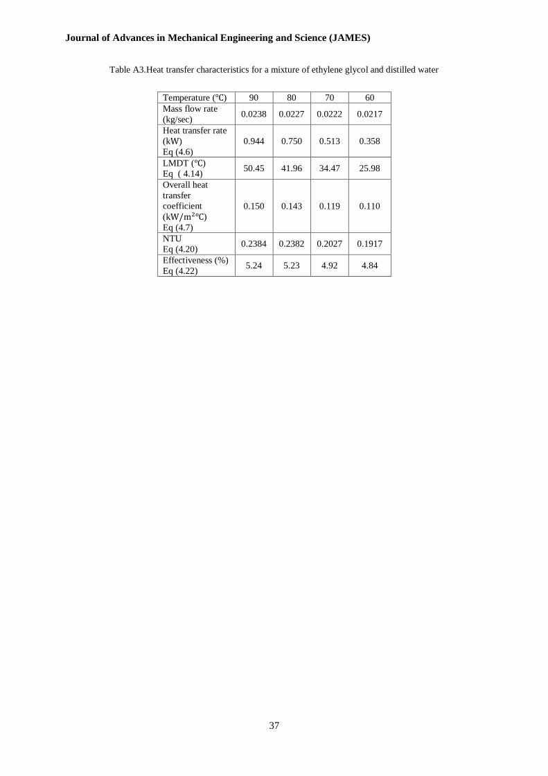
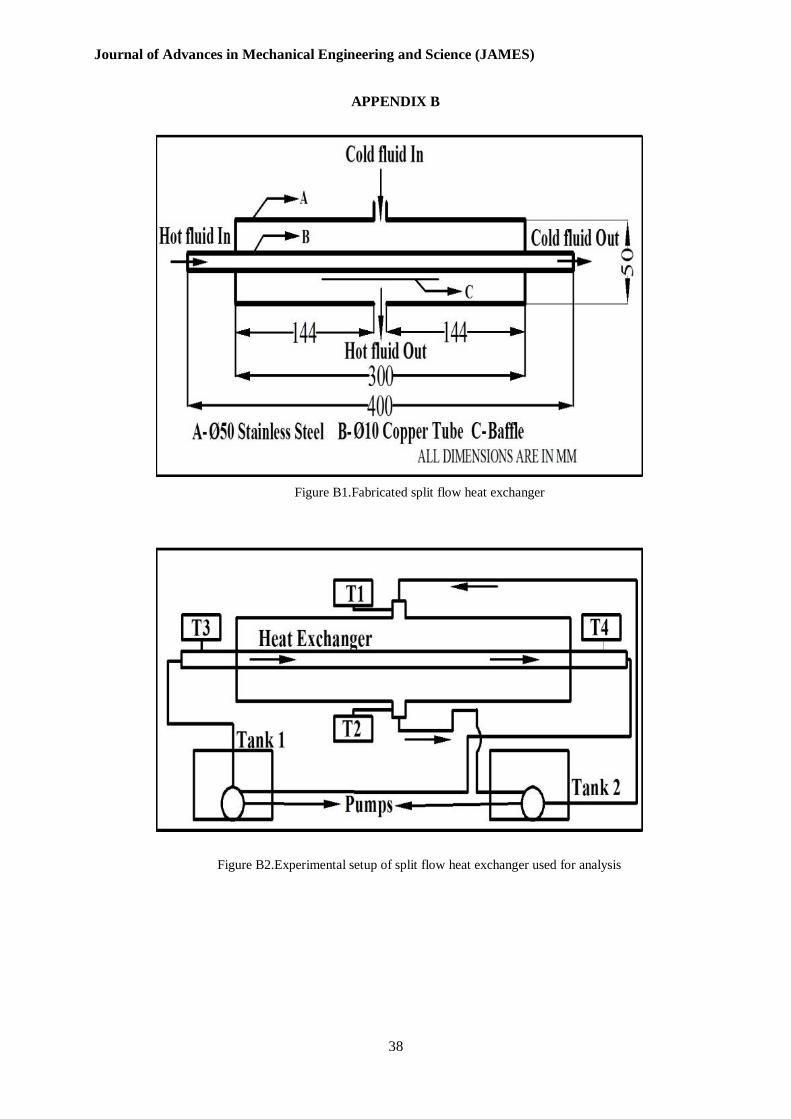
3. EXPERIMENTAL SETUP
The setup consists of an inner tube and
an outer shell. The inner tube is made of
copper and it has a length of 400mm and a
diameter of 10mm. The outer shell is made of
stainless steel and it has a length of 300mm
and diameter of 50mm. Figure B1 shows the
fabricated split flow heat exchanger and figure
B2 shows the experimental set up used for the
analysis. Four digital temperature sensors are
used to measure the inlet and outlet
temperature of the hot and cold water. Flow
control valve is used to control the flow of
fluids. Two submersible pumps are immersed
in water tanks to pump the hot fluid in to the
tube and cold fluid in to the shell.
3.1. Shell
Shell is the outermost part of the heat
exchanger in which the cold fluid carrying
nanoparticles flows and it consists of an inner
port and an outer port. The cold fluid enters the
input port and receives heat from the hot fluid
and exits via the outer port. The inner port and
outer port has a diameter of 12mm and it is
fitted in the centre part of the shell. The
material of the shell is stainless steel.
3.2. Tube
The inner tube rests inside the shell
and it gives heat to the cold fluid. The hot fluid
from the water tank enters in to the tube and
exits via the exit port. The inlet and outlet
temperatures are recorded by the digital
temperature sensor by means of a probe
attached at the inlet and outlet ports. The tube
has a diameter of 10mm. The material of the
inner tube is copper.
4. ANALYSIS OF HEAT EXCHANGERS
[26] used two methods for the analysis
of heat exchangers viz the Logarithmic Mean
Temperature Difference (LMTD) and NTU-
Effectiveness Method. The analysis is shown
by means of equations from (4.1) to (4.22)
Using first law of thermodynamics, the
rate of heat transfer from the hot fluid is equal
to the rate of heat transfer to the cold one. That
is,
( ) (4.1)
( ) (4.2)
where the subscripts c and h stands for
cold and hot fluids respectively.
, – mass flow rates of cold and hot
fluids in kg/s.
, – Specific heat rates for cold and hot
fluids in
, – inlet temperatures in
, – outlet temperatures in
It is often convenient to combine the
product of the mass flow rate and the specific
heat of a fluid into a single quantity in heat
transfer analysis. This quantity is called the
heat capacity rate and is defined for the hot and
cold fluid streams as
= (4.3)
= (4.4)
Therefore, heat transfer rate in terms
of heat capacity rate becomes
( ) (4.5)
( ) (4.6)
Journal of Advances in Mechanical Engineering and Science (JAMES)
32
In a heat exchanger the rate of heat
transfer can also be expressed in an analogous
manner to Newton’s law of cooling as
(4.7)
where is the overall heat transfer
coefficient in
, is the heat transfer
area in , is an appropriate average
temperature difference between the two fluids.
4.1. Logarithmic Mean Temperature
Difference(LMTD)
The heat transfer rate equation is given
by
(4.8)
where
( ) (4.9)
For parallel flow heat exchangers
(4.10)
(4.11)
For counter flow heat exchangers
(4.12)
(4.13)
For cross flow heat exchangers
= (4.14)
is known as the log mean
temperature difference, which is the suitable
form of the average temperature difference for
use in the analysis of heat exchangers. Here
and represent the temperature
difference between the two fluids
4.2. The Effectiveness – NTU method
It is easy to use in heat exchanger
analysis when the inlet and outlet temperatures
of the hot and cold fluids are known or can be
determined from an energy balance when we
discuss the method in log mean temperature
difference (LMTD). Once ∆Tm, the mass flow
rates, and the overall heat transfer coefficient
are available, the heat transfer surface area of
the heat exchanger can be determined from
(4.15)
Therefore, the LMTD method is very
suitable for determining the size of a heat
exchanger to realize the prescribed outlet
temperatures when the mass flow rates and the
inlet and outlet temperatures of the hot and
cold fluids are specified. With the LMTD
method, the task is to select a heat exchanger
that will meet the prescribed heat transfer
requirements. The procedure to be followed by
the selection process is as follows:
1. Select the type of heat exchanger
suitable for the application.
2. Determine any unknown inlet or outlet
temperature and the heat transfer rate
using an energy balance.
3. Calculate the log mean temperature
difference ∆Tm and the correction
factor F, if necessary. Obtain (select or
calculate) the value of the overall heat
transfer coefficient U.
4. Calculate the heat transfer surface area
.
The task is completed by selecting a
heat exchanger that has a heat transfer surface
area equal to or larger than . A second kind
of problem encountered in heat exchanger
analysis is the determination of the heat
transfer rate and the outlet temperatures of the
hot and cold fluids for prescribed fluid mass
flow rates and inlet temperatures when the type
and size of the heat exchanger are specified.
The heat transfer surface area A of the heat
exchanger in this case is known, but the outlet
temperatures are not. Here the task is to
determine the heat transfer performance of a
specified heat exchanger or to determine if a
heat exchanger available in storage will do the
job.
For this alternative problem, the
LMTD method could still used. It is not
practical because the procedure would require
tedious iterations. In 1955, Kays and London
came up with a method called the
effectiveness-NTU method, which greatly
simplified heat exchanger analysis in an
attempt to eliminate the iterations from the
solutions of such problems.
This method is based on a
dimensionless parameter called the heat
transfer effectiveness , defined as the ratio of
actual heat transfer rate to the maximum
possible heat transfer rate.
(4.16)
The actual heat transfer rate in a heat
exchanger can be determined from an energy
balance on the hot or cold fluids and can be
expressed as
( ) ( )
(4.17)
To determine the maximum possible
heat transfer rate in a heat exchanger, we first
recognize that the maximum temperature
difference in a heat exchanger is the difference
between the inlet temperatures of the hot and
cold fluids. That is,
(4.18)
Journal of Advances in Mechanical Engineering and Science (JAMES)
33
The heat transfer in a heat exchanger
will reach its maximum value when (1) the
cold fluid is heated to the inlet temperature of
the hot fluid or (2) the hot fluid is cooled to the
inlet temperature of the cold fluid. These two
limiting conditions will not be reached
simultaneously unless the heat capacity rates of
the hot and cold fluids are identical (i.e.,
).When , which is usually the
case, the fluid with the smaller heat capacity
rate will experience a larger temperature
change, and thus it will be the first to
experience the maximum temperature, at
which point the heat transfer will come to a
halt. Therefore, the maximum possible heat
transfer rate in a heat exchanger is
( ) (4.19)
where is the smaller of
= and .
Effectiveness relations of the heat
exchangers typically involve the dimensionless
group . This quantity is called the
number of transfer units NTU and is expressed
as
(4.20)
where the overall heat is transfer
coefficient and is the heat transfer surface
area of the heat exchanger. Note that is
proportional to .Therefore, for specified
values of and , the value of is a
measure of the heat transfer surface area . Thus, the larger the , the larger is the heat
exchanger.
In heat exchanger analysis, it is also
convenient to define another dimensionless
quantity called the capacity ratio c as
(4.21)
The effectiveness of the heat
exchanger for cross flow heat exchanger with
both fluids unmixed is given by the equation
* , ( ) + (4.22)
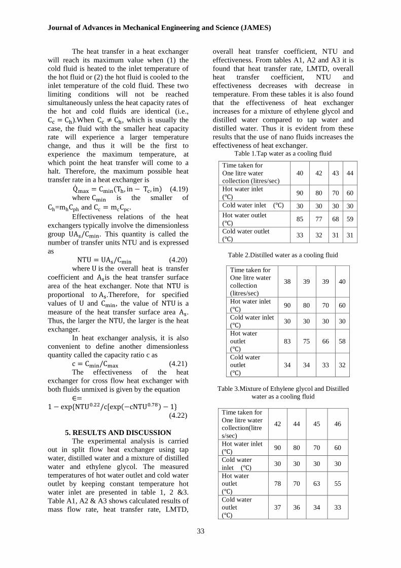
5. RESULTS AND DISCUSSION
The experimental analysis is carried
out in split flow heat exchanger using tap
water, distilled water and a mixture of distilled
water and ethylene glycol. The measured
temperatures of hot water outlet and cold water
outlet by keeping constant temperature hot
water inlet are presented in table 1, 2 &3.
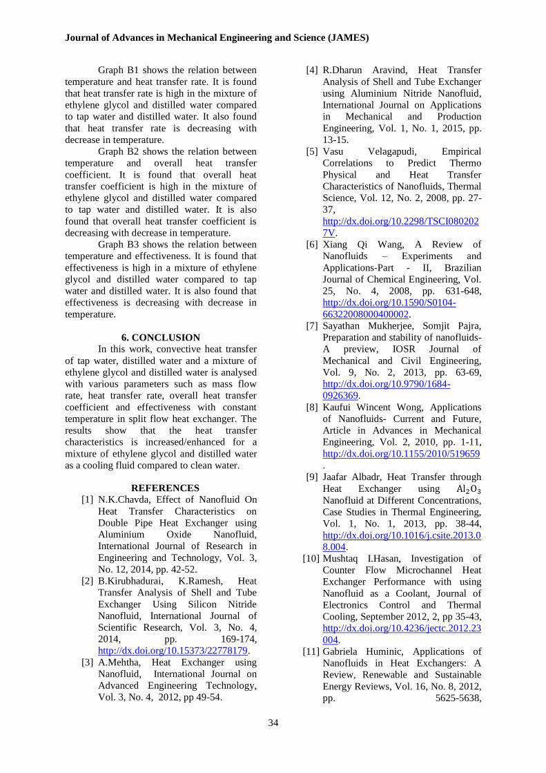
Table A1, A2 & A3 shows calculated results of
mass flow rate, heat transfer rate, LMTD,
overall heat transfer coefficient, NTU and
effectiveness. From tables A1, A2 and A3 it is
found that heat transfer rate, LMTD, overall
heat transfer coefficient, NTU and
effectiveness decreases with decrease in
temperature. From these tables it is also found
that the effectiveness of heat exchanger
increases for a mixture of ethylene glycol and
distilled water compared to tap water and
distilled water. Thus it is evident from these
results that the use of nano fluids increases the
effectiveness of heat exchanger. Table 1.Tap water as a cooling fluid
Table 2.Distilled water as a cooling fluid
Table 3.Mixture of Ethylene glycol and Distilled
water as a cooling fluid
Time taken for
One litre water
collection(litre
s/sec)
42 44 45 46
Hot water inlet
( ) 90 80 70 60
Cold water
inlet ( ) 30 30 30 30
Hot water
outlet
( )
78 70 63 55
Cold water
outlet
( )
37 36 34 33
Time taken for
One litre water
collection (litres/sec)
40 42 43 44
Hot water inlet
( ) 90 80 70 60
Cold water inlet ( ) 30 30 30 30
Hot water outlet
( ) 85 77 68 59
Cold water outlet
( ) 33 32 31 31
Time taken for
One litre water
collection
(litres/sec)
38 39 39 40
Hot water inlet
( ) 90 80 70 60
Cold water inlet
( ) 30 30 30 30
Hot water
outlet
( )
83 75 66 58
Cold water
outlet
( )
34 34 33 32
Journal of Advances in Mechanical Engineering and Science (JAMES)
34
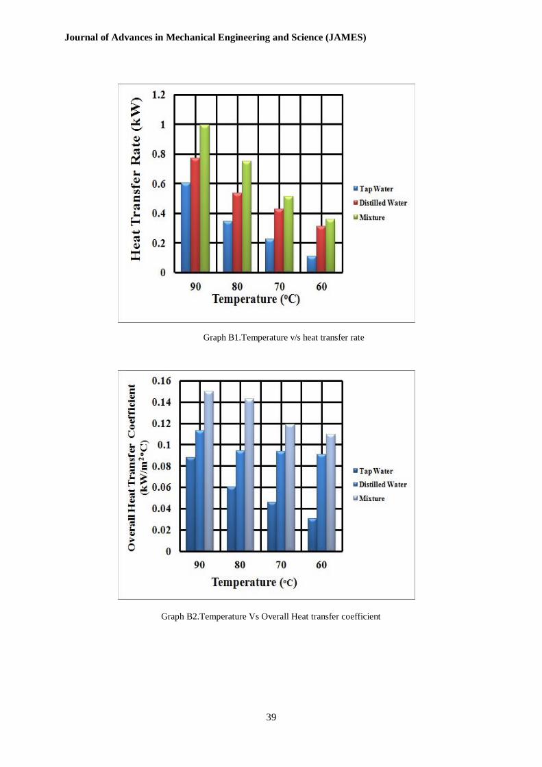
Graph B1 shows the relation between
temperature and heat transfer rate. It is found
that heat transfer rate is high in the mixture of
ethylene glycol and distilled water compared
to tap water and distilled water. It also found
that heat transfer rate is decreasing with
decrease in temperature.
Graph B2 shows the relation between
temperature and overall heat transfer
coefficient. It is found that overall heat
transfer coefficient is high in the mixture of
ethylene glycol and distilled water compared
to tap water and distilled water. It is also
found that overall heat transfer coefficient is
decreasing with decrease in temperature.
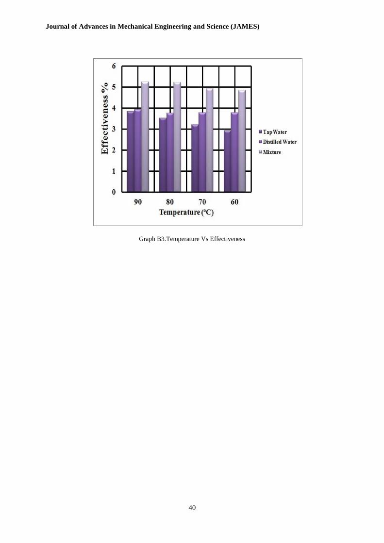
Graph B3 shows the relation between
temperature and effectiveness. It is found that
effectiveness is high in a mixture of ethylene
glycol and distilled water compared to tap
water and distilled water. It is also found that
effectiveness is decreasing with decrease in
temperature.
6. CONCLUSION
In this work, convective heat transfer
of tap water, distilled water and a mixture of
ethylene glycol and distilled water is analysed
with various parameters such as mass flow
rate, heat transfer rate, overall heat transfer
coefficient and effectiveness with constant
temperature in split flow heat exchanger. The
results show that the heat transfer
characteristics is increased/enhanced for a
mixture of ethylene glycol and distilled water
as a cooling fluid compared to clean water.
REFERENCES
[1] N.K.Chavda, Effect of Nanofluid On
Heat Transfer Characteristics on
Double Pipe Heat Exchanger using
Aluminium Oxide Nanofluid,
International Journal of Research in
Engineering and Technology, Vol. 3,
No. 12, 2014, pp. 42-52.
[2] B.Kirubhadurai, K.Ramesh, Heat
Transfer Analysis of Shell and Tube
Exchanger Using Silicon Nitride
Nanofluid, International Journal of
Scientific Research, Vol. 3, No. 4,
2014, pp. 169-174,
http://dx.doi.org/10.15373/22778179.
[3] A.Mehtha, Heat Exchanger using
Nanofluid, International Journal on
Advanced Engineering Technology,
Vol. 3, No. 4, 2012, pp 49-54.
[4] R.Dharun Aravind, Heat Transfer
Analysis of Shell and Tube Exchanger
using Aluminium Nitride Nanofluid,
International Journal on Applications
in Mechanical and Production
Engineering, Vol. 1, No. 1, 2015, pp.
13-15.
[5] Vasu Velagapudi, Empirical
Correlations to Predict Thermo
Physical and Heat Transfer
Characteristics of Nanofluids, Thermal
Science, Vol. 12, No. 2, 2008, pp. 27-
37,
http://dx.doi.org/10.2298/TSCI080202
7V.
[6] Xiang Qi Wang, A Review of
Nanofluids – Experiments and
Applications-Part - II, Brazilian
Journal of Chemical Engineering, Vol.
25, No. 4, 2008, pp. 631-648,
http://dx.doi.org/10.1590/S0104-
66322008000400002.
[7] Sayathan Mukherjee, Somjit Pajra,
Preparation and stability of nanofluids-
A preview, IOSR Journal of
Mechanical and Civil Engineering,
Vol. 9, No. 2, 2013, pp. 63-69,
http://dx.doi.org/10.9790/1684-
0926369.
[8] Kaufui Wincent Wong, Applications
of Nanofluids- Current and Future,
Article in Advances in Mechanical
Engineering, Vol. 2, 2010, pp. 1-11,
http://dx.doi.org/10.1155/2010/519659
.
[9] Jaafar Albadr, Heat Transfer through
Heat Exchanger using
Nanofluid at Different Concentrations,
Case Studies in Thermal Engineering,
Vol. 1, No. 1, 2013, pp. 38-44,
http://dx.doi.org/10.1016/j.csite.2013.0
8.004.
[10] Mushtaq I.Hasan, Investigation of
Counter Flow Microchannel Heat
Exchanger Performance with using
Nanofluid as a Coolant, Journal of
Electronics Control and Thermal
Cooling, September 2012, 2, pp 35-43,
http://dx.doi.org/10.4236/jectc.2012.23
004.
[11] Gabriela Huminic, Applications of
Nanofluids in Heat Exchangers: A
Review, Renewable and Sustainable
Energy Reviews, Vol. 16, No. 8, 2012,
pp. 5625-5638,

Journal of Advances in Mechanical Engineering and Science (JAMES)
35
http://dx.doi.org/10.1016/j.rser.2012.0
5.023.
[12] Lazarus Godson Asirvatham,
Nanofluid Heat Transfer and
Applications, Journal of Thermal
Engineering, Vol. 1, No. 2, 2015, pp
113-115.
[13] Arun kumar Tiwari, Thermal
performance of Shell and Tube heat
exchanger using nanofluids,
International Journal of Advances in
Production and Mechanical
Engineering Vol. 1, No. 1, 2015, pp.
27-34.
[14] Reza Aghayari, The Effect of
Nanoparticles on Thermal Efficiency
of Double Tube Heat Exchangers in
Turbulent Flow, Vol. 2014, 2014, pp.
1-5,
http://dx.doi.org/10.1155/2014/274560
.
[15] Hooman Yarmand, Numerical
Investigation of Heat Transfer
Enhancement in a Rectangular Heated
Pipe for Turbulent Nanofluid, The
Scientific World Journal, Vol. 2014,
2014, pp. 1-9,
http://dx.doi.org/10.1155/2014/369593
.
[16] Reza Aghayari, Heat Transfer of
Nanofluid in a Double Pipe Heat
Exchanger, International Scholarly
Research Notices, Vol. 2014, 2014,
pp. 1-7, http://dx.doi.org/10.1155/2014/736424
. [17] Bayram Sahin, An Experimental
Study on Heat Transfer and
Pressure Drop of CuO-Water
Nanofluid, Journal of
Nanomaterials, Vol. 2015, 2015, pp
1-10, http://dx.doi.org/10.1155/2015/790839
. [18] Mohammad Nasiri-lohesara, Heat
Transfer Enhancement and
Hydrodynamic Characteristics of
Nanofluid in Turbulent Flow Regime,
Journal of Energy, Vol. 2015, 2015,
pp. 1-6,
http://dx.doi.org/10.1155/2015/814717
.
[19] V.L.Bhimani, Experimental Study of
Heat Transfer Enhancement Using
Water Based Nanofluids as a New
Coolant for Car Radiators,
International Journal of Emerging
Technology and Advanced
Engineering, Vol. 3, No. 6, 2013, pp.
295-302.
[20] B.D.Dhamecha, Heat Transfer
Enhancement Using Nano Fluid - A
Review, International Journal of
Engineering Research & Technology,
Vol. 3, No. 1, 2014,
pp. 2702-2705.
[21] Nikhil S.Shrikhande, Heat Transfer
Enhancement in Automobile Radiator
using Nanofluids: A Review,
International Journal of Engineering
Research & Technology, Vol. 3,
No. 3, 2014, pp. 175-177.
[22] S.Kumar, A Review: Enhancement of
Heat Transfer with Nanofluids,
International Journal of Engineering
Research & Technology, Vol. 3, No. 4,
2014, pp. 549-557.
[23] Kiran S Bhusal, Study and
Investigation of Heat Transfer
Enhancement of Car Radiator by using
Nano Fluid – Review, International
Journal of Engineering Research &
Technology, Vol. 3, No. 10, 2014, pp.
178-185.
[24] Ritesh K. Sambare, Enhancement of
Heat Transfer in Solar Collectors with
Nanofluid: A Review, International
Journal of Engineering Research &
Technology, Vol. 3, No. 11, 2014, pp
480-484.
[25] Sunny Rach, Heat Transfer
Enhancement in Shell and Tube Heat
Exchanger by using Iron Oxide
Nanofluid, International Journal of
Engineering Development and
Research, Vol. 2, No. 2, 2014, pp.
2422-2432,
http://www.ijedr.org/papers/IJEDR140
2181.pdf.
[26] Yunus A.Cengel, Afshin and
J.Ghajar, Heat and Mass Transfer, 4
th Edition in SI units, Special
Indian Edition, Mcgraw Hill
Education, New York, United States,
pp 667-703.

Journal of Advances in Mechanical Engineering and Science (JAMES)
36
APPENDIX A
Table A1.Heat transfer characteristics for a tapwater
Table A2.Heat transfer characteristics for a distilled water
Temperature
( ) 90 80 70 60
Mass flow rate
(kg/sec) 0.0250 0.0238 0.0232 0.0227
Heat transfer
rate (k )
Eq (4.6)
0.602 0.344 0.223 0.109
LMDT ( )
Eq ( 4.14) 54.88 45.57 38.49 28.50
Overall heat
transfer
coefficient
(k )
Eq (4.7)
0.0877 0.0603 0.0463 0.0305
NTU
Eq (4.20) 0.105 0.0756 0.0518 0.0349
Effectiveness
(%)
Eq (4.22)
3.84 3.51 3.20 2.92
Temperature ( ) 90 80 70 60
Mass flow rate
(kg/sec) 0.0263 0.0256 0.0256 0.0250
Heat transfer rate
(k )
Eq (4.6)
0.770 0.535 0.428 0.313
LMDT ( )
Eq ( 4.14) 54.48 45.50 36.50 27.50
Overall heat
transfer
coefficient
( )
Eq (4.7)
0.1130 0.0940 0.0938 0.0910
NTU
Eq (4.20) 0.112 0.0953 0.0951 0.0945
Effectiveness (%)
Eq (4.22) 3.92 3.75 3.78 3.77
Journal of Advances in Mechanical Engineering and Science (JAMES)
37
Table A3.Heat transfer characteristics for a mixture of ethylene glycol and distilled water
Temperature ( ) 90 80 70 60
Mass flow rate
(kg/sec) 0.0238 0.0227 0.0222 0.0217
Heat transfer rate
(k )
Eq (4.6)
0.944 0.750 0.513 0.358
LMDT ( )
Eq ( 4.14) 50.45 41.96 34.47 25.98
Overall heat
transfer
coefficient
(k )
Eq (4.7)
0.150 0.143 0.119 0.110
NTU
Eq (4.20) 0.2384 0.2382 0.2027 0.1917
Effectiveness (%)
Eq (4.22) 5.24 5.23 4.92 4.84
Journal of Advances in Mechanical Engineering and Science (JAMES)
38
APPENDIX B
Figure B1.Fabricated split flow heat exchanger
Figure B2.Experimental setup of split flow heat exchanger used for analysis
Journal of Advances in Mechanical Engineering and Science (JAMES)
39
Graph B1.Temperature v/s heat transfer rate
Graph B2.Temperature Vs Overall Heat transfer coefficient
Journal of Advances in Mechanical Engineering and Science (JAMES)
40
Graph B3.Temperature Vs Effectiveness