analysis of outdoor led lighting’s dimming … · these efficient and innovative light sources...
TRANSCRIPT

JET 33
JET Volume 10 (2017) p.p. 33-45Issue 3, October 2017
Type of article 1.04www.fe.um.si/en/jet.html
ANALYSIS OF OUTDOOR LED LIGHTING’S DIMMING INFLUENCE ON THE
PERFORMANCE OF LED DRIVERS
ANALIZA VPLIVA ZATEMNJEVANJA ZUNANJE LED
RASVETLJAVE NA UČINKOVITOST LED KRMILNIKOVJurica PerkoR, Denis Pelin1, Danijel Topic2
Keywords: Outdoor LED lighting, LED driver, constant current driver, efficiency, THDI, dimmer control, pulsation, output voltage ripple
AbstractWith the development of new technologies, LEDs (light-emitting diodes) take a significant position in lighting due to their long-life spans and high luminous efficacy, which result in energy and mainte-nance cost savings. These efficient and innovative light sources require adequate ballast or electronic control gear, also known as LED drivers, for their operation. An LED driver provides appropriate volt-age level and current for the operation of LEDs. It converts and rectifies higher voltages of alternating current to lower voltages of direct current and regulates the current flowing through LEDs at a nomi-nal level. There are many advantages and disadvantages to using LEDs, primarily caused by LED cir-cuits and LED drivers. The dimming influence of outdoor LED lighting on the LED driver performance is analysed in this paper, specifically the testing of an LED lighting driver by changing the load level.
R Corresponding author: Jurica Perko MEng, Regional Energy Agency North, M. Krleze 81, 48000 Koprivnica, Croatia Tel.: +385 95 904 1543, E-mail address: [email protected]
1 Faculty of Electrical Engineering, Computer Science and Information Technology Osijek, Department of Electrome-chanical Engineering, Kneza Trpimira 2B, 31000 Osijek, Croatia
2 Faculty of Electrical Engineering, Computer Science and Information Technology Osijek, Department of Power Engi-neering, Kneza Trpimira 2B, 31000 Osijek, Croatia

34 JET
JET Vol. 10 (2017)Issue 3
Jurica Perko, Denis Pelin, Danijel Topic2 Jurica Perko, Denis Pelin, Danijel Topic JET Vol. 10 (2017)
Issue 3
‐‐‐‐‐‐‐‐‐‐
Results of LED driver efficiency calculated from measured input and output power, output voltage ripple measurements, and total harmonic distortion analysis are shown. Based on the measurement results, significant recommendations and concluding remarks are given.
Povzetek Z razvojem novih tehnologij je LED tehnologija (light‐emitting diodes, svetleče diode) zavzela pomemben delež v razsvetljavi, predvsem zaradi dolge življenjske dobe in visoko učinkovite svetilnosti, kar omogoča prihranke pri stroških za energijo in vzdrževanje. Tako učinkoviti in inovativni viri svetlobe za svoje delovanje zahtevajo ustrezen balast ali sklope za elektronsko krmiljenje oziroma LED krmilnike. LED krmilnik omogoča ustrezno napetost in tok za delovanje LED‐a, tako da pretvarja in gladi izmenični tok z visoko napetostjo v enosmerni tok z nizko napetostjo in vzdržuje nominalno raven toka skozi LED žarnico. Obstaja veliko razlogov za ali proti uporabi LED žarnico, kar je odvisno od LED vezij in LED krmilnikov. V članku je analiziran vpliv uporabe zatemnitve zunanje LED razsvetljave na učinkovitost LED krmilnikov. Članek predvsem opisuje preizkušanje krmilnika LED razsvetljave s spreminjanjem bremena in prikazuje rezultate učinkovitosti LED krmilnika, ki so izračunani na podlagi meritev vhodne in izhodne moči, meritev utripanja in celovite analize harmoničnega popačenja. Na podlagi rezultatov meritev so podane zaključne opombe in pomembna priporočila.
1 INTRODUCTION
As the next generation of lighting sources, LED street lighting has numerous advantages, such as high efficiency, power saving, cold start, longer lifetime, and improved brightness. LED lighting is practicable and reduces electricity consumption, resulting in cost reductions, [1]. It is distinguished by a positive impact on the environment and long life that results in maintenance cost reductions. LEDs require a low voltage DC supply, which necessitates AC/DC conversion if they are powered by an AC supply. LED drivers should meet the requirements according to the standards IEC 62384, ANSI C82‐SSL 1‐200X, and ANSI C82.77. The author of [2] recommends more stringent requirements as shown below:
1. power factor > 0.9
2. power efficiency > 85%
3. compliance with energy regulations
4. constant current output
5. high reliability
6. protection (surge, overvoltage, overload, short circuit, etc.)
7. low ripple
8. operation temperature ‐40 °C – +70 °C.
These requirements will be used in further analysis due to the fostering of energy efficiency. The requirements listed above indicate that an LED lighting driver includes the following modules: diode bridge rectifier, power factor correction (PFC), electromagnetic interference filter (EMI),

JET 35
Analysis of outdoor led lighting’s dimming influence on the performance of LED drivers Analysis of outdoor led lighting’s dimming influence on the performance of LED drivers 3
‐‐‐‐‐‐‐‐‐‐
pulse‐width modulation (PWM), overvoltage protection (OVP), overload protection (OLP) and overcurrent protection (OCP) as shown in Figure 1 and described in Table 1. As a part of the diode bridge rectifier, an LED driver also includes a negative temperature coefficient thermistor (NTC), Table 1.
Figure 1: Block diagram of the LED driver, [3]
Table 1: Basic information of LED driver modules
Rectifier Full‐wave bridge rectifier of a single‐phase supply converts the entire waveform to one of constant polarity at its output (positive or negative). It is also known as a Graetz bridge rectifier, a full‐wave rectifier using four diodes.
PFC Power factor correction is a feature that reduces the amount of reactive power generated from a lamp. It changes the waveform of current drown by a load to improve the power factor.
EMI Electromagnetic interference is a passive electronic device that is used to damp a disturbance generated by an external source that affects an electrical circuit.
NTC A NTC thermistor limits inrush current. When the circuit is closed, resistance decreases as the temperature rises, in other words, by the time, current heated thermistor, and its resistance changes to a lower value, allowing uninterrupted flow of current.
PWM Pulse‐width modulation is a modulation technique used for LED lighting intensity control. OVP Overvoltage protection is used to detect and quickly reduce the overvoltage condition to prevent damage.
OLP Overload protection is a protection against a running overcurrent that would cause overheating of the LED driver.
OCP Overcurrent protection is protection against excessive currents or current beyond the acceptable current rating of the LED driver.
There are many different types and variations of LED drivers, but they are mainly divided into two basic types:
1. constant current (CC) drivers
2. constant voltage (CV) drivers.
LEDs are driven by constant current (typically 350 mA, 700 mA or 1A) drivers that fix the current of the system and vary the voltage depending on the load of the LED or constant voltage (typically 10 V, 12 V or 24 V) drivers that require a fixed voltage, according to which the LED loads are added in parallel across the output of the driver until maximum output currents are reached. There are also LED manageable drivers that make LEDs more efficient. A manageable driver is a constant current driver that provides exact current on an LED module lower than nominal current. By applying that, it is possible to change the light intensity level.

36 JET
JET Vol. 10 (2017)Issue 3
Jurica Perko, Denis Pelin, Danijel Topic4 Jurica Perko, Denis Pelin, Danijel Topic JET Vol. 10 (2017)
Issue 3
‐‐‐‐‐‐‐‐‐‐
2 MATERIALS AND METHOD
2.1 Equipment and measuring instruments
The LED lamp used for testing is a low‐energy alternative for a 75 W high‐pressure sodium lamp. It is intended for outdoor lighting. The lamp is closed in accordance with the IP66 degree of protection, which proves its resistance to dust and water splashes. It gives natural white light, which enables much better visibility and better contrast in comparison with high‐pressure sodium lamps. The main characteristics of the tested lamp and LED driver are given in Table 2 and Table 3.
Table 2: Main characteristics of LED lamp
Parameter Unit ValueInput voltage V 230 Frequency Hz 50–60Nominal power W 40Correlated colour temperature K 4,000Color rendering index ‐ 70–80Luminous flux lm 3,000
Table 3: Main characteristics of LED driver
Parameter Unit Value Input voltage VAC 100–240 Frequency Hz 50–60 Input current A 0.8 Maximum input power W 80 Inrush current A2s 0.35 Output voltage VDC 25–50 Output current mA 1,050 Maximum output power W 52
The instruments used for measuring were a digital four‐channel storage oscilloscope (100 MHz with 1 GS/s sample rate on all channels), a high‐precision power analyser (1 MHz / 341 kHz sample rate), which is used for measuring input current, voltage, active and reactive power, power factor, THDI and output current, voltage and active power of LED driver.
To display current waveforms, current probes (AC/DC – 100 kHz, 50 mA to 100 A peak) were used.
2.2 Methodology of measurements
The main objective of these measurements is to examine the efficiency of the LED driver and to show the dimming influence on its performance. Using the above‐mentioned measuring instruments and electronic test instrument the following measuring units are recorded, and the change of characteristic waveforms over time are observed:
measured values
o input and output voltage [V]
o input and output current [mA]
o input and output power [W]
o power factor
o reactive power [VAr]
o output voltage ripple [V]
o THDI [%]

JET 37
Analysis of outdoor led lighting’s dimming influence on the performance of LED drivers Analysis of outdoor led lighting’s dimming influence on the performance of LED drivers 5
‐‐‐‐‐‐‐‐‐‐
observed change of a characteristic waveform
o input voltage
o input current
o output voltage.
Input and output terminals of observed LED lighting driver were connected to a multi‐channel power analyser that can measure both DC and AC components.
To test an LED lighting driver for different power levels, one of the possible dimming implementations (DC input, external resistor or reverse external resistor) must be used. The dimmer control may be operated via a dimmer or from an input signal of 0–10 VDC. When performing these measurements, an external resistor is used for the purpose of dimming, Figure 2. It is also known as a potentiometer, which is a three‐terminal resistor with a rotating contact that forms an adjustable voltage divider.
Figure 2: Dimmer control – external resistor [4]
The measurements were conducted between 20% and 100% of the nominal load at increments of 5%. Figure 2 shows that the lower limit of dimming is 10% of the nominal load; we chose to conduct measurements from 20% of the nominal load.
3 RESULTS AND DISCUSSION
3.1 Efficiency analysis
Efficiency analysis includes measurements of LED drivers input and output voltage, current and power starting from 20% of the nominal load to full power operation at increments of 5%. The efficiency of LED driver has been calculated by the following equation:
� � ������� ∙ 100% (3.1)
The results of measurements are presented in continuation, Table 4 and Figure 3. It was observed that efficiency decreases with decreasing load level. For loads lower than 40% of nominal load,

38 JET
JET Vol. 10 (2017)Issue 3
Jurica Perko, Denis Pelin, Danijel Topic6 Jurica Perko, Denis Pelin, Danijel Topic JET Vol. 10 (2017)
Issue 3
‐‐‐‐‐‐‐‐‐‐
efficiency rapidly decreases to almost 70%. According to [2], it is acceptable to dim LED lighting up to 35% of nominal load because an LED driver should meet power efficiency higher than 85%.
Table 4: Results of efficiency measurements
Load [%]
Input voltage [V]
Input current [mA]
Input power [W]
Output voltage [V]
Output current [A]
Output power [W]
Efficiency [%]
20 233.11 73.41 9.96 34.43 0.21 7.27 73.03 25 232.46 77.79 11.35 34.78 0.25 8.72 76.84 30 231.12 85.10 13.46 35.26 0.31 10.97 81.52 35 230.96 92.63 15.73 35.70 0.37 13.31 84.60 40 230.16 100.97 18.32 36.15 0.44 15.95 87.08 45 230.82 110.21 20.55 36.49 0.50 18.19 88.52 50 231.84 118.44 22.34 36.75 0.55 19.97 89.39 55 232.92 127.89 24.55 37.06 0.60 22.17 90.31 60 230.31 137.41 27.18 37.41 0.67 24.82 91.32 65 232.18 137.02 29.19 37.66 0.72 26.82 91.88 70 232.27 140.94 31.52 37.94 0.77 29.11 92.35 75 233.25 149.12 33.66 38.19 0.82 31.19 92.66 80 231.51 162.31 36.55 38.51 0.89 34.05 93.16 85 227.71 171.96 38.25 38.71 0.93 35.72 93.39 90 226.31 183.33 40.67 38.99 0.99 38.08 93.63 95 229.28 188.91 42.48 39.24 1.02 39.79 93.67 100 230.45 199.04 45.04 39.64 1.08 42.25 93.81
Average efficiency [%] 88.66
Figure 3: Dependence of efficiency on load level
Load level dependence on power factor and reactive power is shown as follows, Table 5, Figure 4 and Figure 5. The power factor has two stages of rapid decreasing in dependence on load level change. First one is between 70% and 55% of nominal load, and the second one is in the range from 40% to 20%. Reactive power rapidly decreases at dimming stages lower than 70% of nominal load, but most of the national utility companies still do not charge reactive power in the tariff model for public lighting.
70
75
80
85
90
95
100
20 25 30 35 40 45 50 55 60 65 70 75 80 85 90 95 100
Efficiency[%]
Load [%]

JET 39
Analysis of outdoor led lighting’s dimming influence on the performance of LED drivers Analysis of outdoor led lighting’s dimming influence on the performance of LED drivers 7
‐‐‐‐‐‐‐‐‐‐
Table 5: Results of power factor measurements
Load [%] Power factor Reactive power [VAr]20 0.5823 13.9125 0.6277 14.0830 0.6842 14.3435 0.7353 14.5040 0.7883 14.3045 0.8080 14.9950 0.8136 15.9755 0.8241 16.7260 0.8587 16.2265 0.9174 12.6670 0.9628 8.8575 0.9677 8.7780 0.9727 8.7285 0.9769 8.3790 0.9803 8.1995 0.9807 8.46100 0.9820 8.66
Figure 4: Dependence of power factor on load level
To foster energy efficiency, it is acceptable to dim LED lighting up to 65% to meet the LED driver requirement for a power factor higher than 0.9, [2]. In any case, the LED driver meets the Standard ANSI C82.77, which requires a minimum power factor of 0.5. It could be noted that reactive power is approximately constant while dimming in a range from 70% to 100% of the nominal load (Figure 5). An LED lamp, as a typical electronic end‐user device, has a capacitive load. It affects the network with reduced power delivery, which means that reactance increases losses and possibly limits the available power.
0,500,550,600,650,700,750,800,850,900,951,00
20 25 30 35 40 45 50 55 60 65 70 75 80 85 90 95 100
Power fa
ctor
Load [%]
Analysis of outdoor led lighting’s dimming influence on the performance of LED drivers 7
‐‐‐‐‐‐‐‐‐‐
Table 5: Results of power factor measurements
Load [%] Power factor Reactive power [VAr]20 0.5823 13.9125 0.6277 14.0830 0.6842 14.3435 0.7353 14.5040 0.7883 14.3045 0.8080 14.9950 0.8136 15.9755 0.8241 16.7260 0.8587 16.2265 0.9174 12.6670 0.9628 8.8575 0.9677 8.7780 0.9727 8.7285 0.9769 8.3790 0.9803 8.1995 0.9807 8.46100 0.9820 8.66
Figure 4: Dependence of power factor on load level
To foster energy efficiency, it is acceptable to dim LED lighting up to 65% to meet the LED driver requirement for a power factor higher than 0.9, [2]. In any case, the LED driver meets the Standard ANSI C82.77, which requires a minimum power factor of 0.5. It could be noted that reactive power is approximately constant while dimming in a range from 70% to 100% of the nominal load (Figure 5). An LED lamp, as a typical electronic end‐user device, has a capacitive load. It affects the network with reduced power delivery, which means that reactance increases losses and possibly limits the available power.
0,500,550,600,650,700,750,800,850,900,951,00
20 25 30 35 40 45 50 55 60 65 70 75 80 85 90 95 100
Power fa
ctor
Load [%]

40 JET
JET Vol. 10 (2017)Issue 3
Jurica Perko, Denis Pelin, Danijel Topic8 Jurica Perko, Denis Pelin, Danijel Topic
JET Vol. 10 (2017)
Issue 3
‐‐‐‐‐‐‐‐‐‐
Figure 5: Dependence of reactive power on load level
3.2 Output voltage ripple and harmonic distortion analysis
It is well known that a full‐wave bridge rectifier converts the whole of the input waveform to a constant polarity at its output, either positive or negative. It converts both polarities of the input waveform to pulsating DC, [5]. Output voltage ripple often could cause light output fluctuations, especially at the full power operation mode of an LED lighting lamp that has the greatest spread between peaks at this stage. The output voltage ripple of the tested LED lighting lamp is shown in Table 6, and the pulsating DC voltage component in comparison with the input current waveform is shown in Figure 6.
Table 6: Results of output voltage ripple Load [%]
Peak Up+[V]
Peak Up‐[V]
Output voltage ripple [V]
20 34.70 34.07 0.6325 35.09 34.37 0.7230 35.63 34.75 0.8835 36.15 35.08 1.0740 36.66 35.45 1.2145 37.05 35.72 1.3350 37.34 35.91 1.4355 37.69 36.17 1.5260 38.12 36.45 1.6765 38.50 36.64 1.8670 38.92 36.84 2.0875 39.24 37.01 2.2380 39.67 37.23 2.4485 39.92 37.37 2.5590 40.27 37.56 2.7195 40.58 37.74 2.84100 40.93 37.96 2.97
Figure 6: Pulsation of output voltage (CH2)
and input current (CH3) for 100% of nominal load
02468
1012141618
20 25 30 35 40 45 50 55 60 65 70 75 80 85 90 95 100
Reactiv
e po
wer [V
Ar]
Load [%]

JET 41
Analysis of outdoor led lighting’s dimming influence on the performance of LED drivers
JET Volume 10 (2017), p.p. 1 ‐ 10
Issue 3, 2017
Type of article: 1.04
http://www.fe.um.si/si/jet.html
9
The output voltage ripple at a load level of 100% is maximum, 3 V, which means that the light output fluctuation at this load level is the greatest.
The pulsating AC component of output voltage in comparison with the input current waveform for load level of 20%, 40%, 70%, and 100% of the nominal load is shown in continuation, Figure 7.
Figure 7: Pulsation at a) 20% b) 40% c) 70% and d) 100% of nominal load – AC voltage and
current component
An LED lighting lamp, as a digital device, brings interferences into the distribution network as a total harmonic distortion of current (THDI). Table 7 shows the share of each harmonic and total harmonic distortion for each load level (Figure 8).
The THDI measurements presented in Table 7 include only the first 15 odd harmonics that are calculated with the following equation:
���� � ����� ∙ �∑ ���������� ∙ ���
������ (3.2)

42 JET
JET Vol. 10 (2017)Issue 3
Jurica Perko, Denis Pelin, Danijel Topic10 Jurica Perko, Denis Pelin, Danijel Topic JET Vol. 10 (2017)
Issue 3
‐‐‐‐‐‐‐‐‐‐
Table 7: Harmonic analysis
Load [%] Harmonic [%] THDI [%] 1st 3rd 5th 7th 9th 11th 13th 15th
20 100.00 28.00 14.00 8.40 1.00 2.50 1.90 3.10 32.73 25 100.00 28.10 14.00 7.90 1.00 2.70 1.70 2.90 32.67 30 100.00 27.00 11.90 5.40 2.80 3.70 1.60 4.90 30.79 35 100.00 22.60 12.50 6.10 1.10 1.80 0.70 3.10 26.81 40 100.00 20.80 13.00 5.60 1.30 1.30 0.40 2.80 25.38 45 100.00 21.20 14.60 5.50 2.10 0.30 1.20 2.80 26.58 50 100.00 22.00 15.50 5.90 2.80 0.20 1.20 2.30 27.81 55 100.00 22.80 17.10 7.00 3.70 0.50 0.60 1.80 29.64 60 100.00 21.50 16.00 7.10 4.10 0.40 0.20 1.60 28.08 65 100.00 14.00 10.80 6.30 3.60 0.40 0.30 1.80 19.20 70 100.00 6.20 4.30 3.90 0.60 1.70 0.70 1.60 8.86 75 100.00 5.50 3.30 3.60 0.80 1.50 0.60 1.50 7.72 80 100.00 4.90 3.80 4.40 1.30 1.20 0.70 1.40 7.96 85 100.00 4.70 3.30 3.50 1.00 1.50 0.60 1.40 7.13 90 100.00 4.50 3.30 3.40 1.20 1.40 0.60 1.10 6.90 95 100.00 4.50 3.10 3.80 1.60 1.30 0.80 1.20 7.12 100 100.00 4.40 3.30 4.20 1.80 1.20 0.90 1.00 7.37
Figure 8: Dependence of THDI on load level
It was observed that THDI is approximately constant in the range from 70% to 100% of nominal load and does not exceed 10%. Input current waveform in comparison with input voltage waveform is shown in continuation, Figure 9.
0
5
10
15
20
25
30
35
20 25 30 35 40 45 50 55 60 65 70 75 80 85 90 95 100
THDI [%
]
Load [%]
JET 43
Analysis of outdoor led lighting’s dimming influence on the performance of LED drivers Analysis of outdoor led lighting’s dimming influence on the performance of LED drivers 11
‐‐‐‐‐‐‐‐‐‐
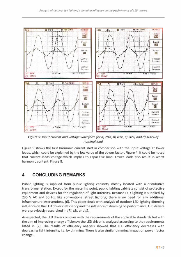
Figure 9: Input current and voltage waveform for a) 20%, b) 40%, c) 70%, and d) 100% of
nominal load
Figure 9 shows the first harmonic current shift in comparison with the input voltage at lower loads, which could be explained by the low value of the power factor, Figure 4. It could be noted that current leads voltage which implies to capacitive load. Lower loads also result in worst harmonic content, Figure 8.
4 CONCLUDING REMARKS
Public lighting is supplied from public lighting cabinets, mostly located with a distributive transformer station. Except for the metering point, public lighting cabinets consist of protective equipment and devices for the regulation of light intensity. Because LED lighting is supplied by 230 V AC and 50 Hz, like conventional street lighting, there is no need for any additional infrastructure interventions, [6]. This paper deals with analysis of outdoor LED lighting dimming influence on the LED drivers’ efficiency and the influence of dimming on performance. LED drivers were previously researched in [7], [8], and [9].
As expected, the LED driver complies with the requirements of the applicable standards but with the aim of improving energy efficiency; the LED driver is analysed according to the requirements listed in [2]. The results of efficiency analysis showed that LED efficiency decreases with decreasing light intensity, i.e. by dimming. There is also similar dimming impact on power factor change.
44 JET
JET Vol. 10 (2017)Issue 3
Jurica Perko, Denis Pelin, Danijel Topic12 Jurica Perko, Denis Pelin, Danijel Topic JET Vol. 10 (2017)
Issue 3
‐‐‐‐‐‐‐‐‐‐
As mentioned above, the LED driver comprises a full‐wave bridge rectifier, by which LEDs are modulated at twice the AC frequency. Luminous intensity is proportional to the current LED flickers at this rate. LEDs have a certain time to completely stop producing photons during the off part of the waveform, which is a negative point in comparison to other conventional light sources. Output voltage ripple analysis showed that light output fluctuations, (flickering) are more expressed in LEDs in full operation mode.
Harmonic analysis reveals that THDI is approximately constant and does not exceed 10% in the range from full power operation to operation at 70% of the nominal load. It can be observed that a huge THDI step exists at operations lower than 70%.
Generally, testing of the LED module and LED driver supported the recommendation for LED dimming possibilities in terms of energy efficiency and LED driver performance. It is recommended for LED lighting to operate at a minimum of 70% of nominal load to meet LED driver requirements according to [2]. It is also important to note that although it is possible to change the load level from 100% to 10% of nominal load (i.e. to dim LED lighting), the LED driver producer does not provide measurement results for cases from 10% to 50% in the data sheets, [4]. Obviously, the reason lies in poor values. Finally, the authors provide a conclusion: higher load leads to better energy efficiency indicators but does not have an output voltage ripple.
References
[1] J. Perko, D. Topic, D. Sljivac: Exploitation of public lighting infrastructural possibilities, Proceedings of 2016 International Conference on Smart System and Technologies, 2016, Osijek, Croatia
[2] Farnell element14: LED Street Lighting, Available: http://uk.farnell.com/led‐street‐lighting‐applications, (9 March 2017)
[3] Mean Well: 60W Single Output LED Power Supply, Available: http://www.meanwell.com/webapp/product/search.aspx?prod=CLG‐60, (10 March 2017)
[4] Inventronics: 52W Constant Current IP67 Driver, Available: http://www.inventronics‐co.com/upload/EUC‐052SxxxDV(SV)_2016041810223581211.PDF, (13 March 2017)
[5] B.W. Williams: Power electronics: devices, drivers and applications, Basingstoke: Macmillan, 1992
[6] Digi‐Key electronics: Characterizing and Minimizing LED Flicker in Lighting Applications, Available: https://www.digikey.com/en/articles/techzone/2012/jul/characterizing‐and‐minimizing‐led‐flicker‐in‐lighting‐applications, (21 March 2017)
[7] L. Yu, J. Yang: The topologies of white LED lamps’ power drivers, Proceedings of 2009 3rd International Conference on Power Electronic Systems and Applications, 2009, Hong Kong, Hong Kong
[8] C. Moo, Y. Chen, W.Yang: An Efficient Driver for Dimmable LED Lighting, IEEE Transactions on Power Electronics, Volume: 27, Issue: 11, November 2012
JET 45
Analysis of outdoor led lighting’s dimming influence on the performance of LED drivers Analysis of outdoor led lighting’s dimming influence on the performance of LED drivers 13
‐‐‐‐‐‐‐‐‐‐
[9] O. Kaplan, F. Issi, M. Ersan: A High Efficient Driver Design for LED Lighting System, 4th International Conference on Power Engineering Energy and Electrical Drives, 2013, Istanbul, Turkey
Nomenclature
η LED lighting lamp efficiency
Pout output power
Pin input power
THDI total harmonic distortion of current
I1 current of the first harmonic
In,rel relative value of n‐harmonic current in %
Analysis of outdoor led lighting’s dimming influence on the performance of LED drivers 13
‐‐‐‐‐‐‐‐‐‐
[9] O. Kaplan, F. Issi, M. Ersan: A High Efficient Driver Design for LED Lighting System, 4th International Conference on Power Engineering Energy and Electrical Drives, 2013, Istanbul, Turkey
Nomenclature
η LED lighting lamp efficiency
Pout output power
Pin input power
THDI total harmonic distortion of current
I1 current of the first harmonic
In,rel relative value of n‐harmonic current in %