analysis of local stress concentration at transitionsesistc24.mecc.polimi.it/milan_2014/wp2.pdf ·...
TRANSCRIPT

ESIS TC24 Meeting
1-2 October, 2014, POLIMI (Milano)
Aitor Landaberea
CAF S.A. – Wheels, Axles and Gearboxes Business Unit
Analysis of local stress concentration at transitions

FP7-265706 – EURAXLES Collaborative Project ESIS TC24, Milano, 2014 2
Contents
● Introduction
● Axle calculations – Current status
● Development of numerical models
● Parametric analysis of stress concentration factors
● Axle fatigue test simulation
● Complete wheelset modelling
● Conclusions and further work
FP7-265706 – EURAXLES Collaborative Project ESIS TC24, Milano, 2014 3
● To develop numerical axle modelling using the finite element method
● To analyse the main existing fatigue criteria which can be used to design axles
● To define general recommendations on the generation of numerical models
● To develop a commonly accepted numerical validation process
Introduction Objective
FP7-265706 – EURAXLES Collaborative Project ESIS TC24, Milano, 2014 4
Contents
● Introduction
● Axle calculations – Current status
● Development of numerical models
● Parametric analysis of stress concentration factors
● Axle fatigue test simulation
● Complete wheelset modelling
● Conclusions and further work

FP7-265706 – EURAXLES Collaborative Project ESIS TC24, Milano, 2014 5
● Actual EN 1310X standards apply beam calculations for axle design
● References:
● ERRI B136/RP11 (1979)
● Kammerer (1964)
● …
● Methodology:
● Method to calculate forces acting on the axle
● Method to calculate stresses in different sections of the axle
● Definition of allowable stresses
Axle calculations - Current status Introduction

FP7-265706 – EURAXLES Collaborative Project ESIS TC24, Milano, 2014 6
● General criteria: σd < σf
● σd = Dynamic stress
● σf = Allowable stress
● Kf = Fatigue SCF (material dependent)
● Kf in EN 1310X derived from tests performed by Kammerer
● σf = Allowable stresses (EA1N)
Axle calculations - Current status ERRI B136/RP11 – Calculation of stresses on the axle
Fatigue strength (MPa) SF σf (MPa)
Body 200 1.2 166
Seat 120 1.2 100

FP7-265706 – EURAXLES Collaborative Project ESIS TC24, Milano, 2014 7
● Stress concentration factor, Kt: Relation between the local stress s and the nominal
stress S.
● In bending:
)dd(
d·M·32S
4'4
● In the transition there is a biaxial stress state.
● Uniaxial Hooke’s law not applicable to strain
and stress in longitudinal direction.
● From elasticity theory:
● Local 1. principal stresses: Kt, σ1 = σ1 / S
● Local longitudinal strains: Kt,Ɛ = Ɛ × E / S
● Local equivalent stresses: Kt,σeqv = σeqv / S
Axle calculations - Current status Stress concentration factors

FP7-265706 – EURAXLES Collaborative Project ESIS TC24, Milano, 2014 8
● Kf = Fatigue SCF
● q: notch sensitivity
● Railway axles:
● Rm > 550 MPa
● R = 75 mm
Axle calculations - Current status Stress concentration factors
q ≈ 0.95
Kf ≈ Kt (confirmed by experiments)

FP7-265706 – EURAXLES Collaborative Project ESIS TC24, Milano, 2014 9
● Kammerer (SNCF) fatigue tests of axles (1/3 scale, d = 60 mm, r = 2, 5, 6, 10,
15, 25 mm) in 1960s
● Nominal stresses calculated by beam theory – No strain gauges applied
● Tests results used to define fatigue limits and shape factors (Kf) introduced in EN
13103/4
● Shape factors of Kammerer/EN standards are ≈ 20% lower than those obtained
by measurements, literature or FEA
WP2 - New axle fatigue design method Stress concentration factors
9

FP7-265706 – EURAXLES Collaborative Project ESIS TC24, Milano, 2014 10
Axle calculations – Current status Design of the transition – Influence of C on the maximum strain/stress
● For a given set of geometrical parameters, a short transition increases the
maximum stress
● Design criteria: C > Cmin. Transition length big enough to ensure that the peak
stress is at the big radius near to the end of the transition

FP7-265706 – EURAXLES Collaborative Project ESIS TC24, Milano, 2014 11
Axle calculations - Current status Stress concentration factors
● Local stresses acting on the transitions of the axles are higher than those
calculated according to EN 13103/4.
● EXPERIENCE shows that the fatigue limits of the axles based on local
stresses are higher than those established in the current standards.
ACTUAL DESIGN PROCEDURE IS SAFE
● Numerical methods needed:
● Optimization of the design of axles
● Clarifications to avoid misunderstandings.
● Real local fatigue limits needed (WP3)
FP7-265706 – EURAXLES Collaborative Project ESIS TC24, Milano, 2014 12
Contents
● Introduction
● Axle calculations – Current status
● Development of numerical models
● Parametric analysis of stress concentration factors
● Axle fatigue test simulation
● Complete wheelset modelling
● Conclusions and further work
FP7-265706 – EURAXLES Collaborative Project ESIS TC24, Milano, 2014 13
Development of numerical models Introduction
● Finite element softwares:
● Abaqus, Ansys
● Others (Cosmos, I-deas NX, CATIA)
● Development of models
● Convergence analysis
● Model validation: Comparison with experiments

FP7-265706 – EURAXLES Collaborative Project ESIS TC24, Milano, 2014 14
LR1:
3D mesh
LR2:
3D mesh
LR2:
2D axisymmetric mesh with
Fourier series expansion
Development of numerical models Models
FP7-265706 – EURAXLES Collaborative Project ESIS TC24, Milano, 2014 15
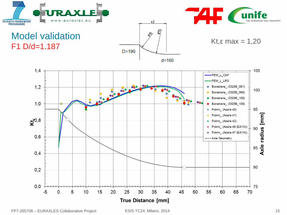
Model validation F1 D/d=1.187
Kt,ε max = 1,20

FP7-265706 – EURAXLES Collaborative Project ESIS TC24, Milano, 2014 16
Model validation F1 D/d=1.24
Kt,ε max = 1,20
FP7-265706 – EURAXLES Collaborative Project ESIS TC24, Milano, 2014 17
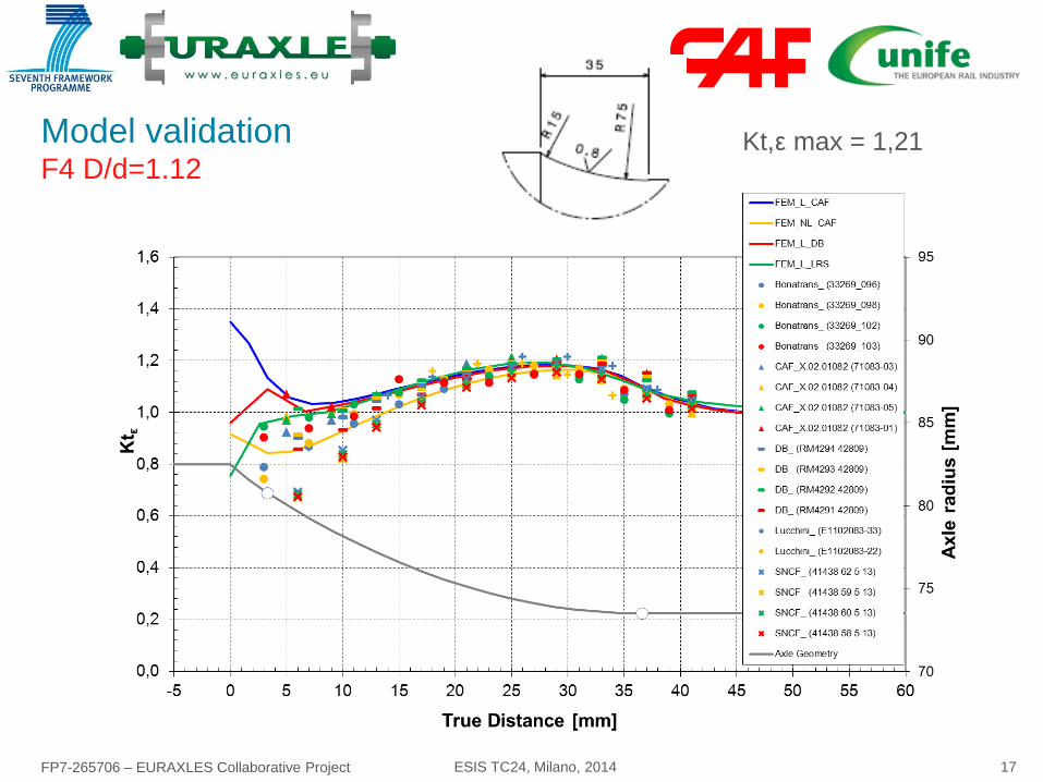
Model validation F4 D/d=1.12
Kt,ε max = 1,21

FP7-265706 – EURAXLES Collaborative Project ESIS TC24, Milano, 2014 18
Model validation F4 D/d=1.08
Kt,ε max = 1,56

FP7-265706 – EURAXLES Collaborative Project ESIS TC24, Milano, 2014 19
Model validation Motor axle F1 D/d=1.15
Kt,ε max = 1,81

FP7-265706 – EURAXLES Collaborative Project ESIS TC24, Milano, 2014 20
Model validation Kt - Summary
● Good adjustment of models
● Linear models give better
adjustment than non-linear
models (generally applicable to
high interference areas, e.g.
wheels and pinions)
FP7-265706 – EURAXLES Collaborative Project ESIS TC24, Milano, 2014 21
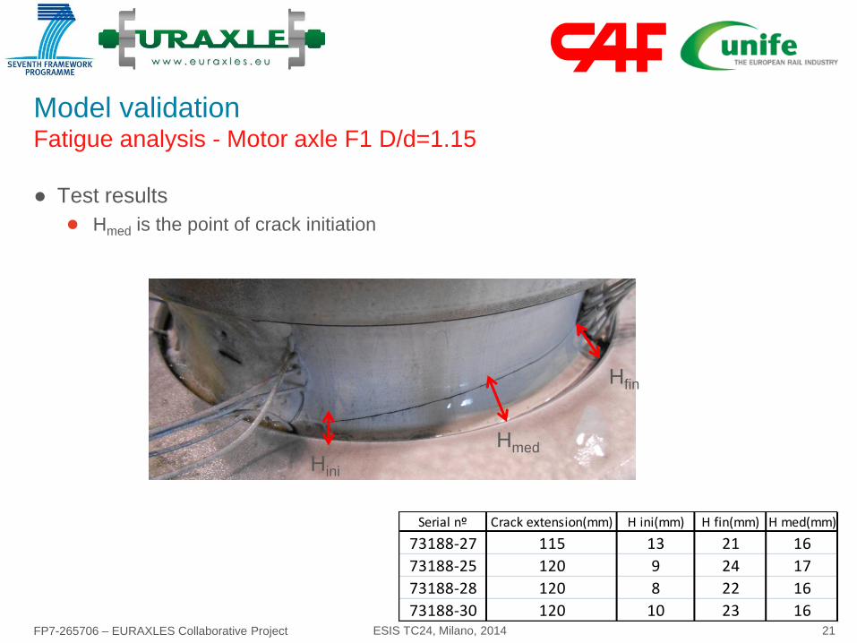
● Test results
● Hmed is the point of crack initiation
Model validation Fatigue analysis - Motor axle F1 D/d=1.15
Hini
Hfin
Hmed
Serial nº Crack extension(mm) H ini(mm) H fin(mm) H med(mm)
73188-27 115 13 21 16
73188-25 120 9 24 17
73188-28 120 8 22 16
73188-30 120 10 23 16

FP7-265706 – EURAXLES Collaborative Project ESIS TC24, Milano, 2014 22
● Principal Stresses and Dang Van Multiaxial fatigue coefficient along the transition
● CSDV non linear model > linear model (influence of mean stresses)
● CSDV non linear/ CSDV linear = 1.04
● Failure (and position) well predicted by both models
Model validation Fatigue analysis - Motor axle F1 D/d=1.15

FP7-265706 – EURAXLES Collaborative Project ESIS TC24, Milano, 2014 23
Contents
● Introduction
● Axle calculations – Current status
● Development of numerical models
● Parametric analysis of stress concentration factors
● Axle fatigue test simulation
● Complete wheelset modelling
● Conclusions and further work

FP7-265706 – EURAXLES Collaborative Project ESIS TC24, Milano, 2014 24
Parametric analysis of stress concentration factor Motivation
● K factors of EN 13103/4 should be reviewed.
● Multiple radii in typical axle transitions.
● Position of the peak stress can be in small radius
● Peak stress (and consequently Kt) may differ from bibliography data
● Objective: To derive mathematical expresions for Kt in typical simple transitions
of railway axles.
● Parametric analysis based on DOE (Design of Experiments) has been
performed.
● Geometrical constraints to avoid unfeasible combinations - final number of
combinations = 8.880

FP7-265706 – EURAXLES Collaborative Project ESIS TC24, Milano, 2014 25
Parametric analysis of stress concentration factor Results
● Output:
● Maximum values along the transition area in terms of von Mises stress, maximum
principal stress and maximum principal strain.
● Location in axial coordinates of the aforementioned variables.
● Values of the maximum stress/strain concentration factor Kt.

FP7-265706 – EURAXLES Collaborative Project ESIS TC24, Milano, 2014 26
Parametric analysis of stress concentration factor Results
● Numerical adjustment:
● Minimum transition length C:
● Kt when peak stress at R:
if C<25 mm
if C ≥ 25 mm

FP7-265706 – EURAXLES Collaborative Project ESIS TC24, Milano, 2014 27
Parametric analysis of stress concentration factor Assessment of Cmin
● Equations:
Cmin [mm]
Ore 136
UIC515-3
EN13103/4 e.g. 35
EIBFW-I Project
Euraxles
125.1
d
Dd
205,17540
170,15535
d
d
if
if
FP7-265706 – EURAXLES Collaborative Project ESIS TC24, Milano, 2014 28
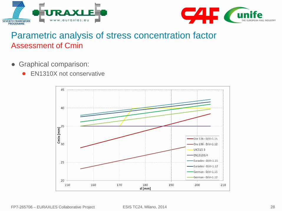
Parametric analysis of stress concentration factor Assessment of Cmin
● Graphical comparison:
● EN1310X not conservative

FP7-265706 – EURAXLES Collaborative Project ESIS TC24, Milano, 2014 29
Contents
● Introduction
● Axle calculations – Current status
● Development of numerical models
● Parametric analysis of stress concentration factors
● Axle fatigue test simulation
● Complete wheelset modelling
● Conclusions and further work
FP7-265706 – EURAXLES Collaborative Project ESIS TC24, Milano, 2014 30
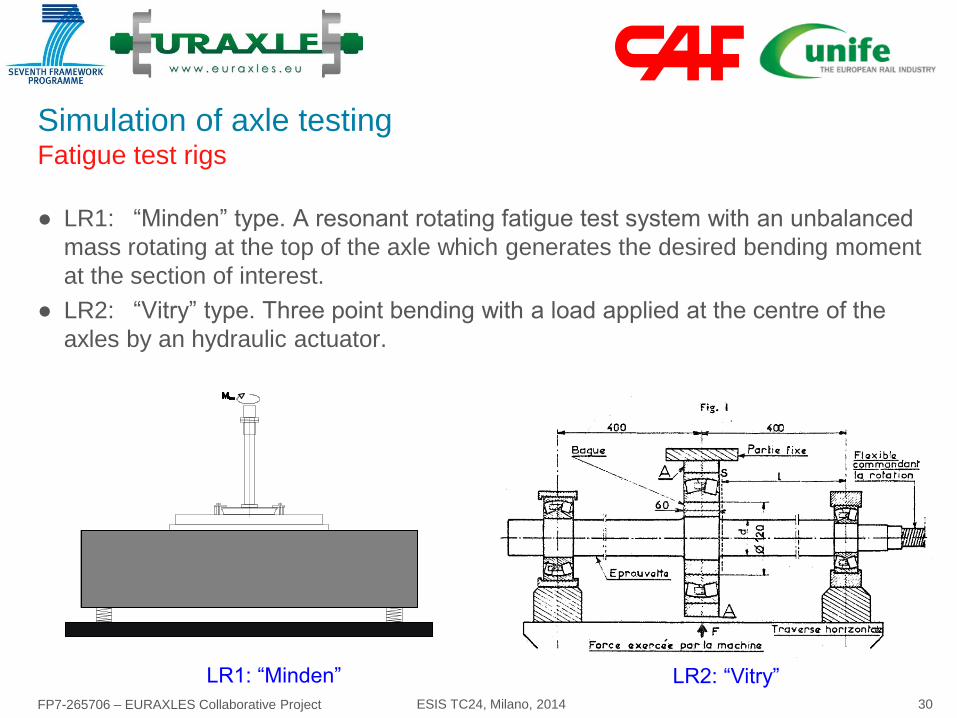
Simulation of axle testing Fatigue test rigs
● LR1: “Minden” type. A resonant rotating fatigue test system with an unbalanced
mass rotating at the top of the axle which generates the desired bending moment
at the section of interest.
● LR2: “Vitry” type. Three point bending with a load applied at the centre of the
axles by an hydraulic actuator.
LR1: “Minden” LR2: “Vitry”

FP7-265706 – EURAXLES Collaborative Project ESIS TC24, Milano, 2014 31
Simulation of axle testing Results – Transition
● Analysis:
● 2 test rigs
● Cases: M1 & M8
● Linear & Non-linear models
● Stress due to interference
(constant load)
● Same results for both test
rigs.
● Linear models: Good
prediction of value and
position of the peak stress.
● Kt factors similar in all cases.
0
50
100
150
200
250
300
185 195 205 215 225 235 245 255
x (mm)
vo
n M
ise
s S
tress (
MP
a)
70
75
80
85
90
95
100
Ax
le r
ad
ius
(m
m)
LR1-M1 LR2-M1 LR1-M1-i LR1-M1 Linear LR1-M8
LR2-M8 LR1-M8-i LR1-M8 Linear Axle geometry

FP7-265706 – EURAXLES Collaborative Project ESIS TC24, Milano, 2014 32
Simulation of axle testing Results – Seat
● Similar stress distributions in LR1 and LR2 near the axle body transition.
● LR2, symmetrical distributions theoretically predicted (conical entrance not
considered in the models)
-250
-225
-200
-175
-150
-125
-100
-75
-50
-25
0
-5 10 25 40 55 70 85 100 115 130 145 160 175 190
x (mm)
Pre
ss
ure
(M
Pa
)
LR1-M1-S22
LR2-M1-S22
LR1-M8-S22
LR2-M8-S22
-40
-30
-20
-10
0
10
-5 10 25 40 55 70 85 100 115 130 145 160 175 190
x (mm)
Sh
ea
r s
tre
ss
(M
Pa
)
LR1-M1-S12
LR2-M1-S12
LR1-M8-S12
LR2-M8-S12
Pressure Shear stress

FP7-265706 – EURAXLES Collaborative Project ESIS TC24, Milano, 2014 33
Contents
● Introduction
● Axle calculations – Current status
● Development of numerical models
● Parametric analysis of stress concentration factors
● Axle fatigue test simulation
● Model validation
● Complete wheelset modelling
● Conclusions and further work
FP7-265706 – EURAXLES Collaborative Project ESIS TC24, Milano, 2014 34
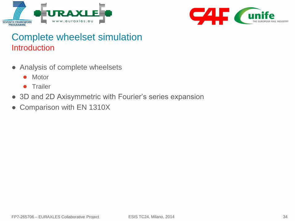
Complete wheelset simulation Introduction
● Analysis of complete wheelsets
● Motor
● Trailer
● 3D and 2D Axisymmetric with Fourier’s series expansion
● Comparison with EN 1310X

FP7-265706 – EURAXLES Collaborative Project ESIS TC24, Milano, 2014 35
Complete wheelset simulation EMU Motor wheelset - Model
● Non-linear and linear models
● Skin of shell elements for post-processing
● Calculation times high
Bending Torsion
Full model Half model
Nodes 1261532 792680
Elements 1233132 764852

FP7-265706 – EURAXLES Collaborative Project ESIS TC24, Milano, 2014 36
Complete wheelset simulation EMU Motor wheelset – Results example
● Stress distribution along the surface of the axle.
● SCF calculation. Can be applied for beam analysis (as EN 1310X)
FP7-265706 – EURAXLES Collaborative Project ESIS TC24, Milano, 2014 37
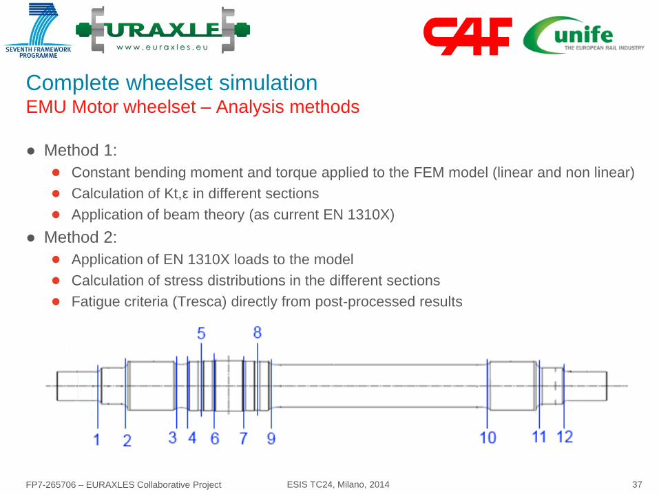
Complete wheelset simulation EMU Motor wheelset – Analysis methods
● Method 1:
● Constant bending moment and torque applied to the FEM model (linear and non linear)
● Calculation of Kt,ε in different sections
● Application of beam theory (as current EN 1310X)
● Method 2:
● Application of EN 1310X loads to the model
● Calculation of stress distributions in the different sections
● Fatigue criteria (Tresca) directly from post-processed results

FP7-265706 – EURAXLES Collaborative Project ESIS TC24, Milano, 2014 38
Complete wheelset simulation EMU Motor wheelset – Results
0
0.5
1
1.5
0 10 20 30
Kt
x (mm)
S4
Kt_L
Kt_L_tie
Kt_NL
0
0.5
1
1.5
0 10 20
Kt
x (mm)
S5
Kt_L
Kt_Ltie
Kt_NL
0
0.5
1
1.5
2
2.5
3
3.5
0 5 10
Kt
x (mm)
S6Kt_L
Kt_L_tie
Kt_NL
Conical entrance
-200
-150
-100
-50
0
50
100
150
200
0 1 2 3 4 5 6 7
Pri
nci
pal
str
ess
(M
Pa)
Angle (Rad)
S4
-150
-100
-50
0
50
100
150
0 1 2 3 4 5 6 7
Pri
nci
pal
str
ess
(M
Pa)
Angle (Rad)
S5
-150
-100
-50
0
50
100
150
0 1 2 3 4 5 6 7
Pri
nci
pal
str
ess
(M
Pa)
Angle (Rad)
S6
● Method 1
● Method 2
Linear models with mounted components too conservative

FP7-265706 – EURAXLES Collaborative Project ESIS TC24, Milano, 2014 39
Complete wheelset simulation EMU Motor wheelset – Results: Method 1
Section s ba t ta k e EF. k g E F. s 1 s 2 s2/s1 ss 1 - s 2 s allow SF K s s allow SF SF 1/SF EN
1 65.08 0.00 1.26 1.15 82.02 0.00 0.00 82.02 285 3.47 1.012 65.88 240 3.64 0.95
2 77.19 0.00 1.47 1.26 113.44 0.00 0.00 113.44 285 2.51 1.05 81 240 2.96 0.85
3 125.17 5.23 1.52 1.29 190.18 -0.24 0.00 190.42 285 1.50 1.056 132.63 240 1.81 0.83
4 125.17 5.23 1.32 1.17 165.80 -0.23 0.00 166.03 285 1.72 1.056 132.63 240 1.81 0.95
5 85.22 3.53 1.26 1.17 107.78 -0.16 0.00 107.93 285 2.64 1.295 110.73 240 2.17 1.22
6 79.23 3.27 1.54 1.38 121.92 -0.17 0.00 122.09 285 2.33 1.678 133.4 240 1.80 1.30
7 78.02 -3.27 1.54 1.38 120.30 -0.17 0.00 120.46 285 2.37 1.678 131.37 240 1.83 1.30
8 82.75 -3.53 1.26 1.16 104.35 -0.16 0.00 104.51 285 2.73 1.295 107.55 240 2.23 1.22
9 127.39 -5.60 1.21 1.12 153.98 -0.25 0.00 154.23 285 1.85 1.018 130.25 240 1.84 1.00
10 88.29 -5.60 1.35 1.16 119.29 -0.35 0.00 119.64 285 2.38 1.018 90.61 240 2.65 0.90
11 53.41 0.00 1.47 1.26 78.52 0.00 0.00 78.52 285 3.63 1.05 56.05 240 4.28 0.85
12 45.06 0.00 1.26 1.15 56.79 0.00 0.00 56.79 285 5.02 1.012 45.59 240 5.26 0.95
Nominal stressesFE values Strain-
basedMethodology 1 EN 13104
2ta2
ba2t
2n21 K4K4 tssssss ts
s
s allowSF1allow ·Ees
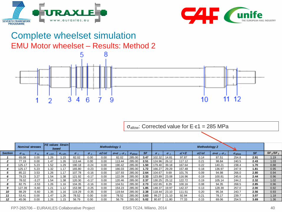
FP7-265706 – EURAXLES Collaborative Project ESIS TC24, Milano, 2014 40
Complete wheelset simulation EMU Motor wheelset – Results: Method 2
Section s ba t ta k e EF. k g E F. s 1 s 2 s2/s1 ss 1 - s 2 s allow SF s 1 s 2 e1*E s2/s1 ss 1 - s 2 s allow SF SF 1/SF 2
1 65.08 0.00 1.26 1.15 82.02 0.00 0.00 82.02 285.00 3.47 102.32 14.81 97.87 0.14 87.51 254.8 2.91 1.19
2 77.19 0.00 1.47 1.26 113.44 0.00 0.00 113.44 285.00 2.51 124.96 26.12 117.12 0.21 98.84 240.5 2.43 1.03
3 125.17 5.23 1.52 1.29 190.18 -0.24 0.00 190.42 285.00 1.50 179.40 39.18 167.64 0.22 140.21 238.4 1.70 0.88
4 125.17 5.23 1.32 1.17 165.80 -0.23 0.00 166.03 285.00 1.72 166.27 29.29 157.48 0.18 136.97 247.9 1.81 0.95
5 85.22 3.53 1.26 1.17 107.78 -0.16 0.00 107.93 285.00 2.64 104.67 9.69 101.76 0.09 94.98 266.0 2.80 0.94
6 79.23 3.27 1.54 1.38 121.92 -0.17 0.00 122.09 285.00 2.33 123.89 23.08 116.96 0.19 100.81 245.6 2.44 0.96
7 78.02 -3.27 1.54 1.38 120.30 -0.17 0.00 120.46 285.00 2.37 130.25 25.12 122.72 0.19 105.14 244.2 2.32 1.02
8 82.75 -3.53 1.26 1.16 104.35 -0.16 0.00 104.51 285.00 2.73 102.65 8.29 100.16 0.08 94.35 268.5 2.85 0.96
9 127.39 -5.60 1.21 1.12 153.98 -0.25 0.00 154.23 285.00 1.85 148.37 19.97 142.37 0.13 128.39 257.0 2.00 0.92
10 88.29 -5.60 1.35 1.16 119.29 -0.35 0.00 119.64 285.00 2.38 118.44 23.10 111.51 0.20 95.34 243.7 2.56 0.93
11 53.41 0.00 1.47 1.26 78.52 0.00 0.00 78.52 285.00 3.63 99.27 21.10 92.94 0.21 78.17 239.7 3.07 1.18
12 45.06 0.00 1.26 1.15 56.79 0.00 0.00 56.79 285.00 5.02 80.87 11.80 77.33 0.15 69.06 254.5 3.69 1.36
Nominal stressesFE values Strain-
basedMethodology 1 Methodology 2
σallow: Corrected value for E·ε1 = 285 MPa

FP7-265706 – EURAXLES Collaborative Project ESIS TC24, Milano, 2014 41
Complete wheelset simulation EMU Motor wheelset – Results: Comparison
● All methods give similar SFs in
relevant sections
● Method 1 tends to be more
conservative in simple transitions
● EN 13104 more conservative in
grooves
● Method 1 requires lower pre- and
post-processing time than
Method 2.
● Further analysis (fatigue limits)
needed

FP7-265706 – EURAXLES Collaborative Project ESIS TC24, Milano, 2014 42
Complete wheelset simulation Trailer wheelset UIC type B 22,5 t - Model
● Models: 3D and 2D axisymmetric with Fourier series expansions (Ansys)
● Stress distribution along the
transitions similar in both
models
● Calculation time 2D models
<< 3D models.
● Calculation time non-linear
models >> linear, merged
models
9054 3D 2D 2D refine
Merged nodes 3h 13min 11s 7min 4s 24min 31s
Constraint equations / 15min 0s /
Contacts Node-to-Node 2d 20h 53min 55s 1d 11h 25min 32s 2d 19h 24min 45s
Contacts Surf-to-Surf 1d 20h / /

FP7-265706 – EURAXLES Collaborative Project ESIS TC24, Milano, 2014 43
Contents
● Introduction
● Axle calculations – Current status
● Development of numerical models
● Parametric analysis of stress concentration factors
● Axle fatigue test simulation
● Complete wheelset modelling
● Conclusions

FP7-265706 – EURAXLES Collaborative Project ESIS TC24, Milano, 2014 44
Conclusions General
● Finite element modelling has been demonstrated to accurately reproduce the
stress fields acting on railway axles.
● Local stresses estimated by finite element modelling and correlated by
experimental measurements are higher than the stresses calculated according to
the actual EN 1310X standards (Kt higher than Kf defined in EN 1310X)
● At the same time, the fatigue strength in terms of local strains and stresses is
higher than considered by the standards.
● Experience shows that the actual design procedure of axles is safe.
● Complete wheelset models require large computational times, especially if non
linear conditions are introduced.
● 2D axisymmetric models with Fourier expansions reduce time

FP7-265706 – EURAXLES Collaborative Project ESIS TC24, Milano, 2014 45
Conclusions General - Modelling
● 3D or 2D with Fourier expansion can be applied
● Element type: linear elements OK
● Element size: convergence analysis should be performed to check the validity of
the models
● If peak stress at R: typical size ≈ 4 mm
● If peak stress at r: typical size ≈ 1 mm
● Post-processing
● Unaveraged results recommended to check convergence and effect of singularities
● A skin of membrane elements can be used to facilitate the analysis
● General design recommendation: peak stress at the end of the transition (R)
● Transition length C > Cmin

FP7-265706 – EURAXLES Collaborative Project ESIS TC24, Milano, 2014 46
Conclusions General - Transitions
● Transitions:
● Simple and adjacent transitions (wheel and brake disc seats) can be modelled using
tied non coincident meshes (linearised models)
● For simple and sufficiently long transitions, analytical Kt values can be applied.
● Grooves
● Contact interaction (non linear behaviour) is recommended to model the wheels, gears
and brake discs with adjacent grooves
● Recommended friction coefficient = 0.6
● Components with low interference and DN/D (bearings, labyrinths) can be removed
from the models

FP7-265706 – EURAXLES Collaborative Project ESIS TC24, Milano, 2014 47
Conclusions Proposal to complement EN 1310X
● Forces: Current EN 1310X
● Stresses:
● Applying beam theory in the different sections
● Kt
● Kt,ε
● Analytical expressions derived in EURAXLES for simple transitions
● FEA following recommendations derived in EURAXLES
● Allowable values
● F1, F3/F4: From WP3
● Safety factors: additional investigation needed
FP7-265706 – EURAXLES Collaborative Project ESIS TC24, Milano, 2014 48
Thank you for your attention