analysis of existing effectiveness and method to … · analisis terhadap system pembumian asal...
TRANSCRIPT
ANALYSIS OF EXISTING EFFECTIVENESS AND METHOD TO
ENHANCE THE LIGHTNING, SHIELDING AND EARTHING PROTECTION
SCHEMES APPLIED ON THE PARIT RAJA’S TELECOMMUNICATION
TOWER SYSTEM
CT VALKYIS BINTI MOHD KASIM
A project report is submitted in partial fulfillment of the requirements for the award
of the Degree of Master of Electrical Engineering
Faculty of Electrical and Electronic Engineering
Universiti Tun Hussien Onn Malaysia
JANUARY, 2013

v
ABSTRACT
Lightning, one of nature’s most destructive forces, continues to wreck havoc on
lives and property especially in today’s electronic environment. It has been
shown by field experiences that telecommunication towers are one of the
preferential points for direct lightning strike. This is mainly connected with the
specific features of their construction where the presence of high
telecommunication towers and their topographical location mostly at an open area
or at hills. The potential of lightning strike toward communication tower is high.
A telecommunication tower located at Parit Raja town was chosen as a case
study. The location of the tower is good to channel the coverage toward the
community. Unfortunately this tower is very vulnerable to lightning strike and
can giving impact to the surrounding buildings located nearby the tower itself
such as mosque, petrol pump, post office and the Bank Simpanan National (BSN)
bank. This thesis presents work that look at the current protection scheme against
the lightning strike and the effect on a telecommunication tower system and the
surrounding. Analysis study had been made towards existing protection
component or system and their effectiveness in mitigating the lightning strike
impact on the Parit Raja tower system. The investigation of the lightning
protection system used by the communication tower is sufficient enough to direct
the overload voltages of a lightning strike. Also, the analysis on the existing
grounding earthing system is able to accommodate and dissipate the surge current
to the earth. The method such as rolling sphere and cone protection had been used
to identify the safety area on the site due to direct strike. Some suggestions to
enhance the tower system protection such as installation external ground bus bar,
radial system, and new installation for connection of coaxial cable and
underground cable. Overall from this project, the weaknesses of system
protection were identified in the tower Parit Raja and the proposal as
improvement for the protection scheme in the future.

vi
ABSTRAK
Kilat merupakan salah satu tenaga alam semula jadi yang mampu meragut nyawa
dan menghancurkan harta benda terhadap persekitaran elektronik sekarang.
Menara komunikasi merupakan salah satu tarikan kilat yang mudah untuk
disambar oleh kilat disebabkan ciri pembinaanya yang terletak di kawasan tinggi
dan terbuka. Potensi bagi menara komunikasi untuk disambar oleh petir adalah
tinggi. Satu menara komunikasi yang terletak di Parit Raja telah dipilih sebagai
kajian kes. Lokasi menara itu adalah sangat strategik bagi menyalurkan liputan
komunikasi kepada masyarakat komuniti setempat. Malangnya, menara ini sangat
terdedah terhadap petir dan akan member kesan terhadap bangunan yang terdekat
seperti masjid, petrol pam, pejabat pos dan Bank Simpanan Nasional (BSN).
Tesis ini membincangkan sistem perlindungan terhadap petir dan kesannya
terhadap sistem menara komunikasi serta kawasan sekitarnya. Analisis telah
dibuat terhadap perlindungan komponen asal dan keberkesannya dalam
mengurangkan impak oleh panahan petir terhadap system menara pada pada Parit
Raja itu. Siasatan terhadap system perlindungan kilat yang digunakan oleh
menara komunikasi mungkinkah mencukupi bagi mengarahkan voltan beban
kilat. Analisis terhadap system pembumian asal juga dilakukan bagi menampung
dan menyisihkan lonjakan arus elektrik ke bumi. Kaedah seperti “Rolling
Spohere”dan “Kon Method” telah digunakan untuk mengenal pasti kawasan yang
selamat disebabkan lonjakan arus. Beberapa cadangan bagi meningkatkan system
perlindungan menara seperti pemasangan “external ground bus bar”,sistem
jejarian dan pemasangan kabel bawah tanah. Keseluruhan projek ini, kelemahan
oleh system perlindungan telah dikenal pasti di menara ini dan cadangan sebagai
penambah baikan bagi skim perlindungan di masa.

vii
TABLE OF CONTENTS
STUDENT’S DECLARATION ii
DEDICATION iii
ACKNOWLEDGEMENT iv
TABLE OF CONTENTS vii
LIST OF TABLES x
LIST OF FIGURES xi
LIST OF SYMBOLS AND ABBREVIATIONS xiii
CHAPTER 1 INTRODUCTION 1
1.1 Introduction 1
1.2 Problem Statement 2
1.3 Objectives 3
1.4 Scope of Project 3
1.5 Thesis Structure 4
CHAPTER 2 LITERITURE REVIEW 5
2.0 Overview 5
2.1 Lightning Over Voltages in Communication Site 7
2.1.1 Lightning Strike to the Lightning Rod or Tower 8
2.1.2 Lightning Strike to the Antenna 9
2.1.3 Lightning Strike near Ground 9
2.2 The Lightning 10

viii
2.2.1 The Creation of the Lightning 11
2.2.2 The Creation of First Stroke 12
2.2.3 The Creation of Second Stroke 14
2.3 Lightning Damage and Risk Management 15
2.4 Components of the Lightning Protection System 18
2.5 The Method of Protection System 18
2.6.1 Protection Zone Method (Cone Method) 19
2.6.2 Rolling Sphere Method 20
2.6 Protection System in Communication 21
2.6.1 External Ground Bus Bar 23
2.6.2 Tower Ground Bus Bar 23
2.6.3 Indoor Bonding 25
2.6.4 Master Ground Bus Bar (MGB) 27
2.6.5 Surge Protection for Device 28
CHAPTER 3 METHODOLOGY 30
3.1 Overview 30 26
3.2 The Flow of Project 30
CHAPTER 4 ANALYSIS OF EXISTING LIGHTNING PROTECTION 33
APPLIED ON PARIT RAJA SCHEMES
4.0 Overview 33
4.1 Case Study 33
4.1.1 The Overview of Site at Parit Raja 34
4.1.2 The Cabin 37
4.2 The Application of Rolling Sphere And 40
Protection Angle Method on Tower Parit Raja
4.3 Analysis of Existing Earth in Parit 42
Raja Tower
4.4 Analysis External Bonding for Grounding System in Tower 43

ix
4.5 Analysis to The External Ground Bus bar 44
4.6 Analysis of the Cabin 45
4.7 Propagation Time to the Communication 46
Tower in Parit Raja
4.8 Analysis the Communication Link In 48
Parit Raja Tower
CHAPTER 5 PROPOSAL ENHANCEMENT OF LIGHTNING 49
PROTECTION ON THE PARIT RAJA TOWER
5.0 Overview 49
5.1 Radial System 49
5.1.1 Recommendation of Radial System for Design 1 50
5.1.2 Recommendation of Radial System for Design 2 54
5.1.3 Recommendation of Radial System for Design 3 58
5.2 Proposal of the new External Ground Bus Bar 62
5.3 Proposal of the new connection of Coaxial cable 63
5.4 Proposal of additional earth electrode at CELCOM
and DIGI Building 64
5.5 Proposal of new location for the cable 66
CHAPTER 6 CONCLUSION AND FUTURE RECOMMENDATION
6.1 Conclusion 68
6.2 Future Recommendation 69
REFERENCES 71

x
LIST OF TABLES
Chapter 2
2.1 Review of Previous Works by Other Researches 5
2.2 The List of Effect to Typical Service 15
2.3 Summarization on the Effect at Each Point of Lightning Strike 16
2.4 Angle of Protection versus Height According To IEC 61024 19
Chapter 5
5.1 The Advantages and Disadvantages of Radial System Design 1 52
5.2 The Advantages and Disadvantages of Radial System Design 2 56
5.3 The Advantages and Disadvantages of Radial System Design 3 60
5.4 The Comparison of the Above Ground and Underground Installation 67

xi
LIST OF FIGURES
Chapter 2
2.1 The Illustration of Lightning Strike 8
2.2 The Illustration Of cloud Flash 11
2.3 The Illustration of Lightning Flash 12
2.4 The Illustrated Of Stepped Leader 13
2.5 The Illustration of Second Stroke 14
2.6 The Illustration of Source of Damage 16
2.7 Component of Lightning Protection System 18
2.8 Basic Ideal of Protection Angle Method 19
2.9 Rolling Sphere Method 20
2.10 Typical External Grounding Electrode System 21
2.11 Metal Ground Plate and Cable Entry To Facility Building Or Cabin 22
2.12 Illustration of the External Ground Bus Bar/ Metal Ground Plate 23
2.13 Typical Tower Ground Bus Bar 24
2.14 IF Cables At Close Proximity to the Radio Units 24
2.15 IF Cables To the Radio Units to Communication Building 25
2.16 Indoor Bonding Layout 26
2.17 The Ground Inside A Cabin At Jenjarum,Selangor 26
2.18 Single Point Grounding Inside the Communication Building Or Cabin 27
2.19 Typical Master Ground Bus Bas 28
2.20 Risks of Lightning Entering From External Circuits 29
2.21 Simplified Current Distribution between Services 29

xii
Chapter 3
3.1 The Flow of Project in Part 1 31
Chapter 4
4.1 The View of the Tower 33
4.2.1 Location Of The Lightning Rod 34
4.3 The Route to Earth Termination for Structure Using Steel Cable 36
4.4 The Cabin for DIGI and CELCOM 37
4.5 The Grounding for Existing Communication Building 38
4.6 The Metallic Cable Connection to the communication building 39
4.7 Application of Rolling Sphere Method toward tower 40
4.8 Protection Zone 41
4.9 Top View of Parit Raja Tower 42
4.10 Location of the Bus Bar 43
4.11 Comparison between Two Grounding System 44
4.12 Building for DIGI and CELCOM Building 45
4.13 The spread of surge current on Parit Raja tower 46
4.14 The Illustration of Cable Connection between Two Building 48
Chapter 5
5.1 The recommendation of the radial system design 1 50
5.2 The illustration of the radial system 53
5.3 The recommendation of the radial system design 2 54
5.4 The illustration of the radial system 56
5.5 The recommendation of the radial system design 3 58
5.6 The illustration of the radial system 61
5.7 The new of External Ground Bus Bar (EGB) 62
5.8 The illustration of the cable entry into the building 62
5.9 Proposed earth electrode in DIGI building 64
5.10 Proposed earth electrode in CELCOM building 65
5.11 Proposed new location of the cable 66

xiii
LIST OF SYMBOLS AND ABBREVIATIONS
mm - Millimeter
m - Meter
BSN - Bank Simpanan Nasional
MGB - Main Ground Bus Bar
EGB - External Ground Bus bar
TGB - Tower Ground Bus bar
UTHM - Universiti Tun Hussein Onn Malaysia
TNB - Tenaga Nasional Berhad
IEEE - The Institute of Electrical And Electronics Engineer
IEC - International Standard

1
CHAPTER I
INTRODUCTION
1.0 Introduction
Lightning, one of nature’s most destructive forces, continues to wreak havoc on lives
and property especially in today’s electronic environment. Lightning strikes the earth
in excess of 50 times per second [1]. On average, a lightning strike contains
approximately 50 million volts carrying 18,000–20,000 amperes of current, but
strikes with up to 300 million volts and 200,000 amps are not that uncommon [2].
Lightning can be defined as high current electric discharge which built up on cloud
near the surface of the earth during atmospheric disturbances [3].
It has been shown by field experiences that telecommunication towers are one
of the preferential points for direct lightning strikes. This is mainly connected with
the specific features of their construction where the presence of high
telecommunication towers and their topographical location mostly at an open area or
at hills. Because of high altitude of placing radio transmission antennas, lightning
strokes to the structures supporting the antennas are relatively frequent.
To protect against this destructive phenomena, a properly designed and
lightning protection system is required. The purpose of this project is to analyze the
effect of lightning strikes on an existing telecommunication tower system and also to
provide the methods to enhance the tower system protection against lightning strikes.
For this, the telecommunication tower located at Parit Raja is chosen as a
case study. In summary, this project about is study the system protection on Parit
Raja tower against the lightning strike. The analysis of the system protection is based

2
on the direct and indirect strike as well as investigated the grounding system able to
withstand the impact of the lightning strike.
1.1 Problem statement
Telecommunication system is very important for interaction and communication with
others that is far away. Therefore, all the communication equipment needs to be
protected because the signal communication originated from the tower
communication. Telecommunication towers have high tendency for lightning strike
since it basically a tall abject (approximate height) and sometimes placed at the hill
area. Further more, quite after we see it being located in the crowded area that
surrounded by building or residential (more coverage). The location of the tower is
good to channel the coverage toward the community.In Parit Raja communication
tower, in the event of shielding failure due to lightning, it might deliver the surge not
only to the system equipment, but also to the nearby area. The Parit Raja Tower is
near to community area such as the Bank Simpanan Nasional (BSN) bank, mosque,
post office, and petrol pumps etc. Therefore, the potential of induce current deliver to
this area is high.
In such a case the effects of lightning are twofold. The lightning current
flowing through the conducting parts of the whole structures and associated
grounding system creates high voltage differences between conductors. This cause a
direct and very serious danger, particularly for equipment connected to the grounding
system. Some parts of this current may flow directly through the cabling system into
the radio-transmission equipment. On the other hand, the same lightning current
creates strong electromagnetic pulses, which can generate large over voltages and
over currents in wires of electric and electronic systems.
A proper protection system is crucial to keep the equipment and electronic
system intact; avoiding system damage and hazard exposure due to the lightning
strike. The cost to repair the damage of the electrical equipment requires great sum of
amount, especially for expensive equipment such as electronic circuit, industry plan,
cable and etc.
Hence, it will be much more beneficial to spend the money in constructing
and designing an effective lightning protection system instead of fixing the damage
done by the lightning strike to the telecommunication tower.

3
1.2 Objectives
The project has used the telecommunication tower located at Parit Raja town as a
case study. Some objectives have been aimed from this project such as described
below.
i. To analyze existing protection component/ system that currently being used
their effectiveness in mitigating the lightning strike impact on the tower
system.
ii. To provide the solution in enhancing the system protection against lightning
strike impact on the tower system.
1.3 Scopes of Project
In order to achieve the mentioned objectives, several works have been highlighted
such as:
i. Literature review study covering necessary topic and theory pertaining to the
lightning protection system on the telecommunication tower.
ii. Site visit to the Parit Raja’s telecommunication tower to investigate the
existing lightning protection schemes that being applied.
iii. Conducting the simulation and analysis effectiveness of the site’s existing
protection schemes with the theoretical design information.
iv. Proposing the enhance version model of lightning protection scheme on the
site’s tower area.
v. Simulating the proposal model for verification.

4
1.4 Thesis structure
In Chapter 1 discussed about the problem of the lightning struck to communication
tower. Therefore, the plan had been made to identify the objectives and scopes in
order to facilitate the project.
In chapter 2, some previous studies have been discussed to obtain clear
information and guide for this project. Also, the basic theory in lightning creation,
the damaging of the lightning struck, the lightning protection system and the method
has been used in lightning protection scheme for enhanced the understanding.
The chapter 3 discussed about the planning of the project to ensure it would
be success. The project has divided in two parts respectively. Part 1 focused mainly
on gathering the information on the lightning protection system that was currently
used.. In part 2, discussion about the current protection system had been identified
and the proposal to overcome the weaknesses.
In chapter 4, the Parit Raja Tower communication has been chosen as case
study. The analysis and investigate have been made in enhancing the understanding
of lightning protection scheme in communication tower. The weakness of the
grounding system had been identified based on observation.
In chapter 5, after the weakness of system was identified on Parit Raja tower,
some suggestions are proposed to increase the effectiveness of the protection system.
The recommendation on the new installation for the external ground bus bar,
installation of the cable, the underground cable and the radial system for the better
protection are discussed.
5
CHAPTER 2
LITERATURE REVIEW
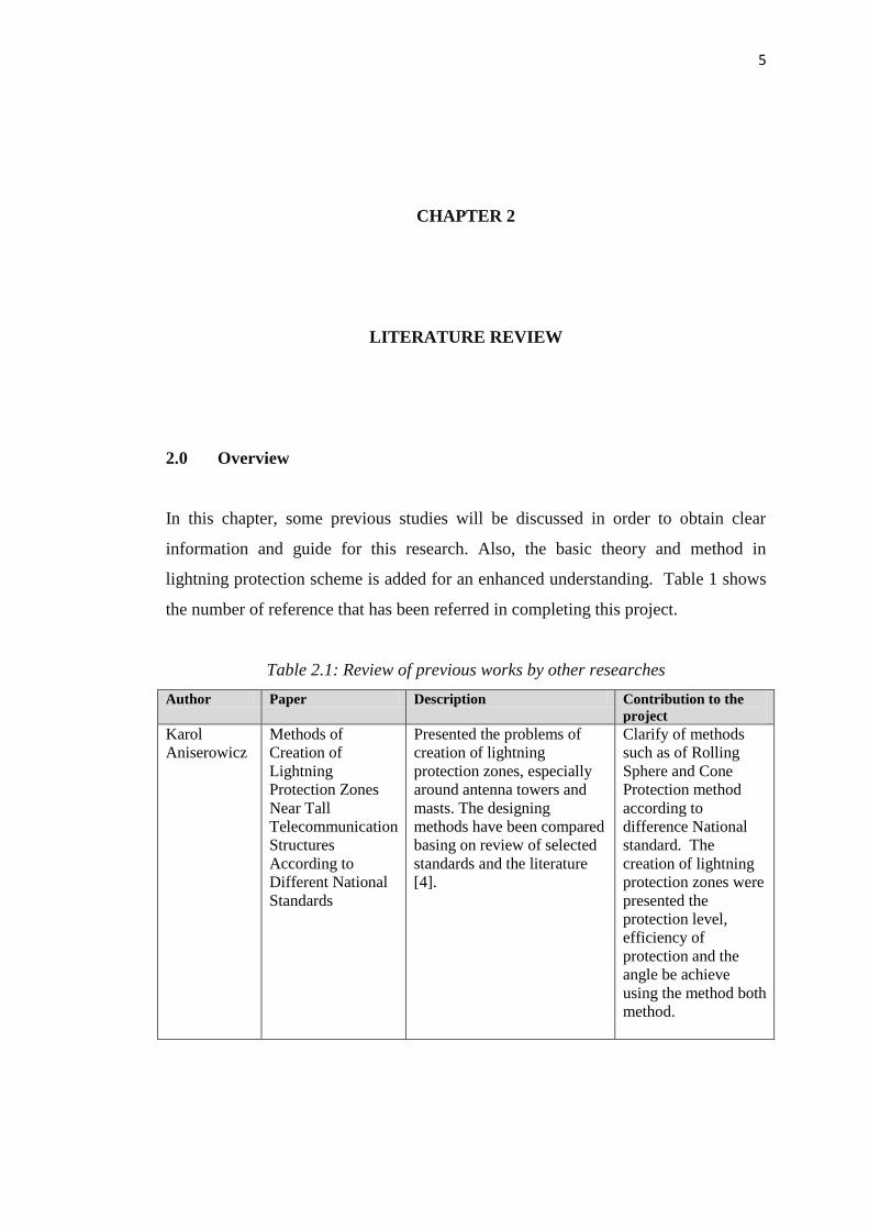
2.0 Overview
In this chapter, some previous studies will be discussed in order to obtain clear
information and guide for this research. Also, the basic theory and method in
lightning protection scheme is added for an enhanced understanding. Table 1 shows
the number of reference that has been referred in completing this project.
Table 2.1: Review of previous works by other researches
Author Paper Description Contribution to the
project
Karol
Aniserowicz
Methods of
Creation of
Lightning
Protection Zones
Near Tall
Telecommunication
Structures
According to
Different National
Standards
Presented the problems of
creation of lightning
protection zones, especially
around antenna towers and
masts. The designing
methods have been compared
basing on review of selected
standards and the literature
[4].
Clarify of methods
such as of Rolling
Sphere and Cone
Protection method
according to
difference National
standard. The
creation of lightning
protection zones were
presented the
protection level,
efficiency of
protection and the
angle be achieve
using the method both
method.

6
Table 2.1: Review of previous works by other researches (Continued)
Author Paper Description Contribution to the
project
Kai Sang
Lock
Lightning
Protection, Earthing
and Surge
Protection of Base
Transmission
Stations
This paper examines the
challenges and solutions in the
integration of lightning
protection, earthing and surge
protection for a base
transmission station
comprising a telecom tower
and an equipment cabin, taking
into consideration external
power source via overhead
Lines [5].
Clarify the protection
should be considered
in the communication
tower. Protection
against direct
lightning strikes
includes
Effective earth
termination network
for discharge of
lightning current
Integration
lightning protection
earthing systems
Extensive bonding
to prevent electric
shock
Mitigation of
ground potential rise
Prevention of
conducted surges
and into equipment
cabin
Dr. Robert
A
Durham,
PE
Lightning,
Grounding, And
Protection
For Control and
Communications
Systems
Presents of problems that
require a different perspective
from a new installation. The
paper addresses lightning,
transients, and radiation that
causes problems on
programmable logic
controllers, distributed control
systems, and remote electronic
transducers. While complex
grounding grids and networks
were not often required for
analog systems, digital
equipment requires a more
effective means of maintaining
equal potential throughout the
facility. The investigation
ranges from no air terminals to
lightning arrays. The
protection problem is
compounded when different
soils such as clay and rock are
encountered. Methods of
calculating the grounding
circuit resistance are identified
[1].
Help in terms of
understanding the of
lightning strike
creation in general, the
influence of soil type
on the grounding,
concepts lightning
protection such as air
termination, down
conductor and ground
termination which
consists of ring
system, radial system
and the earth
electrode.

7
Table 2.1: Review of previous works by other researches (Continued)
Author Paper Description Contribution to the
project
Teruo
Kageyama
Lightning Protection
Of Power
Equipment
For
Telecommunication
Lightning protection for power
equipment in order to maintain
its reliability. The Nippon
Telegraph & Telephone Public
has been investigated the
actual conditions of an
invading lightning surge, the
grounding impedance,
lightning damage, etc. The
microwave relay stations and
small scale telephone offices
which are often damaged by an
invading lightning surge. The
Nippon Telegraph &
Telephone Public further has
examined systematic lightning
protections of
telecommunication power
equipment. As a result, it was
found that enlargement of
arrester capacity,
multiinstallation
of arresters and grounding
surge impedance reduction by
using interconnected
grounding and by improving
the technique for laying
grounding wire,
etc. [7].
Clarify the the actual
conditions of an
invading lightning
surge, the actual
conditions of the
grounding system
which discharge the
lightning surge to the
ground, the lightning
damage of power
equipment and
protection method of
power equipment
against lightning
effects.
2.1 Lightning over Voltages in Communication Site
The lightning over voltage is known as fast front over voltages (FFO). Essentially,
the lightning over voltages is generated by the lightning strike [8]. Overvoltage in
communication station occurs occasionally. The lightning overvoltage is the major
one which can reduce the equipment life and leading to equipment failure. In
communication site, the over voltage can be formed in three different ways; direct
lightning strike to the antenna or radio transmission line (microwave), lightning
strike to the lightning rod or to the tower, and lightning strike to nearby ground and
induce voltages on the communication building as illustrated in figure 2.1.

8
Figure 2.1: Illustration of the lightning strike [9]
2.1.1 Lightning Strike to the Lightning Rod or Tower
When the lightning strike directly to the lightning rod or to the tower, the surge
current will flow through the down conductor and dissipated into the ground. The
impedance of the ground and the current flowing through it creates large difference
of potential (over voltages). If the rise in tower potential is significant enough, then a
flashover to the antenna and radio transmission line will occur. The over voltages
will propagate into building via cables thus damaging the equipment inside the
building.
Direct lightning stroke to the communication tower gives the higher over
voltage than the lightning stroke on distribution overhead line and also higher than
the induced voltage surge. Lightning usually attaches at the lightning rod causing
interference in other conductors. Induced over voltages by lightning on overhead
telephone line cause damages to both telephone system and electronics equipments
connected to the telephone line.
Lightning strike to
lightning rod
Lightning
strike near
the ground
Lightning
strike to
antenna

9
2.1.2 Lightning Strike to the Antenna
A direct strike to the antenna or radio transmission line will cause localised damage
to itself. The damage of this equipment is called as shielding failure, also known as
the shielding failure rate (SFR). Generally, the SFR is defined as the rate of flashes
per 100 km of line per year [8].
When an antenna tower is struck by lightning, the electric potential near the
grounding electrode rises and the lightning surge flows backward to equipment
through other grounding electrodes. Further, flashover current flows to the
distribution lines or signal lines through arresters or protection devices. In case an
antenna tower is on the roof of the station, the lightning conductor is connected to the
steel frame of the building. The lightning surge is therefore shunted to the building
and further lightning surge enters other grounding systems through contact with
equipment support hardware. The lightning surge current from direct strike on a steel
tower is about ten times as large as the lightning surge current from distribution lines
.Typically, the lightning rod is mounted on top of the tower structure. In certain
communication sites, the lightning rods are mounted near the antenna to protect it
from a direct strike.
2.1.3 Lightning Strike near Ground
When the lightning strike on the ground, it will cause an increment of the earth
potential, which can spread to the installation. Power equipment is for
telecommunications which uses for power as its input source, is easily damaged by
lightning from power distribution lines. Lightning surge can bother the
communication station for AC power line supplied for the system indirectly when
lightning hits the distribution lines and induced voltage on communication cables
which can damage the communication equipments inside the communication station.
The over voltages can affect the electrical equipment if there are no voltage
protectors [10].The lightning over voltage depends on the lightning current itself,
system parameters such as system structures, grounding resistance, grounding
methods, equipments and also the protecting equipments.

10
2.2 The Lightning
Lightning can be defined as a transient, high current discharge that builds up on
clouds near the surface of earth whose path length is generally measured in
kilometre. It occurs when some region of the atmosphere attains an electric charge
sufficiently large which come with electric field contain charge cause electrical
breakdown.
The lightning discharges, that formed in the thunderclouds and seen as a
flashes and strike toward the ground. The lightning is happen when the negative
charge in cloud become great enough, it seeks an easy path to positively charged
ground on below [11].Typically, this phenomenon occurs during bad weather in
which can be generated by volcanic eruption, dust storms and sometimes during the
snow storm.
It is common that human beings have looked at lightning as an object of awe
for it destructive capabilities and can be attractive phenomenon. It is also known that
the lightning is very dangerous because it can damage property and the most
terrifying life and death.

11
2.2.1 The Creation of the Lightning
Overhead clouds and the earth structure such as ground, tower, tall building, and tree
forms two electrodes, anode and cathode. Then, the long air column between them
reacts as the breakdown channels (phase to earth). Lightning flashes also occur
between the thunderclouds known as phase to phase. The negative charge in cloud
seeks an easy path to positively charged ground on below.
The lightning discharges can be divided into two categories which are cloud
flashes and ground flashes. The cloud flash happens when the lightning discharges
happen in cloud where it came in contacts within the thunderclouds. The cloud
flashes consist of intra cloud flashes, air discharge and inter cloud flashes as showed
in figure 2.2 [8].
Figure 2.2: The illustration of the cloud flash [8]
In ground flash, the lightning was discharged to make contact with the earth
object in which the earth objects contain of positive charges. The protections to the
equipment in power system are very important to avoid the lightning flash’s damages
in which it has destructive capability to destroy the equipment. The ground flash can
be divided into four categories which are downward negative, downward positive,
upward negative and upward positive. The ground flash is illustrated as in figure 2.3.

12
(a) (b) (c) (d)
Figure 2.3: The illustration of lightning flash [8]
(a) Downward negative
(b) Downward positive
(c) Upward positive
(d) Upward negative
The cloud contains of small and large drops of water. The large drops
(diameter less than 0.3cm) descend with higher velocity due to the gravity [8]. In the
atmosphere under fair-weather condition, the normal electric field exists. For the
charge formation in the cloud, the large drops of water are polarized by induction
with the ions exist in the cloud. This interaction caused the charges separation, where
the upper side of the cloud carries positive charges and the lower portion side carries
negative charges. The creation of the flash can be divided into two groups, the first
stroke and the second stroke [12].
2.2.2 The Creation of First Stroke
The cloud from lower portion side carries a negative charge. These clouds grow into
a thunderstorm, and contain more negative electrons form. When the storm clouds
approached the earth, where the ground underneath these clouds is positively
charged, the opposite charge will attract each other. The negative charge of the
clouds will attract more positive electrons on the ground until finally there is a large
enough charge of these opposite electrons. Then this huge energy will be released
known as lightning. The illustration can be seen as showed in figure 2.4.
Occurrence of lightning strike started when a negative charged channel jumps
out of the cloud and is called a step leader. The stepped leader moves towards the
earth in halting steps about 50 meters and after 50meter, it will pause. After that, it

13
will continue and proceed with other path. The time for each step is about 50 micro
second near the base of the cloud but decreases about 13 micro second as it
approaches the earth. The current that bought of the upward channel may exceed
200kA but has a median value about 33kA [12]. This is illustrated as in figure 2.4.
(a) (b) (c)
Figure 2.4: The illustration of the stepped leader [12]
(a) Stepped leader start
(b) Stepped leader reaches ground
(c) Upward channel moves cloud
This step leader can branch out into many different channels. The branches of
the step leader are actually looking for a place to strike and discharge the huge sums
of electrical charge. At the same time positively charged streamers are moving
upwards from trees, tower, buildings and the ground. When the positively charged
streamer connects with the negatively charged step leader, a negative charge starts to
flow down this channel and at this instant there is what being called as upward leader
(return stroke), which is the actual lightning strike. First stroke flashes may be
composed up to 54 strokes although the average is three strokes per flash. Through
our naked eye, we cannot see all the creation of lightning where we just able to see a
flash and sound that had been heard is the thunder sound [12].

14
2.2.3 The Creation of Second Stroke
The upward channel for the first stroke then reach the cloud .If there is enough
charge left after the return stroke, there is another leader that is called as dart leader
which happen in about 10 to 100 milliseconds. The dart leader will again start
downward from the cloud as illustrated in figure b and after that another portion of
charge in the cloud is discharged. Then this dart leader will continue travelling
toward ground [12].
(a) (b) (c)
Figure 2.5: The illustration of the second stroke [12].
(a) Upward channel of first stroke reach cloud
(b) Dart leader progress to ground
(c) Upward channel begin
The speed of the dart leader is much greater than the step leader in which it travels
through the ready-made ionized path that is made by the step leader. Similar to the
step leader, when the dart leader comes near to the earth, an upward channel acts
from the earth to meet it and again the current is discharged to the earth. The current
for the second stroke is approximately around 40% of the first stroke. The other
charge that is left in the cloud may send by other of dart leader to the ground, thus
another stroke of the flash happen and continues until no charges left.

15
2.3 Lightning Damage and Risk Management
No lightning protection system in this world is fully efficient. A system designed in
compliance with the standard does not guarantee immunity from damage. Lightning
protection is an issue of statistical probabilities and risk management.
Nevertheless, the basic damages actually cause the injury of living being,
physical damage and failure or malfunction of internal systems. Table 2.2 below is
the list of effects to typical type of service.
Table 2.2: The list of effect to typical service
Type of service Effect of lightning
Telecommunication Line Mechanical damage to line, melting of
screen and
conductors.
Breakdown of insulation of cable and
equipment leading to primary failure with
immediate loss of service
Secondary failures on the optical fibre
cable with damage of the cable but without
loss of service.
Power Line Damage to insulators of low voltage
overhead line, puncturing of insulation of
cable line breakdown of insulation or cable
line. Breakdown in insulation of line
equipment and or transformers, with
consequential loss of service.
Lightning Protection System (LPS) is introduced to protect the structures due
to the lightning. All concepts of damage are illustrated as in figure 2.6. Lightning
does damage to a wide range of objects and systems including electronic circuit,
overhead and underground electric power, communication system, building, and boat
[13]. In real situation, we can see all the damages caused by the lightning. The
possible sources of lightning damage are identified as followed: flashes to structure,
flashes nearby structure, flash to services and to the near services that connected to
the structure. Obviously, the effect of these flashes will cause immediate damage
mechanically [14].

16
Figure 2.6: Illustration of the source of damage
Table 2.3 below explains the type of damages and losses that occurs for each and
every point of lightning strike.
Table 2.3: Summarization on the effect at each point of lightning strike
Point of strike Source of
damage
Type of
damage
Type of losses
To structure
Flash to
supplies
structure
(S1)
D1: Injury
L1-Loss of human
L2- Economic loss
D2:
Physical
damage
L1 – Loss of human life
L2 – Loss of service
L3 – Loss of heritage
L4 – Economic loss
D3: failure
of system
L1 – Loss of human life
L2 – Loss of service
L4 – Economic loss
Next structure
Flash near
the structure
(S2)
D3– Failure
of systems
L1 – Loss of human life
L2 – Loss of service
L4 – Economic loss
S1-Lightning flash
to structure
S3-Lightning Flash
to service
S2-Lightning flash
next to structure
S4-Lightning flash near
to service

17
Table 2.3: Summarization on the effect at each point of lightning strike (continued)
Point of strike Source of
damage
Type of
damage
Type of losses
Service connected to the
structure
Flash to the
service
connected to
the structure
(S3)
D1– Injury
L1 – Loss of human life
L4 – Economic loss
D2- –
Physical
damage
L1 – Loss of human life
L2 – Loss of service
L3 – Loss of heritage
L4 – Economic loss
D3– Failure
of systems
L1 – Loss of human life
L2 – Loss of service
L4 – Economic loss
Next service
Flash near to
the service
(S4)
D3– Failure
of systems
L1 – Loss of human life
L2 – Loss of service
L4 – Economic loss
Each source of this damage may result in one or more of the damage. The
possibility injury of living being is identified due to injury to people that step and
touch voltages inside the structure been shown in table 2.3. Secondly is physical
damage that make cause fire, explosion, or mechanical destruction happen due to
thermal of lightning current effects including the triggered of the sparks cause by
over voltages inside the structure. The failure or malfunction of internal systems is
cause by Lightning Electromagnetic Impulse (LEMP) or over voltages induced on
connected lines and transmitted to structure. All of this damage is related to the loss
that happen to due to lightning such as loss of human life, loss of service to the
public, loss of cultural heritage and loss to of the economic value.
Protection measures was study which is to reduce injury of living beings due
to touch and step voltage or physical damages and reduces it from failure of the
electrical and the electronics system. The main protection was categorized which is
to protect the structure and for the services.

18
2.4 Components of the Lightning Protection System
The basis of the lightning protection principle is to effectively protect a structure
such as building, mast tower or similar self-supporting object. Based on figure 2.7, in
order to protect a structure and building against the direct strike of a lightning
basically comprises in three subsystems as below:
1. Air termination system that serves as attachment point to intercept the
lightning current.
2. Down-conductor system to bring down the lightning current safely to the
earth surface.
3. Earth termination subsystem to effectively dissipate the lightning discharge
energy into the general mass of the earth.
Figure 2.7: Component of the lightning protection System [15]
2.5 The Method of Protection System
The method of lightning protection system consists of lightning rods exposed and
placed at the highest levels of structure and connected through downward conductors
to ground system. A design method is used to identify the most suitable locations for
lightning rods.
Air
Termination
Rod
Rooftop Horizontal
Air Termination
Mesh Ring
conductor
Ring Earth
Electrode
Earth
Electrode
Down conductor

19
2.5.1 Protection Zone Method (Cone Method)
Figure 2.8: Basic ideal of protection angle method [16]
The protection angle or cone method as illustrated in figure 2.8 is often used to
determine the range of protected volume around tall constructions i.e. antenna
towers. Protection angle determined by the IEC 61024 for selected height are
presented in table 2.4.
Table 2.4: Angle of protection versus height according to IEC 61024
Protection zone or of lightning protection system may be defined as volume
that inside the cone as figure 2.8 which an air termination or lightning rod are
provided to protect it against lightning strike. The air termination or lightning rod
draws the lightning strike to it [17]. This method recognizes the attractive effect of
the air termination or lightning rod devices as a function of striking distances.
The striking distances is the length of the final jump of the step leader as it
has the potential to exceed the breakdown resistance of the last gap of the ground.
Protection
level
Efficiency Angle α of protection vs. height
h=20m h=30m h=45m h=60m
I 98% 25 * * *
II 95% 35 25 * *
III 90% 45 35 25 *
IV 80% 55 45 35 25

20
2.5.2 Rolling Sphere Method
Lightning protection is an important problem of design and maintenance of building
objects. The discharge at atmospheric is the most danger threat that should be
concerned in buildings and towers to protect all equipment and the human from this
situation.
Rolling sphere method as in figure 2.9 has described the procedure for the
determination of protected volume derived by this method. Application of the rolling
sphere method actually involved an imaginary sphere of a prescribe radius over air
termination network [6]. The sphere rolls up and over (and is supported by) air
terminal, shield wires, and other grounded metal objects intended for direct lightning
protection .The structure below the sphere as in figure 2.9 is considered to be under
protection. Equipment that touches the sphere or penetrates its surface is not
protected [6].
Figure 2.9: Rolling Sphere method [17]
Each lateral point of the structure touched by rolling sphere is a possible point
of strike. However, the probability for flashes to the sides is generally negligible for
structures lower than 60m. For taller structures, the major part of all flashes will hit
the top, horizontal leading edges and corners of the structure. Only a few portions of
all flashes will be reflected to the side of the structure. Therefore an amount
consideration should be given in installing a lateral air-termination system on the
upper part of tall structures. In this paper the rolling sphere method is applied for
positioning of air termination system for the power and desalination plant [6].

21
2.6 Protection System in Communication
The lightning protective system includes the earthing and the bonding design. The
main part of this lightning protection system is to transfer the lightning current
through the facility at the earth grounding electrode system which can be achieved by
providing highly conductive paths to direct the lightning stroke current to the earth.
The bonding of the lightning system to other grounded conductor within the building
is also important and needs to be concerned to reduce the dangerous side-flash. One
ground system in communication must be formed which can be achieved by
connecting all the ground together. By installing a radial system as illustrated in
figure 2.10 around the tower and ground loop around the equipment building (cabin),
the division of the current will be directed and dispersed through the radial system
[18].
Figure 2.10: Typical external grounding electrode system [18]
A: Grounding Radials
B. Tower Ground Bus Bar and Down
Conductor
C. Generator Grounding Conductor
D. Buried Fuel Tank Grounding Conductor
E. External Ground Bus Bar
F. Shelter Ground Ring
G. Fence Grounding Conductor
H. Ground Ring Bonding Conductors (2
minimum)
I. Tower Ground Ring
J. Earthing Electrodes (Ground Rods)
Radial system
Ground ring
Earthing
electrodes

22
The purpose of the external ground bus (Metal Ground plate or (EGB)) as illustrated
in figure 2.11 is to provide a grounding (earthing) termination point for antenna
transmission lines (coaxial cables) and other cables prior to their entry into a building
as illustrated in figure 2.11.
The purpose of the tower ground bus bar (TGB) is to provide a convenient
termination point on the tower for multiple transmission line (coaxial) grounding
(earthing) conductors as illustrated in figure 2.8. The tower ground bus bar should be
in one of the tower construction. For reduced impedance to the earth, the tower
ground bus bar can be directly bonded to the tower, using hardware of materials
suitable for preventing dissimilar metal reactions.
Surge current may also arrive to the stress equipment within the building
when the lightning strikes the communication tower. In an ideal installation all the
grounding point is all tied together with a single point ground including the tower,
bulkhead, equipment and all utilities. In order to protect all the equipment, a
protector is placed outside to prevent the incoming surge energy from the lightning
before it enters the building [19].
Figure 2.11: Metal ground plate and cable entry to facility building or cabin [19]

23
2.6.1 External Ground Bus Bar
The purpose of the external ground bus bar (EGB) as illustrated in figure 2.12 is to
provide a grounding (earthing) termination point for antenna transmission lines
(coaxial cables) and other cables prior to their entry into a building. Antenna
transmission lines and other communications cables with metallic sheaths shall be
grounded as close as practical to their point of entry into the building.
The EGB actually shall be constructed and minimally sized according to the
specific size. This EGB also need to be installed at the point where the antenna
transmission lines and other communications cables enter the building which is
connected directly to the ground electrode system using a down-conductor [18].
Figure 2.12: Illustration of the external ground bus bar/ metal ground plate [18]
2.6.2 Tower Ground Bus Bar
The purpose of the tower ground bus bar (TGB) as illustrated in figure 2.13 is to
provide a convenient termination point on the tower for multiple transmission line
(coaxial) grounding (earthing) conductors. The tower ground bus bar should be
included in of the tower construction. For reduced impedance to earth, the tower
ground bus bar may be directly bonded to the tower, using hardware of materials
suitable for preventing dissimilar metal reactions.
The TGB can be connected to the external grounding electrode system using
solid copper strap to reduce impedance to the grounding electrode system. Relatively
small copper strap has significantly less inductance (impedance to lightning) than
large wire conductors [19].

24
From the top tower equipment, the antenna and the Radio unit are attached to
the tower with mounting bracket and between of this connected via RF cable. The
Radio Unit‘s ground cable is attached to Metal Ground Plate in which it connected
(welded)to the tower. The lightning protector is installed on the Intermediate
Frequency (IF) Cables at close proximity to the Radio Units as illustrated in figure
2.14 below. The IF cable is directed from the tower toward the facility building
through the mounting blocks.
Figure 2.14: IF cables at close proximity to the radio units [19]
At the entry of the facility building as in figure 2.15, the IF cable with the
coaxial cable are attached together to the building entrance. The IF cable shield is
attached to the Metal Ground Plate and straight to the Earth Termination. The main
Figure 2.13: Typical tower ground bus bar [18]

71
REFERENCES
[1] Draadod Durham, “Lightning, Grounding, and Protection for Control and
Communications System," in Petroleum and chemical industry conference
Europe europe, 2011
[2] Sky-fire Production, Inc, “Learn More About Lightning and Thunder“
[0nline],Available:http:www.sky-fire.tv/index.cgi/lightning.html
[Assessed on : 13 March 2012]
[3] Nick P. Drozdoff, “What is Lightning “[online],Available:
http://www.newton.dep.anl.gov/askasci/phy99345.html
[Assessed on : 20 April 2012]
[4] Karol Aniserowicz,” Methods of Creation of Lightning Protection Zones
Near Tall Telecommunication Structures According to Different National
Standards”, TCSET 2002, pg 18-23,2002, Lvlv - Slavsko, Ukraine
[5] Kai Sang Lock, “Lightning Protection, Earthing and Surge Protection of Base
Transmission Stations : Pacific International Conference on Lightning,
November 1-4, 2011, Chengdu, China.
[6] P. Velmurugan, K.Dhayalasundaram, K.Ilangovan, “Application of IEC
62305 to a large Power and Desalination Plant -Lightning Protection
System”, 2011, pg 308 – 313
[7] Teruo Kageyama “Lightning Protection Of Power Equipment For
Telecommunications ”, IEEE Conference Publications 1982, Pg 334 – 341

72
[8] High voltage slide engineering, “Insulation Coordination”, University of Tun
Hussein Onn Malaysia (UTHM), Johor, Malaysia.
[9] Eritech, “Grounding, Lightning Protection and Surge Protection For
Telecommunications”, 2009 ERICO International Corporation.[online]:
Available:www.Erico.com. [Assessed on : 13 October 2012]
[10] Legrand,”Protection Against Lightning Effects”,Power Guide ,World
Headquarters and International Department Limoges Cedex – France (2009)
[11] Science Made Simple, what is Lightning [online], Available:
http://www.sciencemadesimple.co.uk/page179g.html
[Assessed on: 12 March 2012]
[12] Andrew R. Hileman, 1999” Insulation coordination For Power System”,CRC
Press Taylor & Francis Group , ISBN 0824799577.
[13] Vladimir A. Rakov and Martin A. Uman, ”Lightning Physic and Effect, First
Publisher, Cambrige University Press,United Kingdom,ISBN 0521 58327
6,2003
[14] Eritech, Lightning Protection Consultant Handbook Designing to the IEC
62305 Series of Lightning Protection Standards, 2009 ERICO International
Corporation.[online]:
Available : www.erico.com [Assessed on: 22 July 2012]
[15] Elya B. Joffe, Kai Sang Lock, “Ground For Grounding, A Circuit to System
Handbook, :IEEE Press Editorial Board,A John Wiley &
Son,INC.,Publication, ISBN 978-0471-66008-8,2010
[16] Karol Aniserowicz,” Methods of Creation of Lightning Protection Zones
Near Tall Telecommunication Structures According to Different National
Standards”, TCSET 2002, pg 18-23,2002, Lvlv - Slavsko, Ukraine

73
[17] [email protected], A Basic Primer in Lightning Effects and
Protection[online],Available:http://www.weighingsystems.com/TechnologyC
entre/Lightning1.pdf [Assessed on: 22 March 2012]
[18] Motorola, “Standard and Guidelines for Telecommunication
Sites”‟Handbook@2005, 68P81089E50-B.
[19] Alvarion,”Lightning Protection”, white Paper copyright 2005 Hand book,
DN0855
[20] Giuseppe Airoldi, Albert0 Geri And Giuseppe Maria „”Em1 Analysis in
Telecommunications Due To The Lightning Protection System, INTELEC'91
(Nov. 199 1 )
[21] Mr. Sheuan Chuang Kwong,” Telecommunication Tower” [online].
Available:http://www.alibaba.com/ telecommunication/tower
[Assessed on: 31 March 2012]
[22] Eric Holzman, “Essentials of RF and Microwave Grounding, British Library
Cataloging in Publication Data, ISBN-10: 1-58053-941-6, 2006
[23] S.F. Visacro, A. J. Soares and M.A.O Schroeder, “An interactive
computational code for simulation of transient behavior of electric system
components for lightning currents”, in Proc. ICLP 2002, International
Conference on Lightning Protection, Cracow, Poland, 2-6 September.
[24] Jacqueline Damas, Nerey. H. Mvungi, Mighanda. J. Manyahi,”Lightning
Strike on Overhead Telephone Line:A Case Study of Tanzania
Telecommunication Company Limited (TTCL)
[25] Creative Commons Attribution-ShareAlike License,” Earth potential rise”
[online], Available:
http://en.wikipedia.org/wiki/Earth_potential_rise [Assessed on: 29 Jun 2012]

74
[26] P.Y. Okyere, Ph.D & *George Eduful Kwame Nkrumah University of
Science and Technology Kumasi-Ghana. “Evaluation of Rolling Sphere
Method Using Leader Potentia Concept: A Case Study”, INTERTECH
Conference,2006
[27] Nelson Theethayi, Rajeev Thottappillil,” Currents in Buried Grounding Strips
Connected to Communication Tower Legs during Lightning Strikes”,IEEE
Transactions on Dielectrics and Electrical Insulation Vol. 15, No. 4; August
2008
[28] Yasuo Kishimoto “Consideration of protection angle method and lightning
protection rules for sides of high-rise buildings in IEC 62305 standard”, NTT
Facilities Research Institute Inc.
[29] A. S. Ahmad, T. Aka-Ngnui,” Lightning Induced Voltage on Telephone
Cables and Power Systems”, International Conference on Power Systems
Transients (IPST‟07) in Lyon, France on June 4-7, 2007