analysis of energy absorption tubes (crush … · gone for dynamic analysis. ... subjected to the...
TRANSCRIPT

International Research Journal of Engineering and Technology (IRJET) e-ISSN: 2395-0056
Volume: 04 Issue: 09 | Sep -2017 www.irjet.net p-ISSN: 2395-0072
© 2017, IRJET | Impact Factor value: 5.181 | ISO 9001:2008 Certified Journal | Page 786
ANALYSIS OF ENERGY ABSORPTION TUBES (CRUSH CAN)
Upkar mane1, Prof. S.S. Mashyal2
1Post Graduate Student, Department of Mechanical Engineering, MMEC Belgaum, Karnataka, India 2Professor, Department of Mechanical Engineering, MMEC Belgaum, Karnataka, India
---------------------------------------------------------------------***---------------------------------------------------------------------
Abstract- Thin-walled Energy Absorption tube are extensively used as energy absorbers in numerous automotive and aerospace applications as a result of their higher energy absorption capacity. Energy Absorption tube are connecting between Front bumper and Dash Toe pan. They are one of the structural members which will absorb high energies in frontal impact, so that impact energy won’t transmit to driver/passengers. Consider the energy absorption through dynamic impact, Speed of impact & momentum of impact are influential factors. The analysis has done quasi-static analysis whereas some have gone for dynamic analysis. Energy Absorption tube length, and tube cross-sectional aspect ratio, along with friction and impacting mass on crashworthiness parameters such as specific energy absorption contact time, peak force and crush distance. The impact velocity is assumed to be constant at 15 m/s. The various section aluminum tubes analysis was carried out by using finite element analysis. After providing the necessary interactions and performing meshing, the whole model is run for dynamic explicit code using LS DYNA. Key Words- CAD, FEA, Crash Analysis
1.INTRODUCTION Safety of the occupants of vehicles has continuously been a priority in automobile design. Earlier efforts during this direction were focussed on developing systems and parts for preventing accidents. Future stage of development was to make a safer close for restrained occupants. Post 1960, with legislated safety rules, crashworthiness of automobile structure became focus of attention. Saving of vehicles additionalattention. Saving of vehicles additional necessitated development of novel structural designs to boost occupier safety. One of the structural designs used conspicuously for controlling slowing and energy absorption consists of tubes destined within the longitudinal direction. Within the event of a frontal crash, these tubes, subjected to compressive axial loading, fail through through crippling of the walls and corners. Energy dissipated during this process helps reduce kinetic energy of the vehicle, and ultimately brings it to a stop. Post-crippling kinematics of the tube and resisting load generated by it depends on geometric dimensions of the cross-sectional and yield strength of the material. A typical tube deformation pattern and corresponding load-time characteristics for a crush under dynamic loading. Slowing of the vehicle depends
on this force. Since potential of injuries to occupants, either due to restraint force or impact with the inside, is directly proportional to vehicle slowing, limiting magnitude of this force may be a key goal in design. Design of those tubes involves correct proportioning of 2 sides of rectangular cross-sectional, wall thicknesses and corner geometry and non-linear properties of the material. With no easy analytical answer out there for this complicated drawback, in earlier years, designers depended heavily on testing to come back up with needed tube designs. This was a protracted, tedious and costly process prototypes testing. The crash of a car is nowadays of great important. Strict standards have to be compelled to be adhered to within the trade, above all to guard human life. The aim to improve better performance, the design variables of vehicles and higher protection capabilities for driver and passengers. So on decrease design time, Reduce Prototype and Improve design standards of crash and crush of vehicles, and components, tests are generally performed in numerical simulations. The crash and crush analysis or tests results are used for entire improvement of a replacement design. The FEA simulation results whereas not manufacturing any physical model, and should be performed quickly. This enables Design optimisation of the vehicle components before an physical model of the vehicle must be built. The foremost necessary development is to absorb the kinetic energy during a crash situation . Crash tubes are designed for absorb max. kinetic energy and convert max kinetic energy into plastic strain energy under different loading conditions. During the axial crashing and crushing behaviour of tubes or structure. 1.1 FEA Analysis This paper presents the FEA of the Energy absorption tubes of a passenger car. Front rails connect between Dash Toe pan and Front bumper. It is a structural members which will absorb high kinetic energy during front impact, so that impact energy won’t transmit to driver/passengers. The material is used for rails Steel. The whole meshing, deck preparation and the solution is run in dynamic explicit code using ABAQUS 6.11 PR3. The results of Kinetic Energy, Strain Energy, Total Energy and Internal Energy are compared with that of standard square tube. It was found that Kinetic
International Research Journal of Engineering and Technology (IRJET) e-ISSN: 2395-0056
Volume: 04 Issue: 09 | Sep -2017 www.irjet.net p-ISSN: 2395-0072
© 2017, IRJET | Impact Factor value: 5.181 | ISO 9001:2008 Certified Journal | Page 787
Energy decreased with time, Internal Energy increased with time, and Total Energy of the system remained the same. The SEA is calculated for two different velocities i.e. at 20 and 30 mph and different material aluminium and steel.
2. OBJECTIVE AND SCOPE OF THE WORK
2.1 Objective of Project The objective of this project is to find the effect of
impact on different types of Energy Absorption tubes.
Ability of vehicle structure and Subsystems to guard the occupants in survivable Crashes with affordable slowing pulse.
Restrain system give extra protection to reduce injury to occupier.
To investigate effect axial crush behavior of various structures energy absorption aluminium
tubes through finite element analysis and experimen
2.2 Scope of Project:
•Study of Energy Absorption tubes •Design of Energy Absorption tubes •Finite element Meshing, loading, boundary conditions etc. • Finite element Analysis
2.3 FE Model-
The CAD geometry of crush can as shown in fig 4.2 is imported as an input in <.stp> form into Hypermesh for the preparation of meshing. The sensitive region has been remeshed by manually considering shape and size of part. 3D model is prepared by using Pro-W Creo2.0. The CAD Model of Crash tube specification is Length-200mm, Width-38.1mm, Height- 63.5mm and thickness 1.6mm.
Fig -1: Schematic of a CAD model
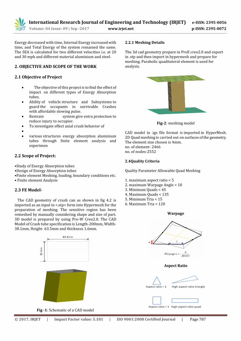
2.2.1 Meshing Details The 3d cad geometry prepare in ProE creo2.0 and export in .stp and then import in hypermesh and prepare for meshing. Parabolic quaditateral element is used for analysis.
Fig-2: meshing model
CAD model in .igs file format is imported in HyperMesh. 2D Quad meshing is carried out on surfaces of the geometry. The element size chosen is 4mm. no. of element- 2466 no. of nodes-2552 2.4Quality Criteria Quality Parameter Allowable Quad Meshing 1. maximum aspect ratio < 5 2. maximum Warpage Angle < 10 3. Minimum Quads < 45 4. Maximum Quads < 135 5. Minimum Tria < 15 6. Maximum Tria < 120
Warpage
Aspect Ratio

International Research Journal of Engineering and Technology (IRJET) e-ISSN: 2395-0056
Volume: 04 Issue: 09 | Sep -2017 www.irjet.net p-ISSN: 2395-0072
© 2017, IRJET | Impact Factor value: 5.181 | ISO 9001:2008 Certified Journal | Page 788
Skew
Jocobian
2.5 Material Properties Material is one of the important properties that define the behaviour of geometry. An aluminium material was wont to describe the material behaviour of Tubes in dynamic analysis.
Material properties used are described below For Tubes – aluminium Al6063 Young’s modulus = E= 6.9×10e4MPa, Poisson ratio = μ =0.33, Density of steel = ρ = 2.8×10e-9 tons/mm3 Yield strength= 210MPa Ultimate strength= 234MPa % of elongation= 12.8
2.6 Boundary Conditions: The boundary condition that's used here includes totally different kind of loads, i.e. Constraints, supports or boundary field specification. The Aluminium tube one end is constraint in all rotational and translational dof of all nodes on tube edge (rigid body). The another end of aluminium tube can constraint in five degree of freedom which can move axially towards the fixed plate or except the direction of the moving impact. At the fixed end reactions is calculated and other end on (moving plate) impactor.
Fig-3: Loading
The Impactor was modelled only linear displacement is allowable can move axially towards the fixed plate. Other linear and rotational dof are constraint. The energy absorbing structure is capable to absorbing max crash energy can be absorbed by two aluminium tubes is much less than 50 %.
Chart-1: Prescribed displacement of 150mm Given to movable platen in the direction of Tube axis.
3. RESULTS 3.1 Square Section Dynamic explicit analysis on the passenger car aluminium crush can at velocities 15m/s. when the accident or front impact of energy absorption tubes at the displacement determined was a hundred and fifty millimetre. Axial deflection structural behaviour of the crash can subjected to the initial speed of 15 m/s. The deflection obtained from FEA solutions are shown in Figure and validate with the experimental testing. within the explicit solution, the collapse at the highest has been predicted but the deformations close to the centre of the tube. Energy absorb by axial loading is higher than oblique loading because axial loading subjected to bending and compressive nature.
International Research Journal of Engineering and Technology (IRJET) e-ISSN: 2395-0056
Volume: 04 Issue: 09 | Sep -2017 www.irjet.net p-ISSN: 2395-0072
© 2017, IRJET | Impact Factor value: 5.181 | ISO 9001:2008 Certified Journal | Page 789
Chart-2: Energy Graph
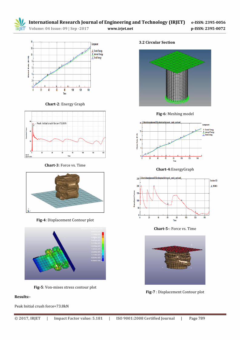
Chart-3: Force vs. Time
Fig-4: Displacement Contour plot
Fig-5: Von-mises stress contour plot
Results:- Peak Initial crush force=73.8kN
3.2 Circular Section
Fig-6: Meshing model
Chart-4:EnergyGraph
Chart-5-: Force vs. Time
Fig-7 : Displacement Contour plot
International Research Journal of Engineering and Technology (IRJET) e-ISSN: 2395-0056
Volume: 04 Issue: 09 | Sep -2017 www.irjet.net p-ISSN: 2395-0072
© 2017, IRJET | Impact Factor value: 5.181 | ISO 9001:2008 Certified Journal | Page 790
Fig-8: Von-mises stress contour plot
Results:- Peak Initial crush force=205kN 3.3 Rectangular Section
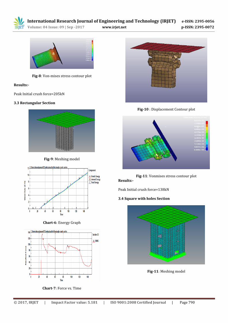
Fig-9: Meshing model
Chart-6: Energy Graph
Chart-7: Force vs. Time
Fig-10 : Displacement Contour plot
Fig-11: Vonmises stress contour plot Results:- Peak Initial crush force=138kN
3.4 Square with holes Section
Fig-11: Meshing model
International Research Journal of Engineering and Technology (IRJET) e-ISSN: 2395-0056
Volume: 04 Issue: 09 | Sep -2017 www.irjet.net p-ISSN: 2395-0072
© 2017, IRJET | Impact Factor value: 5.181 | ISO 9001:2008 Certified Journal | Page 791
Chart-8: Energy Graph
Chart-9: Force vs. Time
Fig-12: Displacement Contour plot
Fig-13: Vonmises stress contour plot Results:- Peak Initial crush force=190Kn 4. Experiment 4.1 Experimental Testing
There are two failure criteria descrbed for crush
can crash test standards.
The first criteria is that fracture or buckling occurs and second criteria is progressive crush.Requirement: Crushing behaviour during impact. Failure will be defined as any permanent deformation, fracture, breakage, loosening or other inability to mechanical function.
Fig-14:Schematic of Impact Test Machine
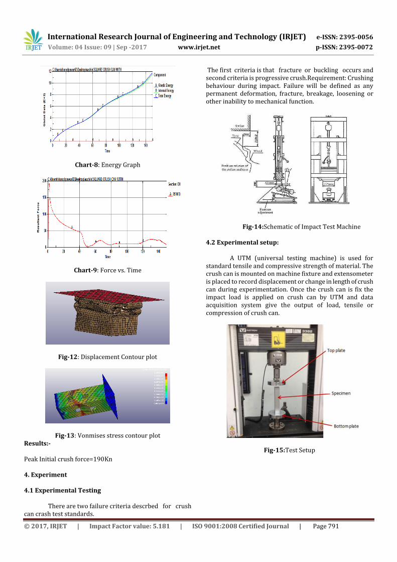
4.2 Experimental setup: A UTM (universal testing machine) is used for
standard tensile and compressive strength of material. The crush can is mounted on machine fixture and extensometer is placed to record displacement or change in length of crush can during experimentation. Once the crush can is fix the impact load is applied on crush can by UTM and data acquisition system give the output of load, tensile or compression of crush can.
Fig-15:Test Setup
International Research Journal of Engineering and Technology (IRJET) e-ISSN: 2395-0056
Volume: 04 Issue: 09 | Sep -2017 www.irjet.net p-ISSN: 2395-0072
© 2017, IRJET | Impact Factor value: 5.181 | ISO 9001:2008 Certified Journal | Page 792
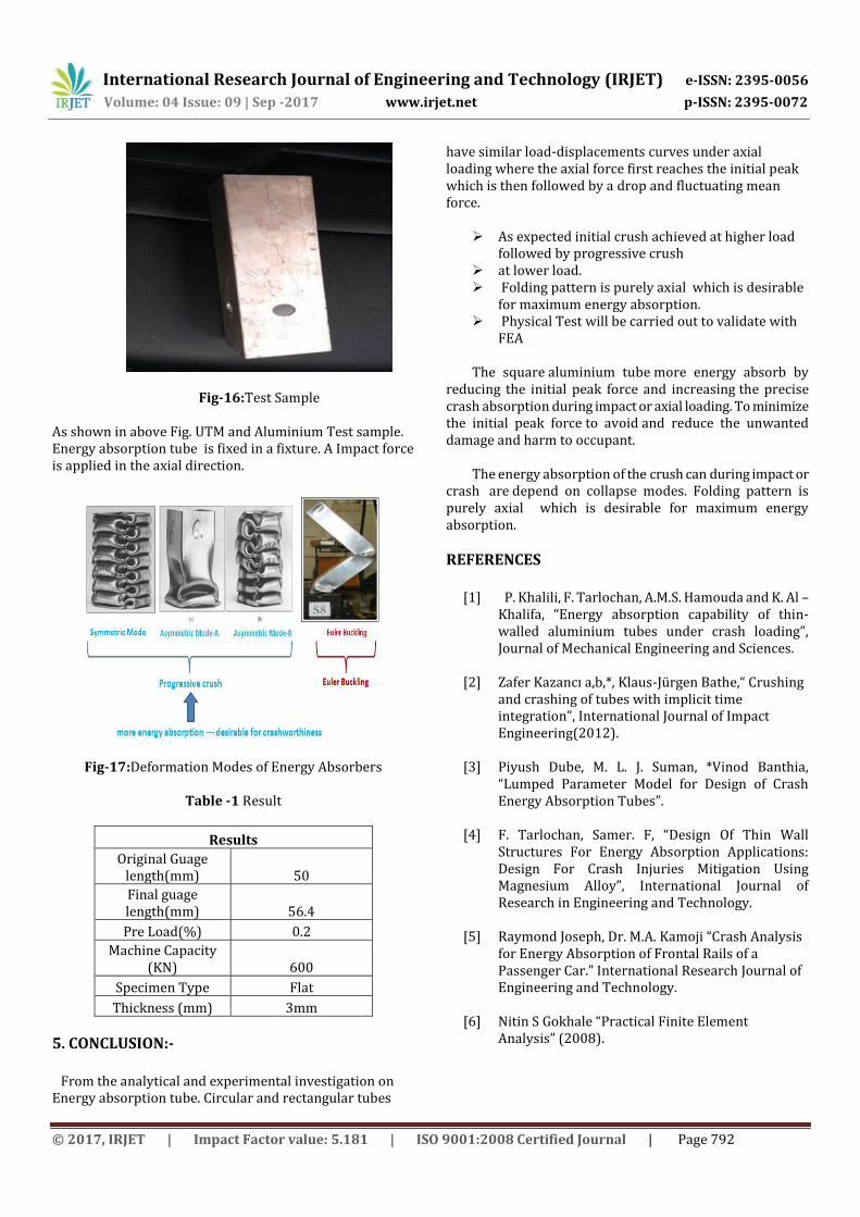
Fig-16:Test Sample As shown in above Fig. UTM and Aluminium Test sample. Energy absorption tube is fixed in a fixture. A Impact force is applied in the axial direction.
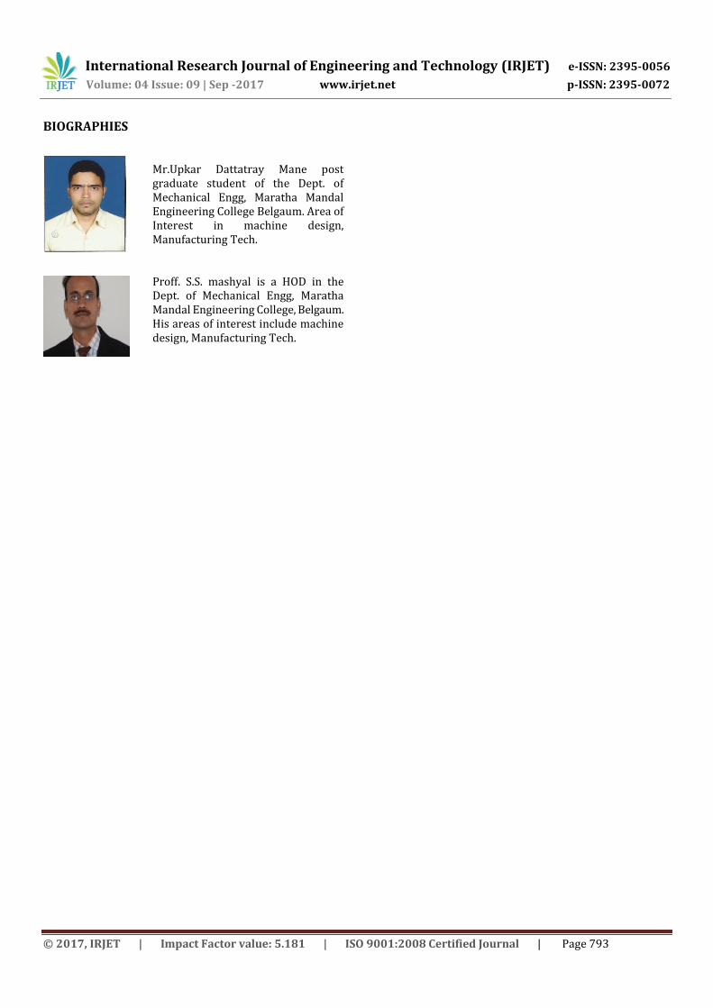
Fig-17:Deformation Modes of Energy Absorbers
Table -1 Result
Results
Original Guage length(mm) 50
Final guage length(mm) 56.4
Pre Load(%) 0.2
Machine Capacity (KN) 600
Specimen Type Flat
Thickness (mm) 3mm
5. CONCLUSION:- From the analytical and experimental investigation on Energy absorption tube. Circular and rectangular tubes
have similar load-displacements curves under axial loading where the axial force first reaches the initial peak which is then followed by a drop and fluctuating mean force.
As expected initial crush achieved at higher load followed by progressive crush
at lower load. Folding pattern is purely axial which is desirable
for maximum energy absorption. Physical Test will be carried out to validate with
FEA The square aluminium tube more energy absorb by
reducing the initial peak force and increasing the precise crash absorption during impact or axial loading. To minimize the initial peak force to avoid and reduce the unwanted damage and harm to occupant.
The energy absorption of the crush can during impact or
crash are depend on collapse modes. Folding pattern is purely axial which is desirable for maximum energy absorption.
REFERENCES
[1] P. Khalili, F. Tarlochan, A.M.S. Hamouda and K. Al – Khalifa, “Energy absorption capability of thin-walled aluminium tubes under crash loading”, Journal of Mechanical Engineering and Sciences.
[2] Zafer Kazancı a,b,*, Klaus-Jürgen Bathe,“ Crushing and crashing of tubes with implicit time integration”, International Journal of Impact Engineering(2012).
[3] Piyush Dube, M. L. J. Suman, *Vinod Banthia, “Lumped Parameter Model for Design of Crash Energy Absorption Tubes”.
[4] F. Tarlochan, Samer. F, “Design Of Thin Wall Structures For Energy Absorption Applications: Design For Crash Injuries Mitigation Using Magnesium Alloy”, International Journal of Research in Engineering and Technology.
[5] Raymond Joseph, Dr. M.A. Kamoji “Crash Analysis for Energy Absorption of Frontal Rails of a Passenger Car.” International Research Journal of Engineering and Technology.
[6] Nitin S Gokhale “Practical Finite Element Analysis” (2008).
International Research Journal of Engineering and Technology (IRJET) e-ISSN: 2395-0056
Volume: 04 Issue: 09 | Sep -2017 www.irjet.net p-ISSN: 2395-0072
© 2017, IRJET | Impact Factor value: 5.181 | ISO 9001:2008 Certified Journal | Page 793
BIOGRAPHIES
Mr.Upkar Dattatray Mane post graduate student of the Dept. of Mechanical Engg, Maratha Mandal Engineering College Belgaum. Area of Interest in machine design, Manufacturing Tech.
Proff. S.S. mashyal is a HOD in the Dept. of Mechanical Engg, Maratha Mandal Engineering College, Belgaum. His areas of interest include machine design, Manufacturing Tech.