analysis of diesel spray characteristic at high...
TRANSCRIPT
ANALYSIS OF DIESEL SPRAY CHARACTERISTIC AT HIGH PRESSURE
INJECTION
NORSYAMSUL SYAZWAN BIN MOHD NUJI
This thesis is submitted as partial fulfillment of the requirements for the award of the
Bachelor of Mechanical Engineering (Automotive)
Faculty of Mechanical Engineering
UNIVERSITI MALAYSIA PAHANG
JUNE 2012

vii
ABSTRACT
In diesel combustion, spray evaporation and mixture formation during ignition delay period play an important role in ignition, combustion and emission production. Spray evaporation begins immediately after start of fuel injection under the condition of high ambient temperature, in particular, at the middle of the spray. Spray atomization is fast promoted at this region, leading to ignition. The ambient temperature and injection pressures affect the droplets size and the number of droplets. In this project, the fuel will be injected at various injection parameters inside spray chamber in order to study the affect of that parameter towards spray characteristics. An analysis study was performed to investigate the macroscopic spray structure and the spray characteristics of high-pressure injector for the diesel engine. The spray structure and microscopic characteristics of high-pressure diesel injector were investigated when fuel was injected at various injection pressures and different nozzle diameter. Spray developing process, spray cone angle and spray tip penetration were obtained by using the software simulation of ANSYS-FLUENT, and the quantitative result of spray characteristics will be analyzes.

viii
ABSTRAK
Dalam pembakaran diesel, penyejatan semburan dan pembentukan campuran dalam tempoh lengah memainkan peranan yang penting dalam sistem pencucuhan, pembakaran dan pelepasan. Penyejatan semburan bermula serta-merta selepas permulaan suntikan bahan api di bawah keadaan suhu ambien yang tinggi, khususnya, pada pertengahan semburan. Pengabusan semburan terjadi di rantau ini, yang membawa kepada penyalaan. Suhu ambien dan tekanan suntikan mempengaruhi saiz titisan dan bilangan titisan.Dalam projek ini, bahan api akan disuntik pada pelbagai parameter suntikan di dalam kebuk semburan untuk mengkaji kesan parameter tersebut terhadap ciri-ciri semburan. Satu kajian analisis telah dilakukan untuk menyiasat struktur semburan makroskopik dan ciri-ciri semburan suntikan pada tekanan yang tinggi untuk enjin diesel. Struktur semburan dan ciri-ciri mikroskopik pada tekanan tinggi suntikan diesel telah disiasat apabila bahan api disuntik pada pelbagai tekanan suntikan dan muncung diameter yang berbeza . Proses membangunkan semburan, sudut kon semburan dan panjang semburan telah diperolehi dengan menggunakan perisian simulasi ANSYS-FLUENT, dan keputusan ciri-ciri semburan yang pelbagai akan di analisis.
ix
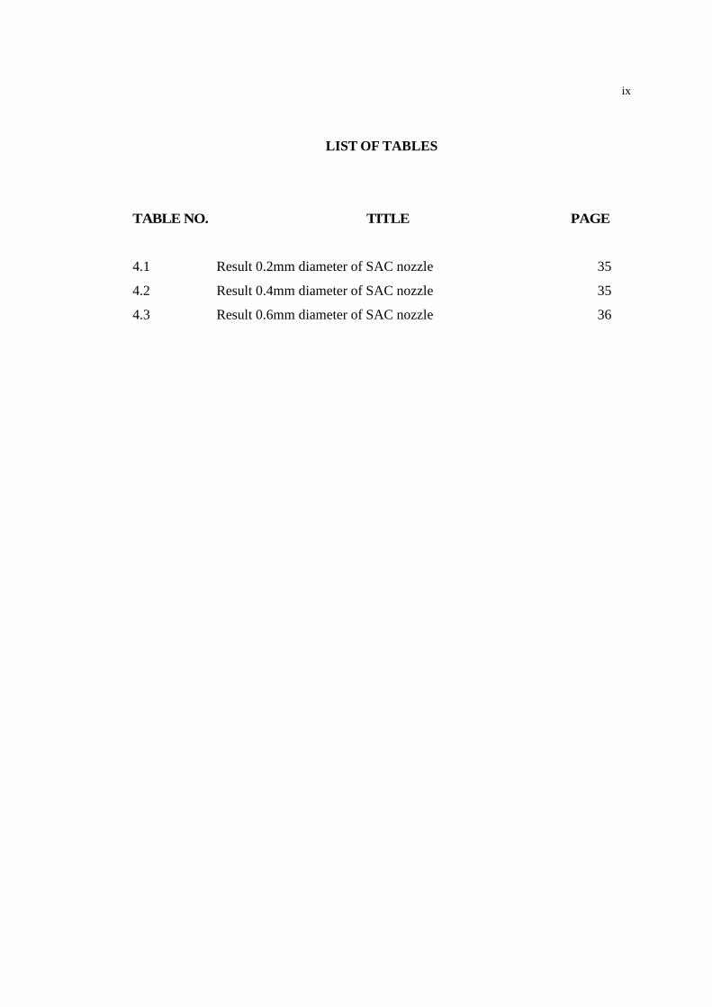
LIST OF TABLES
TABLE NO. TITLE PAGE
4.1 Result 0.2mm diameter of SAC nozzle 35
4.2 Result 0.4mm diameter of SAC nozzle 35
4.3 Result 0.6mm diameter of SAC nozzle 36
x
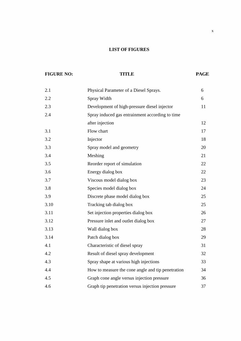
LIST OF FIGURES
FIGURE NO: TITLE PAGE
2.1 Physical Parameter of a Diesel Sprays. 6
2.2 Spray Width 6
2.3 Development of high-pressure diesel injector 11
2.4 Spray induced gas entrainment according to time
after injection 12
3.1 Flow chart 17
3.2 Injector 18
3.3 Spray model and geometry 20
3.4 Meshing 21
3.5 Reorder report of simulation 22
3.6 Energy dialog box 22
3.7 Viscous model dialog box 23
3.8 Species model dialog box 24
3.9 Discrete phase model dialog box 25
3.10 Tracking tab dialog box 25
3.11 Set injection properties dialog box 26
3.12 Pressure inlet and outlet dialog box 27
3.13 Wall dialog box 28
3.14 Patch dialog box 29
4.1 Characteristic of diesel spray 31
4.2 Result of diesel spray development 32
4.3 Spray shape at various high injections 33
4.4 How to measure the cone angle and tip penetration 34
4.5 Graph cone angle versus injection pressure 36
4.6 Graph tip penetration versus injection pressure 37
xi
TABLE OF CONTENTS
TITLE PAGE
PAGE
FRONT PAGE i
DECLARATION
DEDICATION
ACKNOWLEDGEMENT
ABSTRACT
ABSTRAK
LIST OF TABLES
LIST OF FIGURES
ii
v
vi
vii
viii
ix
x
CHAPTER 1 INTRODUCTION 1
1.1 Introduction 1
1.2 Project Background 1
1.3 Problem Statement 2
1.4 Objective 3
1.5 Scopes of work 3
CHAPTER 2 LITERATURE REVIEW 4
2.1 Introduction 4
2.2 Spray Characteristics 6
2.3 Fuel Injection System 7
2.4 Spray Penetration 7
2.5 Spray Cone Angle 8

xii
2.6 Droplet Size Distribution
2.7 Break up Length
2.8 Evolution Processes of Global Spray
2.9 Spray Simulation
2.10 Software Simulation
2.11 Computational Fluid Dynamic (CFD)
9
10
10
12
13
14
CHAPTER 3 METHODOLOGY 16
3.1 Introduction 16
3.2 Flow Chart of Methodology 16
3.2.1 Simulation 16
3.3 Injector
3.4 Steps of Simulation
18
19
3.4.1 Geometry 3.4.2 Meshing
3.4.3 Setup
19 20 21
CHAPTER 4 RESULT AND DISCUSSION 30
4.1 Introduction 30
4.2 Results 30
4.2.1 Spray Characteristics 31 4.2.2 Spray Developments 32 4.2.3 Spray Shape at Various High Injection 33 4.2.4 How to Measure the Result 34 4.2.5 Table of Result 35 4.2.6 Graph of Result
36
xiii
CHAPTER 5 CONCLUSION AND RECOMMENDATION 38
5.1 Summary of The Project 38
5.2 Conclusions of The Project 38
5.3 Recommendations 39
5.4 Future Work 39
REFERENCES
40
APPENDICES 41
Appendix A Gantt Chart(Project Schedules of PSM 1 and PSM 2) 41

CHAPTER 1
INTRODUCTION
1.1 INTRODUCTION
In the diesel engine, combustion and emission characteristics are influenced by
fuel atomization, nozzle geometry, injection pressure, shape of inlet port, and other
factors. In order to improve fuel–air mixing, it is important to understand the fuel
atomization and spray formation processes. So far, to improve the combustion
performance and particulate emissions, many researchers have investigated the
characteristics of the spray behavior and structure for the high-pressure injector by
experimental and theoretical approaches. However, many studies about the detailed
information of atomization characteristics and spray developing process of high-
pressure diesel spray were still needed.
1.2 PROJECT BACKGROUND
In diesel combustion, spray evaporation and mixture formation during ignition
delay period play an important role in ignition, combustion and emission production.
Spray evaporation begins immediately after start of fuel injection under the condition of
high ambient temperature, in particular, at the middle of the spray. Spray atomization is
fast promoted at this region, leading to ignition. The ambient temperature and injection
pressures affect the droplets size and the number of droplets. In this project, the fuel will
be injected at various injection parameters inside spray chamber order to study the
affect of that parameter towards spray characteristics. Accurate control of diesel spray
parameters (timing, delivery, flow rate, pressure, spray geometry, so on.) is the most

2
effective means to influence fuel and air mixing and to achieve both clean burning and
high efficiency. The ANSYS –FLUENT software has been used to investigate the spray
characteristic development after injection with various high pressures.
The impingement of diesel spray onto interposed surfaces in an IC engine,
equipped either with a direct or an indirect injection system, is a fundamental issue
affecting mixture preparation prior to combustion and, therefore, also affecting engine
performance and pollutant emissions. In this context, the development of diesel spray
systems relies on accurate knowledge of the fluid dynamic and thermal processes
occurring during spray. Injection systems however, are very complex and the
background physics requires fundamental studies, performed at simplified flow
geometries. In particular, the impact of individual droplets and spray characteristic has
been extensively used to describe the behavior of spray impact and to predict its
outcome, despite the known fact that a spray does not behave exactly as a summation of
individual droplets; then, researchers incorporate all the governing parameters. The
present paper offers a critical review of the investigations reported in the literature on
spray-wall impact relevant to IC engines, in an attempt to address the rationale of
describing spray-wall interactions based on the knowledge of single droplet impacts.
Moreover, although the review was first aimed at fuel-spray impingement in IC engines,
it also became relevant to provide a systematization of the current state of the art, which
can be useful to the scientific community involved with droplet and spray impingement
phenomena.
1.3 PROBLEM STATEMENT
Researchers are exploring ways to reduce pollution formation in the engine by
using clean combustion strategies. In the diesel engine, combustion and emission
characteristics are influenced by fuel atomization, nozzle geometry, injection pressure,
shape of inlet port, and other factors. In order to improve fuel–air mixing, it is important
to understand the fuel atomization and spray formation processes. The ANSYS –
FLUENT software has been used to investigate the spray characteristic development.

3
1.4 OBJECTIVES
The objectives of this project are:
(i) To investigate the tip penetration of spray at various injection parameters
and different diameter of SAC nozzle.
(ii) To investigate the cone angle of spray at various injection parameters
and different diameter of SAC nozzle.
(iii) To investigate the spray developments
1.5 SCOPES OF WORK
The scopes of the study are:
(i) Measurement of diesel spray cone angle at various parameters.
(ii) Comparison and measurement of spray penetration length at various
parameters.
(iii) Comparison of spray geometry including the development of liquid
phase and vapor phase area.
4
CHAPTER 2
LITERATURE REVIEW
2.1 INTRODUCTION
The literature review had been carry out with reference from sources such as
journal, books, thesis and internet in order to gather all information related to the title of
this project. This chapter covers about the previous experiment doing by researcher and
to go through the result by experimental and numerical. Today, adoption of diesels in
the world would decrease the nation’s petroleum consumption. However, diesels emit
much higher levels of pollutants, especially particulate matter and NOx (nitrogen
oxides). These emissions have prevented more manufacturers from introducing diesel
passenger cars.
Researchers are exploring ways to reduce pollution formation in the engine by
using clean combustion strategies. A key component to the development of clean
combustion is controlling the fuel spray and fuel/air mixing. In the diesel engine,
combustion and emission characteristics are influenced by fuel atomization, nozzle
geometry, injection pressure, shape of inlet port, and other factors. In order to improve
fuel–air mixing, it is important to understand the fuel atomization and spray formation
processes. So far, to improve the combustion performance and particulate emissions,
many researchers have investigated the characteristics of the spray behavior and
structure for the high-pressure injector by experimental and theoretical approaches.
However, many studies about the detailed information of atomization characteristics
and spray developing process of high-pressure diesel spray were still needed.

5
Spray structure and atomization characteristics of diesel spray have been
investigated by Dennis (1998), Maruyama (2001), Ishikawa (1996), Nimura (1996) and
Farrell(1996). They reported that the characteristics of fuel spray for the fuel injector
obtained by using the shadowgraphs and particle image velocimetry at various chamber
conditions. Yeom (2001) and Su (1996) compared experimental results with numerical
ones about spray shapes, axial mean velocity, and mean droplet diameter. In original
KIVA code, the breakup of droplet is calculated with the Taylor analogy breakup (TAB)
model. In order to improve the calculation accuracy, the breakup model of injection
spray is modified by introducing Kelvin–Helmholtz and Rayleigh–Taylor (KH–RT)
model used by Su and Beale and Reitz .In spite of these studies, it is still needed to
improve the breakup model and verify the predicted results. The objective of this work
is to investigate the effect of injection pressure and temperature ambient on the
macroscopic spray behavior and atomization characteristics of high-pressure spray the
common rail type diesel injection system. The test fuel used in this experiment was
diesel fuel with the density of 880 kg/m3 and kinematic viscosity of 2.5 x 10⁻⁶ m2/s. The
injection pressures selected here were 60, 70, and 80 MPa. Ambient conditions were
atmospheric pressure and room temperature for all the test cases. The nozzle hole
diameter was 0.3 mm and the depth was 0.8 mm, which makes the nozzle L/D ratio
about 2.67 according to Chang Sik Lee and Sung Wook Park,(2002).
In this study, the fuel will be injected at various injection parameters inside
spray chamber in order to study the affect of that parameter towards spray
characteristics. Macroscopic behaviors of the fuel spray such as process of spray
development, spray penetration and spray cone angle were taken in the conditions at
various injection pressures. Accurate control of diesel spray parameters (timing,
delivery, flow rate, pressure, spray geometry, so on.) is the most effective means to
influence fuel and air mixing and to achieve both clean burning and high efficiency.
6
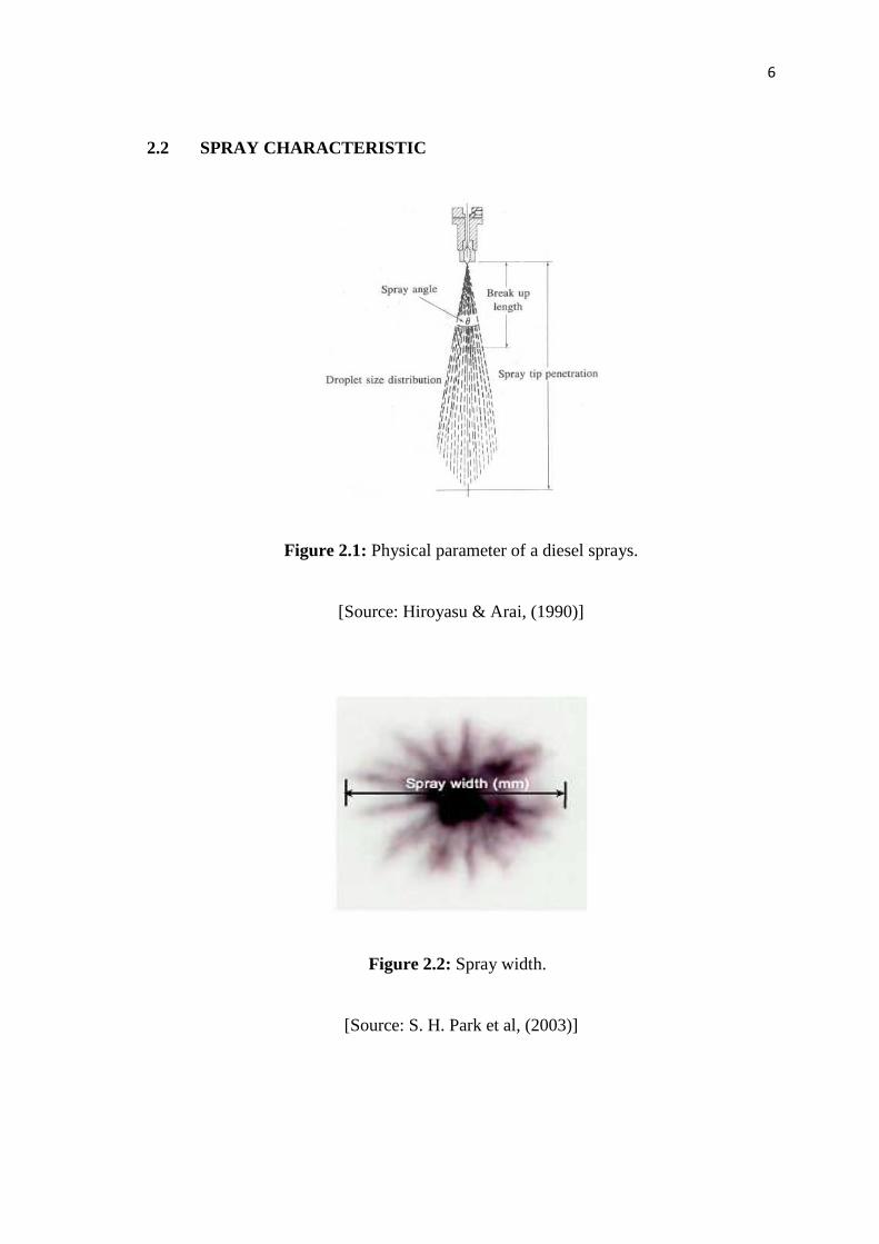
2.2 SPRAY CHARACTERISTIC
Figure 2.1: Physical parameter of a diesel sprays.
[Source: Hiroyasu & Arai, (1990)]
Figure 2.2: Spray width.
[Source: S. H. Park et al, (2003)]

7
2.3 FUEL INJECTION SYSTEM
The fuel injection system needs to provide different operating modes for the
different loads. Fuel injection pressure is very high. These higher pressure values allow
a higher penetration and reduce the mean droplet diameter determining a better
atomized spray and a good penetration. Too high injection pressures will enhance
atomization but at the same time produce an over penetrating sprays and wall wetting
problems, especially when a sac volume is present. For the unthrottled part-load case, a
late injection is needed in order to allow stratified charge combustion, with a well
atomized compact spray to control the stratification. A well dispersed spray is desirable,
with bigger cone angle and a conical shape. As mentioned before the higher injection
pressure is necessary to reduce the Sauter mean diameter (SMD) of the liquid spray. To
better characterize the spray size distribution the DV90 statistic may also be introduced,
which is a quantitative measure of the largest droplets in the spray. It is the droplet
diameter corresponding to the 90% volume point, so it gives a measure of the droplet
size distribution spread. GDI injectors can either be single fluid or air-assisted (two
phase) and may be classified by atomization mechanism (sheet, turbulence, pressure,
cavitations), by actuation type, nozzle configuration (that can be either swirl, slit,
multihole or cavity type), or by spray configuration (hollow cone, solid-cone, fan, multi-
plume).Rossella Rotondi and Gino Bella,( 2005).
2.4 SPRAY PENETRATION
The spray penetration is defined as the maximum distance from the nozzle to the
tip of the spray at any given time and is one of the most important characteristics of the
combustion process as shown in Figure 2.1. If the spray penetration is too long, there is
a risk of impingement on the wall of the combustion chamber, which may lead to fuel
wastage and the formation of soot. This normally occurs when the chamber wall is cold
and where there is limited air motion. However, a short penetration will reduce mixing
efficiency hence resulting in poor combustion. Hence the information of spray tip
penetration would be useful for the design of the engine combustion chamber. The

8
dependence of penetration on injection parameters differed significantly from one
investigation to another.
Increasing the ambient pressure was shown to decrease the spray tip penetration
as well as the break-up length. Changing the ambient temperature had a minor effect on
the spray tip penetration, due to a corresponding reduction in ambient density. However,
a reduction in the spray angle was observed at higher temperatures, suggesting that the
evaporation of the droplets were confined to the region on the periphery of the spray.
Hiroyasu and Arai (1990).
The effects of ambient gas density and fuel vaporization on spray penetration
were examined by Naber and Siebers (1996). The sprays were generated with an
electronically controlled, common-rail, single-hole injector. The injection pressure was
137 MPa and the diameter of the nozzle hole was 0.257 mm. A high-speed camera was
used to record the behavior of the sprays in a constant-volume combustion chamber.
The ambient density was varied between 3 and 200 kg m-3. The most noticeable trends
are the decrease in penetration with an increase in ambient density and the decreasing
rate of penetration with time. The effect of vaporization was to reduce the penetration.
The reduction is as much as 20% at the low density conditions. The effects of
vaporization became smaller for longer penetration distance and high gas density.
2.5 SPRAY CONE ANGLE
The spray cone angle from Figure 2.1 is defined as the angle formed by two
straight lines drawn from the injector tip to the outer periphery of the spray Hiroyasu &
Arai, (1990), Lefebvre (1989). According to Naber and Siebers (1996), the definition of
the spray angle and the spray penetration are dependent on each other.
The spray cone angle is a qualitative indicator of how well the spray disperses. It
is influenced by the nozzle dimensions, the liquid properties and the density of the
medium in which the spray is introduced. The influence of the nozzle aspect ratio (L/D)
on the spray angle was examined by several researchers. Shimizu (1984) showed that an

9
L/D of approximately 4 or 5 gave the maximum cone angle and shortest break-up length
and also that an increase and decrease of L/D gave respectively a smaller cone angle
and longer break-up length. The effects of kinematic viscosity and injection pressure on
the spray cone angle were examined by Hiroyasu (1990). They found that spray angles
were widened by a reduction in liquid viscosity and an increase in injection pressure,
before stabilizing after reaching a maximum value. The increasing of cone angle will be
effect the width of spray. From Figure 2.2 the width of spray is measured at horizontal
spray by looks below the spray images or chamber at maximum width or distribution of
spray. The spray width defines how well the spray disperses. S. H. Park et al, (2003).
2.6 DROPLET SIZE DISTRIBUTION
From Figure 2.1 the droplet size distribution (DSD) in sprays is the crucial
parameter needed for the fundamental analysis of the transport of mass, momentum and
heat in engineering systems. However, the DSD determines the quality of the spray and
consequently influences to a significant extent the processes of fouling and undesired
emissions in combustion Hiroyasu and Arai (1990). The diameter of the droplets
obtained as a result of atomization is based on a series of parameters as follows:
(i) Rate of injection: the diameter of the droplet increases with the rate of
injection as an increase in the volume of the injected liquid produces a
greater drag of the working fluid, the aerodynamic interaction grows and
the critical size of the droplets increases. Apart from this, increasing the
numeric population of droplets intensifies de coalescence, resulting in a
growth in the geometry of the droplets.
(ii) Density ratio (ρ*): the relation of densities has two opposing effects on
the size of the droplets, intensification of atomization and the possibility
that there will be coalescence. On increasing the relationship of densities
a greater aerodynamic interaction exists, which causes the droplets to
slow down and an increase in the numerical population in their field.

10
(iii) Working fluid temperature (Tg): on increasing working fuel temperature
there is an increase on the rate of evaporation, due to which at the
beginning of this the droplets with small diameters tend to evaporate
completely while those droplets with greater diameters maintain a stable
geometry until they evaporate completely.
(iv) Evolution of the diameter of droplets during time: It’s generally
considered that the medium diameter of the droplets decreases at the
point of the spray and increases at the tail, while in areas distant from the
injector they maintain a rate of constant values. Generally speaking, the
sizes of the droplets tend to diminish at the beginning of the injection and
grow at the end. Fausto A. Sánchez-Cruz et al, (2005).
2.7 BREAK UP LENGTH
The break up length of the spray as shown in Figure 2.1 is a very important
characteristic to define the behavior of the spray in the combustion chamber. This zone
of the spray is also called continuous or stationary and it is understood as being from the
nozzle exit to the point where the separations of the first droplets occur. To define this
zone the use of diverse measurements methods and techniques is of vital importance. In
the literature we find some of the most useful measurement methods and techniques in
the analysis of the break up length, Hiroyasu & Arai, (1990), Arai et al., (1984)
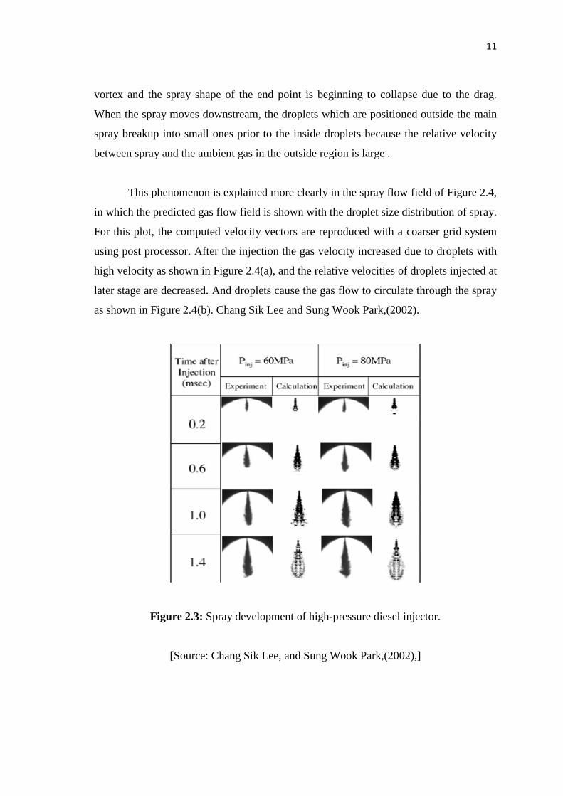
2.8 EVOLUTION PROCESSES OF GLOBAL SPRAY
Figure 2.3 shows the comparison between experimental results and predicted
results of developing processes of global sprays with different injection pressure. The
computed two-dimensional slice images are also shown in this figure, and a reasonable
agreement between photographs and calculations is obtained. It is observed that the
droplets near the main spray are dispersed more rapidly with the increase of injection
pressure. At the beginning stage, the main stream of the spray shaped like a spiral
11
vortex and the spray shape of the end point is beginning to collapse due to the drag.
When the spray moves downstream, the droplets which are positioned outside the main
spray breakup into small ones prior to the inside droplets because the relative velocity
between spray and the ambient gas in the outside region is large .
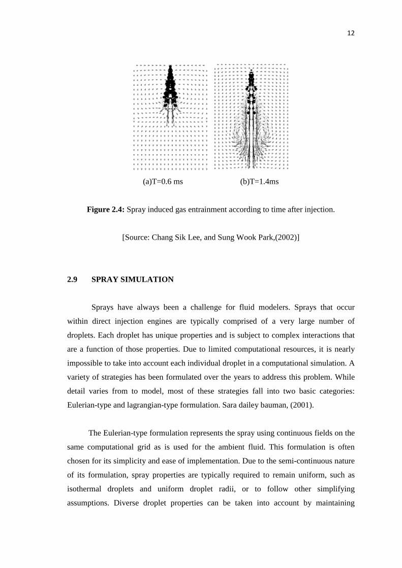
This phenomenon is explained more clearly in the spray flow field of Figure 2.4,
in which the predicted gas flow field is shown with the droplet size distribution of spray.
For this plot, the computed velocity vectors are reproduced with a coarser grid system
using post processor. After the injection the gas velocity increased due to droplets with
high velocity as shown in Figure 2.4(a), and the relative velocities of droplets injected at
later stage are decreased. And droplets cause the gas flow to circulate through the spray
as shown in Figure 2.4(b). Chang Sik Lee and Sung Wook Park,(2002).
Figure 2.3: Spray development of high-pressure diesel injector.
[Source: Chang Sik Lee, and Sung Wook Park,(2002),]
12
(a)T=0.6 ms (b)T=1.4ms
Figure 2.4: Spray induced gas entrainment according to time after injection.
[Source: Chang Sik Lee, and Sung Wook Park,(2002)]
2.9 SPRAY SIMULATION
Sprays have always been a challenge for fluid modelers. Sprays that occur
within direct injection engines are typically comprised of a very large number of
droplets. Each droplet has unique properties and is subject to complex interactions that
are a function of those properties. Due to limited computational resources, it is nearly
impossible to take into account each individual droplet in a computational simulation. A
variety of strategies has been formulated over the years to address this problem. While
detail varies from to model, most of these strategies fall into two basic categories:
Eulerian-type and lagrangian-type formulation. Sara dailey bauman, (2001).
The Eulerian-type formulation represents the spray using continuous fields on the
same computational grid as is used for the ambient fluid. This formulation is often
chosen for its simplicity and ease of implementation. Due to the semi-continuous nature
of its formulation, spray properties are typically required to remain uniform, such as
isothermal droplets and uniform droplet radii, or to follow other simplifying
assumptions. Diverse droplet properties can be taken into account by maintaining

13
multiple fields and transport equations. This type is almost appropriate when concerned
about macroscopic behavior of the spray on scales much larger than the average droplet
spacing or on scales on the order of the spray penetration length. However, the Eulerian
approach suffers from numerical diffusion, particularly on coarse grids. Sara dailey
bauman, (2001).
The lagrangian-type formulation is based on a fluid-particle model introduced by
Dukowicz. The spray is represented by a collection of computational particles. Each
particle in turn represents a parcel of spray droplets that are assumed to have identical
properties such as position, velocity, density, radius, and temperature. Often referred to
as the discrete droplet model or stochastic particle model, this formulation is more
resistant to the numerical diffusion inherent in a semi-continuous field representation. If
appropriately chosen probability distributions are used to define particle properties, an
adequate statistical representation of realistic sprays may be obtained when a
sufficiently large number of computational particles are used. In the limit of single
droplet per particle and assuming appropriate initial conditions are known, this type of
formulation approaches the ideal conditions for simulating the spray. Sara dailey
bauman, (2001).
2.10 SOFTWARE SIMULATION
Nowadays computational fluid dynamics (CFD) plays a key role for the
optimization of the combustion process in direct injection (DI) diesel engines. Despite
their great uncertainties compared to the experimental studies, numerical simulations
permit carrying out extensive parametric studies, isolating every single variable
involved in the general process at any point in time and at any position in physical
space. Modeling also allows one to artificially separate specific sub process in example
spray atomization, evaporation, diffusive combustion, and emissions from the others
that would interact in the real system or to investigate the effects of unnatural boundary
conditions on such processes, in order to better understand the combustion process in
engines. Basically, engine simulation models can be classified into three categories,
depending on their complexity and increasing requirements with respect to the
14
computational power: thermodynamics and phenomenological models, and the
multidimensional models used in the so-called CFD codes. ANSYS CFD (FLUENT) is
a commercially available 2D-3D computational fluid dynamics (CFD) code. J. M.
Desantes et al, (2009).
The thermodynamic codes assume that the cylinder charge is uniform in both
composition and temperature, at all times during the cycle. These models are
computationally very efficient but cannot provide insight into local processes such as
the spatial variation in mixture composition and temperature, essential to predict
exhaust emissions. Phenomenological spray and combustion models are more complex
than the thermodynamic models since they divide the combustion chamber into
numerous different zones, characterized by different temperature and compositions. In
the multidimensional CFD-codes the full set of differential equations for species, mass,
energy, and momentum conservation are solved on a relatively fine numerical mesh
with the inclusion of models to account for the effects of turbulence. As a result, these
models are best suited to analyze the various subscale processes of mixture formation
and combustion with great detail. J. M. Desantes et al, (2009).
2.11 COMPUTATIONAL FLUID DYNAMIC (CFD)
Computational Fluid Dynamics or CFD is the analysis of systems involving
fluid flow, heat transfer and associated phenomena such as chemical reactions by means
of computer based simulations. Computational Fluid Dynamics is basically a tool in the
form of a software package which treats the fluid as being broken up into small
volumes, and applies a suitable algorithm to solve the Navier Stokes equations of flow
motion. Versteeg and Malasekera,( 1995) Computational Fluid Dynamics (CFD) itself
emerged as a tool to cut cost and time by doing away with costly experiments to
produce better, more efficient engineering designs. In practise, some experimental data
or theoretical calculations will still be needed to verify at least the unit or benchmark
case, and possibly if time and money permits the final design as well. Experimental data
is also often needed for input in CFD simulations, for example in setting the boundary
conditions of the model. Theoretical calculations based on simple models are always

15
useful, providing back-of-the-envelope estimates for boundary conditions and
sometimes results expected. This shows that an engineer will never do away with
experiments and theoretical calculations and totally depend on simulations .Anderson
(1995).
This study utilizes a commercial CFD package, FLUENT v6.1.22, which solves
conservation equations for mass and momentum. Since the flow involved is gaseous and
fuel at a high enough pressure to cause appreciable density change and shock waves,
additional equations for energy conservation (using ideal gas) and also species
conservation are solved. The species conservation equation is used to represent the
different chemical components involved, namely methane, representing the CNG fuel
and the surrounding air into which the fuel is injected. Additionally, transport equations
are also solved since the flow is turbulent. All the governing equations used are listed in
the following section. For all flows; FLUENT solves conservation equations for mass
and momentum. For flows involving heat transfer or compressibility, an additional
equation for energy conservation is solved. For flows involving species mixing or
reactions, a species conservation equation is solved or, if the non-premixed combustion
model is used, conservation equations for the mixture fraction and its variance are
solved. Additional transport equations are also solved when the flow is turbulent.

16
CHAPTER 3
METHODOLOGY
3.1 INTRODUCTION
The methodology had been done right after the motivation and objectives of the
project were identified. This methodology functioned as guidance in order to complete
the project given. The completed structure of methodology had been illustrated and
planned as guideline to achieve the objectives of the project. Computational Fluid
Dynamics or CFD is the analysis of systems involving fluid flow, heat transfer and
associated phenomena such as chemical reactions by means of computer based
simulations.
3.2 FLOW CHART OF METHODOLOGY
3.2.1 Simulation
Figure 3.1 shows the flow chart of the project. The project starts with literature
review and research about title. These is consisting a review of the concept spray
process, fuel properties, injection characteristics, software used, and spray modeling.
These tasks have been done through research on the book, journal, technical repot and
others sources.