analysis of damping materials in a transmission line loudspeaker system loudspeaker … ·...
TRANSCRIPT

119
27–29th September, 2012, Łódź, Poland
new trends in audio and video / signal processing algorithms, architectures, arrangements and applications
ntav/spa 2012
Analysis of Damping Materialsin a Transmission Line Loudspeaker System
Krzysztof Lusztak B.Sc. Lodz University of Technology
Lodz, Poland [email protected]
Abstract — The presented paper contains an analysis of the influ-ence of various types of damping material in a transmission line loudspeaker enclosure on the acoustic emission spectrum. Damp-ing of the tunnel is crucial in the design of this type of enclosures. Six types of materials traditionally used in home speaker construc-tion were studied.
Keywords — loudspeaker, vented enclosure, bass-reflex, sealed en-closure, transmission line, waveguide, damping materials, felt, wool, foam.
Analysis of damping materials in a transmission line loudspeaker system
Krzysztof LUSZTAK B.Sc. Lodz University of Technology
Lodz, Poland [email protected]
Michał BUJACZ Ph.D. Lodz University of Technology
Lodz, Poland [email protected]
Abstract— The presented paper contains an analysis of the influence of various types of damping material in a transmission line loudspeaker enclosure on the acoustic emission spectrum. Damping of the tunnel is crucial in the design of this type of enclosures. Six types of materials traditionally used in home speaker construction were studied.
Keywords- loudspeaker, vented enclosure, bass-reflex, sealed enclosure, transmission line, waveguide, damping materials, felt, wool, foam.
I. INTRODUCTION The most common loudspeaker enclosure types are either
closed [1] or vented (bass-reflex type) [2,3]. These two types of enclosures can be relatively easily and accurately modeled, allowing mathematical simulations to be used in efficient design Moreover, because of the small number of variables, the enclosures can also be quickly tested through trial and error with very good effect. For the sealed enclosure only the volume of the loudspeaker and the amount and type of damping materials can be changed, while the bass reflex enclosure (utilizing the Helmholtz resonator) introduces two more variables - the length and the diameter of the resonator (which are in fact correlated [3]). Thanks to these features the closed and bass-reflex enclosures have dominated the market and nearly forced out all other enclosures types from commercial domestic applications. Due to the stretching of the speaker response toward the low frequencies with relatively low design effort, the bass reflex enclosure are the predominant type used in home audio. The trend is so strong that many transducers are designed specifically for use in bass reflex enclosures.
However, these types of enclosures have several disadvantages. The resonant frequency of a loudspeaker mounted in a sealed enclosure increases, but at the same time begins to fall earlier near the low frequencies, which may result in the listener perceiving a lack of low-frequency sound material. The bass reflex type enclosure introduces a delay into the played sound – due to the fact that within the range of frequencies near the tuning frequency of the resonator it is the resonator itself (not the loudspeaker) that is the source of the sound. The bass reflex enclosure also increases the risk of overdriving the speaker at frequencies below tuning, especially if it is poorly designed.
There is a loudspeaker enclosure type that avoids the aforementioned problems – the transmission line enclosure [4,5]. This type of enclosure contains a tunnel behind the loudspeaker, with specific parameters serving as a waveguide. The resonance phenomena doesn't appear in transmission line enclosure, so there is no audible lag in the music material [6]. The response of the speaker has a natural decrease of 12dB/octave in the direction of the low frequencies and this decline begins later than in closed speaker casings. The waveguide is designed to use the rear surface of the speaker membrane, reverse it in phase and use as a second source of sound. Unfortunately, this type of enclosure is difficult to design. The number of variables is very large: the length of the tunnel, the location of the speaker relative to the entry of the tunnel, the tunnel’s capacity, the cross sectional area of the beginning and end of the tunnel, and their relationship to each other, the type and location of the damping material, the number of turns in the tunnel. Most of these variables can be simulated by using appropriate modeling software. Unfortunately it is impossible to properly simulate the placement and the type of damping material, which is crucial in this type of construction. To understand why the damping is crucial it is necessary to first have a good grasp of the principle of operation of a transmission line enclosure.
II. THEORY BEHIND TRANSMISSION LINE ENCLOSURES. The basic principle of a transmission line enclosure is that
the wave emitted from the front of the speaker membrane is combined with the wave from the rear of the membrane after it has traveled the transmission line tunnel and has shifted in phase. The shift depends on the length of the tunnel and the wavelength of the sound. To reverse the phase by 180 degrees (to provide the same phase of the emission front side of the membrane and end of the tunnel) at a frequency of 30Hz the tunnel would need to be half as long as the wavelength of that frequency, i.e. approximately 5.7m (assuming sound speed of 344m/s). In practice, such a long tunnel is not necessary. The vector arithmetic shows that even when the phase is shifted by about 90 (with the length of the tunnel equal to ¼ wavelength) the summary emission is greater than the emission of only the front side of the membrane (Figure 1). So for a “resonance” at 30Hz the tunnel length only needs to be about 2.9m.
Michał Bujacz Ph.D. Lodz University of Technology
Lodz, Poland [email protected]
Analysis of damping materials in a transmission line loudspeaker system
Krzysztof LUSZTAK B.Sc. Lodz University of Technology
Lodz, Poland [email protected]
Michał BUJACZ Ph.D. Lodz University of Technology
Lodz, Poland [email protected]
Abstract— The presented paper contains an analysis of the influence of various types of damping material in a transmission line loudspeaker enclosure on the acoustic emission spectrum. Damping of the tunnel is crucial in the design of this type of enclosures. Six types of materials traditionally used in home speaker construction were studied.
Keywords- loudspeaker, vented enclosure, bass-reflex, sealed enclosure, transmission line, waveguide, damping materials, felt, wool, foam.
I. INTRODUCTION The most common loudspeaker enclosure types are either
closed [1] or vented (bass-reflex type) [2,3]. These two types of enclosures can be relatively easily and accurately modeled, allowing mathematical simulations to be used in efficient design Moreover, because of the small number of variables, the enclosures can also be quickly tested through trial and error with very good effect. For the sealed enclosure only the volume of the loudspeaker and the amount and type of damping materials can be changed, while the bass reflex enclosure (utilizing the Helmholtz resonator) introduces two more variables - the length and the diameter of the resonator (which are in fact correlated [3]). Thanks to these features the closed and bass-reflex enclosures have dominated the market and nearly forced out all other enclosures types from commercial domestic applications. Due to the stretching of the speaker response toward the low frequencies with relatively low design effort, the bass reflex enclosure are the predominant type used in home audio. The trend is so strong that many transducers are designed specifically for use in bass reflex enclosures.
However, these types of enclosures have several disadvantages. The resonant frequency of a loudspeaker mounted in a sealed enclosure increases, but at the same time begins to fall earlier near the low frequencies, which may result in the listener perceiving a lack of low-frequency sound material. The bass reflex type enclosure introduces a delay into the played sound – due to the fact that within the range of frequencies near the tuning frequency of the resonator it is the resonator itself (not the loudspeaker) that is the source of the sound. The bass reflex enclosure also increases the risk of overdriving the speaker at frequencies below tuning, especially if it is poorly designed.
There is a loudspeaker enclosure type that avoids the aforementioned problems – the transmission line enclosure [4,5]. This type of enclosure contains a tunnel behind the loudspeaker, with specific parameters serving as a waveguide. The resonance phenomena doesn't appear in transmission line enclosure, so there is no audible lag in the music material [6]. The response of the speaker has a natural decrease of 12dB/octave in the direction of the low frequencies and this decline begins later than in closed speaker casings. The waveguide is designed to use the rear surface of the speaker membrane, reverse it in phase and use as a second source of sound. Unfortunately, this type of enclosure is difficult to design. The number of variables is very large: the length of the tunnel, the location of the speaker relative to the entry of the tunnel, the tunnel’s capacity, the cross sectional area of the beginning and end of the tunnel, and their relationship to each other, the type and location of the damping material, the number of turns in the tunnel. Most of these variables can be simulated by using appropriate modeling software. Unfortunately it is impossible to properly simulate the placement and the type of damping material, which is crucial in this type of construction. To understand why the damping is crucial it is necessary to first have a good grasp of the principle of operation of a transmission line enclosure.
II. THEORY BEHIND TRANSMISSION LINE ENCLOSURES. The basic principle of a transmission line enclosure is that
the wave emitted from the front of the speaker membrane is combined with the wave from the rear of the membrane after it has traveled the transmission line tunnel and has shifted in phase. The shift depends on the length of the tunnel and the wavelength of the sound. To reverse the phase by 180 degrees (to provide the same phase of the emission front side of the membrane and end of the tunnel) at a frequency of 30Hz the tunnel would need to be half as long as the wavelength of that frequency, i.e. approximately 5.7m (assuming sound speed of 344m/s). In practice, such a long tunnel is not necessary. The vector arithmetic shows that even when the phase is shifted by about 90 (with the length of the tunnel equal to ¼ wavelength) the summary emission is greater than the emission of only the front side of the membrane (Figure 1). So for a “resonance” at 30Hz the tunnel length only needs to be about 2.9m.
120
ntav/spa 2012
Figure 1. Phase phenomena in a transmission line loudspeaker system.
The maximum combined emission (from speaker and the tunnel) occurs when the phase is shifted close to 180 , which will accentuate this range of frequency characteristics. For the 2.9m tunnel the first “resonance” would occur for frequencies near 60Hz. For frequencies near 120Hz the phase shift will be close to 360, which will mean the wave emitted through the end of the tunnel is in opposite phase to that from the speaker, and as a result we will see a collapse on the combined emission frequency characteristics (the first “anti-resonance”). Phenomenon like this of un-damped tunnel will occur periodically throughout the higher frequencies as illustrated in Figure 2.
Figure 2. Ideal combined emission from un-damped transmission line loudspeaker system (tunnel length 2.9 m).
To minimize the resulting unevenness of the characteristics, while keeping a strong amplification at low frequencies, the emission of high frequencies needs to be attenuated. To accomplish this, damping materials lining the tunnel are used. The main task for the damping material is to limit tunnel’s first “anti-resonance”, which is the most complicated task when designing transmission line enclosures [7].
III. ANALYSIS OF DAMPING MATERIAL The most commonly used damping materials in DIY audio
are various foams, felts and upholstery wools. The presented study compared the following materials:
three layers of technical felt with a thickness of 3 mm each (Figure 3.1),
upholstery wool with a thickness of 3 cm (Figure 3.2),
plain foam with a thickness of 2 cm (Figure 3.3),
plain foam with a thickness of 4 cm (Figure 3.4),
pyramidal foam with a base thickness of 1 cm and a total thickness of 4 cm (Figure 3.5),
wave-profiled foam with a base thickness of 2 cm and a total thickness of 4 cm (Figure 3.6).
Figure 3. Photos of the damping materials used in tests.
Parameters of the tested enclosure:
tunnel length: 1.8 m,
area of the beginning of the tunnel: 2 x Sd of the speaker,
area of the end of the tunnel: 0.8 x Sd of the speaker,
speaker placed at the beginning of the tunnel.
Speaker used in measurements: SEAS L22 RN4X/P.
Figure 4. Diagram of the test enclosure, along with position of damping material (dotted lines).
Each type of damping material was mounted in the same places marked in Figure 4. For each type of material three measurements were performed:
analysis of Damping Materials in a Transmission Line Loudspeaker System
Figure 1. Phase phenomena in a transmission line loudspeaker system.
The maximum combined emission (from speaker and the tunnel) occurs when the phase is shifted close to 180 , which will accentuate this range of frequency characteristics. For the 2.9m tunnel the first “resonance” would occur for frequencies near 60Hz. For frequencies near 120Hz the phase shift will be close to 360, which will mean the wave emitted through the end of the tunnel is in opposite phase to that from the speaker, and as a result we will see a collapse on the combined emission frequency characteristics (the first “anti-resonance”). Phenomenon like this of un-damped tunnel will occur periodically throughout the higher frequencies as illustrated in Figure 2.
Figure 2. Ideal combined emission from un-damped transmission line loudspeaker system (tunnel length 2.9 m).
To minimize the resulting unevenness of the characteristics, while keeping a strong amplification at low frequencies, the emission of high frequencies needs to be attenuated. To accomplish this, damping materials lining the tunnel are used. The main task for the damping material is to limit tunnel’s first “anti-resonance”, which is the most complicated task when designing transmission line enclosures [7].
III. ANALYSIS OF DAMPING MATERIAL The most commonly used damping materials in DIY audio
are various foams, felts and upholstery wools. The presented study compared the following materials:
three layers of technical felt with a thickness of 3 mm each (Figure 3.1),
upholstery wool with a thickness of 3 cm (Figure 3.2),
plain foam with a thickness of 2 cm (Figure 3.3),
plain foam with a thickness of 4 cm (Figure 3.4),
pyramidal foam with a base thickness of 1 cm and a total thickness of 4 cm (Figure 3.5),
wave-profiled foam with a base thickness of 2 cm and a total thickness of 4 cm (Figure 3.6).
Figure 3. Photos of the damping materials used in tests.
Parameters of the tested enclosure:
tunnel length: 1.8 m,
area of the beginning of the tunnel: 2 x Sd of the speaker,
area of the end of the tunnel: 0.8 x Sd of the speaker,
speaker placed at the beginning of the tunnel.
Speaker used in measurements: SEAS L22 RN4X/P.
Figure 4. Diagram of the test enclosure, along with position of damping material (dotted lines).
Each type of damping material was mounted in the same places marked in Figure 4. For each type of material three measurements were performed:

121
ntav/spa 2012
measurement in the far field (1 m from the enclosure) of the response as a function of frequency - the measurement shows combined emission of the tandem speaker + enclosure – top line in Figures 6 to 12,
measurement in the near field (1 cm from the exit of the tunnel) of the response of the tunnel as a function of frequency - measurement of the tunnel shows a range of tunnel emission – middle line in Figures 6 to 12,
measurement of the speaker impedance - this measurement shows the tunnel’s self-resonance, depends on its length – bottom line in Figures 6 to 12.
Measurements were made in an acoustic chamber with a 1 m long microphone (eliminating the impact of the sound wave reflections from the tripod) with a WM61A Panasonic microphone cartridge. A laptop with an M-Audio Audiophile USB sound card and freeware software Audua Speaker Workshop [8] was used for data collection and analysis.
Figure 5. Measurement setup in an anechoic chamber.
IV. MEASUREMENT RESULTS The measurement results are presented in the same scale
(10 dB grid), the frequency is limited to 5 kHz. Measurements of the tunnel response (collected in the near field, 1 cm from the exit of the tunnel) are shifted by -45 dB to better show the measured dependences.
control measurements performed without any damping material:
Figure 6. Measurements of un-damped enclosure. Far field (top), near field at tunnel exit (middle), speaker impedance (bottom).
It is clear that the anti-resonance occurring at about 170Hz is very strong. The emission from the tunnel at this frequency is also very strong. The tunnel self-resonance is about 44Hz, which in the classical formula for resonance
m1,95=4
1
Hz44
m/s 344 (1)
suggests that the tunnel length is 1,95 m. The physical length of the tunnel is only 1.8 m. It can be concluded that shape of the tunnel with multiple turns decreases the average wave velocity, because of that the speaker performs as if connected to a longer tunnel. It is expected that with the use of damping material the velocity reduction will be even greater.
three layers of technical felt with a thickness of 3 mm each:
Figure 7. Measurements of enclosure damped with technical felt. Far field (top), near field at tunnel exit (middle, shifted by -45 dB), speaker impedance
(bottom), and control measurement without damping (background).
It can be noticed the reduction of emissions from the tunnel in the higher frequencies, the impact of the tunnel on the combined (far field) emission characteristics is much smaller. Unfortunately, the antiresonance at around 170Hz is still clearly visible and the combined characteristics is far from smooth.
Thursday, September 27 • SESSION 3: audio Processing II
122
ntav/spa 2012
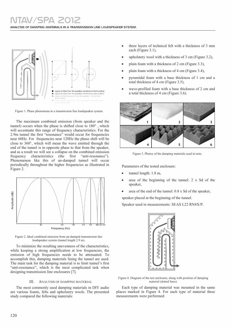
upholstery wool with a thickness of 3 cm:
Figure 8. Measurements of enclosure damped with upholstery wool. Far field (top), near field at tunnel exit (middle, shifted by -45 dB), speaker impedance
(bottom), and control measurement without damping (background).
The effect of the upholstery wool is similar to that caused by the felt. The antiresonance decreased slightly, but still the far field characteristic is very uneven. The tunnel’s self-resonance is reduced to about 42Hz, which suggests a greater reduction of the wave velocity in the tunnel.
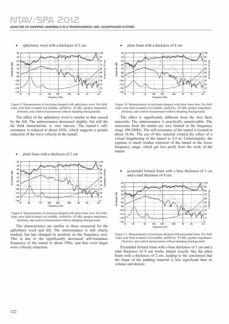
plain foam with a thickness of 2 cm:
Figure 9. Measurements of enclosure damped with plain foam 2cm. Far field (top), near field at tunnel exit (middle, shifted by -45 dB), speaker impedance
(bottom), and control measurement without damping (background).
The characteristics are similar to those measured for the upholstery wool and felt. The antiresonance is still clearly marked, but has changed its position on the frequency axis. This is due to the significantly decreased self-resonance frequency of the tunnel to about 39Hz, and thus even larger wave velocity reduction.
plain foam with a thickness of 4 cm:
Figure 10. Measurements of enclosure damped with plain foam 4cm. Far field (top), near field at tunnel exit (middle, shifted by -45 dB), speaker impedance
(bottom), and control measurement without damping (background).
The effect is significantly different from the first three materials. The antiresonance is practically unnoticeable. The emissions from the tunnel are very limited in the frequency range 100-200Hz. The self-resonance of the tunnel is located at about 36 Hz. The use of this material created the effect of a virtual lengthening of the tunnel to 2.4 m. Unfortunately, the expense is much weaker emission of the tunnel in the lower frequency range, which get less profit from the work of the tunnel.
pyramidal formed foam with a base thickness of 1 cm and a total thickness of 4 cm:
Figure 11. Measurements of enclosure damped with pyramidal foam. Far field (top), near field at tunnel exit (middle, shifted by -45 dB), speaker impedance
(bottom), and control measurement without damping (background).
Pyramidal formed foam with a base thickness of 1 cm and a total thickness of 4 cm works almost exactly like the plain foam with a thickness of 2 cm, leading to the conclusion that the shape of the padding material is less significant than its volume and density.
analysis of Damping Materials in a Transmission Line Loudspeaker System
ntav/spa 2012
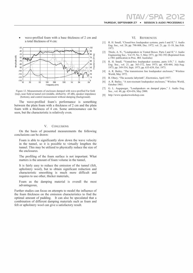
wave-profiled foam with a base thickness of 2 cm and a total thickness of 4 cm:
Figure 12. Measurements of enclosure damped with wave-profiled Far field (top), near field at tunnel exit (middle, shifted by -45 dB), speaker impedance
(bottom), and control measurement without damping (background).
The wave-profiled foam’s performance is something between the plain foam with a thickness of 2 cm and the plain foam with a thickness of 4 cm. Some antiresonance can be seen, but the characteristic is relatively even.
V. CONLUSIONS On the basis of presented measurements the following
conclusions can be drawn:
Foam is able to significantly slow down the wave velocity in the tunnel, so it is possible to virtually lengthen the tunnel. This may be utilized to physically reduce the size of the enclosures.
The profiling of the foam surface is not important. What matters is the amount of foam volume in the tunnel,
It is fairly easy to reduce the emission of the tunnel (felt, upholstery wool), but to obtain significant reduction and characteristic smoothing is much more difficult and requires to use other, thicker materials,
Foam as the damping material is overall the most advantageous,
Further studies can focus on attempts to model the influence of the foam thickness on the emission characteristics to find the optimal amount of padding. It can also be speculated that a combination of different damping materials such as foam and felt or upholstery wool can give a satisfactory result.
VI. REFERENCES [1] R. H. Small, “Closed-box loudspeaker systems, parts I and II,” J. Audio
Eng. Soc., vol. 20, pp. 798-808, Dec. 1972; vol. 21, pp. 11-18, Jan./Feb. 1973.
[2] Thiele, A. N., "Loudspeakers in Vented Boxes: Parts I and II," J. Audio Engineering Soc., Vol 19, No. 5, May 1971, pp 382-392 (Reprinted from a 1961 publication in Proc. IRE Australia)
[3] R. H. Small, “Vented-box loudspeaker systems, parts I-IV,” J. Audio Eng. Soc., vol. 21, pp. 363-372, June 1973; pp. 438-444, July/Aug. 1973; pp. 549-554, Sept. 1973; pp. 635-639, Oct. 1973.
[4] A. R. Bailey, “The transmission line loudspeaker enclosure,” Wireless World, May 1972.
[5] B. Olney, “The acoustic labyrinth”, Electronics, April 1937. [6] A. R. Bailey, “A non-resonant loudspeaker enclosure,” Wireless World,
October 1965. [7] G. L. Augspurger, “Loudspeakers on damped pipes,” J. Audio Eng.
Soc., vol. 48, pp. 424-436, May 2000. [8] http://www.speakerworkshop.com
Thursday, September 27 • SESSION 3: audio Processing II