analysis of cracking in rc tensile members using …
TRANSCRIPT

Proceedings of the 5th International Conference on Integrity-Reliability-Failure, Porto/Portugal 24-28 July 2016 Editors J.F. Silva Gomes and S.A. Meguid Publ. INEGI/FEUP (2016)
-553-
PAPER REF: 6235
ANALYSIS OF CRACKING IN RC TENSILE MEMBERS USING BEAM FINITE ELEMENTS WITH EMBEDDED TRANSVERSAL CRACKING Paulo Šćulac(*), Gordan Jelenić
Faculty of Civil Engineering, University of Rijeka, Rijeka, Croatia (*)
Email: [email protected] ABSTRACT
In this paper we present our recent work on modelling cracking mechanism in reinforced-concrete members subjected to uniaxial tension. A novel embedded-crack beam/bar finite element is proposed, in which crack formation and development, as well as the stress transfer between the reinforcement bars and surrounding concrete matrix are implemented, and tested for monotonically increasing loading. The proposed approach is capable of determining both the position and width of an opening crack. Particular emphasis is given to the numerical problems related to the arc-length solution procedure used to track the complete load-displacement response of the member.
Keywords: Beam element, embedded discontinuity, arc-length method, crack width and spacing, bond, slip
INTRODUCTION
Modelling crack formation and development by means of the finite element method requires sophisticated numerical non-linear procedures. While much work has been conducted using planar and spatial continuum-based finite elements (see e.g. Rots, 1988; Prasad, 2002; Oliver, 2004; Wu, 2009), the one-dimensional beam elements, based on relatively simple beam hypotheses – which effectively reduce the number of degrees of freedom needed to describe the element behaviour, have been used far less. The aim of this research is to come up with an accurate and effective computational model for the analysis of reinforced-concrete (RC) tensile members based on the use of beam elements.
Although RC tensile members are actually not very often found in practice, they are widely used to represent the tensile regions in RC members subjected to e.g. bending, and to study the interaction and stress transfer between the reinforcement bars and surrounding concrete under tension. The formation of cracks results in a reduction in the stiffness of the member, and produces a number of challenging convergence problems. In order to capture the entire solution path the use of the arc-length controlled family of procedures will be investigated.
BEAM FINITE ELEMENT WITH EMBEDDED TRANSVERSAL CRACKING
A multi-layered embedded-discontinuity beam/bar element has been recently derived in which a crack opens when the tensile stresses in concrete at pre-defined points reach the tensile strength. Detailed formulation of the kinematics of cracking of concrete in tension and slippage of reinforcement bars may be found in Šćulac (2014).
Topic_J: Civil Engineering Applications
-554-
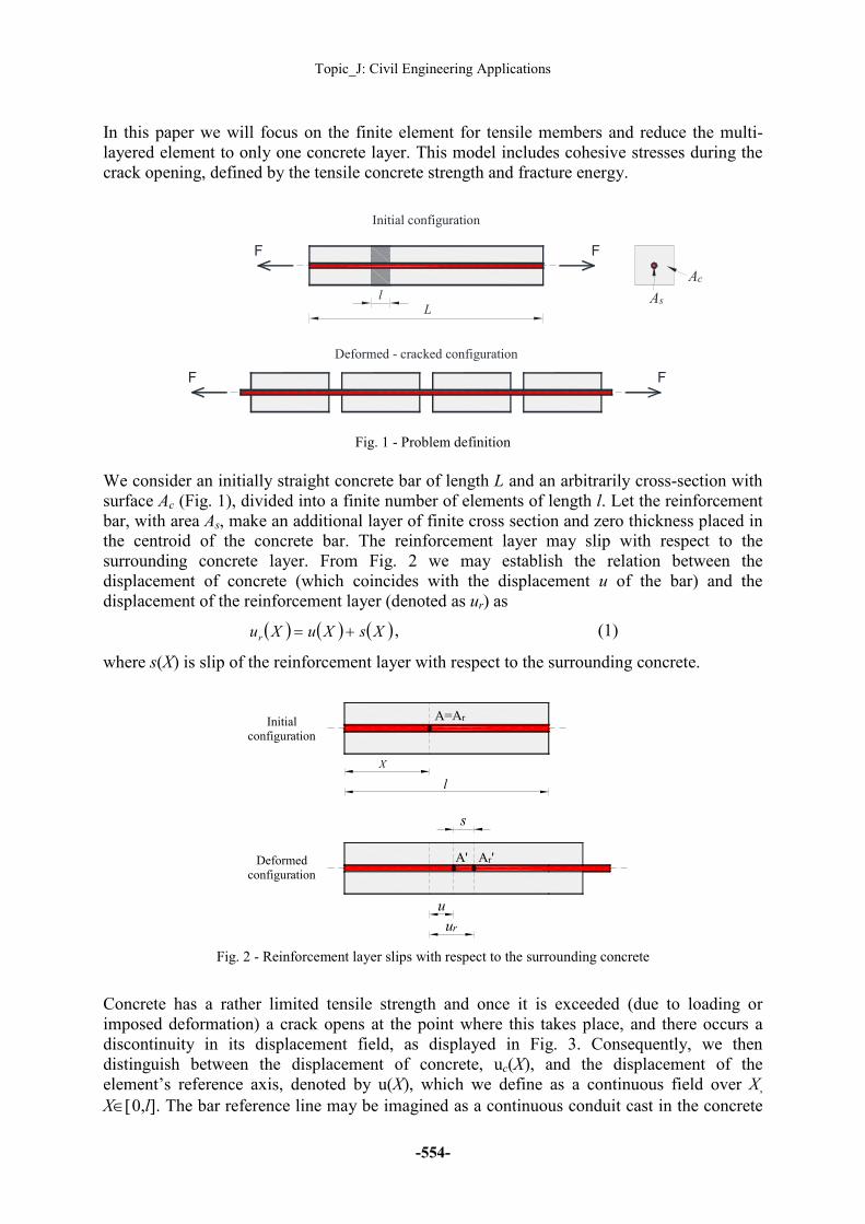
In this paper we will focus on the finite element for tensile members and reduce the multi-layered element to only one concrete layer. This model includes cohesive stresses during the crack opening, defined by the tensile concrete strength and fracture energy.
Fig. 1 - Problem definition
We consider an initially straight concrete bar of length L and an arbitrarily cross-section with surface Ac (Fig. 1), divided into a finite number of elements of length l. Let the reinforcement bar, with area As, make an additional layer of finite cross section and zero thickness placed in the centroid of the concrete bar. The reinforcement layer may slip with respect to the surrounding concrete layer. From Fig. 2 we may establish the relation between the displacement of concrete (which coincides with the displacement u of the bar) and the displacement of the reinforcement layer (denoted as ur) as
( ) ( ) ( )XsXuXur += , (1)
where s(X) is slip of the reinforcement layer with respect to the surrounding concrete.
Fig. 2 - Reinforcement layer slips with respect to the surrounding concrete
Concrete has a rather limited tensile strength and once it is exceeded (due to loading or imposed deformation) a crack opens at the point where this takes place, and there occurs a discontinuity in its displacement field, as displayed in Fig. 3. Consequently, we then distinguish between the displacement of concrete, uc(X), and the displacement of the element’s reference axis, denoted by u(X), which we define as a continuous field over X, X∈[0,l]. The bar reference line may be imagined as a continuous conduit cast in the concrete
Ac
AsL
FF
Initial configuration
Deformed - cracked configuration
F F
l
X
l
Initialconfiguration
Deformedconfiguration
A=Ar
Ar'A'
u
ur
s

Proceedings of the 5th International Conference on Integrity-Reliability-Failure
-555-
bar. When concrete cracks, it also slips with respect to this conduit by p(X), where p(X) is a function accounting for the discontinuity at the crack position XC. The two fields are related via
( ) ( ) ( )XpXuXuc += . (2)
This function may be approximated as
( ) ( )wXkXp Cδ= , (3)
where δC is a flag denoting if concrete has cracked or not
>
≤=
cct
cct
CEf
Ef
/,1
/,0
εε
δ , (4)
with ε as the normal strain, fct as the tensile strength of concrete and Ec as the Young’s modulus of concrete. The crack opening is denoted as w, while k(X) is a step function which is functionally undefined at X=XC (Fig. 3).
Fig. 3 - Discontinuity in the displacement field
The resulting bar finite element is derived using the axial displacement and slip of the reinforcement layer at each of the nodes and the crack opening as the internal degree of freedom.
Fig. 4 - Discontinuous step function (crack position XC may be chosen arbitrarily along the
element length)
X
l
Initialconfiguration
crackedconfiguration
A=Ac
A' Ac'
u
uc
w
deformed axis of the
element
deformed axis ofthe concrete
l0 XC
X
l-Xl
Xl
-
1

Topic_J: Civil Engineering Applications
-556-
MULTI-LINEAR BOND-SLIP RELATIONSHIP
Upon cracking the reinforcement layer slips with respect to the surrounding concrete, and the compatibility of deformations between reinforcement and the surrounding concrete is no more valid. The stress transfer between the reinforcement layer and the surrounding concrete is governed by a non-linear bond-slip constitutive relationship - in this paper adopted according to the model specified in CEB-FIP (1993), which is based on the values obtained from pull-out tests by Eligehausen (1983). This model is further simplified by approximating the initial exponential ascending part of the bond-slip model with a bilinear form (Fig. 4):
>
≤<−−
≤<
≤<−+
≤≤⋅
=
3
3223max
21max
10200
01
,
),(
,
,)(
0,
)(
ff
fffffk
fff
fffkff
ffkf
f
fττ
ττ
τ (5)
with
0
01
fk
τ= ,
01
0max2
ffk
−−
=ττ ,
23
max3
ffk
f
−
−=
ττ, (6)
where the parameters used to define the piecewise linear relationship are: τ0 is bond stress corresponding to slip f0, τmax is maximum bond stress, τf is residual (frictional) bond strength; f1 is slip corresponding to the maximum bond strength, f2 is slip defining the end of the horizontal plateau, f3 is slip corresponding to the residual bond strength. The model is further extended to account for limited unloading and reloading states that may take place even under monotonic applied loading due to gradually increasing number of cracks (see e.g. Yankelevsky, 2008; Zanuy, 2010). The unloading branch is assumed to be linear with stiffness kunload, and the subsequent reloading is also linear with the same stiffness.
Fig. 5 - Multi-linear bond-slip relationship
INCLUSION OF A COHESIVE CRACK MODEL
In this section we define the virtual work due to cohesive stresses during the crack opening. In the cohesive crack model approach the entire fracture process zone is lumped into the crack line and characterized in the form of a stress-displacement relationship which exhibits softening (Bažant, 1998). According to the model introduced by Hillerborg (1976), stresses are still assumed to act across a crack as long as it is narrowly opened. We assume that the crack will open as soon as the stresses at crack location reach the tensile strength fct. When the
τ
f0
τmax
τf
τ0
f f1 f2 f3
kunload

Proceedings of the 5th International Conference on Integrity-Reliability-Failure
-557-
crack opens, the stress is not assumed to reduce to zero at once, but to decrease with increasing crack width until the fracture energy Gf, which depends on the concrete class and the grain-size distribution of aggregate has been expended. Geometrically, Gf coincides with the area under the softening curve.
a) prior to crack formation (stress-strain) b) after crack formation (stress-crack opening)
Fig. 6 - Definition of tensile stresses in concrete
The most basic bilinear damage constitutive law may be defined for a uniaxial stress-strain state (which implies a mode I. fracture) as (Fig. 6):
>
>
≤≤
−
≤
=
E
f
ww
www
wf
E
fE
ctct
ct
ε
εε
σ
0
00
,0
0,1
,
, (7)
where w0=2Gf/fct is the maximum crack opening for which the crack may still sustain a stress. Even though only monotonic loading is considered, unloading is also induced due to the opening of new cracks. A history variable has been introduced for the crack opening (wmax) in which the maximum value at the previously converged state is recorded. In case of unloading the decrease follows the secant stiffness line from the maximum (σmax) to the origin of the coordinate system. In reloading we follow the secant stiffness line up to the point at the maximum previously converged state. The stress-crack opening law from expression (7) may be thus redefined as
( )
≥
>
≤≤
−
<>
≤≤
==
max
0
00
max
0
0maxmax
0
01
0
0
ww
ww
www
wf
ww
ww
www
w
w
ct
σ
σσ (8)
where
−=
0
maxmax 1
w
wfctσ .
crack width w
σ
ε w0
f ctf ct
f ct/E
σ
Gf
wmax
σmax

Topic_J: Civil Engineering Applications
-558-
The virtual work due to the beam, bond and reinforcement contributions defined in Šćulac (2014) now has to be complemented with the virtual work of the cohesive stresses:
( )wAwNwV cccc σδδ == , (9)
where w is the virtual crack opening.
ARC-LENGTH METHOD SOLVING PROCEDURE
Numerical problems are often encountered while modelling crack formation and development, especially when sharp snap-back behaviour in load-displacement relationships are expected (Yang, 2004). The principle behind the arc-length method is to advance along the load-displacement path in such a manner to use the benefits of both load and displacement control. The main idea of the arc-length controlled family of procedures consists of adding an extra constraint so as to limit the length of the incremental solution (see e.g. de Souza Neto, 2008). Here the most widely used cylindrical arc-length method (Crisfield, 1991) has been used, where the constraint equation has the form:
( ) ( ) 200 c
T =−− pppp , (10)
where p is the global vector of nodal unknowns, p0 is the global vector of nodal unknowns corresponding to the last converged equilibrium state and c is a prescribed incremental arc-length. Expression (10) leads to a quadratic equation with two roots, corresponding to the two intersection points between the constraint surface and the solution path. The standard solution procedure consists of two phases: the predictor and the corrector phase. In order to select the correct root, in the predictor solution phase we use the secant path direction prediction which according to de Souza Neto (1999) produces a reliable path direction prediction, even in the presence of bifurcations and snap-backs. In the corrector phase, the root is selected such that the angle between the incremental vector of nodal unknowns before the current iteration and incremental vector of nodal unknowns after the current iteration has a minimum value.
Several problems have been encountered during the implementation of the standard arc-length procedure described above. Firstly, there are difficulties with the occurrence of complex roots arising from the arc-length constraint equation when there is no intersection between the constraint surface and the solution path (for example where cohesive stresses are not used - the solution path is discontinuous). When this condition is not met the usual practice involves reducing the step length and resuming the iterative procedure (Ritto-Correa, 2008), but here this has mostly proven ineffective. Secondly, there are problems concerning the load increment. If the load step is too large, either a negative crack opening is encountered or several adjacent elements crack (instead of one only). If the load step is too small we again encounter the complex roots and no solution. The detail will be given in the following section.
NUMERICAL EXAMPLE
A RC tie of square cross-section containing a reinforcing bar running through the centroid of the cross-section, for which an analytical solution was proposed by Yankelevsky (2008) will be used for testing the proposed element. The geometry of the tie is given in Fig. 7. The tie is loaded with monotonically increasing tensile force applied to the reinforcing bar protruding from each end of the concrete element up to the yielding of reinforcement. The material parameters are given as: Young’s modulus of concrete Ec = 29 000 MPa; concrete tensile strength fct = 3,1 MPa; concrete compressive strength fc = 22,95 MPa; Young’s modulus of

Proceedings of the 5th International Conference on Integrity-Reliability-Failure
-559-
steel Es = 210 000 MPa; yield strength fy = 460 MPa. Both steel and concrete are assumed to have linear-elastic behaviour. The values of the bond-slip relationship read τ0 = 6 MPa; τmax = 12 MPa; τf = 5 MPa; f0 = 0,03 mm; f1 = 1 mm; f2 = 3 mm; f3 = 10 mm; kunload = k1 = 200 MPa/mm. Yankelevsky (2008) did not consider cohesive stresses, so the fracture energy has been approximately selected as Gf = 100 N/m and hence w0 = 0,065 mm.
Fig. 7 - Geometry and discretized model
The discretised model contains 33 linear elements of the same length except for the first and the last element the length of which is halved in order to match the exact crack positions obtained analytically. The position of the crack is assumed in the middle of an element (Xc=l/2). The tie is fixed at the left-hand end (axial displacement set to zero), while the right-hand end is free; the slip of the reinforcement layer is allowed at both ends. The global coordinate reference system is placed at the left-hand end of the tie. The cylindrical arc-length method is used in combination with Newton-Raphson method to trace the complete load-displacement response of the member. The incremental arc-length parameter c is not kept fixed (equal) in all the iterations - it is instead reduced in the vicinity of limit points and increased in between, in order to reduce the computational time. Special attention must be given in choosing the right value of c just before the first cracking - if the parameter is too large several adjacent elements crack (instead of one element only) since the variation of strains in the middle of the tie is rather small. In this example when the approximate position of the first cracking has been located the parameter c has been reduced from 0.00001 to 0.0000001. A parametric study has been conducted in order to analyse different stress crack-opening law slopes on the member response. Unexpectedly, we noticed that if the slope of the stress crack-opening law is too steep, a negative crack width is encountered. It seems that this happens for every w0 that is smaller than the crack width obtained without the cohesive stresses. This is also valid for the displacement-control procedure. Difficulties with the occurrence of complex roots arising from the arc-length constraint equation when there is no intersection between the constraint surface and the solution path are also encountered. Possible solutions may be in appropriate changing (either to increase or to decrease) the parameter c. Finally, when we consider the model without cohesive stresses the procedure fails (no real roots) regardless of the arc-length parameter. On the other hand, the displacement-control method has no such problems and provides the solution path. In Fig. 8 the force-elongation diagram is illustrated, where a good agreement with the analytical solution may be observed (note that the analytical solution was obtained using a load-control so there is a part of the solution path missing). Prior to cracking the tie behaves as linear-elastic. With increasing load, the cracking occurs which may be noticed in abrupt
FF
L= 750 mm D= 90 mm
FF
φ12

Topic_J: Civil Engineering Applications
-560-
displacement jumps in the figure. The first crack opens in the middle of the tie; the second and third crack open at the same force value at the middle of the right and the left half of the tie respectively (L/4 from both ends of the tie). Although the tie has cracked, the intact concrete between the cracks continues to sustain a tensile stress and the tie response is much stiffer than the response of the bare rebar.
Fig. 8 - Force - elongation of the reinforcement bar
A comparison of the force-elongation relationship with and without cohesive stresses considered is shown in Fig. 9. The results for the model without cohesive stresses have been obtained using the displacement-control method. When cohesive stresses are not included upon cracking there is a sudden jump (dashed line) in the solution path which is actually a disconnected “curve”. When the crack width gets greater than the maximum crack width w0, at which there are no more cohesive stresses, there is no difference between the two solutions.
Fig. 9 - Force - elongation relationship: with and without cohesive stresses
L/2 L/2
L/4 L/4 L/4 L/4
1st crack
2nd & 3rd crack
L
F
F
F
F
F
F

Proceedings of the 5th International Conference on Integrity-Reliability-Failure
-561-
The variation of crack widths is given in Fig. 10. When the second and third crack open, the first crack partially closes due to redistribution of stresses in concrete. Although the tie is divided in four equal parts after second cracking, the first crack is not the same width as the second and the third crack. This occurs due to the bond-slip relationship applied which leads to different conditions at the cracks and consequently different crack widths (Yankelevsky, 2008). With increasing load this differences vanish, and all the crack widths tend to become of the same width.
Fig. 10 - Tensile force - crack width relationship
Fig.11 shows a comparison of crack widths with analytical solution. Small differences between the analytical solution and the proposed model occur as a result of the different forces that cause cracking in the analytical and the proposed model. When cohesive stresses are not included, after the crack opens the force drops significantly more than in the model with included cohesive stresses, and this happens suddenly.
a) first crack b) second and third crack
Fig. 11 - Variation of crack widths - comparison with analytical solution

Topic_J: Civil Engineering Applications
-562-
Fig. 12 illustrates variation of concrete strains and accompanying stresses in reinforcement before and after cracking (in order to compare with the analytical solution in the proposed model we take the results when the force reaches again the value at which the element cracks), where a good agreement with the analytical solution may be noticed. Since linear interpolation is used in the elements, the strains are constant within an element. When cohesive stresses are not considered the tensile strain in concrete at the crack position immediately drops to zero, while with cohesive stresses the strain in concrete exists as long as the crack width is smaller than w0.
(a) concrete
b) reinforcing bar
Fig. 12 - Variation of strains before crack formation, after 1st cracking (a crack formed in
the middle of the tie) and after 2nd cracking (two new cracks formed)

Proceedings of the 5th International Conference on Integrity-Reliability-Failure
-563-
CONCLUSION
This work presents an embedded discontinuity bar finite element with the ability to predict crack occurrence and development in RC ties. The element is derived on the basis of the discrete-crack approach, in which a strong discontinuity in the material takes place at the fully developed crack position. Results obtained using the proposed element have been found to agree well with analytical solution.
Several numerical problems have been encountered related to the cylindrical arc-length procedure, used to obtain the solution path, related to the issue of complex roots arising from the solution of the quadratic equation, negative crack opening and size of the load increment. Special attention must be given in choosing the right value of the incremental arc-length parameter just before the cracking occurs (limit point). If cohesive stresses are not included, solution can not be obtained using the arc-length method, but only with the displacement-control method. Another issue refers to the slope of the stress crack-opening law - in case it is too steep a negative crack width is encountered. All these issues require further analysis.
Future work will also include validation of the proposed element using experimental test data, where due to nonhomogeneous material properties the cracks do not appear at the expected positions hence randomly distributed tensile strength along the element will be employed.
ACKNOWLEDGMENTS
This work has been supported by the Croatian Science Foundation under the research project IP 11-2013-1631 (Configuration-dependent approximation in non-linear finite-element analysis of structures).
REFERENCES
[1]-Bažant ZP, Planas J. Fracture and Size Effect in Concrete and Other Quasibrittle Materials. CRC Press LLC, 1998.
[2]-CEB-FIP. CEB-FIP Model Code 1990: Design Code. London: Thomas Telford.1993.
[3]-Crisfield MA. Non-linear Finite Element Analysis of Solids and Structures (Volume 1). John Wiley and Sons, 1991.
[4]-Eligehausen R, Popov EP, Bertero VV. Local bond stress-slip relationship of deformed bars under generalized excitations. Report No. UCB/EERC 83-23, University of California, Berkeley, 1983.
[5]-Rots JG. Computational modelling of concrete structures. PhD thesis, Delft University of Technology, Delft, 1988.
[6]-Oliver J, Huespe AE. Theoretical and computational issues in modelling material failure in strong discontinuity scenarios. Computer Methods in Applied Mechanics and Engineering, 2004, 193, p. 2987-3014.
[7]-Prasad MVKV, Krishnamoorthy CS. Computational model for discrete crack growth in plain and reinforced concrete. Computer Methods in Applied Mechanics and Engineering, 2002, 191, p. 2699-2725.

Topic_J: Civil Engineering Applications
-564-
[8]-Ritto-Correa M, Camotim D. On the arc-length and other quadratic control methods: Established, les known and new implementation procedures. Computers and Structures, 2008, 86, p. 1353-1368.
[9]-de Souza Neto EA, Perić D, Owen DRJ. Computational Methods for Plasticity: Theory and Applications. Wiley, 2008.
[10]-de Souza Neto EA, Feng YT. On the determination of the path direction for arc-length methods in the presence of bifurcations and “snap-backs”. Computer Methods in Applied Mechanics and Engineering, 1999, 179, p. 91-89.
[11]-Šćulac P, Jelenić G, Škec L. Kinematics of layered reinforced-concrete planar beam finite elements with embedded transversal cracking. International Journal of Solids and Structures, 2014, 51, p. 74-92.
[12]-Šćulac P, Jelenić G. Modelling cracking in reinforced-concrete beams using beam finite elements with emebedded discontinuity, Computational Modelling of Concrete Structures, Bićanić et al. (Eds.), Taylor & Francis Group, London, 2014, ISBN 978-1-138-00145-9, p. 569-578.
[13]-Wu HQ, Gilbert RI. Modelling short-term tension stiffening in reinforced concrete prisms using a continuum-based finite element model. Engineering Structures, 2009, 31, p. 2380-2391.
[14]-Yang ZJ, Proverbs D. A comparative study of numerical solutions to non-linear discrete crack modelling of concrete beams involving sharp snap-back. Engineering Fracture Mechanics, 2004, p. 81-105.
[15]-Yankelevsky DZ, Jabareen M, Abutbul AD. One-dimensional analysis of tension stiffening in reinforced concrete with discrete cracks. Engineering Structures, 2008, 30, p. 206-217.
[16]-Zanuy C, Albajar L, de la Fuente P. On the cracking behaviour of the reinforced concrete tension chord under repeated loading. Materials and Structures, 2010, 43, p. 611-632.