analysis of atf ext/ff orbit jitter and extrapolation to ip (data of 2014.11.18) atf2 project...
TRANSCRIPT

Analysis of ATF EXT/FF OrbitJitter and extrapolation to IP
(Data of 2014.11.18)
ATF2 Project Meeting 2015. 2 K. Kubo

Data taking
• Data taken in November 18 (2014) swing shift.• After IP beam size tuning, observing modulation
with IPBSM 174 degree mode. (10x1 optics)– Positions of the BPM reference cavity and OTR2 chanber
were optimized.
• Data of EXT/FF BPM are saved with several conditions. (See Log Note)
• This report used data of– One file (2000 pulses) with bunch intensity
intentionally changed by hand.– 3 files (1000 pulses), each is for fixed bunch
intensity setting. (N~8.5E9, 4.9E9, 1.8E9)

BPM reading vs, pulse number(MQD10BFF: Large beta_y)
-100
0
100
200
300
400
500
-600
-400
-200
0
200
400
600
0 500 1000 1500 2000
x y
x (
m) y (
m)
pulse number
In horizontal, drift is larger compare with pulse to pulse jitter.In vertical, pulse to pulse jitter is more significant.(It may be only in this particular case. (?))

Analysis using SVD
pulse3-BPM2xpulse3-BPM1ypulse3-BPM1x
pulse2-BPM2xpulse2-BPM1ypulse2-BPM1x
pulse1-BPM2xpulse1-BPM1ypulse1-BPM1x
M
UWVM
3
2
1
00
00
00
w
w
w
W
W: Diagonal matrix of singular values U_ij represents amplitude of mode j in pulse i
V_kl represents response of monitor l to mode k
pulse
monitor
(Average is subtracted for each monitor)(Data far from average (>5-sigma) removed. BPM noise, etc.)
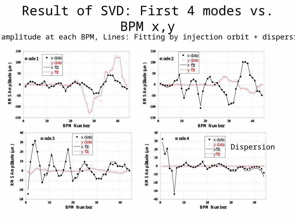
Result of SVD: First 4 modes vs. BPM x,y
Circles: amplitude at each BPM, Lines: Fitting by injection orbit + dispersion (model)
-150
-100
-50
0
50
100
150
0 10 20 30 40
x datay datax fity fit
RM
S A
mp
litu
de (m
)
BPM Number
mode 2
-150
-100
-50
0
50
100
150
0 10 20 30 40
x datay datax fity fit
RM
S A
mp
litu
de (m
)
BPM Number
mode 1
-30
-20
-10
0
10
20
30
40
0 10 20 30 40
x datay datax fity fit
RM
S A
mp
litu
de (m
)
BPM Number
mode 3
-40
-30
-20
-10
0
10
20
30
40
0 10 20 30 40
x datay dataxfityfit
RM
S A
mp
litu
de (m
)
BPM Number
mode 4
Dispersion

Result of SVD: other 2 modes vs. BPM x,y
-10
-5
0
5
10
0 10 20 30 40
x datay datax fity fit
RM
S A
mpl
itud
e (
m)
BPM Number
-15
-10
-5
0
5
10
15
20
25
0 10 20 30 40
x datay datax fity fit
RM
S A
mp
litu
de (m
)
BPM Number
mode 5
Intensity dependence Only seen in data with large intensity change
y position at IP phase

Standard deviation at each BPM in EXT/FF(not from SVD)
0
20
40
60
80
100
120
140
0 10 20 30 40
y stdv0.3*sigmay
y ji
tter
(m
)
BPM number
Horizontal: ~20%of beam size(emittance 2 nm assumed)
Vertical: ~40%of beam size(emittance 12 pm assumed)
(High intensity N~8.5E9)
0
50
100
150
200
0 10 20 30 40
x stdv0.3*sigmax
y ji
tter
(m
)
BPM number

Effect to IP position of some first modes -1
• 3 Different intensities (about 1000 pulses for each)– All BPMs used for fitting
Mode Vertical Jitter propagation to IP (nm)N~8.5E9 N~4.9E9 N~1.8E9
1 3.9 12.5 17.32 16.6 9.4 7.13 1.1 4.4 2.08 6.1 7.3 6.64 0.5 0.8 0.1
Total of mode 1 - 10 18.1 17.9 20.3
No intensity dependence.

Effect to IP position of some first 10 modes -2
Compared• Using All BPMs • Using only downstream BPMs
Used BPM Vertical Jitter propagation to IP (nm)N changed N~8.5E9 N~4.9E9 N~1.8E9
All 19.9 18.1 17.9 20.3From QD10AFF 1272 1258 1098 1139
From QF7FF 1000 974 863 882
Extrapolated to IP
Too large jitter using downstream BPMs only check waist shift (May be from optics error???)

Fitted orbit around IP (s=0)
s (m)Y
(m
icro
m)
s (m)
Y (
mic
rom
)
All BPMs used
BPM from MQD10AFF used
There is waist shift.(Note different scales)

Effect to position at waist of first 10 modes
• Using All BPMs • Using only downstream BPMs
Used BPM Vertical Jitter propagation to IP (nm)N changed N~8.5E9 N~4.9E9 N~1.8E9
All 8.5 6.4 9.1 8.0From QD10AFF 233 283 184 183
From QF7FF 251 213 208 210
Extrapolated to waist (not exactly IP)
Still large using BPMs only in downstream region

Simulation of SVD analysis• Create sets of EXT-FF BPM data
– Orbit jitter is given • At the beginning of the extraction line (injection
error)• Or position jitter of QD10BFF magnet• Or position jitter of All Q-magnets
– Beam position at every BPM is calculated by SAD– BPM resolution assumed
• 1 micron, or 100 nm for cavity BPMs• 10 micron for stlipline BPMs
• Apply the same analysis program for the real data.– Look at evaluated (extrapolated) y position jitter at IP by
SVD– Compare with “real” jitter at IP

Simulation result of SVD analysis -1injection jitter
0
5
10
15
20
25
30
35
40
0 5 10 15 20 25 30 35 40
Ext
rap
olat
ed y
jit
ter
at I
P b
y S
VD
(nm
)
real y jitter at ip (nm)
Evaluated jitter (all BPMs used) vs. Real jitter at IP Real jitter was changed by changing amplitude of injection jitter. Evaluated jitter include 10 SVD modes
Good resolution for injection jitter, using all BPMs
Resolution CavBPM: 1 um Stlipline: 10 um

Simulation result of SVD analysis -2jitter induced at QD10BFF
Evaluated jitter vs. Real jitter at IP “Real” jitter amplitude was changed by changing position jitter amplitude of QD10BFF. Evaluated jitter include 10 SVD modes 6 cases of used BPMs (and resolution) Use All BPMs from QD10AFF (1 um and 100 nm) from QF7FF (1 um and 100 nm)
Good estimation using BPMs downstream of jitter source only
0
20
40
60
80
100
120
140
160
0 20 40 60 80 100 120 140
simulation, orbit by QD10BFF offset
All BPM usedBPM from QD10AFF(resolution 1m)BPM from QD10AFF (resolution 100nm)BPM from QF7FF(resolution 1m)BPM from QF7FF(resolution100 nm)
Fit
ted
y j
itte
r at
IP
(n
m)
Real y jitter at IP (nm)
100 nm BPM resolution: good estimation1 um BPM resolution: over estimate jitter at IP by several x 10 nm.

Simulation result of SVD analysis -3jitter induced at all Quads
Evaluated jitter vs. Real jitter at IP “Real” jitter amplitude was changed by changing position jitter amplitude of all Quads in EXT-FF. Evaluated jitter include 10 SVD modes
Use All BPMs and use from MQD10AFFCavBPM resolution 100 nm and 1 um
Always underestimate jitter at IP
Bad BPM resolution makes estimated jitter large
0
20
40
60
80
100
120
140
0 20 40 60 80 100 120 140
Orbit by all Quads' vibration
All BPM, CavBPM rtesolution 100 nmAll BPM, CavBPM resolution 1 mBPM from MQD10A, resolution 100 nmBPM from MQD10A, resolution 1 m
Fit
ted
y j
itte
r at
IP
(n
m)
Real y jitter at IP (nm)

Fitted jitter depends on BPM resolutionjitter induced at all Quads
10
100
1000
0.1 1 10
Fit
ted
y j
itt
at I
P (
nm
)
Cav BPM resolution (m)
Orbit by vobration of all Q 20 nmReal jiier at IP = 35 nm
use BPMs from MQD10AFF
BPM resolution about 5 um may explain the large fitted jitter using BPMs in downstream part of FF line only. (about 200 nm at waist)
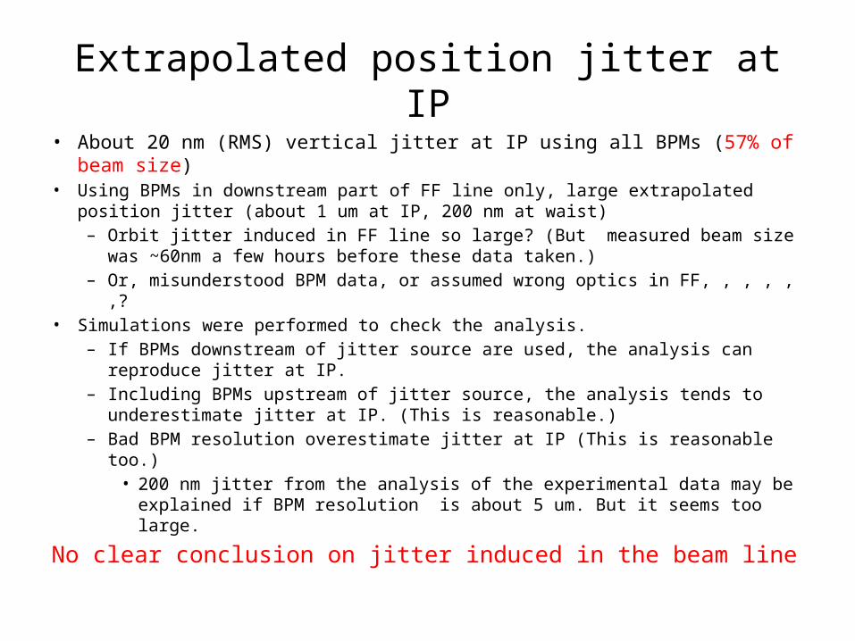
Extrapolated position jitter at IP
• About 20 nm (RMS) vertical jitter at IP using all BPMs (57% of beam size)
• Using BPMs in downstream part of FF line only, large extrapolated position jitter (about 1 um at IP, 200 nm at waist)– Orbit jitter induced in FF line so large? (But measured beam size was
~60nm a few hours before these data taken.)– Or, misunderstood BPM data, or assumed wrong optics in FF, , , , , ,?
• Simulations were performed to check the analysis.– If BPMs downstream of jitter source are used, the analysis can
reproduce jitter at IP. – Including BPMs upstream of jitter source, the analysis tends to
underestimate jitter at IP. (This is reasonable.)– Bad BPM resolution overestimate jitter at IP (This is reasonable too.)
• 200 nm jitter from the analysis of the experimental data may be explained if BPM resolution is about 5 um. But it seems too large.
No clear conclusion on jitter induced in the beam line

-1000
-500
0
500
1000
50 55 60 65 70 75 80 85 90
orbit y-at-IP phasey
IP = 37 nm, y'
IP = 0
y (n
m)
s (m)
-5 104
0
5 104
0 20 40 60 80
orbit y-at-IP phasey
IP = 37 nm, y'
IP = 0
y (n
m)
s (m)
NOTE: BPMs in downstream FF line is not so sensitive to Position-at-IP phase orbit
Using IPBPM will be probably necessary for reliable estimation of orbit difference induced in the FF line.

SUMMARY• Data of EXT/FF BPM taken in November 18 (2014) swing shift were
analyzed using Singular Value Decomposition method.• Vertical jitter at FF line BPMs (angle-at-IP phase) is a bout 40% of
beam size.• Position jitter at IP (or waist) estimated extrapolating orbits
calculated from SVD modes.– About 20 nm jitter from injection (or from upstream part of
EXT) jitter.– No intensity dependence.– Estimation of jitter induced in FF beam line was tried without
any clear results. • With more data, better optics information and careful BPM
calibration, some improved results may be possible. But,• Using IPBPM is simple for reliable estimation of position jitter at IP.