analysis & investigation of multifunctional dynamic...
TRANSCRIPT
78 | P a g e
ANALYSIS & INVESTIGATION OF
MULTIFUNCTIONAL DYNAMIC VOLTAGE
RESTORER IMPLEMENTATION FOR EMERGENCY
CONTROL IN DISTRIBUTION SYSTEMS
M.Padmarasan1, C.T.Manikandan
2, N.Anipriya
3, D.Shobana
4
1,2Assistant Professor (G-I),
3,4Assistant Professor,
Department of EEE, Panimalar Institute of Technology, Chennai
ABSTRACT
The dynamic voltage restorer (DVR) is one of the modern devices used in distribution systems to protect
consumers against sudden changes in voltage amplitude. Emergency control in distribution systems is discussed
by using the proposed multifunctional DVR control strategy in this paper. Also, the multi-loop controller using
the Posicast and P+Resonant controllers is proposed in order to improve the transient response and eliminate
the steady-state error in DVR response, respectively. The proposed algorithm is applied to some disturbances in
load voltage caused by induction motors starting, and a three-phase short circuit fault. Also, the capability of
the proposed DVR has been tested to limit the downstream fault current. The current limitation will restore the
point of common coupling (PCC) (the bus to which all feeders under study are connected) voltage and protect
the DVR itself. The innovation here is that the DVR acts as a virtual impedance with the main aim of protecting
the PCC voltage during downstream fault without any problem in real power injection into the DVR. Simulation
results show the capability of the DVR to control the emergency conditions of the distribution systems.
Keywords: Dynamic voltage restorer (DVR), emergency control, voltage sag, voltage swell.
I. INTRODUCTION
Voltage sag and voltage swell are two of the most important power-quality (PQ) problems that encompass
almost 80% of the distribution system PQ problems [1]. According to the IEEE 1959–1995 standard, voltage
sag is the decrease of 0.1 to 0.9 p.u. in the rms voltage level at system frequency and with the duration of half a
cycle to 1 min [2]. Short circuits, starting large motors, sudden changes of load, and energization of transformers
are the main causes of voltage sags [3].
According to the definition and nature of voltage sag, it can be found that this is a transient phenomenon whose
causes are classified as low or medium-frequency transient events [2]. In recent years, considering the use of
sensitive devices in modern industries, different methods of compensation of voltage sags have been used. One
of these methods is using the DVR to improve the PQ and compensate the load voltage [6]–[13].
Previous works have been done on different aspects of DVR performance, and different control strategies
have been found. These methods mostly depend on the purpose of using DVR. In some methods, the main
79 | P a g e
purpose is to detect and compensate for the voltage sag with minimum DVR active power injection [4], [5].
Also, the in-phase compensation method can be used for sag and swell mitigation [6]. The multiline DVR can
be used for eliminating the battery in the DVR structure and controlling more than one line [7], [14]. Moreover,
research has been made on using the DVR in medium level voltage [8]. Harmonic mitigation [9] and control of
DVR under frequency variations [10] are also in the area of research.
The closed-loop control with load voltage and current feedback is introduced as a simple method to control the
DVR in [15]. Also, Posicast and P+Resonant controllers can be used to improve the transient response and
eliminate the steady-state error in DVR. The Posicast controller is a kind of step function with two parts and is
used to improve the damping of the transient oscillations initiated at the start instant from the voltage sag. The
P+Resonant controller consist of a proportional function plus a resonant function and it eliminates the steady-
state voltage tracking error [16]. The state feedforward and feedback methods [17], symmetrical components
estimation [18], robust control [19], and wavelet transform [20] have also been proposed as different methods of
controlling the DVR.
In all of the aforementioned methods, the source of disturbance is assumed to be on the feeder which is parallel
to the DVR feeder. In this paper, a multifunctional control system is proposed in which the DVR protects the
load voltage using Posicast and P+Resonant controllers when the source of disturbance is the parallel feeders.
On the other hand, during a downstream fault, the equipment protects the PCC voltage, limits the fault current,
and protects itself from large fault current. Although this latest condition has been described in [11] using the
flux control method, the DVR proposed there acts like a virtual inductance with a constant value so that it does
not receive any active power during limiting the fault current. But in the pro-posed method when the fault
current passes through the DVR, it acts like a series variable impedance (unlike [11] where the equivalent
impedance was a constant).
The basis of the proposed control strategy in this paper is that when the fault current does not pass through the
DVR, an outer feedback loop of the load voltage with an inner feedback loop of the filter capacitor current will
be used. Also, a feedforward loop will be used to improve the dynamic response of the load voltage. Moreover,
to improve the transient response, the Posicast controller and to eliminate the steady-state error, the P+Resonant
controller are used. But in case the fault current passes through the DVR, using the flux control algorithm [11],
the series voltage is injected in the opposite direction and, therefore, the DVR acts like a series variable
impedance.
The remainder of this paper is organized as follows: The general operation of DVR and its state space
description are provided in Section II. The closed-loop control using Posicast and P+Resonant controllers has
been presented in Section III. In Section IV, the multifunctional DVR is introduced. The basis of the proposed
control method is described in Section V. Finally, the simulation results are provided in Section VI which shows
that the control capability of the proposed DVR system is satisfactory.
II. DVR COMPONENTS AND ITS BASIC OPERATIONAL PRINCIPLE
2.1 DVR Components
A typical DVR-connected distribution system is shown in Fig. 1, where the DVR consists of essentially a series-
connected injection transformer, a voltage-source inverter, an inverter output filter, and an energy storage device

80 | P a g e
that is connected to the dc link. Before injecting the inverter output to the system, it must be filtered so that
harmonics due to switching function in the inverter are eliminated. It should be noted that when using the DVR
in real situations, the injection transformer will be connected in parallel with a bypass switch (Fig. 1). When
there is no disturbances in voltage, the injection transformer (hence, the DVR) will be short circuited by this
switch to minimize losses and maximize cost effectiveness. Also, this switch can be in the form of two parallel
thyristors, as they have high on and off speed [21]. A financial assessment of voltage sag events and use of
flexible ac transmission systems (FACTS) devices, such as DVR, to mitigate them is provided in [22]. It is
obvious that the flexibility of the DVR output depends on the switching accuracy of the pulse width modulation
(PWM) scheme and the control method. The PWM generates sinusoidal signals by comparing a sinusoidal wave
with a saw tooth wave and sending appropriate signals to the inverter switches. A further detailed description
about this scheme can be found in [23].
Fig. 1. Typical DVR-connected distribution system.
2.2 Basic Operational Principle of DVR
The DVR system shown in Fig. 1, controls the load voltage by injecting an appropriate voltage phasor in
series with the system using the injection series transformer. In most of the sag compensation techniques, it is
necessary that during compensation, the DVR injects some active power to the system. There-fore, the capacity
of the storage unit can be a limiting factor in compensation, especially during long-term voltage sags.
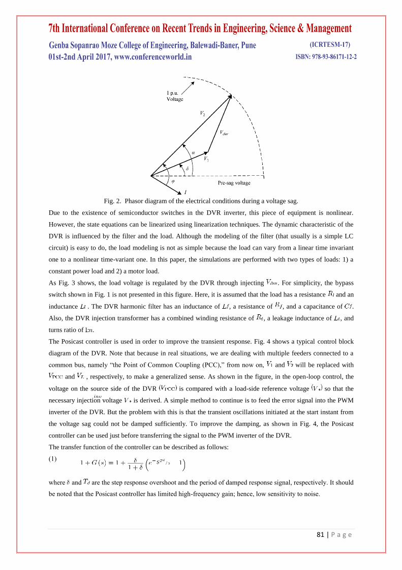
The phasor diagram in Fig. 2, shows the electrical conditions during voltage sag, where, for clarity, only one
phase is shown. Voltages , , and are the source-side voltage, the load-side voltage, and the DVR
injected voltage, respectively. Also, the operators I, , , and are the load current, the load power factor angle,
the source phase voltage angle, and the voltage phase advance angle, respectively [24]. It should be noted that in
addition to the in-phase injection technique, another technique, namely “the phase advance voltage
compensation technique” is also used [24]. One of the advantages of this method over the in-phase method is
that less active power should be transferred from the storage unit to the distribution system. This results in
compensation for deeper sags or sags with longer durations.
81 | P a g e
Fig. 2. Phasor diagram of the electrical conditions during a voltage sag.
Due to the existence of semiconductor switches in the DVR inverter, this piece of equipment is nonlinear.
However, the state equations can be linearized using linearization techniques. The dynamic characteristic of the
DVR is influenced by the filter and the load. Although the modeling of the filter (that usually is a simple LC
circuit) is easy to do, the load modeling is not as simple because the load can vary from a linear time invariant
one to a nonlinear time-variant one. In this paper, the simulations are performed with two types of loads: 1) a
constant power load and 2) a motor load.
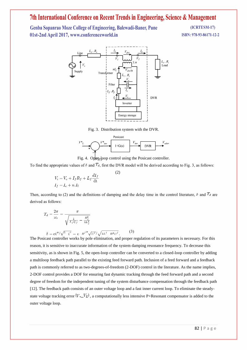
As Fig. 3 shows, the load voltage is regulated by the DVR through injecting . For simplicity, the bypass
switch shown in Fig. 1 is not presented in this figure. Here, it is assumed that the load has a resistance and an
inductance . The DVR harmonic filter has an inductance of , a resistance of , and a capacitance of .
Also, the DVR injection transformer has a combined winding resistance of , a leakage inductance of , and
turns ratio of .
The Posicast controller is used in order to improve the transient response. Fig. 4 shows a typical control block
diagram of the DVR. Note that because in real situations, we are dealing with multiple feeders connected to a
common bus, namely “the Point of Common Coupling (PCC),” from now on, and will be replaced with
and , respectively, to make a generalized sense. As shown in the figure, in the open-loop control, the
voltage on the source side of the DVR is compared with a load-side reference voltage so that the
necessary injection voltage is derived. A simple method to continue is to feed the error signal into the PWM
inverter of the DVR. But the problem with this is that the transient oscillations initiated at the start instant from
the voltage sag could not be damped sufficiently. To improve the damping, as shown in Fig. 4, the Posicast
controller can be used just before transferring the signal to the PWM inverter of the DVR.
The transfer function of the controller can be described as follows:
(1)
where and are the step response overshoot and the period of damped response signal, respectively. It should
be noted that the Posicast controller has limited high-frequency gain; hence, low sensitivity to noise.
82 | P a g e
Fig. 3. Distribution system with the DVR.
Fig. 4. Open-loop control using the Posicast controller.
To find the appropriate values of and , first the DVR model will be derived according to Fig. 3, as follows:
(2)
Then, according to (2) and the definitions of damping and the delay time in the control literature, and are
derived as follows:
(3)
The Posicast controller works by pole elimination, and proper regulation of its parameters is necessary. For this
reason, it is sensitive to inaccurate information of the system damping resonance frequency. To decrease this
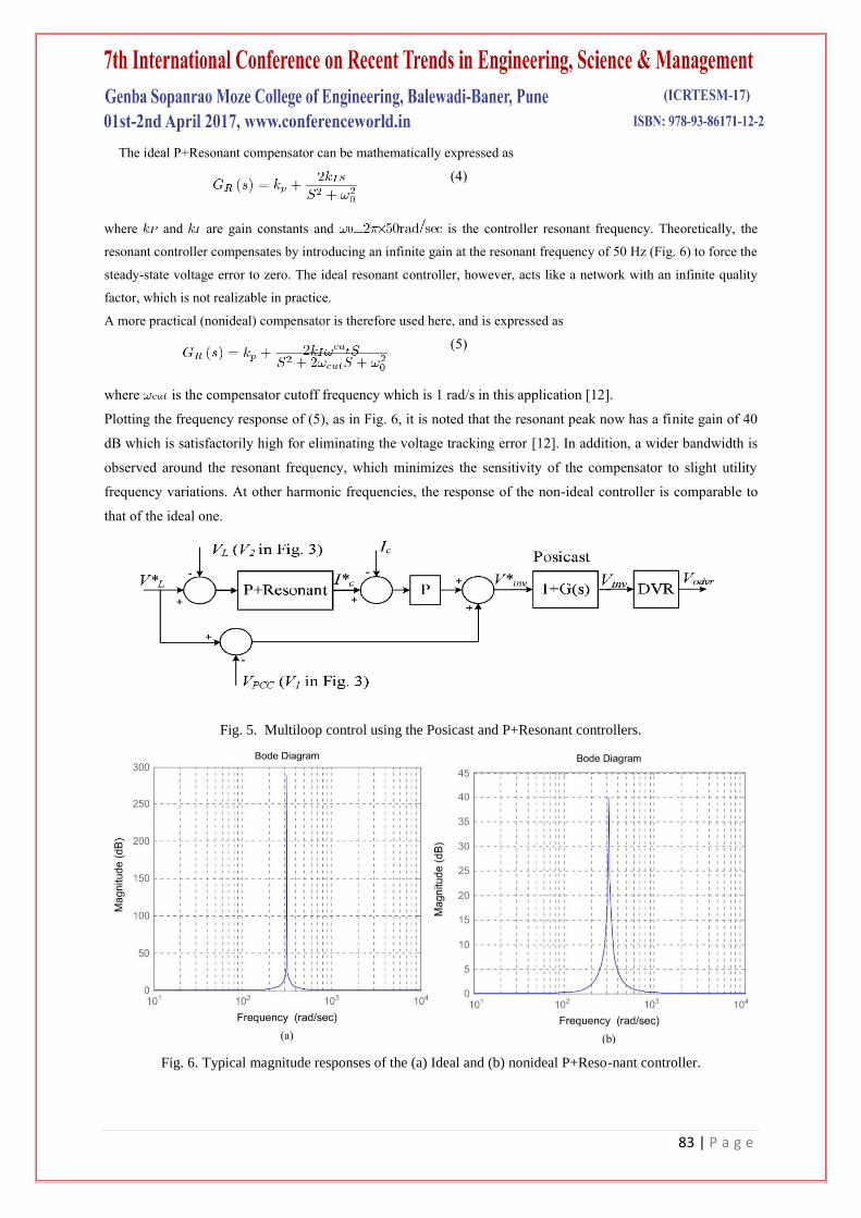
sensitivity, as is shown in Fig. 5, the open-loop controller can be converted to a closed-loop controller by adding
a multiloop feedback path parallel to the existing feed forward path. Inclusion of a feed forward and a feedback
path is commonly referred to as two-degrees-of-freedom (2-DOF) control in the literature. As the name implies,
2-DOF control provides a DOF for ensuring fast dynamic tracking through the feed forward path and a second
degree of freedom for the independent tuning of the system disturbance compensation through the feedback path
[12]. The feedback path consists of an outer voltage loop and a fast inner current loop. To eliminate the steady-
state voltage tracking error , a computationally less intensive P+Resonant compensator is added to the
outer voltage loop.
83 | P a g e
The ideal P+Resonant compensator can be mathematically expressed as
(4)
where and are gain constants and is the controller resonant frequency. Theoretically, the
resonant controller compensates by introducing an infinite gain at the resonant frequency of 50 Hz (Fig. 6) to force the
steady-state voltage error to zero. The ideal resonant controller, however, acts like a network with an infinite quality
factor, which is not realizable in practice.
A more practical (nonideal) compensator is therefore used here, and is expressed as
(5)
where is the compensator cutoff frequency which is 1 rad/s in this application [12].
Plotting the frequency response of (5), as in Fig. 6, it is noted that the resonant peak now has a finite gain of 40
dB which is satisfactorily high for eliminating the voltage tracking error [12]. In addition, a wider bandwidth is
observed around the resonant frequency, which minimizes the sensitivity of the compensator to slight utility
frequency variations. At other harmonic frequencies, the response of the non-ideal controller is comparable to
that of the ideal one.
Fig. 5. Multiloop control using the Posicast and P+Resonant controllers.
Fig. 6. Typical magnitude responses of the (a) Ideal and (b) nonideal P+Reso-nant controller.
84 | P a g e
III. PROPOSED MULTIFUNCTIONAL DVR
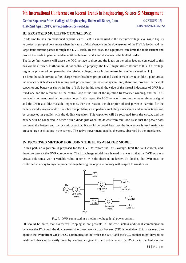
In addition to the aforementioned capabilities of DVR, it can be used in the medium-voltage level (as in Fig. 7)
to protect a group of consumers when the cause of disturbance is in the downstream of the DVR’s feeder and the
large fault current passes through the DVR itself. In this case, the equipment can limit the fault current and
protect the loads in parallel feeders until the breaker works and disconnects the faulted feeder.
The large fault current will cause the PCC voltage to drop and the loads on the other feeders connected to this
bus will be affected. Furthermore, if not controlled properly, the DVR might also contribute to this PCC voltage
sag in the process of compensating the missing voltage, hence further worsening the fault situation [11].
To limit the fault current, a flux-charge model has been pro-posed and used to make DVR act like a pure virtual
inductance which does not take any real power from the external system and, therefore, protects the dc-link
capacitor and battery as shown in Fig. 1 [11]. But in this model, the value of the virtual inductance of DVR is a
fixed one and the reference of the control loop is the flux of the injection transformer winding, and the PCC
voltage is not mentioned in the control loop. In this paper, the PCC voltage is used as the main reference signal
and the DVR acts like variable impedance. For this reason, the absorption of real power is harmful for the
battery and dc-link capacitor. To solve this problem, an impedance including a resistance and an inductance will
be connected in parallel with the dc-link capacitor. This capacitor will be separated from the circuit, and the
battery will be connected in series with a diode just when the downstream fault occurs so that the power does
not enter the battery and the dc-link capacitor. It should be noted here that the inductance is used mainly to
prevent large oscillations in the current. The active power mentioned is, therefore, absorbed by the impedance.
IV. PROPOSED METHOD FOR USING THE FLUX-CHARGE MODEL
In this part, an algorithm is proposed for the DVR to restore the PCC voltage, limit the fault current, and,
therefore, protect the DVR components. The flux-charge model here is used in a way so that the DVR acts as a
virtual inductance with a variable value in series with the distribution feeder. To do this, the DVR must be
controlled in a way to inject a proper voltage having the opposite polarity with respect to usual cases.
Fig. 7. DVR connected in a medium-voltage level power system.
It should be noted that overcurrent tripping is not possible in this case, unless additional communication
between the DVR and the downstream side overcurrent circuit breaker (CB) is available. If it is necessary to
operate the overcurrent CB at PCC, communication be-tween the DVR and the PCC breaker might have to be
made and this can be easily done by sending a signal to the breaker when the DVR is in the fault-current
85 | P a g e
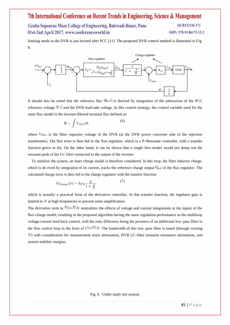
limiting mode as the DVR is just located after PCC [11]. The proposed DVR control method is illustrated in Fig.
8.
It should also be noted that the reference flux is derived by integration of the subtraction of the PCC
reference voltage and the DVR load-side voltage. In this control strategy, the control variable used for the
outer flux model is the inverter-filtered terminal flux defined as:
(6)
where is the filter capacitor voltage of the DVR (at the DVR power converter side of the injection
transformer). The flux error is then fed to the flux regulator, which is a P+Resonant controller, with a transfer
function given in (6). On the other hand, it can be shown that a single flux-model would not damp out the
resonant peak of the LC filter connected to the output of the inverter.
To stabilize the system, an inner charge model is therefore considered. In this loop, the filter inductor charge,
which is de-rived by integration of its current, tracks the reference charge output of the flux regulator. The
calculated charge error is then fed to the charge regulator with the transfer function
(7)
which is actually a practical form of the derivative controller. In this transfer function, the regulator gain is
limited to at high frequencies to prevent noise amplification.
The derivative term in neutralizes the effects of voltage and current integrations at the inputs of the
flux-charge model, resulting in the proposed algorithm having the same regulation performance as the multiloop
voltage-current feed-back control, with the only difference being the presence of an additional low–pass filter in
the flux control loop in the form of . The bandwidth of this low–pass filter is tuned (through varying
) with consideration for measurement noise attenuation, DVR LC-filter transient resonance attenuation, and
system stability margins.
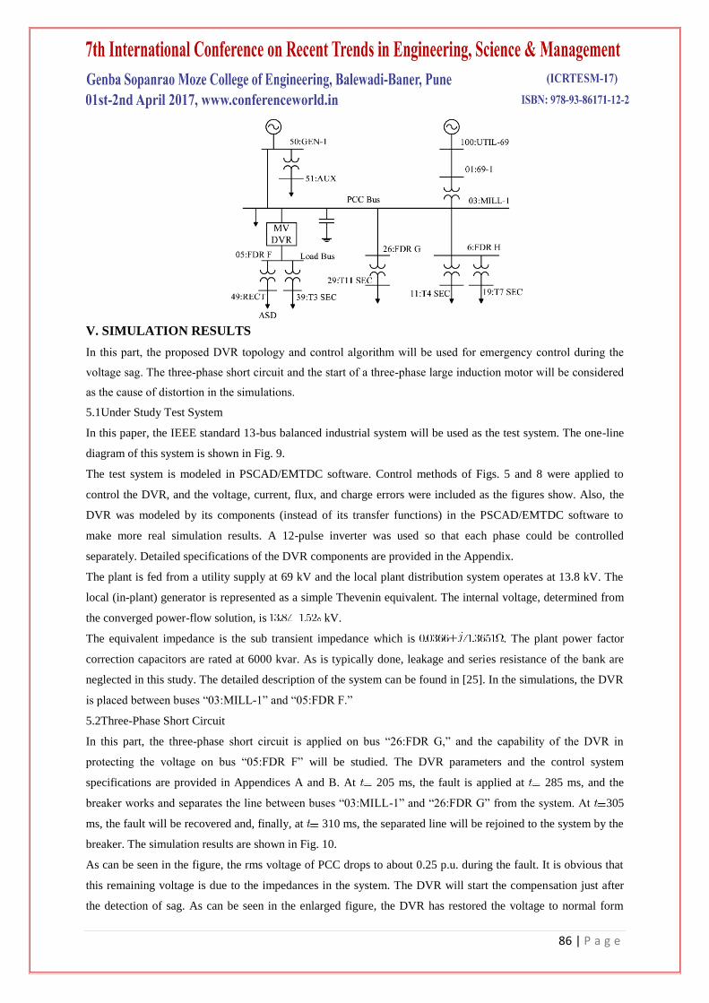
Fig. 9. Under study test system.
86 | P a g e
V. SIMULATION RESULTS
In this part, the proposed DVR topology and control algorithm will be used for emergency control during the
voltage sag. The three-phase short circuit and the start of a three-phase large induction motor will be considered
as the cause of distortion in the simulations.
5.1Under Study Test System
In this paper, the IEEE standard 13-bus balanced industrial system will be used as the test system. The one-line
diagram of this system is shown in Fig. 9.
The test system is modeled in PSCAD/EMTDC software. Control methods of Figs. 5 and 8 were applied to
control the DVR, and the voltage, current, flux, and charge errors were included as the figures show. Also, the
DVR was modeled by its components (instead of its transfer functions) in the PSCAD/EMTDC software to
make more real simulation results. A 12-pulse inverter was used so that each phase could be controlled
separately. Detailed specifications of the DVR components are provided in the Appendix.
The plant is fed from a utility supply at 69 kV and the local plant distribution system operates at 13.8 kV. The
local (in-plant) generator is represented as a simple Thevenin equivalent. The internal voltage, determined from
the converged power-flow solution, is kV.
The equivalent impedance is the sub transient impedance which is . The plant power factor
correction capacitors are rated at 6000 kvar. As is typically done, leakage and series resistance of the bank are
neglected in this study. The detailed description of the system can be found in [25]. In the simulations, the DVR
is placed between buses “03:MILL-1” and “05:FDR F.”
5.2Three-Phase Short Circuit
In this part, the three-phase short circuit is applied on bus “26:FDR G,” and the capability of the DVR in
protecting the voltage on bus “05:FDR F” will be studied. The DVR parameters and the control system
specifications are provided in Appendices A and B. At 205 ms, the fault is applied at 285 ms, and the
breaker works and separates the line between buses “03:MILL-1” and “26:FDR G” from the system. At 305
ms, the fault will be recovered and, finally, at 310 ms, the separated line will be rejoined to the system by the
breaker. The simulation results are shown in Fig. 10.
As can be seen in the figure, the rms voltage of PCC drops to about 0.25 p.u. during the fault. It is obvious that
this remaining voltage is due to the impedances in the system. The DVR will start the compensation just after
the detection of sag. As can be seen in the enlarged figure, the DVR has restored the voltage to normal form
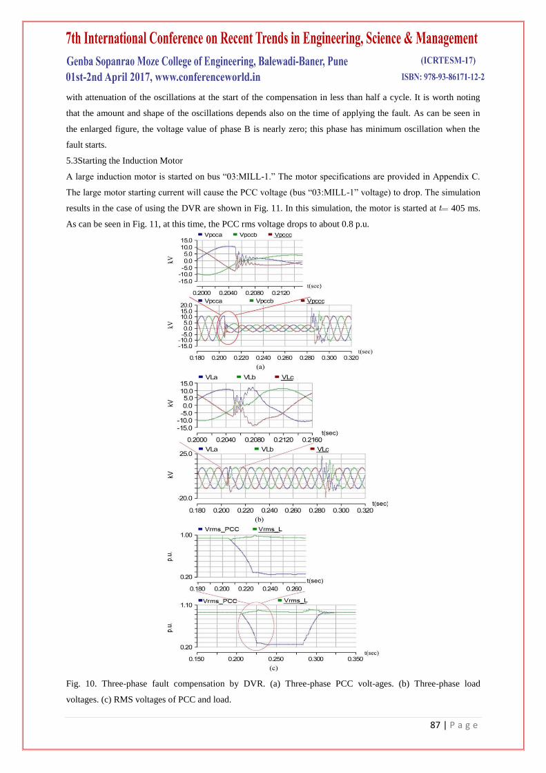
87 | P a g e
with attenuation of the oscillations at the start of the compensation in less than half a cycle. It is worth noting
that the amount and shape of the oscillations depends also on the time of applying the fault. As can be seen in
the enlarged figure, the voltage value of phase B is nearly zero; this phase has minimum oscillation when the
fault starts.
5.3Starting the Induction Motor
A large induction motor is started on bus “03:MILL-1.” The motor specifications are provided in Appendix C.
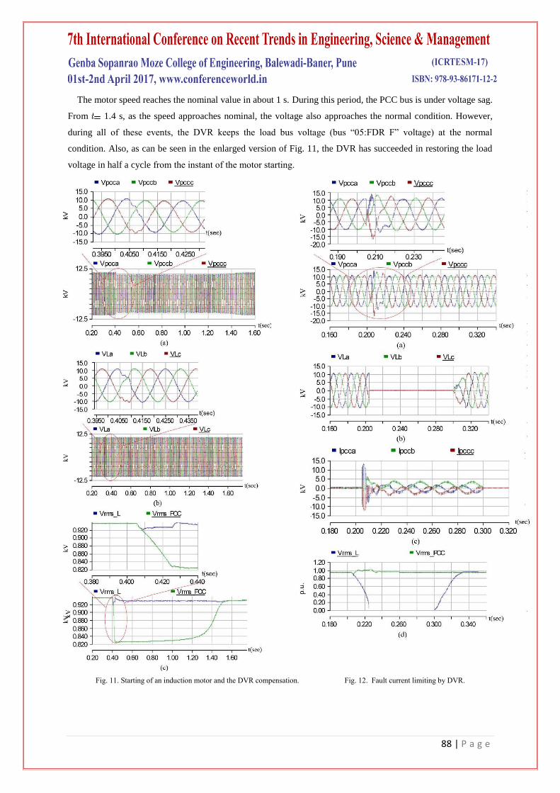
The large motor starting current will cause the PCC voltage (bus “03:MILL-1” voltage) to drop. The simulation
results in the case of using the DVR are shown in Fig. 11. In this simulation, the motor is started at 405 ms.
As can be seen in Fig. 11, at this time, the PCC rms voltage drops to about 0.8 p.u.
Fig. 10. Three-phase fault compensation by DVR. (a) Three-phase PCC volt-ages. (b) Three-phase load
voltages. (c) RMS voltages of PCC and load.
88 | P a g e
The motor speed reaches the nominal value in about 1 s. During this period, the PCC bus is under voltage sag.
From 1.4 s, as the speed approaches nominal, the voltage also approaches the normal condition. However,
during all of these events, the DVR keeps the load bus voltage (bus “05:FDR F” voltage) at the normal
condition. Also, as can be seen in the enlarged version of Fig. 11, the DVR has succeeded in restoring the load
voltage in half a cycle from the instant of the motor starting.
Fig. 11. Starting of an induction motor and the DVR compensation. Fig. 12. Fault current limiting by DVR.
89 | P a g e
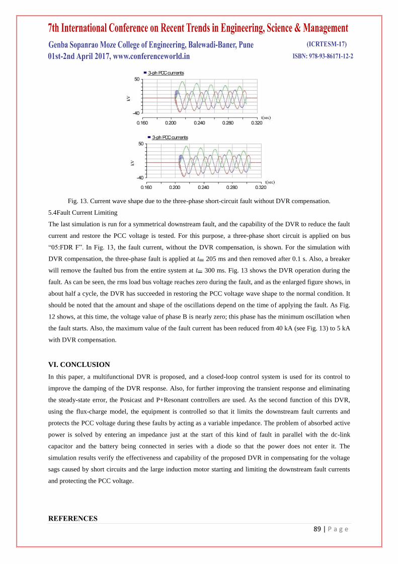
Fig. 13. Current wave shape due to the three-phase short-circuit fault without DVR compensation.
5.4Fault Current Limiting
The last simulation is run for a symmetrical downstream fault, and the capability of the DVR to reduce the fault
current and restore the PCC voltage is tested. For this purpose, a three-phase short circuit is applied on bus
“05:FDR F”. In Fig. 13, the fault current, without the DVR compensation, is shown. For the simulation with
DVR compensation, the three-phase fault is applied at 205 ms and then removed after 0.1 s. Also, a breaker
will remove the faulted bus from the entire system at 300 ms. Fig. 13 shows the DVR operation during the
fault. As can be seen, the rms load bus voltage reaches zero during the fault, and as the enlarged figure shows, in
about half a cycle, the DVR has succeeded in restoring the PCC voltage wave shape to the normal condition. It
should be noted that the amount and shape of the oscillations depend on the time of applying the fault. As Fig.
12 shows, at this time, the voltage value of phase B is nearly zero; this phase has the minimum oscillation when
the fault starts. Also, the maximum value of the fault current has been reduced from 40 kA (see Fig. 13) to 5 kA
with DVR compensation.
VI. CONCLUSION
In this paper, a multifunctional DVR is proposed, and a closed-loop control system is used for its control to
improve the damping of the DVR response. Also, for further improving the transient response and eliminating
the steady-state error, the Posicast and P+Resonant controllers are used. As the second function of this DVR,
using the flux-charge model, the equipment is controlled so that it limits the downstream fault currents and
protects the PCC voltage during these faults by acting as a variable impedance. The problem of absorbed active
power is solved by entering an impedance just at the start of this kind of fault in parallel with the dc-link
capacitor and the battery being connected in series with a diode so that the power does not enter it. The
simulation results verify the effectiveness and capability of the proposed DVR in compensating for the voltage
sags caused by short circuits and the large induction motor starting and limiting the downstream fault currents
and protecting the PCC voltage.
REFERENCES
90 | P a g e
1. J. A. Martinez and J. Martin-Arnedo, “Voltage sag studies in distribution networks-part II: Voltage sag
assessment,” IEEE Trans. Power Del., vol. 21, no. 3, pp. 1679–1688, Jul. 2006.
2. J. A. Martinez and J. M. Arnedo, “Voltage sag studies in distribution networks- part I: System
modeling,” IEEE Trans. Power Del., vol. 21, no. 3, pp. 338–345, Jul. 2006.
3. P. Hcine and M. Khronen, “Voltage sag distribution caused by power system faults,” IEEE Trans.
Power Syst., vol. 18, no. 4, pp. 1367–1373, Nov. 2003.
4. S. Choi, B. H. Li, and D. M. Vilathgamuwa, “Dynamic voltage restoration with minimum energy
injection,” IEEE Trans. Power Syst., vol. 15, no. 1, pp. 51–57, Feb. 2000.
5. C. Fitzer, M. Barnes, and P. Green, “Voltage sag detection technique for a dynamic voltage restore,”
IEEE Trans. Ind. Appl., vol. 2, no. 1, pp. 203–212, Jan./Feb. 2004.
6. C. Benachaiba and B. Ferdi, “Voltage quality improvement using DVR,” Electt. Power Qual.
Utilisation, Journal, vol. XIV, no. 1, 2008.
7. D. M. Vilathgamuwa, H. M. Wijekoon, and S. S. Choi, “A novel technique to compensate voltage sags
in multiline distribution system the interline dynamic voltage restorer,” IEEE Trans. Ind. Electron., vol.
53, no. 5, pp. 1603–1611, Oct. 2006.
8. J. G. Nielsen, M. Newman, H. Nielsen, and F. Blaabjerg, “Control and testing of a dynamic voltage
restorer (DVR) at medium voltage level,” IEEE Trans. Power Electron., vol. 19, no. 3, pp. 806–813,
May 2004.
9. M. J. Newman, D. G. Holmes, J. G. Nielsen, and F. Blaabjerg, “A dynamic voltage restorer (DVR) with
selective harmonic compensation at medium voltage level,” IEEE Trans. Ind. Appl., vol. 41, no. 6, pp.
1744–1753, Nov./Dec. 2005.
10. A. K. Jindal, A. Ghosh, and A. Joshi, “Critical load bus voltage control using DVR under system
frequency variation,” Elect. Power Syst. Res., vol. 78, no. 2, pp. 255–263, Feb. 2008.
11. Y. W. Li, D. M. Vilathgamuwa, P. C. Loh, and F. Blaabjerg, “A dual-functional medium voltage level
DVR to limit downstream fault cur-rents,” IEEE Trans. Power Electron., vol. 22, no. 4, pp. 1330–1340,
Jul. 2007.
12. P. C. Loh, D. M. Vilathgamuwa, S. K. Tang, and H. L. Long, “Multi-level dynamic voltage restorer,”
IEEE Power Electron. Lett., vol. 2, no. 4, pp. 125–130, Dec. 2004.
13. E. Babaei, M. Farhadi, and M. Sabahi, “Compensation of voltage disturbances in distribution systems
using single-phase dynamic voltage restorer,” Elect. Power Syst. Res., Jul. 2010.
14. C. N.-M. Ho and H. S.-H. Chung, “Implementation and performance evaluation of a fast dynamic
control scheme for capacitor-supported interline DVR,” IEEE Trans Power Electron., vol. 25, no. 8, pp.
1975–1988, Aug. 2010.
15. M. Vilathgamuwa, A. A. D. R. Perera, and S. S. Choi, “Performance improvement of the dynamic
voltage restorer with closed-loop load voltage and current-mode control,” IEEE Trans. Power Electron.,
vol. 17, no. 5, pp. 824–834, Sep. 2002.
16. Y. W. Li, P. C. Loh, F. Blaabjerg, and D. M. Vilathgamuwa, “Investigation and improvement of
transient response of DVR at medium voltage level,” IEEE Trans. Ind. Appl., vol. 43, no. 5, pp. 1309–
1319, Sep./Oct. 2007.
91 | P a g e
17. H. Kim and S. K. Sul, “Compensation voltage control in dynamic voltage restorers by use of feed
forward and state feedback scheme,” IEEE Trans. Power Electron., vol. 20, no. 5, pp. 1169–1177, Sep.
2005.
18. M. I. Marei, E. F. El-Saadany, and M. M. A. Salama, “A new approach to control DVR based on
symmetrical components estimation,” IEEE Trans. Power Del., vol. 22, no. 4, pp. 2017–2024, Oct.
2007.
19. Y. W. Li, D. M. Vilathgamuwa, F. Blaabjerg, and P. C. Loh, “A robust control scheme for medium-
voltage level DVR implementation,” IEEE Trans. Ind. Electron., vol. 54, no. 4, pp. 2249–2261, Aug.
2007.
20. S. A. Saleh, C. R. Moloney, and M. A. Rahman, “Implementation of a dynamic voltage restorer system
based on discrete wavelet transforms,” IEEE Trans. Power Del., vol. 23, no. 4, pp. 2360–2375, Oct.
2008.
21. H. Awad, J. Svensson, and M. Bollen, “Mitigation of unbalanced voltage dips using static series
compensator,” IEEE Trans Power Electron., vol. 19, no. 3, pp. 837–846, May 2004.
22. J. V. Milanovic and Y. Zhang, “Global minimization of financial losses due to voltage sags with FACTS
based devices,” IEEE Trans. Power Del., vol. 25, no. 1, pp. 298–306, Jan. 2010.
23. M. H. Rashid, Power Electronics-Circuits, Devices and Applications, 3rd ed. India: Prentice-Hall of
India, Aug. 2006.
24. M. Vilathgamua, A. A. D. R. Perara, S. S. Choi, and K. J. Tseng, “Control of energy optimized dynamic
voltage restorer,” in Proc. IEEE IECON Conf., San Jose, CA, 1999, vol. 2, pp. 873–878.
25. “Task force on harmonics modeling & simulation (co-author), test systems for harmonics modeling and
simulation,” IEEE Trans. Power Del., vol. 14, no. 2, pp. 579–585, Apr. 1999