analysis, design and development of an automated testing
TRANSCRIPT

Faculdade de Engenharia da Universidade do PortoLicenciatura em Engenharia Informatica e Computacao
Analysis, design and development of an automated testingplatform for a multi-function network appliance
at Critical Software
LEIC curricular internship report, 2006
Rui Andre Augusto Ferreira
Supervisor at University of Porto: Prof. Jorge BarbosaSupervisor at Critical Software: Alexandre Esper
September, 2006


To my family...


Abstract
abstract aqui!

CONTENTS
Contents
Preface vii
Acknowledgements ix
Guide to readers xi
Acronyms xiii
1 Introduction 1
1.1 The company . . . . . . . . . . . . . . . . . . . . . . . . . . . . . . . . . . . . . . . . . . . . . 1
1.1.1 Background . . . . . . . . . . . . . . . . . . . . . . . . . . . . . . . . . . . . . . . . . . 1
1.1.2 Company profile . . . . . . . . . . . . . . . . . . . . . . . . . . . . . . . . . . . . . . . 1
1.1.3 Organization . . . . . . . . . . . . . . . . . . . . . . . . . . . . . . . . . . . . . . . . . 1
1.2 Overview of the product . . . . . . . . . . . . . . . . . . . . . . . . . . . . . . . . . . . . . . . 3
1.2.1 edgeBOX . . . . . . . . . . . . . . . . . . . . . . . . . . . . . . . . . . . . . . . . . . . 3
1.2.2 Items . . . . . . . . . . . . . . . . . . . . . . . . . . . . . . . . . . . . . . . . . . . . . 3
1.3 The internship . . . . . . . . . . . . . . . . . . . . . . . . . . . . . . . . . . . . . . . . . . . . . 3
1.3.1 Global goal . . . . . . . . . . . . . . . . . . . . . . . . . . . . . . . . . . . . . . . . . . 3
1.3.2 Workplace . . . . . . . . . . . . . . . . . . . . . . . . . . . . . . . . . . . . . . . . . . 4
1.3.3 Objectives . . . . . . . . . . . . . . . . . . . . . . . . . . . . . . . . . . . . . . . . . . . 4
1.3.4 Framing of the internship in the product . . . . . . . . . . . . . . . . . . . . . . . . . . . 4
1.3.5 Tasks . . . . . . . . . . . . . . . . . . . . . . . . . . . . . . . . . . . . . . . . . . . . . 4
1.3.6 Planning . . . . . . . . . . . . . . . . . . . . . . . . . . . . . . . . . . . . . . . . . . . 5
2 The product: a network appliance 7
2.1 Introduction . . . . . . . . . . . . . . . . . . . . . . . . . . . . . . . . . . . . . . . . . . . . . . 7
2.1.1 Market opportunity . . . . . . . . . . . . . . . . . . . . . . . . . . . . . . . . . . . . . . 7
2.1.2 Market size . . . . . . . . . . . . . . . . . . . . . . . . . . . . . . . . . . . . . . . . . . 7
2.1.3 The product and the services . . . . . . . . . . . . . . . . . . . . . . . . . . . . . . . . . 8
2.1.4 Business model . . . . . . . . . . . . . . . . . . . . . . . . . . . . . . . . . . . . . . . . 10
2.1.5 Critical Links . . . . . . . . . . . . . . . . . . . . . . . . . . . . . . . . . . . . . . . . . 11
iii
CONTENTS
2.2 Organization . . . . . . . . . . . . . . . . . . . . . . . . . . . . . . . . . . . . . . . . . . . . . . 11
2.2.1 Group organization . . . . . . . . . . . . . . . . . . . . . . . . . . . . . . . . . . . . . . 11
2.2.2 Development model . . . . . . . . . . . . . . . . . . . . . . . . . . . . . . . . . . . . . 11
2.3 Comparison with other products . . . . . . . . . . . . . . . . . . . . . . . . . . . . . . . . . . . 13
2.4 Product architecture . . . . . . . . . . . . . . . . . . . . . . . . . . . . . . . . . . . . . . . . . . 13
2.4.1 The operating system . . . . . . . . . . . . . . . . . . . . . . . . . . . . . . . . . . . . . 13
2.4.2 Packages manager and licences authentication . . . . . . . . . . . . . . . . . . . . . . . . 13
2.4.3 Configuration architecture . . . . . . . . . . . . . . . . . . . . . . . . . . . . . . . . . . 14
2.4.4 Request handling . . . . . . . . . . . . . . . . . . . . . . . . . . . . . . . . . . . . . . . 14
3 The project: automated testing platform 15
3.1 Important concepts on testing . . . . . . . . . . . . . . . . . . . . . . . . . . . . . . . . . . . . . 15
3.2 Problem domain . . . . . . . . . . . . . . . . . . . . . . . . . . . . . . . . . . . . . . . . . . . . 17
3.3 State of the art . . . . . . . . . . . . . . . . . . . . . . . . . . . . . . . . . . . . . . . . . . . . . 17
3.4 Comparison . . . . . . . . . . . . . . . . . . . . . . . . . . . . . . . . . . . . . . . . . . . . . . 19
4 Requirements analysis 21
4.1 Automated testing platform definition . . . . . . . . . . . . . . . . . . . . . . . . . . . . . . . . 21
4.2 Objectives . . . . . . . . . . . . . . . . . . . . . . . . . . . . . . . . . . . . . . . . . . . . . . . 21
4.3 User roles and responsibilities . . . . . . . . . . . . . . . . . . . . . . . . . . . . . . . . . . . . 22
4.4 Interactions with other systems . . . . . . . . . . . . . . . . . . . . . . . . . . . . . . . . . . . . 22
4.5 Functional requirements . . . . . . . . . . . . . . . . . . . . . . . . . . . . . . . . . . . . . . . 22
4.5.1 Use cases . . . . . . . . . . . . . . . . . . . . . . . . . . . . . . . . . . . . . . . . . . . 22
4.5.2 Example automated test implementations required . . . . . . . . . . . . . . . . . . . . . 25
4.5.3 Usage scenarios . . . . . . . . . . . . . . . . . . . . . . . . . . . . . . . . . . . . . . . . 25
4.6 Non-functional requirements . . . . . . . . . . . . . . . . . . . . . . . . . . . . . . . . . . . . . 26
4.6.1 Usability . . . . . . . . . . . . . . . . . . . . . . . . . . . . . . . . . . . . . . . . . . . 26
4.6.2 Time requirements . . . . . . . . . . . . . . . . . . . . . . . . . . . . . . . . . . . . . . 26
4.6.3 Architecture requirements . . . . . . . . . . . . . . . . . . . . . . . . . . . . . . . . . . 26
4.6.4 Hardware considerations . . . . . . . . . . . . . . . . . . . . . . . . . . . . . . . . . . . 26
4.7 User interface prototypes . . . . . . . . . . . . . . . . . . . . . . . . . . . . . . . . . . . . . . . 26
4.8 Scope . . . . . . . . . . . . . . . . . . . . . . . . . . . . . . . . . . . . . . . . . . . . . . . . . 26
5 Architecture and detailed design 27
5.1 Design standards . . . . . . . . . . . . . . . . . . . . . . . . . . . . . . . . . . . . . . . . . . . 27
5.2 Integration in the system . . . . . . . . . . . . . . . . . . . . . . . . . . . . . . . . . . . . . . . 27
5.3 System overview . . . . . . . . . . . . . . . . . . . . . . . . . . . . . . . . . . . . . . . . . . . 28
5.3.1 Architecture justification . . . . . . . . . . . . . . . . . . . . . . . . . . . . . . . . . . . 29
5.3.2 Design Patterns . . . . . . . . . . . . . . . . . . . . . . . . . . . . . . . . . . . . . . . . 30
iv

CONTENTS
5.4 Data model . . . . . . . . . . . . . . . . . . . . . . . . . . . . . . . . . . . . . . . . . . . . . . 31
5.4.1 Class model . . . . . . . . . . . . . . . . . . . . . . . . . . . . . . . . . . . . . . . . . . 31
5.4.2 Physical model . . . . . . . . . . . . . . . . . . . . . . . . . . . . . . . . . . . . . . . . 31
5.5 System decomposition . . . . . . . . . . . . . . . . . . . . . . . . . . . . . . . . . . . . . . . . 33
5.5.1 Core module . . . . . . . . . . . . . . . . . . . . . . . . . . . . . . . . . . . . . . . . . 33
5.5.2 User interface . . . . . . . . . . . . . . . . . . . . . . . . . . . . . . . . . . . . . . . . . 34
5.5.3 Automated test case . . . . . . . . . . . . . . . . . . . . . . . . . . . . . . . . . . . . . 35
6 Testing and software quality assurance 37
6.1 Scope of testing . . . . . . . . . . . . . . . . . . . . . . . . . . . . . . . . . . . . . . . . . . . . 37
6.2 Schedule . . . . . . . . . . . . . . . . . . . . . . . . . . . . . . . . . . . . . . . . . . . . . . . . 37
6.3 Approach . . . . . . . . . . . . . . . . . . . . . . . . . . . . . . . . . . . . . . . . . . . . . . . 37
6.4 Test cases . . . . . . . . . . . . . . . . . . . . . . . . . . . . . . . . . . . . . . . . . . . . . . . 38
6.5 Unit testing . . . . . . . . . . . . . . . . . . . . . . . . . . . . . . . . . . . . . . . . . . . . . . 40
6.6 Code inspections . . . . . . . . . . . . . . . . . . . . . . . . . . . . . . . . . . . . . . . . . . . 40
6.7 Beta testing . . . . . . . . . . . . . . . . . . . . . . . . . . . . . . . . . . . . . . . . . . . . . . 41
7 Documentation 43
7.1 Approach to documentation . . . . . . . . . . . . . . . . . . . . . . . . . . . . . . . . . . . . . . 43
7.2 User manual and application tour . . . . . . . . . . . . . . . . . . . . . . . . . . . . . . . . . . . 43
7.2.1 Application front page . . . . . . . . . . . . . . . . . . . . . . . . . . . . . . . . . . . . 43
7.2.2 Manage tests . . . . . . . . . . . . . . . . . . . . . . . . . . . . . . . . . . . . . . . . . 44
7.2.3 Manage areas . . . . . . . . . . . . . . . . . . . . . . . . . . . . . . . . . . . . . . . . . 44
7.2.4 Manage campaigns . . . . . . . . . . . . . . . . . . . . . . . . . . . . . . . . . . . . . . 46
7.2.5 List and view executions . . . . . . . . . . . . . . . . . . . . . . . . . . . . . . . . . . . 46
7.2.6 View statistics . . . . . . . . . . . . . . . . . . . . . . . . . . . . . . . . . . . . . . . . 49
7.3 Installation manual . . . . . . . . . . . . . . . . . . . . . . . . . . . . . . . . . . . . . . . . . . 50
8 Final considerations and results analysis 51
8.1 Automated testing platform results . . . . . . . . . . . . . . . . . . . . . . . . . . . . . . . . . . 51
8.1.1 Improvements . . . . . . . . . . . . . . . . . . . . . . . . . . . . . . . . . . . . . . . . . 51
8.2 Automated tests results . . . . . . . . . . . . . . . . . . . . . . . . . . . . . . . . . . . . . . . . 51
8.3 Internship considerations . . . . . . . . . . . . . . . . . . . . . . . . . . . . . . . . . . . . . . . 52
A Gant chart 55
B User interface prototypes 59
C Edgebox Fleur 61
D CD 65
v

LIST OF FIGURES
List of Figures
1.1 Offices . . . . . . . . . . . . . . . . . . . . . . . . . . . . . . . . . . . . . . . . . . . . . . . . . 2
1.2 Certifications . . . . . . . . . . . . . . . . . . . . . . . . . . . . . . . . . . . . . . . . . . . . . 2
2.1 Worldwide business gateway revenue forecast (�M) 2005-2010 . . . . . . . . . . . . . . . . . . 8
2.2 European managed services revenue forecast (�M) 2005-2010 . . . . . . . . . . . . . . . . . . . 8
2.3 Telecom revenue (�B) 1999-2003 . . . . . . . . . . . . . . . . . . . . . . . . . . . . . . . . . . 8
2.4 Features . . . . . . . . . . . . . . . . . . . . . . . . . . . . . . . . . . . . . . . . . . . . . . . . 9
2.5 Business relations . . . . . . . . . . . . . . . . . . . . . . . . . . . . . . . . . . . . . . . . . . . 10
2.6 Target markets . . . . . . . . . . . . . . . . . . . . . . . . . . . . . . . . . . . . . . . . . . . . . 10
2.7 Group organization . . . . . . . . . . . . . . . . . . . . . . . . . . . . . . . . . . . . . . . . . . 11
2.8 Group meetings . . . . . . . . . . . . . . . . . . . . . . . . . . . . . . . . . . . . . . . . . . . . 12
2.9 Coordination tools . . . . . . . . . . . . . . . . . . . . . . . . . . . . . . . . . . . . . . . . . . 12
2.10 Product comparison . . . . . . . . . . . . . . . . . . . . . . . . . . . . . . . . . . . . . . . . . . 13
2.11 Architecture and flow of the configuration system. . . . . . . . . . . . . . . . . . . . . . . . . . . 14
3.1 Conceptual domain model . . . . . . . . . . . . . . . . . . . . . . . . . . . . . . . . . . . . . . 17
4.1 Actors . . . . . . . . . . . . . . . . . . . . . . . . . . . . . . . . . . . . . . . . . . . . . . . . . 22
4.2 Tester’s use cases . . . . . . . . . . . . . . . . . . . . . . . . . . . . . . . . . . . . . . . . . . . 23
4.3 Administrator’s use cases . . . . . . . . . . . . . . . . . . . . . . . . . . . . . . . . . . . . . . . 24
4.4 Activity diagram with the most common scenarios . . . . . . . . . . . . . . . . . . . . . . . . . . 25
5.1 ATP integration with edgeBOX components . . . . . . . . . . . . . . . . . . . . . . . . . . . . . 28
5.2 ATP decomposition in high-level components . . . . . . . . . . . . . . . . . . . . . . . . . . . . 29
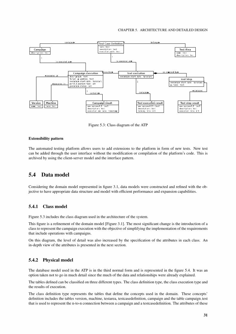
5.3 Class diagram of the ATP . . . . . . . . . . . . . . . . . . . . . . . . . . . . . . . . . . . . . . . 31
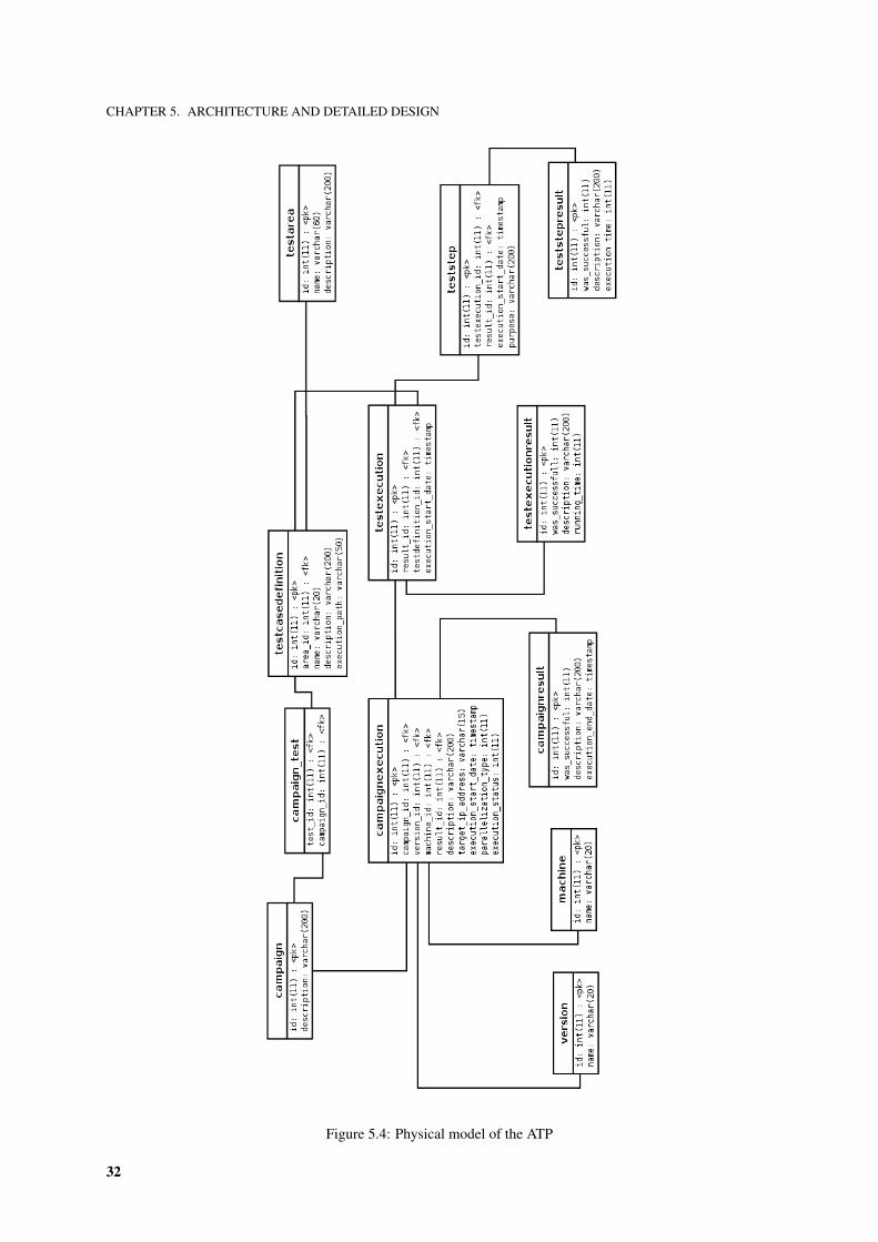
5.4 Physical model of the ATP . . . . . . . . . . . . . . . . . . . . . . . . . . . . . . . . . . . . . . 32
5.5 Components of the core module . . . . . . . . . . . . . . . . . . . . . . . . . . . . . . . . . . . 33
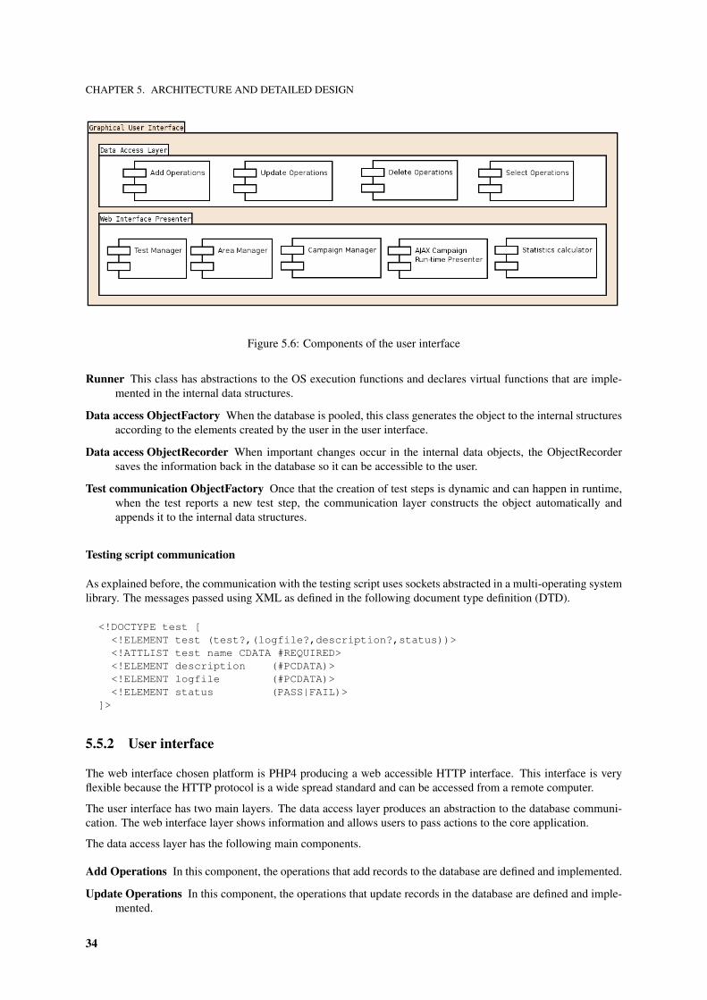
5.6 Components of the user interface . . . . . . . . . . . . . . . . . . . . . . . . . . . . . . . . . . . 34
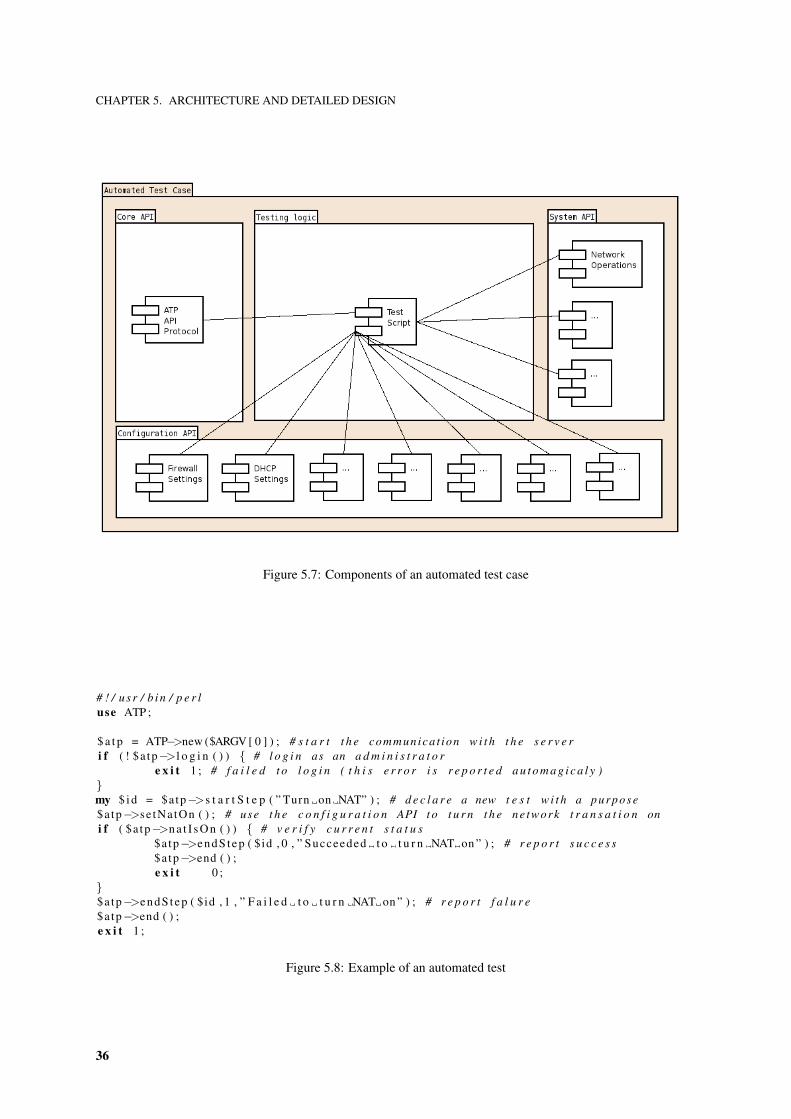
5.7 Components of an automated test case . . . . . . . . . . . . . . . . . . . . . . . . . . . . . . . . 36
5.8 Example of an automated test . . . . . . . . . . . . . . . . . . . . . . . . . . . . . . . . . . . . . 36
vii

LIST OF FIGURES
7.1 Main page - interface . . . . . . . . . . . . . . . . . . . . . . . . . . . . . . . . . . . . . . . . . 44
7.2 Manage tests - interfaces . . . . . . . . . . . . . . . . . . . . . . . . . . . . . . . . . . . . . . . 45
7.3 Manage areas - interfaces . . . . . . . . . . . . . . . . . . . . . . . . . . . . . . . . . . . . . . . 46
7.4 Manage campaigns - interfaces . . . . . . . . . . . . . . . . . . . . . . . . . . . . . . . . . . . . 47
7.5 View executions- interfaces . . . . . . . . . . . . . . . . . . . . . . . . . . . . . . . . . . . . . . 48
7.6 View statistics - interfaces . . . . . . . . . . . . . . . . . . . . . . . . . . . . . . . . . . . . . . 49
B.1 User interface prototypes . . . . . . . . . . . . . . . . . . . . . . . . . . . . . . . . . . . . . . . 60
viii

Preface
This document intents do describe the work developed at Critical Software between March, 2006 and August,2006 in the scope of the internship project ”Analysis, design and development of an automated testing platformfor a multi-function network appliance” by Rui Ferreira.
The language of choice was English since it is the standard language for the production of documentation atCritical Software and it allows this document to reach a wider audience.
The target audience is the jury appointed to the evaluation of the internship but this can be considered an introduc-tion to the automated testing platform described here or even to automated testing in general.
The project and all associated information was developed and producted under contractual agreement amongCritical Software, S.A and University of Porto. Therefore the access is restricted according to the defined in theinternship protocol and the non-disclosure agreement signed.
ix

Acknowledgements
No one who achieves success does so without acknowledging the help of others.The wise and confident acknowledge this help with gratitude.
– Alfred Whitehead
My acknowledgement to Critical Software S.A for the opportunity offered of a great internship, the warm welcomeand outstanding work conditions.
To my university tutor in the Engineering University of the University of Porto, Jorge Barbosa for his constantavailability and support.
To my company tutor in Critical Software S.A, Alexandre Esper for his successful efforts for my integration withinthe team, the development of a interesting project and above all, the opportunity of learning.
To all Critical Software workers and interns for, with no exceptions their companionship and support. A specialthanks to Nelson Vale, Bruno Ramos, Andre Barbosa, Andre Lemos, Helder Sousa, Goncalo Jesus, ClaudiaSerafim and Rui Portugal.
Being this the end of an important cycle in my life and the beginning of a new one, I thank my family and myfriends who always helped me in the course of my life.
xi

Guide to readers
It is well to read everything of something, and something of everything.– Lord Henry P. Brougham
This documents tries to describe the work done at Critical Software between March and August of 2006 in achronological order and trying to give insights of the software development stages.
Chapter 1, Introduction, starts by presenting the company Critical Software where the internship occurred. Theproduct to which the software developed is applied is also introduced in this chapter. The introduction is finishedby presenting the internship goals, tasks and planning.
Chapter 2, The product: a network appliance, includes information about the edgeBOX. A business overview, theorganization, the market competition and product architecture are the topics explored.
Chapter 3, The project: automated testing platform, introduces the area of testing by giving an overview of themodern concepts in automated testing, the domain of the problem and the state of the art.
Chapter 4, Requirements analysis, specifies the requirements for the automated testing application to be developedand tries to provide the reader information to understand the application by the means of use cases and usagescenarios.
Chapter 5, Architecture and detailed design, explains the architecture and technologies by reviewing in detail thesystem, each of its modules and the data structures used.
Chapter 6, Testing and software quality assurance, sums up the testing done to the application by including asummary of the test cases specified and by explaining the unit testing, code inspection and beta testing approaches.
Chapter 7, Documentation, describes the approach and tools used to document the system and provides the readerwith manuals to use and install the platform. These manuals can be used as tour of the application and showclearly why it is useful.
This document ends with chapter 8, Final considerations and results analysis, where a review of the work producedand results archived is presented.
Some chapters refer to external information that is available in appendix.
xiii

Acronyms
CSW Critical Software
SME Small Medium Enterprises
SMB Small Medium Business
EBO Enterprise Branch Offices
CEO Chief Executive Officer
CFO Chief Financial Officer
ARPU Average Revenue Per User
POTS Plain Old Telephone Service
VoIP Voice over Internet Protocol
IT Information Technology
CPE Costumer Premises Equipment
NOC Network Operations Center
COTS Commercial Off-The-Shelf
VAR Value-Added Reseller
CRM Costumer Relationship Management
eOS edgeBOX Operating System
LFS Linux From Scratch
CLI Command Line Interface
PDP Policy Decision Point
PEP Policy Enforcement Point
IPC Inter Process Communication
ATP Automated Testing Platform
GUI Graphical User Interface
xv


CHAPTER 1. INTRODUCTION
Chapter 1
Introduction
1.1 The company
1.1.1 Background
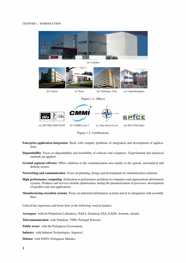
Critical Software (CSW) supplies solutions, services and technologies for companies’ information systems, an-swering to the necessities of several markets as telecommunication, public sector, industry and the aerospace anddefense sectors. The company was founded in 1998 and currently employs more than 140 people in their officesin Coimbra, Lisboa, Porto in Portugal, Southapton in the United Kingdom and San Jose, California in the USA[Figure 1.1].
Critical Links is a wholly owned subsidiary of Critical Software that develops and markets edgeBOX, a multi-function server appliance or ”business gateway” targeted at Small Medium Enterprises (SME) and EnterpriseBranch Offices (EBO).
The management and product team behind Critical Links builds on the success and reputation of the parent com-pany Critical Software and leverages its technical talent and market experience.
1.1.2 Company profile
Critical Software success is based upon the use of high quality levels and technological innovation as agents inthe introduction competitive advantages in clients and partners. The company currently commercializes in theinternational market innovative products in areas as dependability and high performance computing.
Accordingly, the company invests heavily on R&D (around 12% of total revenues) as well as in its quality systemthat have been certified to demanding international standards.
Critical is flexible and agile, and has proved that it can respond quickly and efficiently to customers’ rapidlychanging business environments. From its foundation in 1998, Critical has received several awards and distinc-tions. Among them, it has been listed in Business-Week’s Top 300 fastest growing companies and has beenawarded by INSEAD for Management excellence.
Critical has a strong international customer base spread across Europe, the US, and Asia in the Telecom, Aerospaceand Defense Sectors. The experience acquired working with customers in these sectors provides extensive businessknowledge that Critical Links is using in developing innovative products and services such as edgeBOX andITEMS.
1.1.3 Organization
One way of describing the positioning and operations of Critical Software is to look at its horizontal organization.
1
CHAPTER 1. INTRODUCTION
(a) Coimbra
(b) Lisboa (c) Porto (d) California, USA (e) United Kingdom
Figure 1.1: Offices
(a) ISO 9001:2000 TickIT (b) CMMI Level 3 (c) Nato Secret Level (d) ISO 15504 Spice
Figure 1.2: Certifications
Enterprise application integration Deals with complex problems of integration and development of applica-tions.
Dependability Focus on dependability and trustability of software and computers. Experimental and analyticalmethods are applied.
Ground segment software Offers solutions to the communication area mainly to the spacial, aeronautical anddefense sectors
Networking and communication Focus on planning, design and development of communication solutions.
High performance computing Dedication to performance problems in companies and organizations informationsystems. Products and services include optimization, tuning the parametrization of processes, developmentof parallel code and applications
Manufacturing execution systems Focus on industrial information systems and in its integration with assemblylines.
Critical has experience and know-how in the following vertical markets.
Aerospace with Jet Propulsion Laboratory, NASA, Eumetsat, ESA, EADS, Astrium, Alcatel.
Telecommunication with Vodafone, TMN, Portugal Telecom.
Public sector with the Portuguese Government.
Industry with Infineon Technologies, Soporcel.
Defense with NATO, Portuguese Marines.
2

CHAPTER 1. INTRODUCTION
The administration is composed by:
Goncalo Quadros Chief Executive Officer (CEO)
Joao Carreira VP business development
Diamantino Costa VP business development
Abel Pinto VP finance and human resources
Pedro Murtinho Chief Financial Officer (CFO)
Rui Cordeiro Engineering director
1.2 Overview of the product
1.2.1 edgeBOX
Installed at the edge of the WAN and the LAN, the edgeBOX delivers high-speed internet access and enables awealth of managed services out of a single, integrated, secure, flexible, reliable and easy-to-use platform.
The edgeBOX replaces 5-8 traditional costumer premise equipments.
Router Forwards data packets across a network toward their destinations.
Security Controls traffic between different zones of trust.
VoIP, IP-PBX Allows voice over internet protocol with call switching.
WiFi Access Point Offers a wireless local area network access point.
Network Access Controller Enforces security policy and restrict prohibited traffic types.
Quality of Service Offers bandwidth constraining by class of user.
Storage Allows users to create personal network storage, public storage and group storage.
Collaboration Includes mail server, webmail, web server, CMS server.
The edgeBOX uses community open source software but brings the ease of use of professional software by offeringan user friendly and ”idiot proof” web interface. It ends with manual edition of configuration files but still hasthe flexibility to be used in small/medium enterprises or enterprise branch offices. Another advantage is that it iscertified for specific hardware appropriate to different company sizes.
A business, organizational and technical analysis of the product and its organization can be found in chapter 2.
1.2.2 Items
Items is a tool for the batch configuration of several edgeBOX. This tool makes business sense to companies thatwant to offer edgeBOX’s services as a added value service to their core products and services.
Once again, in chapter 2 more information can be found on this topic.
1.3 The internship
1.3.1 Global goal
The global goal of the internship is the development and integration of open-source based technologies and toolsto the construction of an automated testing platform for edgeBOX’s testbed.
3
CHAPTER 1. INTRODUCTION
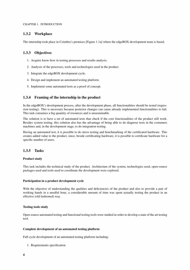
1.3.2 Workplace
The internship took place in Coimbra’s premises [Figure 1.1a] where the edgeBOX development team is based.
1.3.3 Objectives
1. Acquire know-how in testing processes and results analysis.
2. Analysis of the processes, tools and technologies used in the product.
3. Integrate the edgeBOX development cycle.
4. Design and implement an automated testing platform.
5. Implement some automated tests as a proof of concept.
1.3.4 Framing of the internship in the product
In the edgeBOX’s development process, after the development phase, all functionalities should be tested (regres-sion testing). This is necessary because posterior changes can cause already implemented functionalities to fail.This task consumes a big quantity of resources and is unsustainable.
The solution is to have a set of automated tests that check if the core functionalities of the product still work.Besides system testing, this solution also has the advantage of being able to do diagnose tests in the costumersmachines and, in the development stage, to do integration testing.
Having an automated test, it is possible to do stress testing and benchmarking of the certificated hardware. Thiscreates added value to the product, since, beside certificating hardware, it is possible to certificate hardware for aspecific number of users.
1.3.5 Tasks
Product study
This task includes the technical study of the product. Architecture of the system, technologies used, open-sourcepackages used and tools used to coordinate the development were explored.
Participation in a product development cycle
With the objective of understanding the qualities and deficiencies of the product and also to provide a pair ofworking hands in a needful hour, a considerable amount of time was spent actually testing the product in aneffective (old fashioned) way.
Testing tools study
Open source automated testing and functional testing tools were studied in order to develop a state of the art testingtool.
Complete development of an automated testing platform
Full cycle development of an automated testing platform including:
1. Requirements specification
4
CHAPTER 1. INTRODUCTION
2. Architecture definition
3. Prototyping
4. Complete implementation
5. Testing
6. Documentation
Development of some automated tests
To prove that the platform is functional and useful some automated tests were developed and the results wereanalyzed.
1.3.6 Planning
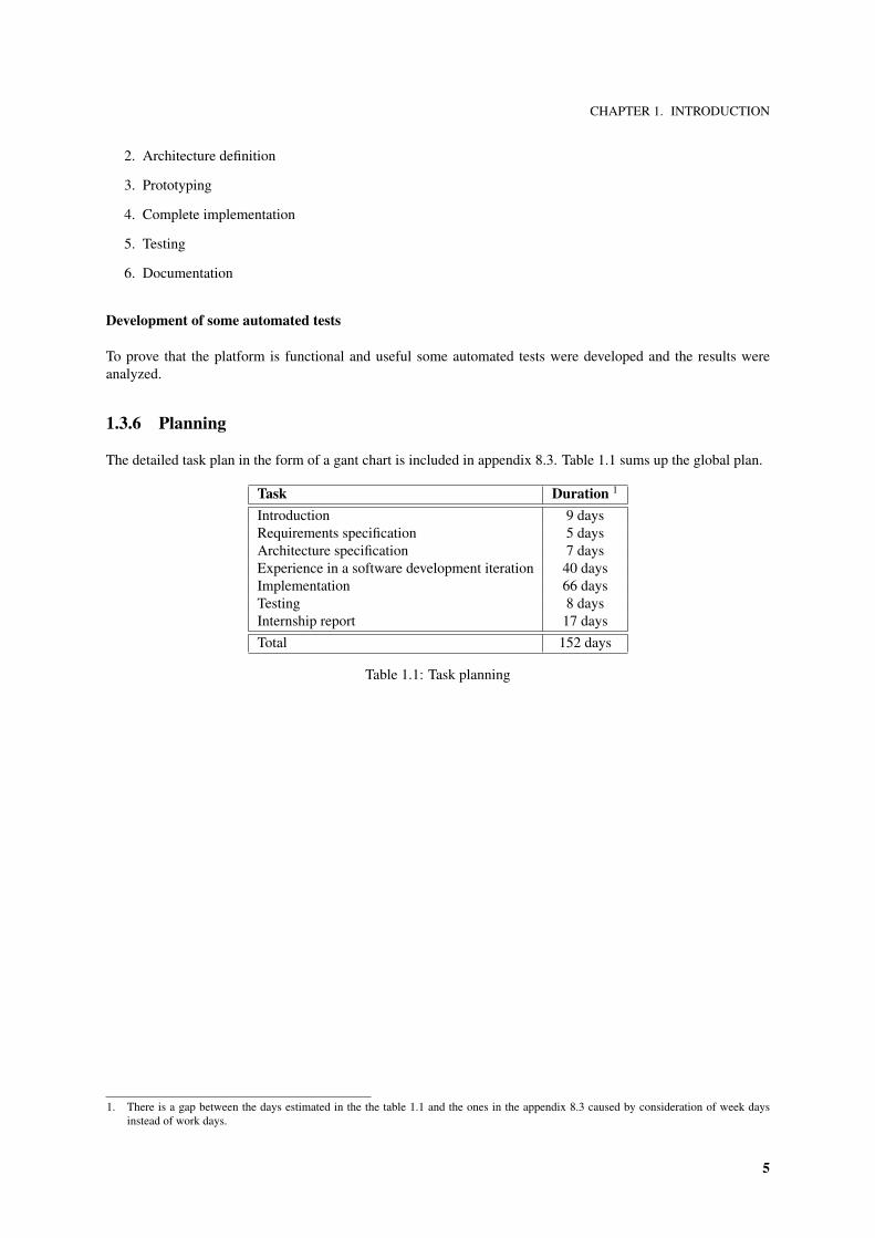
The detailed task plan in the form of a gant chart is included in appendix 8.3. Table 1.1 sums up the global plan.
Task Duration 1
Introduction 9 daysRequirements specification 5 daysArchitecture specification 7 daysExperience in a software development iteration 40 daysImplementation 66 daysTesting 8 daysInternship report 17 daysTotal 152 days
Table 1.1: Task planning
1. There is a gap between the days estimated in the the table 1.1 and the ones in the appendix 8.3 caused by consideration of week daysinstead of work days.
5

CHAPTER 2. THE PRODUCT: A NETWORK APPLIANCE
Chapter 2
The product: a network appliance
How many IT services can you squeeze into a box for an SMB? Juniper Networks, Cisco Systems, and 3Com havecome up with some for security and Avaya, Alcatel, Nortel, and Siemens for communications. But how about 50
applications that do everything from being a wireless router; has web, e-mail and DNS/DHCP services; IPtelephony (with Asterisk IP PBX); and firewall with VPN, authentication and anti-spam/anti-virus capabilities?
The edgeBOX is what they call it and the company called Critical Software put it together.– Benjamin Koe in Security Tech Planet
2.1 Introduction
2.1.1 Market opportunity
The market opportunity appears from the latest movements in service providers and from the new needs fromSMEs and EBO.
Service providers
In the last few years, broadband prices have suffered a significant decrease. Service providers need to increase theAverage Revenue Per User (ARPU) through the sale of value added services. Considering the market dimensions,service providers need to easily and effectively manage these value added services in a wide number of clients.
Most broadband providers also provide Plain Old Telephone Service (POTS), and with the market shifting toVoice over Internet Protocol (VoIP) it is easier for them to keep the clients since they provide a similar servicesince long. Nevertheless, Skype, Microsoft and Google are big names the will have a word to say in this market.
SMEs and EBOs
With typically low Information Technology (IT) budgets and lack of specialized IT know-how, SMEs and EBOsneed to have access to proper network services. The use of the IT infrastructure to compete, the need for security,the growing number of home-workers and the market shift to VoIP will be key instruments and challenges to thefuture of the world’s companies.
2.1.2 Market size
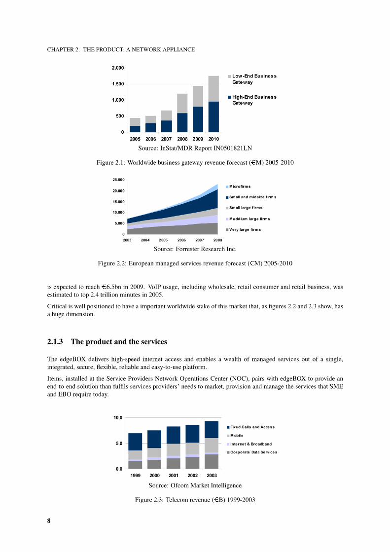
InSTAT/MDR estimates that the business gateways market will be worth �1.6bn by 2010 [Figure 2.1]. Worldwidebroadband Costumer Premises Equipment (CPE) revenues grew 123% last year to reach �4.9bn in 2005 and it
7
CHAPTER 2. THE PRODUCT: A NETWORK APPLIANCE
Source: InStat/MDR Report IN0501821LN
Figure 2.1: Worldwide business gateway revenue forecast (�M) 2005-2010
Source: Forrester Research Inc.
Figure 2.2: European managed services revenue forecast (�M) 2005-2010
is expected to reach �6.5bn in 2009. VoIP usage, including wholesale, retail consumer and retail business, wasestimated to top 2.4 trillion minutes in 2005.
Critical is well positioned to have a important worldwide stake of this market that, as figures 2.2 and 2.3 show, hasa huge dimension.
2.1.3 The product and the services
The edgeBOX delivers high-speed internet access and enables a wealth of managed services out of a single,integrated, secure, flexible, reliable and easy-to-use platform.
Items, installed at the Service Providers Network Operations Center (NOC), pairs with edgeBOX to provide anend-to-end solution than fulfils services providers’ needs to market, provision and manage the services that SMEand EBO require today.
Source: Ofcom Market Intelligence
Figure 2.3: Telecom revenue (�B) 1999-2003
8
CHAPTER 2. THE PRODUCT: A NETWORK APPLIANCE
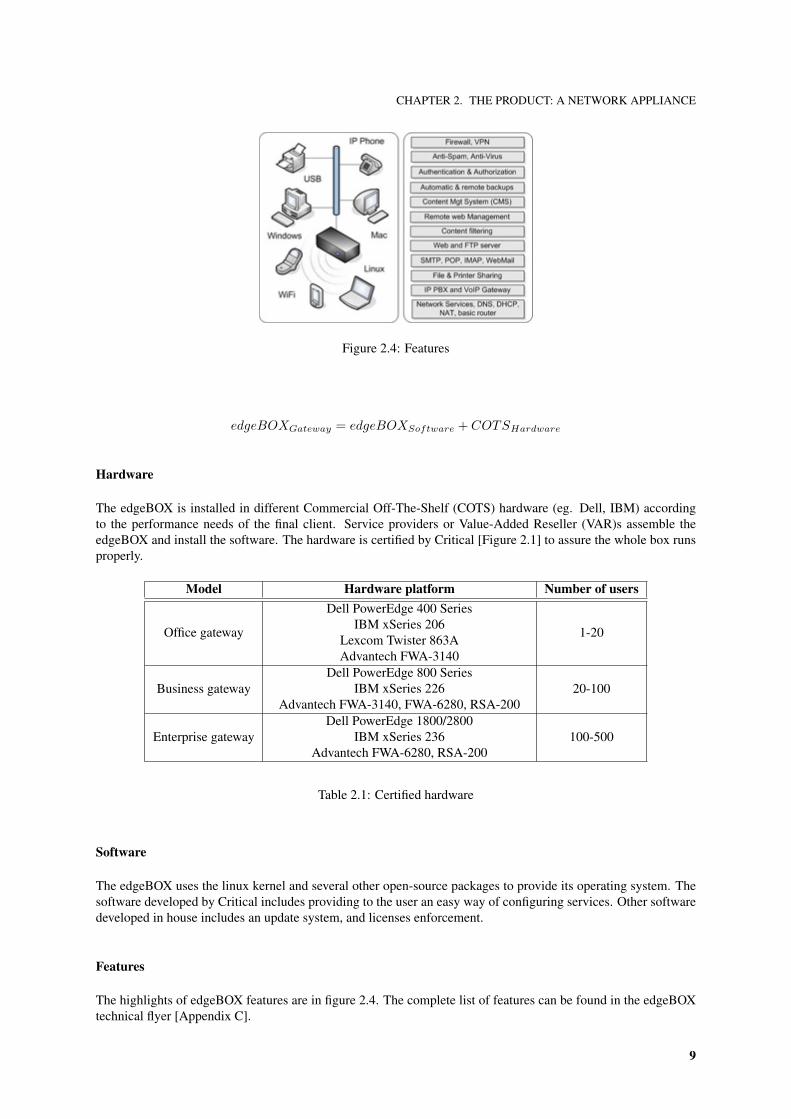
Figure 2.4: Features
edgeBOXGateway = edgeBOXSoftware + COTSHardware
Hardware
The edgeBOX is installed in different Commercial Off-The-Shelf (COTS) hardware (eg. Dell, IBM) accordingto the performance needs of the final client. Service providers or Value-Added Reseller (VAR)s assemble theedgeBOX and install the software. The hardware is certified by Critical [Figure 2.1] to assure the whole box runsproperly.
Model Hardware platform Number of users
Office gateway
Dell PowerEdge 400 SeriesIBM xSeries 206
Lexcom Twister 863AAdvantech FWA-3140
1-20
Business gatewayDell PowerEdge 800 Series
IBM xSeries 226Advantech FWA-3140, FWA-6280, RSA-200
20-100
Enterprise gatewayDell PowerEdge 1800/2800
IBM xSeries 236Advantech FWA-6280, RSA-200
100-500
Table 2.1: Certified hardware
Software
The edgeBOX uses the linux kernel and several other open-source packages to provide its operating system. Thesoftware developed by Critical includes providing to the user an easy way of configuring services. Other softwaredeveloped in house includes an update system, and licenses enforcement.
Features
The highlights of edgeBOX features are in figure 2.4. The complete list of features can be found in the edgeBOXtechnical flyer [Appendix C].
9
CHAPTER 2. THE PRODUCT: A NETWORK APPLIANCE
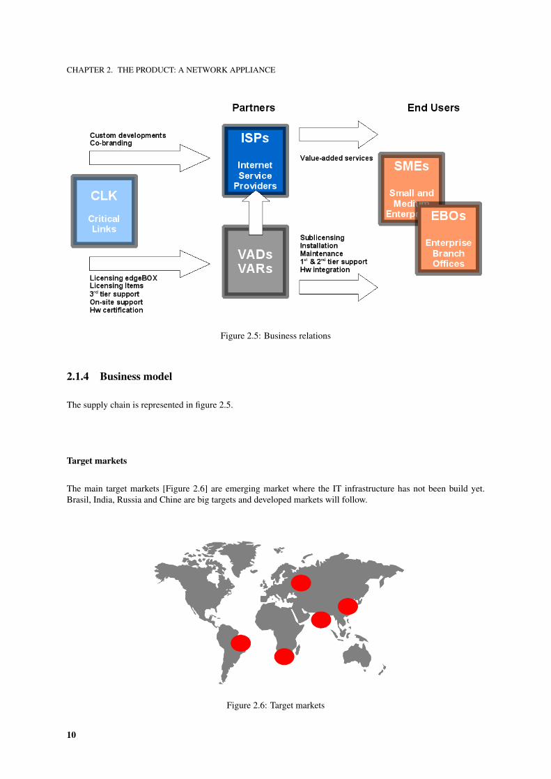
Figure 2.5: Business relations
2.1.4 Business model
The supply chain is represented in figure 2.5.
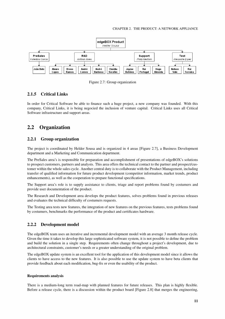
Target markets
The main target markets [Figure 2.6] are emerging market where the IT infrastructure has not been build yet.Brasil, India, Russia and Chine are big targets and developed markets will follow.
Figure 2.6: Target markets
10
CHAPTER 2. THE PRODUCT: A NETWORK APPLIANCE
Figure 2.7: Group organization
2.1.5 Critical Links
In order for Critical Software be able to finance such a huge project, a new company was founded. With thiscompany, Critical Links, it is being negocied the inclusion of venture capital. Critical Links uses all CriticalSoftware infrastructure and support areas.
2.2 Organization
2.2.1 Group organization
The project is coordinated by Helder Sousa and is organized in 4 areas [Figure 2.7], a Business Developmentdepartment and a Marketing and Communication department.
The PreSales area’s is responsible for preparation and accomplishment of presentations of edgeBOX’s solutionsto prospect customers, partners and analysts. This area offers the technical contact to the partner and prospect/cus-tomer within the whole sales cycle. Another central duty is to collaborate with the Product Management, includingtransfer of qualified information for future product development (competitor information, market trends, productenhancements), as well as the cooperation to prepare functional specifications.
The Support area’s role is to supply assistance to clients, triage and report problems found by costumers andprovide user documentation of the product.
The Research and Development area develops the product features, solves problems found in previous releasesand evaluates the technical difficulty of costumers requests.
The Testing area tests new features, the integration of new features on the previous features, tests problems foundby costumers, benchmarks the performance of the product and certificates hardware.
2.2.2 Development model
The edgeBOX team uses an iterative and incremental development model with an average 3 month release cycle.Given the time it takes to develop this large sophisticated software system, it is not possible to define the problemand build the solution in a single step. Requirements often change throughout a project’s development, due toarchitectural constraints, customer’s needs or a greater understanding of the original problem.
The edgeBOX update system is an excellent tool for the application of this development model since it allows theclients to have access to the new features. It is also possible to use the update system to have beta clients thatprovide feedback about each modification, bug-fix or even the usability of the product.
Requirements analysis
There is a medium-long term road-map with planned features for future releases. This plan is highly flexible.Before a release cycle, there is a discussion within the product board [Figure 2.8] that merges the engineering,
11
CHAPTER 2. THE PRODUCT: A NETWORK APPLIANCE
Figure 2.8: Group meetings
(a) Wiki (b) CVS (c) Salome
(d) Bugzilla (e) Sugar (f) Enterprise Architect
Figure 2.9: Coordination tools
sales, clients and management views. A special attention in given to the client’s view, represented by the PreSalesarea.
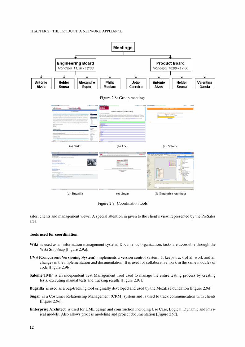
Tools used for coordination
Wiki is used as an information management system. Documents, organization, tasks are accessible through theWiki SnipSnap [Figure 2.9a].
CVS (Concurrent Versioning System) implements a version control system. It keeps track of all work and allchanges in the implementation and documentation. It is used for collaborative work in the same modules ofcode [Figure 2.9b].
Salome TMF is an independent Test Management Tool used to manage the entire testing process by creatingtests, executing manual tests and tracking results [Figure 2.9c].
Bugzilla is used as a bug-tracking tool originally developed and used by the Mozilla Foundation [Figure 2.9d].
Sugar is a Costumer Relationship Management (CRM) system and is used to track communication with clients[Figure 2.9e].
Enterprise Architect is used for UML design and construction including Use Case, Logical, Dynamic and Phys-ical models. Also allows process modeling and project documentation [Figure 2.9f].
12

CHAPTER 2. THE PRODUCT: A NETWORK APPLIANCE
Figure 2.10: Product comparison
2.3 Comparison with other products
Although the market of converged offices in a box is extremely competitive, the edgeBOX offers a very completesolution with several unique selling points.
The edgeBOX focus on service providers and is designed from scratch with end-to-end support for managedservices through Items. It has a software approach using COTS hardware enabling shorter period developmentand carrier certification cycles. It is the most comprehensive and integrated IP, IT and VoIP solution in the market.With the use of open standards and open software has a great expandability and mainly because of that, it has avery competitive price targeting SMEs.
Figure 2.10 shows a comparison with similar products comparing the price, data capabilities and voice capabilities.It is perceptible that edgeBOX offers the most comprehensive product with the best quality/price relation.
2.4 Product architecture
2.4.1 The operating system
The edgeBOX Operating System (eOS) uses the linux kernel. Some parts of the eOS are based in Debian and inLinux From Scratch (LFS).
2.4.2 Packages manager and licences authentication
Each license has a server entry with the version it is running and an hardware key. The installer, during theinstallation, checks if the license is valid comparing the local hardware key and the server key version.
13

CHAPTER 2. THE PRODUCT: A NETWORK APPLIANCE
Figure 2.11: Architecture and flow of the configuration system.
During the updates, besides checking the hardware key, the edgeBOX uses the information in the server to installthe right packages of the appropriate version.
2.4.3 Configuration architecture
When there is a configuration change [Figure 2.11] through the web interface, that change is sent to the PolicyDecision Point (PDP). After that, the PDP sends the information to the Policy Enforcement Point (PEP) whichapplies the changes by configuring the edgeBOX operating system.
The Command Line Interface (CLI), that allows command line editing of the edgeBOX, connects directly to thePEP.
2.4.4 Request handling
The PEP scripts are written in perl and are objected-oriented modules organized in packages.
The message requests are passed to the PEP already parsed as XML::DOM elements. The PEP changes theseelements a return them to the requester.
Each PEP can implement some methods. The pre method which is executed once when the PEP is executed, thereact method which is executed each time for each XML element, the stat method to check the status of a serviceand the post method that is called after react is executed for each command node.
The PEP server is a daemon that receives requests for the PEPs, executes them and replies with the result. Ituses different processes to handle with the requests. To talk with those handlers the PEP server uses Inter ProcessCommunication (IPC).
14
CHAPTER 3. THE PROJECT: AUTOMATED TESTING PLATFORM
Chapter 3
The project: automated testing platform
3.1 Important concepts on testing
In this section, important concepts to understand posterior information are defined and explained. For a moreprofound knowledge search there are several books and websites detailed in the bibliography.
Faults and failures
Software engineers distinguish software faults from software failures. In case of a failure, the software does not dowhat the user expects. A fault is a programming error that may or may not actually manifest as a failure. A faultcan also be described as an error in the correctness of the semantic of a computer program. A fault will become afailure if the exact computation conditions are met.
White-box and black-box testing
In the terminology of testing professionals (software and some hardware) the phrases ”white box”, or ”glassbox”/”clear box”, and ”black box” testing refer to whether the test case developer has access to the source codeof the software under test, and whether the testing is done through (simulated) user interfaces or through theapplication programming interfaces either exposed by (published) or internal to the target.
In white box testing the test developer has access to the source code and can write code that links into the librarieswhich are linked into the target software. This is typical of unit tests, which only test parts of a software system.They ensure that components used in the construction are functional and robust to some degree.
In black box testing the test engineer only accesses the software through the same interfaces that the customeror user would, or possibly through remotely controllable, automation interfaces that connect another computer oranother process into the target of the test. For example a test harness might push virtual keystrokes and mouse orother pointer operations into a program through any inter-process communications mechanism, with the assurancethat these events are routed through the same code paths as real keystrokes and mouse clicks.
System testing
System testing is testing conducted on a complete, integrated system to evaluate the system’s compliance with itsspecified requirements. System testing falls within the scope of Black box testing, and as such, should require noknowledge of the inner design of the code or logic. Alpha testing and Beta testing are sub-categories of Systemtesting.
15
CHAPTER 3. THE PROJECT: AUTOMATED TESTING PLATFORM
Alfa and Beta testing
In the first phase of alpha testing, developers test the software using white box techniques. Additional inspectionis then performed using black box or grey box techniques. This is usually done by a dedicated testing team. Thisis often known as the second stage of alpha testing.
Once the alpha phase is complete, development enters the beta phase. Versions of the software, known as betaversions, are released to a limited audience outside of the company. The software is released to groups of peopleso that further testing can ensure the product has few faults or bugs. Sometimes, beta-versions are made availableto the open public to increase the feedback field to a maximal number of future users.
Testing during the beta phase, informally called beta testing, is generally constrained to black box techniquesalthough a core of test engineers are likely to continue with white box testing in parallel to the beta tests. Thus theterm beta test can refer to the stage of the software - closer to release than being ”in alpha” - or it can refer to theparticular group and process being done at that stage. So a tester might be continuing to work in white box testingwhile the software is ”in beta” (a stage) but he or she would then not be part of ”the beta test” (group/activity).
Regression testing
Regression testing is any type of software testing which seeks to uncover regression bugs. Regression bugs occurwhenever software functionality that previously worked as desired stops working or no longer works in the sameway that was previously planned. Typically regression bugs occur as an unintended consequence of programchanges.
Test case
In software engineering, a test case is a set of conditions or variables (test steps) under which a tester will determineif a requirement upon an application is partially or fully satisfied. Written test cases include a description of thefunctionality to be tested taken from either the requirements or use cases, and the preparation required to ensurethat the test can be conducted. Written test cases are usually collected into Test suites.
Scenario test
A scenario test is a test based on a hypothetical story used to help a person think through a complex problem orsystem. They can be as simple as a diagram for a testing environment or they could be a description written inprose. The ideal scenario test has five key characteristics. It is (a) a story that is (b) motivating, (c) credible, (d)complex, and (e) easy to evaluate. They are usually different from test cases in that test cases are single steps andscenarios cover a number of steps. Test suites and scenarios can be used in concert for complete system tests.
Test plan
A test plan is a systematic approach to testing a system such as a machine or software. In software testing, a testplan gives detailed testing information regarding an upcoming testing effort, including scope of testing, schedule,test deliverables, release criteria, and risks and contingencies.
Test suite
The most common term for a collection of test cases is a test suite. The test suite often also contains more detailedinstructions or goals for each collection of test cases. It definitely contains a section where the tester identifies thesystem configuration used during testing. A group of test cases may also contain prerequisite states or steps, anddescriptions of the following tests.
16
CHAPTER 3. THE PROJECT: AUTOMATED TESTING PLATFORM
Figure 3.1: Conceptual domain model
Test script
A test script is a short program written in a programming language used to test part of the functionality of asoftware system.
Testing campaign
A testing campaign is the execution of a set of the test suite with the intention of testing a functionality or a set offunctionalities.
3.2 Problem domain
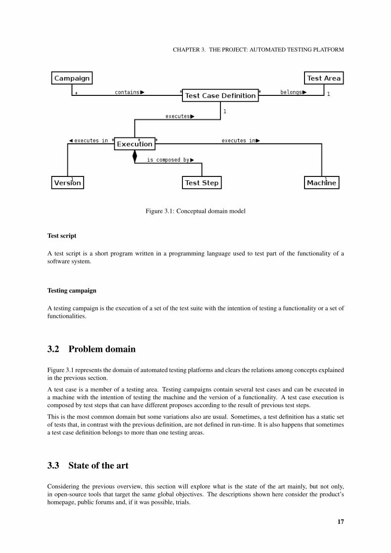
Figure 3.1 represents the domain of automated testing platforms and clears the relations among concepts explainedin the previous section.
A test case is a member of a testing area. Testing campaigns contain several test cases and can be executed ina machine with the intention of testing the machine and the version of a functionality. A test case execution iscomposed by test steps that can have different proposes according to the result of previous test steps.
This is the most common domain but some variations also are usual. Sometimes, a test definition has a static setof tests that, in contrast with the previous definition, are not defined in run-time. It is also happens that sometimesa test case definition belongs to more than one testing areas.
3.3 State of the art
Considering the previous overview, this section will explore what is the state of the art mainly, but not only,in open-source tools that target the same global objectives. The descriptions shown here consider the product’shomepage, public forums and, if it was possible, trials.
17
CHAPTER 3. THE PROJECT: AUTOMATED TESTING PLATFORM
TestDirector
TestDirector is a proprietary management tool for all aspects of software testing, ranging from capturing require-ments, storing test scripts, test execution and defect management.
Salome-TMF
Salome-TMF is an independent Test Management Tool, which manages the entire testing process - by creatingtests, executing manual or automatic tests, tracking results, managing requirements and defects and producingHTML documentation. Salome-TMF is compatible with Junit, Abbot and Beanshell to define automatic tests, andwith Bugzilla and Mantis to manage your defects. Salome-TMF can also be extended by plug-in according toyour requirements.
Bugzilla Test Runner
Bugzilla Test Runner is a test case management system that works as an add-on over the Bugzilla bug-trackingsystem.
FitNesse
FitNesse is a collaborative testing and documentation tool. It provides a very simple way for teams to collabora-tively create documents, specify tests and run those tests.
QATraq
Covers everything from defining test plans to writing test cases and recording results.
Rth
A web-based tool designed to manage requirements, tests, test results, and defects throughout the application lifecycle. The tool provides a structured approach to software testing and increases the visibility of the testing processby creating a common repository for all test assets including requirements, test cases, test plans, and test results.
Test case Web
Test Case Web is an online TCM system built with PHP and a SQL backend. It provides an efficient means forgeneration, organization, and execution reporting of test cases among projects and by multiple testers and versions.It provides various at-a-glance views of the test suite for easy status determination and test suite navigation. TCWalso provides basic reporting capabilities and per-project access control.
Tesly
Tesly is a Web application written in PHP that helps you create, execute, and report on test plans. QA leaders cantrack the progress of testing as testers use the interface to report completion of test cases.
Test Environment Toolkit
Test planning software that is a commercial package but available for free to open source, non-profit and educa-tional projects.
18
CHAPTER 3. THE PROJECT: AUTOMATED TESTING PLATFORM
Testitool
Testitool is a Web-based application for QA test planning. It creates a test plan and populates it with test cases,maps test cases to functional requirements, instantiates a test plan, begins executing test cases and marks them assuccessful or failed, generates reports on test plans, copies test plans and test cases, and tailors test plan instancesby adding and removing test cases from them.
TestLink
Web-based test management and test execution system allowing QA teams to create, manage, execute and tracktest cases and organize them into test plans.
TestMaster
A testcase management, logging, reporting and test automation tool, similar to the commercial product TestDirec-tor. Features: Progress stats, reports, test case import from CSV,doc,web or SQL, STAF plugin.
3.4 Comparison
Many of the tools mentioned above are non-commercial and have a clear lack of quality, simplicity and goodarchitecture design. The exception is Test Director. Test Director is a commercial, expensive and over-completetool. Therefore, it is not an option on the short term.
The advantages of the development of an testing platform from scratch are:
• A tool tailored to the networking product that is supposed to test.
• The merge of functional testing, load and stress testing, and benchmarks on one tool.
• An architecture suitable for network distribution.
• Ease of developing collaboration with other development tools used in the project.
More on this topic will be discussed in the results analysis [Chapter 8].
19

CHAPTER 4. REQUIREMENTS ANALYSIS
Chapter 4
Requirements analysis
Not everything that can be counted counts, and not everything that counts can be counted.– Albert Einstein
Requirements are like water. They’re easier to build on when they’re frozen.– Anonymous
The hardest part of the software task is arriving at a complete and consistent specification, and much of theessence of building a program is in fact the debugging of the specification.
– Frederick P. Brooks
4.1 Automated testing platform definition
An automated testing platform is a software tool that allows an automatic execution of previously defined auto-mated test cases1. An automated test case can be an automated functionality test, an automated load test or abenchmark.
The focus of the tool is the management and operations over test cases, testing areas and testing campaigns andthe respective results.
4.2 Objectives
In every release of developed software, new functionalities added can interfere with the core functions imple-mented previously. As mentioned, it is a resources consuming task to, in each release cycle, test all features again.Therefore, it is extremely useful to have a tool that tests, in an automated way, the core functionalities.
Having an automated testing platform, it can be used to benchmark the performance of the functionalities and totest them under high usage load.
The objectives expected to reach are:
• To develop an Automated Testing Platform (ATP) to manage and execute tests of a set of functionalities ofthe edgeBOX project.
• To make a general automated testing and benchmarking platform easily scalable and with the flexibility tobe ported to different, but with similar architecture, projects.
• To have a simple graphical interface to define which tests are going to be executed.
1. The definition of concepts used is provided in section 3.1
21
CHAPTER 4. REQUIREMENTS ANALYSIS
Figure 4.1: Actors
• To have a simple graphical interface to execute the desired actions.
• To have a simple graphical interface to see the results of the executed tests.
• To allow inspection and analysis of unexpected testing behaviour.
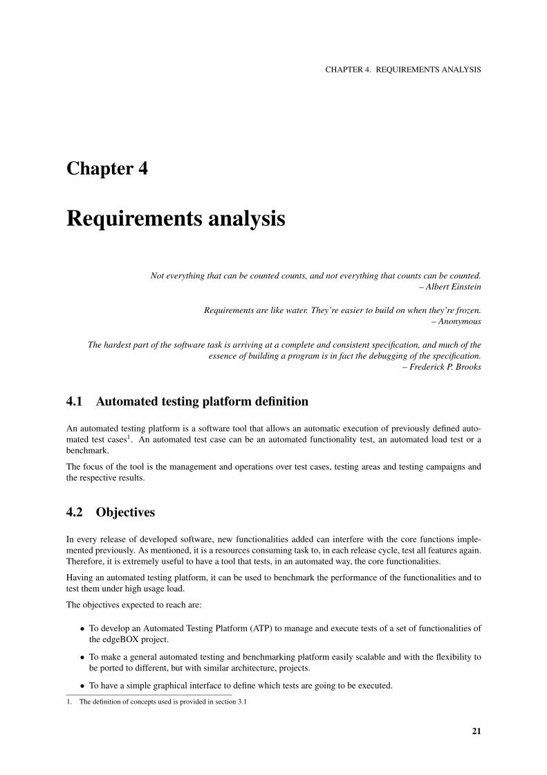
4.3 User roles and responsibilities
There are two different actors (kinds of users) of the platform [Figure 4.1].
Tester
The tester is the user that wants to test, benchmark and see the results of one or more services of the software.
Administrator
The administrator is a tester that can define, develop and document new tests in the Automated Testing Platform.
4.4 Interactions with other systems
The ATP has an interface with the application to be tested. In the case of the edgeBOX, this interface was definedto be the PDP in contrast with the CLI that connects directly with the PEP server.
This is an important point on the definition of the requirements since it enables the ATP to simulate the interactionof the Graphical User Interface (GUI) and the Items configuration module.
4.5 Functional requirements
4.5.1 Use cases
In this section the use cases of the general automated testing platform are defined.
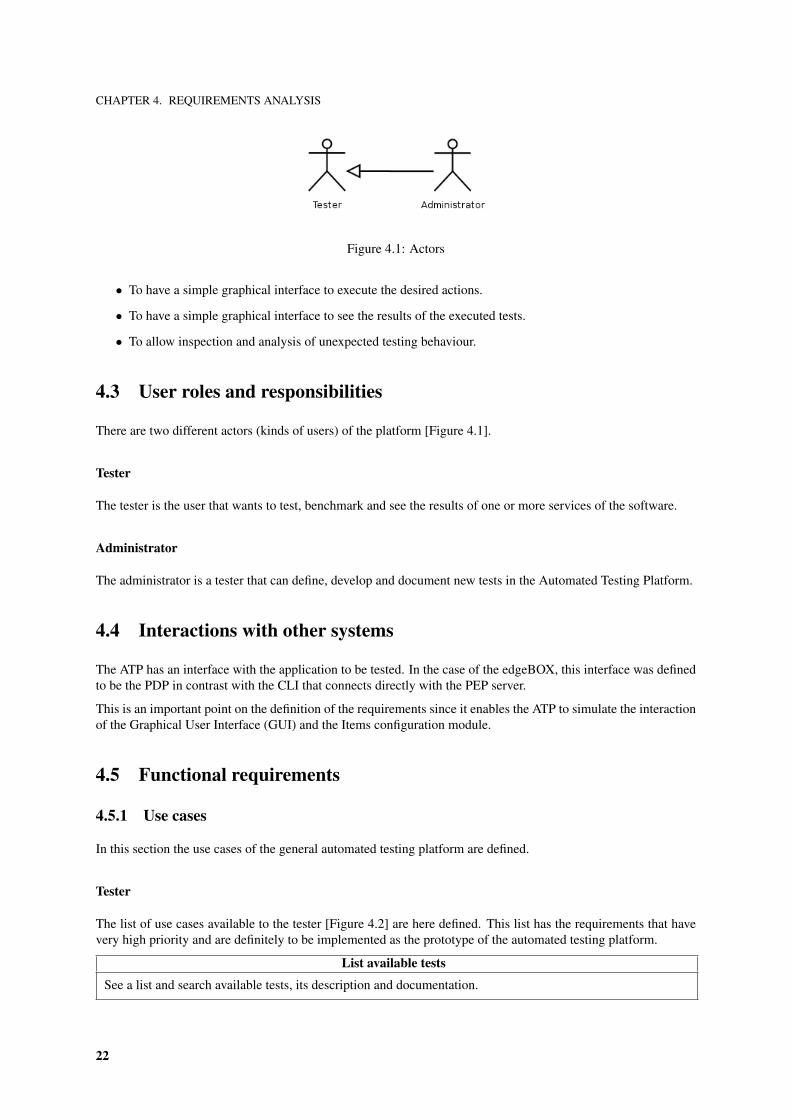
Tester
The list of use cases available to the tester [Figure 4.2] are here defined. This list has the requirements that havevery high priority and are definitely to be implemented as the prototype of the automated testing platform.
List available tests
See a list and search available tests, its description and documentation.
22
CHAPTER 4. REQUIREMENTS ANALYSIS
Figure 4.2: Tester’s use cases
List testing areas
See a list and search testing areas and its description. See the list of tests included in each testing area.
List campaigns
See a list and search testing campaigns including the lists of tests included in each campaign.
Create a new campaign
Select tests and write a description to include in a new campaign.
Execute a campaign
Execute a campaign.Execute multiple times a campaign.Execute multiple times a campaign in a concurrent manner.
23
CHAPTER 4. REQUIREMENTS ANALYSIS
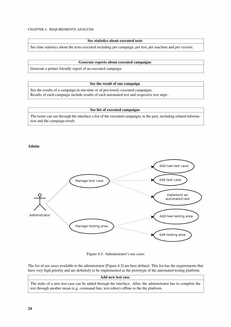
See statistics about executed tests
See time statistics about the tests executed including per campaign, per test, per machine and per version.
Generate reports about executed campaigns
Generate a printer friendly report of an executed campaign.
See the result of one campaign
See the results of a campaign in run-time or of previously executed campaigns.Results of each campaign include results of each automated test and respective test steps .
See list of executed campaigns
The tester can see through the interface a list of the executed campaigns in the past, including related informa-tion and the campaign result.
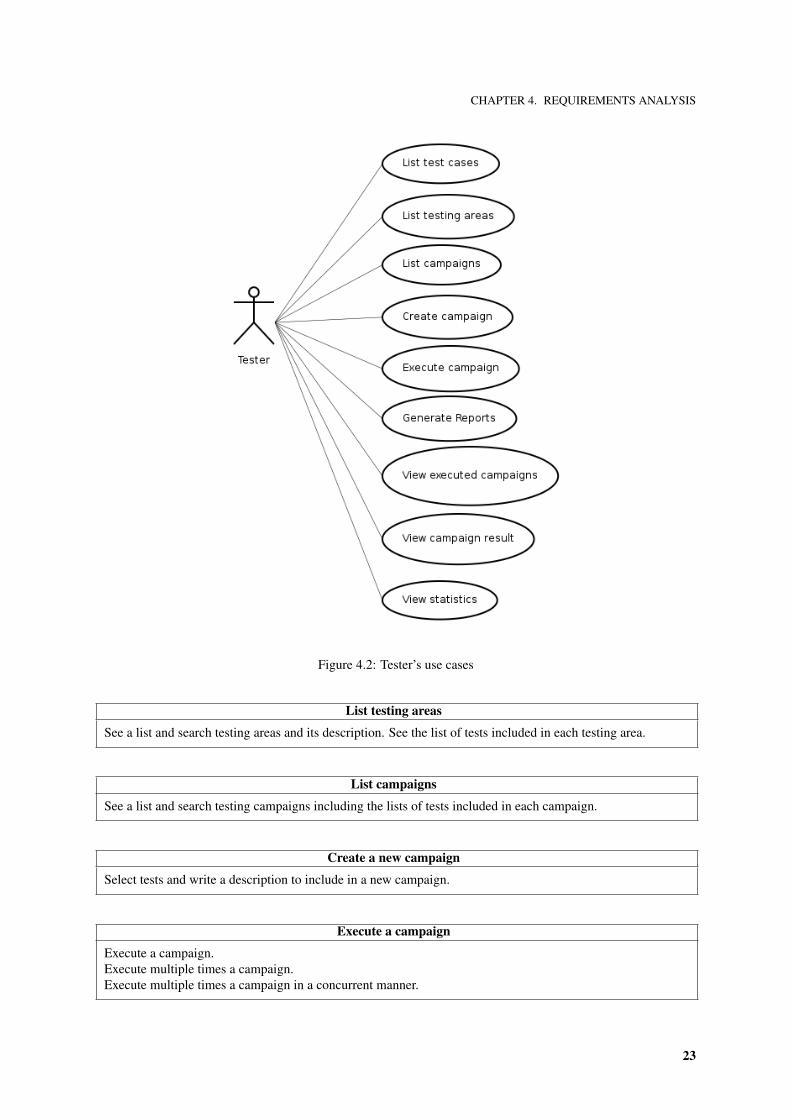
Admin
Figure 4.3: Administrator’s use cases
The list of use cases available to the administrator [Figure 4.3] are here defined. This list has the requirements thathave very high priority and are definitely to be implemented as the prototype of the automated testing platform.
Add new test case
The stubs of a new test case can be added through the interface. After, the administrator has to complete thetest through another mean (e.g. command line, text editor) offline to the the platform.
24
CHAPTER 4. REQUIREMENTS ANALYSIS
Edit test case
The name, description and properties of a test case can be edited through the interface.
Configure the settings of the platform
Configure the properties of the automated testing platform.
4.5.2 Example automated test implementations required
With the objective of demonstrating the application execution a small set of automated tests is to be developed.
Services Test Priority: 1 Difficulty: 1
Users Management Priority: 1 Difficulty: 2
Authentication Priority: 1 Difficulty: 3
QoS Priority: 2 Difficulty: 3
SMTP Priority: 2 Difficulty: 2
FireWall Priority: 2 Difficulty: 4
Backup Priority: 1 Difficulty: 4
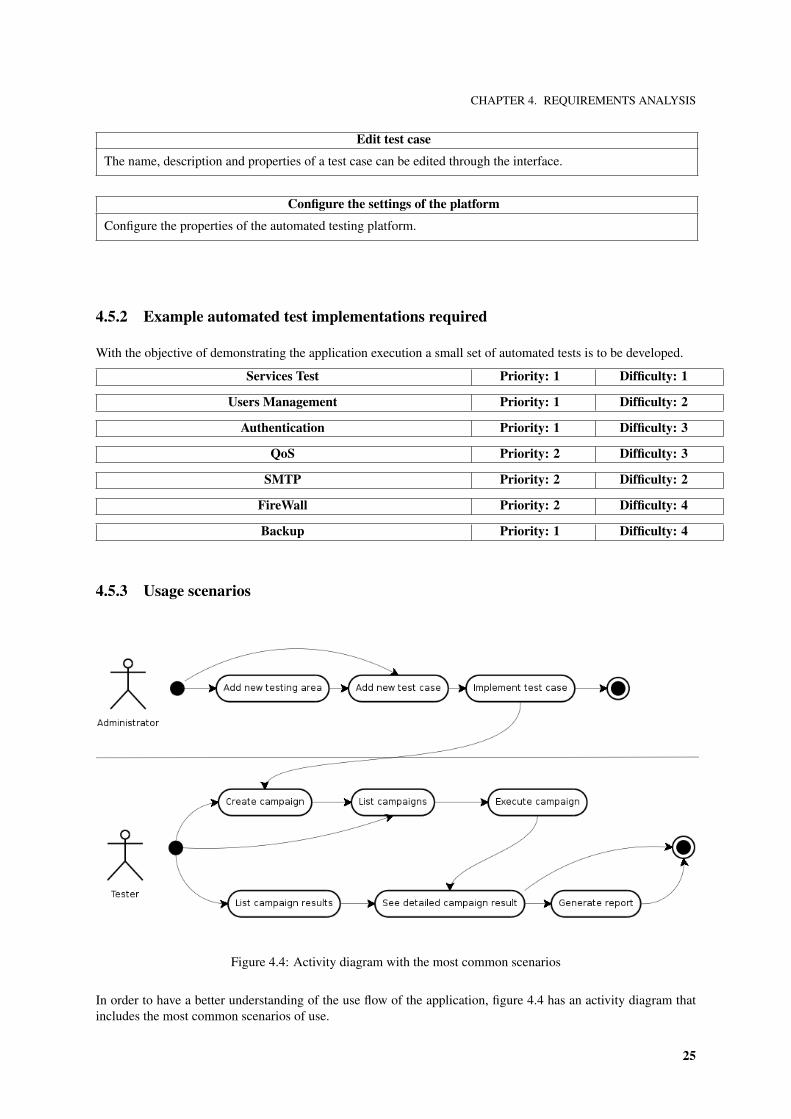
4.5.3 Usage scenarios
Figure 4.4: Activity diagram with the most common scenarios
In order to have a better understanding of the use flow of the application, figure 4.4 has an activity diagram thatincludes the most common scenarios of use.
25
CHAPTER 4. REQUIREMENTS ANALYSIS
4.6 Non-functional requirements
4.6.1 Usability
The Automated Testing Platform will follow the available standard interface guidelines on the several technologiesadopted.
It is important that the system is easy to learn. Regular software developers and testers with basic testing expe-rience shall have an easy learning process. An usability test will be performed with future users of the platform.Their comments will be taken in account.
A particularly important point is error handling.
4.6.2 Time requirements
• The time bound of the execution will be in each test time and not by internal ATP processing
• The tool will answer to user calls in an instantaneous way.
• The time measuring of executions can’t count with internal operations of the testing platform.
4.6.3 Architecture requirements
The target operating system over which the testing platform will run is Linux. But it is expected that with little orno effort porting the platform to other operating systems can be archived.
It is expected a modular architecture to assure the possibility of future improvements that may include:
• Use of the platform to manage manual test cases, areas and campaigns.
• Extension of the platform to a distributed model.
4.6.4 Hardware considerations
The platform shall be targeted for x86 architectures with recent, but not necessarily top of the art, characteristics.
4.7 User interface prototypes
Figure B.1 in appendix B includes prototypes of the user interfaces. Although rough, these prototypes are usefulto understand the style of the interface that is provided to the user.
4.8 Scope
As a first prototype, the ATP structure, and the authentication will be implemented. According to the internshipplan, this phase will be ready in the 21th of June, 2006
The automated tests are going to be implemented by priority. They are only being implemented as a proof ofconcept of the platform and are just provided as an add-on to the internship project.
26
CHAPTER 5. ARCHITECTURE AND DETAILED DESIGN
Chapter 5
Architecture and detailed design
Programming without an overall architecture or design in mind is like exploring a cave with only a flashlight:You don’t know where you’ve been, you don’t know where you’re going, and you don’t know quite where you are.
– Danny Thorpe
There are two ways of constructing a software design: One way is to make it so simple that there are obviouslyno deficiencies, and the other way is to make it so complicated that there are no obvious deficiencies.
The first method is far more difficult.– C. A. R. Hoare
5.1 Design standards
In order to have an high homogeneity level, use good software practices and maximize code reuse, Critical Soft-ware has a common set of standards used in its software development process. Among this set of standards thefollowing are of particular importance:
• The use of UML 1.4 for specification of all components of the system.
• The use of Enterprise Architect as a tool for project management and specification.
• The use of Critical Software’s coding standards.
5.2 Integration in the system
The Automated Testing Platform connects to the edgeBOX through the HTTP or HTTPS protocols using postprocedures, server and client side cookies for authentication and XML for passing parameters.
This procedure is the same that is used by the GUI and therefore enables to do the same configuration changesthat must be validated in the same way.
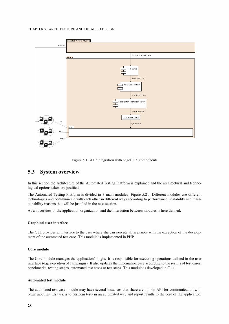
The ethernet links allow the ATP to connect to the edgeBOX as regular LAN client, WAN provider or EWAN/DMZserver. With these connections, all services provided can be tested making the ATP an useful and complete networktesting suite.
A diagram of the connection of the ATP to the edgeBOX’s components is provided in figure 5.1.
27
CHAPTER 5. ARCHITECTURE AND DETAILED DESIGN
Figure 5.1: ATP integration with edgeBOX components
5.3 System overview
In this section the architecture of the Automated Testing Platform is explained and the architectural and techno-logical options taken are justified.
The Automated Testing Platform is divided in 3 main modules [Figure 5.2]. Different modules use differenttechnologies and communicate with each other in different ways according to performance, scalability and main-tainability reasons that will be justified in the next section.
As an overview of the application organization and the interaction between modules is here defined.
Graphical user interface
The GUI provides an interface to the user where she can execute all scenarios with the exception of the develop-ment of the automated test case. This module is implemented in PHP.
Core module
The Core module manages the application’s logic. It is responsible for executing operations defined in the userinterface (e.g. execution of campaigns). It also updates the information base according to the results of test cases,benchmarks, testing stages, automated test cases or test steps. This module is developed in C++.
Automated test module
The automated test case module may have several instances that share a common API for communication withother modules. Its task is to perform tests in an automated way and report results to the core of the application.
28

CHAPTER 5. ARCHITECTURE AND DETAILED DESIGN
Figure 5.2: ATP decomposition in high-level components
This module uses the language Perl.
User interface and application’s core communication
The user interface and the core module use a mysql database to process information. All data created and actionsperformed in the user interface are added to the database. The core frequently polls the database for new requests.These requests are processed and the results are written back in the database.
Automated tests execution
The automated tests are executed by the core module using command line execution. This is important since it isintended that the languages in which the tests are executed is not specified.
Application’s core and automated tests communication
When the core executes a new automated test it opens a TCP socket connection with the test to communicateuseful information including when a test starts or finishes, what is the propose of a test step or what was the resultof a test step.
5.3.1 Architecture justification
This architecture was selected considering the several requirements defined. The requirement of scalability for adistributed system is of particular importance when the objective is to stress the target machine. In order to fulfill
29

CHAPTER 5. ARCHITECTURE AND DETAILED DESIGN
this requirement, having a central server to schedule where and when the programs are going to be executed is fun-damental. That was also the reason of the option for standard, tested and efficient TCP sockets for communicationbetween the core application and the automated test cases.
The reasons for the use of Perl to develop the test APIs was that it already exists a broad code base using thatuses Perl and that can be reused. Anyway, if there is interest in developing an API in other language, for instancePython, this should be a straight forward operation and no modifications in the other modules are required.
The language PHP was the option to use in the user interface because of the ease of use and the short developmenteffort needed.
The database choice was the open-source, complete and efficient mysql. This option is not of most importancesince all modules that have interaction with the database have data access layers that use standard and genericdatabase abstraction libraries.
5.3.2 Design Patterns
With the objective of having a very modular, scalable and maintainable platform, the following design patternswere applied.
Model-view-controller
The model-view-controller (MVC) design pattern is the model that shapes the architecture of the AutomatedTesting Platform. This software architecture separates the application’s data model, user-interface and controllogic in three distinct components causing that modifications in one component have minimal impact in others.
The model component includes the database storage mechanism and data access layers that interact with the datastorage and include domain logic to add some meaning to the raw data and object orientation. The view componentincludes the web interface and presents information to the user. The controller component includes the core of theapplication and the automated test cases.
Client-server
The controller component of the MVC design pattern implements another architectural design pattern, the client-server model. The core of the application is considered the server and executes several instances of automated testcases, waits for requests and processes them. Each test case is considered a client that connects to the server andplaces notifications of the status of the test.
Interface pattern
The interface pattern is used in communication among different modules. When two modules communicate,abstraction class or interfaces are used. This is clear in the database abstraction classes in user interface andapplication’s core modules. Another use of this pattern is in the communication class between the automated testand the core.
Bridge pattern
The bridge pattern is used in the core of the application when all runnable tests have an abstraction and use thevirtual execution and timer function which can have different implementations. This is useful since measuringtime or executing a campaign can be different of doing the same in a single test and in case of modification in oneof these methods, the modifications are encapsulated in one class.
30
CHAPTER 5. ARCHITECTURE AND DETAILED DESIGN
Figure 5.3: Class diagram of the ATP
Extensibility pattern
The automated testing platform allows users to add extensions to the platform in form of new tests. New testcan be added through the user interface without the modification or compilation of the platform’s code. This isarchived by using the client-server model and the interface pattern.
5.4 Data model
Considering the domain model represented in figure 3.1, data models were constructed and refined with the ob-jective to have appropriate data structure and model with efficient performance and expansion capabilities.
5.4.1 Class model
Figure 5.3 includes the class diagram used in the architecture of the system.
This figure is a refinement of the domain model [Figure 3.1]. The most significant change is the introduction of aclass to represent the campaign execution with the objective of simplifying the implementation of the requirementsthat include operations with campaigns.
On this diagram, the level of detail was also increased by the specification of the attributes in each class. Anin-depth view of the attributes is presented in the next section.
5.4.2 Physical model
The database model used in the ATP is in the third normal form and is represented in the figure 5.4. It was anoption taken not to go in much detail since the much of the data and relationships were already explained.
The tables defined can be classified on three different types. The class definition type, the class execution type andthe results of execution.
The class definition type represents the tables that define the concepts used in the domain. These concepts’definition includes the tables version, machine, testarea, testcasedefinition, campaign and the table campaign testthat is used to represent the n-to-n connection between a campaign and a testcasedefinition. The attributes of these
31
CHAPTER 5. ARCHITECTURE AND DETAILED DESIGN
Figure 5.4: Physical model of the ATP
32

CHAPTER 5. ARCHITECTURE AND DETAILED DESIGN
Figure 5.5: Components of the core module
tables have keys that represent the logical connection among them and descriptive attributes like the name of theentity and, sometimes, the description of the class.
The class execution type is used to represent information about the execution of the class definition. Tablescampaignexecution, testexecution and teststep have information about the objective of the execution, the target ofthe execution, the way that the execution in going to be performed (e.g. parallel or sequential) and time informationabout the start of the execution.
The results of execution type is used to store the information about the results of an execution. The tables cam-paignresult, testexecutionresult and teststepresult include information about to which execution they belong, aninteger result of the execution using the posix returning results convention, a textual description of the result inorder to include some automatic error information retrieval and information about the end time of the execution.
5.5 System decomposition
This section explores the several modules of the platform in detail.
5.5.1 Core module
The core of the ATP [Figure 5.5] follows an object oriented architecture implemented in C++ that uses the modeldescribed in figure 5.3. The architectures uses, in an interesting way, the bridge design pattern. There are classesthat implement the timing and execution functions, this brings an excellent modularity to the system making itpossible to change the way the timer and the executor works without changing the implementation of the objects.
The core module has a set of components that have crucial importance:
Timer This class has abstractions to OS timer functions and declares virtual functions to that are implemented inthe internal data structures.
33
CHAPTER 5. ARCHITECTURE AND DETAILED DESIGN
Figure 5.6: Components of the user interface
Runner This class has abstractions to the OS execution functions and declares virtual functions that are imple-mented in the internal data structures.
Data access ObjectFactory When the database is pooled, this class generates the object to the internal structuresaccording to the elements created by the user in the user interface.
Data access ObjectRecorder When important changes occur in the internal data objects, the ObjectRecordersaves the information back in the database so it can be accessible to the user.
Test communication ObjectFactory Once that the creation of test steps is dynamic and can happen in runtime,when the test reports a new test step, the communication layer constructs the object automatically andappends it to the internal data structures.
Testing script communication
As explained before, the communication with the testing script uses sockets abstracted in a multi-operating systemlibrary. The messages passed using XML as defined in the following document type definition (DTD).
<!DOCTYPE test [<!ELEMENT test (test?,(logfile?,description?,status))><!ATTLIST test name CDATA #REQUIRED><!ELEMENT description (#PCDATA)><!ELEMENT logfile (#PCDATA)><!ELEMENT status (PASS|FAIL)>
]>
5.5.2 User interface
The web interface chosen platform is PHP4 producing a web accessible HTTP interface. This interface is veryflexible because the HTTP protocol is a wide spread standard and can be accessed from a remote computer.
The user interface has two main layers. The data access layer produces an abstraction to the database communi-cation. The web interface layer shows information and allows users to pass actions to the core application.
The data access layer has the following main components.
Add Operations In this component, the operations that add records to the database are defined and implemented.
Update Operations In this component, the operations that update records in the database are defined and imple-mented.
34
CHAPTER 5. ARCHITECTURE AND DETAILED DESIGN
Delete Operations In this component, the operations that remove records from the database are defined andimplemented.
Select Operations In this component, the operations that select records from the database are defined and imple-mented.
The web interface has the following main components.
Test Manager This component shows information and provides operations over tests.
Area Manager This component shows information and provides operations over areas.
Campaign Manager This component shows information and provides operations over campaigns.
AJAX Campaign Run-Time Presenter This component uses Asynchronous JavaScript and XML (AJAX) withthe objective of providing an interactive real-time presentation of the global state and test details of a cam-paign execution.
Statistics calculator This component calculates the statistics defined in the requirements and shows them in auser friendly way.
In the architecture of the user interface some usability design patterns are to be followed.
Search do not sort! This Gmail like usability design pattern was followed by keeping sorting to a minimum,allowing the user to search all tests, campaigns and test steps.
Content/Operations separtion There is a clear separation of content and operation by the use of menus.
The users’ manual and a demonstration of the application is included in section 7.2.
5.5.3 Automated test case
A components diagram of this module is available in figure 5.7.
An automated test case uses three APIs that were implemented using Perl Modules but that, because of the mod-ularity of the system, can be easily implemented in other computer languages. The use of these APIs bringsgreat abstraction to the code, promotes code reutilization and don’t cause the system to be recompiled since aninterpreted language is used.
The ATP protocol’s layer implements an interface to the protocol so that the user can abstract it and use simplefunctions instead. Functions to initialize the protocol, start a test step or declare the result of a test step areprovided.
The configuration API abstract the protocol of configuration causing that if the functionality changes, the changein the automated test only has to be correct one time.
The system API is offered by the language itself and doesn’t ties the code to any operating system or architecture,as long there is an interpreter of Perl to that operating system or computer architecture.
The use of these APIs cause that the code of an automated test to be almost similar to pseudo-code. To illustrate,a very simple example of this code is in figure 5.8.
35
CHAPTER 5. ARCHITECTURE AND DETAILED DESIGN
Figure 5.7: Components of an automated test case
# ! / u s r / b i n / p e r luse ATP ;
$ a t p = ATP−>new ($ARGV [ 0 ] ) ; # s t a r t t h e communica t ion w i t h t h e s e r v e ri f ( ! $a tp−>l o g i n ( ) ) { # l o g i n as an a d m i n i s t r a t o r
e x i t 1 ; # f a i l e d t o l o g i n ( t h i s e r r o r i s r e p o r t e d a u t o m a g i c a l y )}my $ i d = $a tp−>s t a r t S t e p ( ” Turn on NAT” ) ; # d e c l a r e a new t e s t w i t h a purpose$a tp−>se tNatOn ( ) ; # use t h e c o n f i g u r a t i o n API t o t u r n t h e ne twork t r a n s a t i o n oni f ( $a tp−>n a t I s O n ( ) ) { # v e r i f y c u r r e n t s t a t u s
$a tp−>endS tep ( $id , 0 , ” Succeeded t o t u r n NAT on ” ) ; # r e p o r t s u c c e s s$a tp−>end ( ) ;e x i t 0 ;
}$a tp−>endS tep ( $id , 1 , ” F a i l e d t o t u r n NAT on ” ) ; # r e p o r t f a l u r e$a tp−>end ( ) ;e x i t 1 ;
Figure 5.8: Example of an automated test
36

CHAPTER 6. TESTING AND SOFTWARE QUALITY ASSURANCE
Chapter 6
Testing and software quality assurance
An effective way to test code is to exercise it at its natural boundaries.– Brian Kernighan
Program testing can be used to show the presence of bugs, but never to show their absence!– Edsger Dijkstra
Beware of bugs in the above code; I have only proved it correct, not tried it.– Donald Knuth
6.1 Scope of testing
This chapter gives an overview of the software quality assurance used in all the development process, the testspecification and the test execution.
The software quality assurance used, follows the Critical’s Quality Management System (QMS) and has the ob-jective of producing high quality standards software. Most of the process described here uses the tool EnterpriseArchitect that simplifies the organization of testing plans and software quality assurance.
6.2 Schedule
The testing process was distributed along the development of the software. Although this temporal distribution,there were three periods where there was a bigger focus on testing. From 21st to 29th of June, the testing wastargeted to the functionalities offered by the prototype. From the 18th of July to the 1st of August, the platformwas tested in the release 4.1 of the edgeBOX by beta usage of the implemented automated tests (e.g. test of thebackup and restore feature). In the first fifteen days of August a more methodical approach to tests was takenincluding the documentation of unit tests performed during the development, specified functional tests and codeinspection.
6.3 Approach
The test of features is going to be based almost completely on tests of the use cases. Another crucial point is inthe proof of user introduced errors on the use of library of communication with the application’s core with thetest scripts. This last test has particular importance since it could cause testing data to be badly organized or theapplication to run unpredictably.
37

CHAPTER 6. TESTING AND SOFTWARE QUALITY ASSURANCE
Other quality assurances, not only focused in features, include code inspections and module unit testing of thecore of the application by feeding simulated user operations and executing simulated test cases.
6.4 Test cases
This section lists a summary of the set of test cases defined for the application including the purpose, expectedresult and obtained result but omitting the test steps in order to provide useful, readable and understandableinformation.
Testing areas
Testing summary:
1. Create a new testing area with valid name and description.
2. Create a new testing area with the same name to one that already exists.
3. Create a new testing area with names bigger than the allowed.
4. Try the three previous tests in edition of an already existing area.
5. Try several searches of existing testing areas.
Expected results:
1. The area must be listed in the list of testing areas.
2. An error must be presented to the user.
3. It can’t be possible to introduce more than the number of allowed characters in the text fields.
4. The same results of the previous tests must occur.
5. The list of the testing areas must be narrowed to match the search.
Results archived:The expected results were obtained.
Test cases
Testing summary:
1. Check listed testing areas in the option menu when adding a new test
2. Create a new test case with valid name, description and testing area.
3. Create a new test case with the same name to one that already exists.
4. Create a new test case with names bigger than the allowed.
5. Try the previous tests in edition of an already existing test.
6. Try several searches of existing test cases.
7. Follow the create stub link.
Expected results:
1. All existing areas must be listed in the option menu.
2. The test must be listed in the list of test cases.
3. An error must be presented to the user.
4. It can’t be possible to introduce more than the number of allowed characters in the text fields.
5. The same results of the previous tests must occur.
6. The list of the test cases must be narrowed to match the search.
7. A sample automated test must be created in the file system and the create stub link must disappear.
Results archived:The expected results were obtained.
38
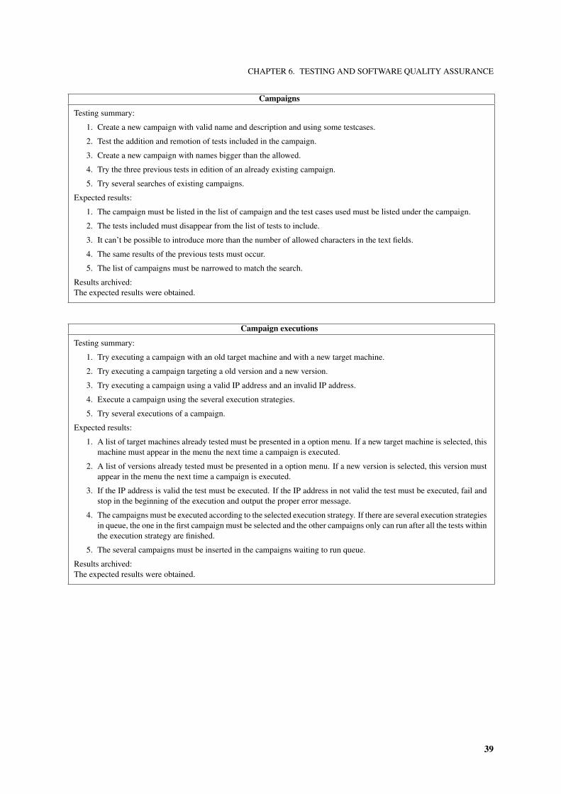
CHAPTER 6. TESTING AND SOFTWARE QUALITY ASSURANCE
Campaigns
Testing summary:
1. Create a new campaign with valid name and description and using some testcases.
2. Test the addition and remotion of tests included in the campaign.
3. Create a new campaign with names bigger than the allowed.
4. Try the three previous tests in edition of an already existing campaign.
5. Try several searches of existing campaigns.
Expected results:
1. The campaign must be listed in the list of campaign and the test cases used must be listed under the campaign.
2. The tests included must disappear from the list of tests to include.
3. It can’t be possible to introduce more than the number of allowed characters in the text fields.
4. The same results of the previous tests must occur.
5. The list of campaigns must be narrowed to match the search.
Results archived:The expected results were obtained.
Campaign executions
Testing summary:
1. Try executing a campaign with an old target machine and with a new target machine.
2. Try executing a campaign targeting a old version and a new version.
3. Try executing a campaign using a valid IP address and an invalid IP address.
4. Execute a campaign using the several execution strategies.
5. Try several executions of a campaign.
Expected results:
1. A list of target machines already tested must be presented in a option menu. If a new target machine is selected, thismachine must appear in the menu the next time a campaign is executed.
2. A list of versions already tested must be presented in a option menu. If a new version is selected, this version mustappear in the menu the next time a campaign is executed.
3. If the IP address is valid the test must be executed. If the IP address in not valid the test must be executed, fail andstop in the beginning of the execution and output the proper error message.
4. The campaigns must be executed according to the selected execution strategy. If there are several execution strategiesin queue, the one in the first campaign must be selected and the other campaigns only can run after all the tests withinthe execution strategy are finished.
5. The several campaigns must be inserted in the campaigns waiting to run queue.
Results archived:The expected results were obtained.
39
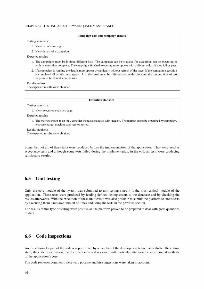
CHAPTER 6. TESTING AND SOFTWARE QUALITY ASSURANCE
Campaign lists and campaign details
Testing summary:
1. View list of campaigns
2. View details of a campaign.
Expected results:
1. The campaigns must be in three different lists. The campaign can be in queue for execution, can be executing orwith its execution complete. The campaigns finished executing must appear with different colors if they fail or pass.
2. If a campaign is running the details must appear dynamically without refresh of the page. If the campaign executionis completed all details must appear. Also the result must be differentiated with colors and the running time of teststeps must be available to the user.
Results archived:The expected results were obtained.
Execution statistics
Testing summary:
1. View execution statistics page.
Expected results:
1. The metrics shown must only consider the tests executed with success. The metrics are to be organized by campaign,test case, target machine and version tested.
Results archived:The expected results were obtained.
Some, but not all, of these tests were produced before the implementation of the application. They were used asacceptance tests and although some tests failed during the implementation, in the end, all tests were producingsatisfactory results.
6.5 Unit testing
Only the core module of the system was submitted to unit testing since it is the most critical module of theapplication. These tests were produced by feeding defined testing orders to the database and by checking theresults afterwards. With the execution of these unit tests it was also possible to submit the platform to stress testsby executing them a massive amount of times and doing the tests in the previous section.
The results of this type of testing were positive an the platform proved to be prepared to deal with great quantitiesof data.
6.6 Code inspections
An inspection of a part of the code was performed by a member of the development team that evaluated the codingstyle, the code organization, the documentation and reviewed with particular attention the most crucial methodsof the application’s core.
The code reviewer comments were very positive and his suggestions were taken in account.
40
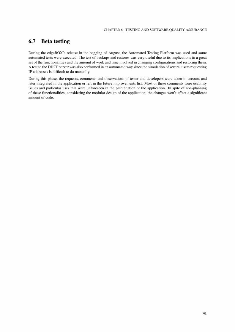
CHAPTER 6. TESTING AND SOFTWARE QUALITY ASSURANCE
6.7 Beta testing
During the edgeBOX’s release in the begging of August, the Automated Testing Platform was used and someautomated tests were executed. The test of backups and restores was very useful due to its implications in a greatset of the functionalities and the amount of work and time involved in changing configurations and restoring them.A test to the DHCP server was also performed in an automated way since the simulation of several users requestingIP addresses is difficult to do manually.
During this phase, the requests, comments and observations of tester and developers were taken in account andlater integrated in the application or left in the future improvements list. Most of these comments were usabilityissues and particular uses that were unforeseen in the planification of the application. In spite of non-planningof these functionalities, considering the modular design of the application, the changes won’t affect a significantamount of code.
41

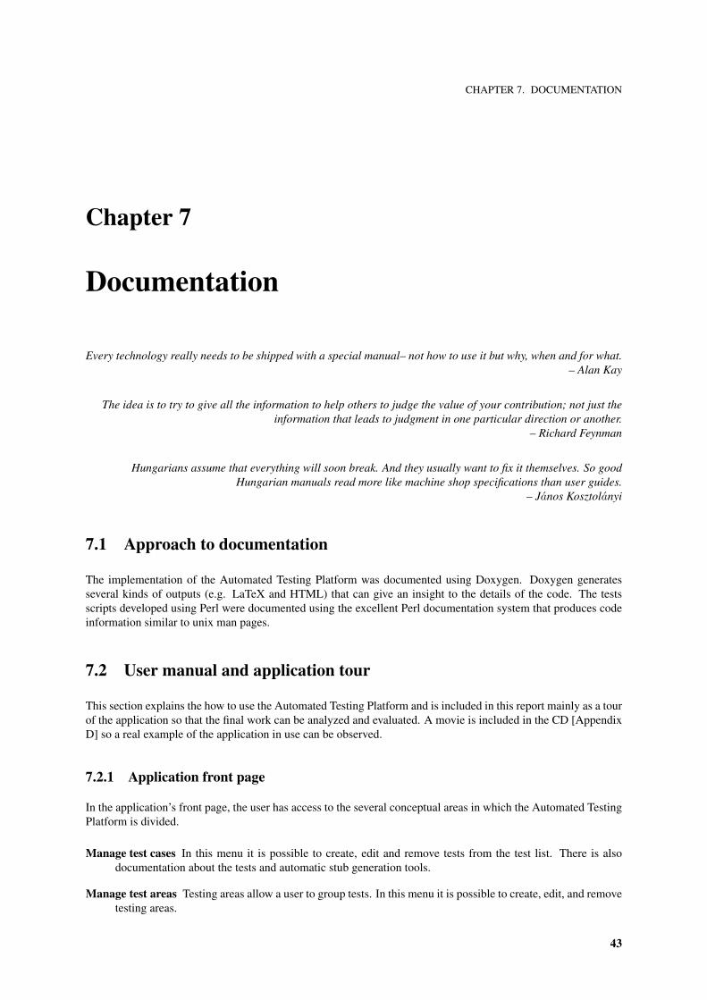
CHAPTER 7. DOCUMENTATION
Chapter 7
Documentation
Every technology really needs to be shipped with a special manual– not how to use it but why, when and for what.– Alan Kay
The idea is to try to give all the information to help others to judge the value of your contribution; not just theinformation that leads to judgment in one particular direction or another.
– Richard Feynman
Hungarians assume that everything will soon break. And they usually want to fix it themselves. So goodHungarian manuals read more like machine shop specifications than user guides.
– Janos Kosztolanyi
7.1 Approach to documentation
The implementation of the Automated Testing Platform was documented using Doxygen. Doxygen generatesseveral kinds of outputs (e.g. LaTeX and HTML) that can give an insight to the details of the code. The testsscripts developed using Perl were documented using the excellent Perl documentation system that produces codeinformation similar to unix man pages.
7.2 User manual and application tour
This section explains the how to use the Automated Testing Platform and is included in this report mainly as a tourof the application so that the final work can be analyzed and evaluated. A movie is included in the CD [AppendixD] so a real example of the application in use can be observed.
7.2.1 Application front page
In the application’s front page, the user has access to the several conceptual areas in which the Automated TestingPlatform is divided.
Manage test cases In this menu it is possible to create, edit and remove tests from the test list. There is alsodocumentation about the tests and automatic stub generation tools.
Manage test areas Testing areas allow a user to group tests. In this menu it is possible to create, edit, and removetesting areas.
43

CHAPTER 7. DOCUMENTATION
Figure 7.1: Main page - interface
Manage campaigns A test campaign is a set of tests to be executed. In this menu it is possible to view, create,edit, remove and execute a campaign.
List executions In this menu it is possible to view a summary and the details of running, past and pendingexecutions.
Show statistics In this menu it is possible to view execution time statistics of campaigns, tests and versions.
An image of the application’s front page is available in figure 7.1.
7.2.2 Manage tests
When opening the Manage test menu, the user is presented with the list of tests in the system [Figure 7.2a]. Then,using the search box on the right, it’s possible to filter the list by keywords [Figure 7.2b].
To create a new automated test case, click on the link on the right side. A new form will appear where the testname, a descriptive text are inserted and the area, in which the test in included, is selected from the list of existingareas [Figure 7.2c]. By submitting the form, the page is reloaded, a confirmation that the test was included in theapplication is presented and the test is listed in the list of tests.
A test can be deleted or edited by selecting the proper operation in operation column in the list of test. To edit, asimilar form as to add a new test is presented with the current test definitions.
After adding a new test it is possible to create the skeleton of the test script by pressing the Create stub link [Figure7.2d]. This stub is created in the tests directory in the base folder of the application. Then, the user have to editthe test by programming in the language Perl. Other languages can be used just by declaring the language in thebegging of the script in the standard unix shell way.
7.2.3 Manage areas
The list of testing areas is available in the Manage areas menu [Figure 7.3b]. By using the search box in the rightthe used can narrow the list.
To add a new area, click on the link on the right side. A form where the user can enter the name and descriptionof the area appears and, after submitting the form, the new area is listed alongside the other areas.
The possibility of removing or editing an area is available in the operation column in the list of areas. The schemefor editing is the same than for addition of a new area.
44
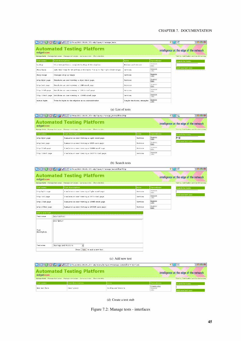
CHAPTER 7. DOCUMENTATION
(a) List of tests
(b) Search tests
(c) Add new test
(d) Create a test stub
Figure 7.2: Manage tests - interfaces
45
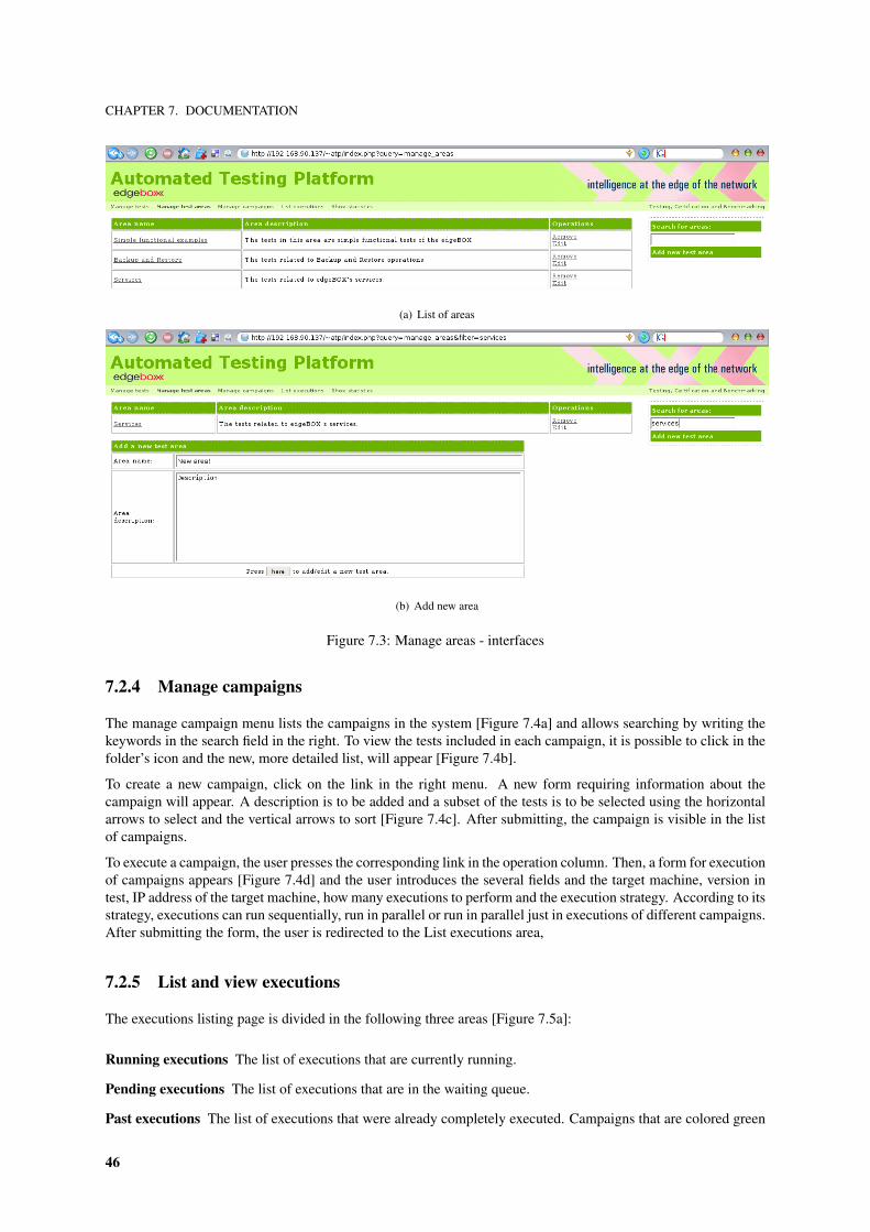
CHAPTER 7. DOCUMENTATION
(a) List of areas
(b) Add new area
Figure 7.3: Manage areas - interfaces
7.2.4 Manage campaigns
The manage campaign menu lists the campaigns in the system [Figure 7.4a] and allows searching by writing thekeywords in the search field in the right. To view the tests included in each campaign, it is possible to click in thefolder’s icon and the new, more detailed list, will appear [Figure 7.4b].
To create a new campaign, click on the link in the right menu. A new form requiring information about thecampaign will appear. A description is to be added and a subset of the tests is to be selected using the horizontalarrows to select and the vertical arrows to sort [Figure 7.4c]. After submitting, the campaign is visible in the listof campaigns.
To execute a campaign, the user presses the corresponding link in the operation column. Then, a form for executionof campaigns appears [Figure 7.4d] and the user introduces the several fields and the target machine, version intest, IP address of the target machine, how many executions to perform and the execution strategy. According to itsstrategy, executions can run sequentially, run in parallel or run in parallel just in executions of different campaigns.After submitting the form, the user is redirected to the List executions area,
7.2.5 List and view executions
The executions listing page is divided in the following three areas [Figure 7.5a]:
Running executions The list of executions that are currently running.
Pending executions The list of executions that are in the waiting queue.
Past executions The list of executions that were already completely executed. Campaigns that are colored green
46
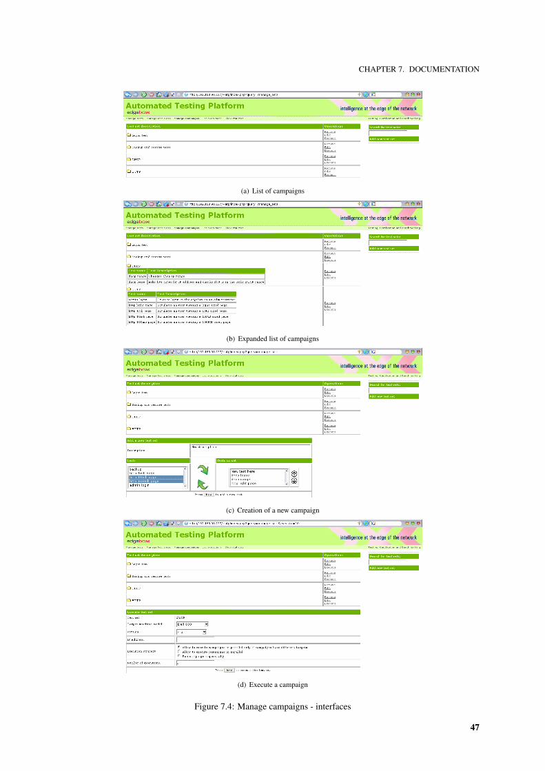
CHAPTER 7. DOCUMENTATION
(a) List of campaigns
(b) Expanded list of campaigns
(c) Creation of a new campaign
(d) Execute a campaign
Figure 7.4: Manage campaigns - interfaces
47
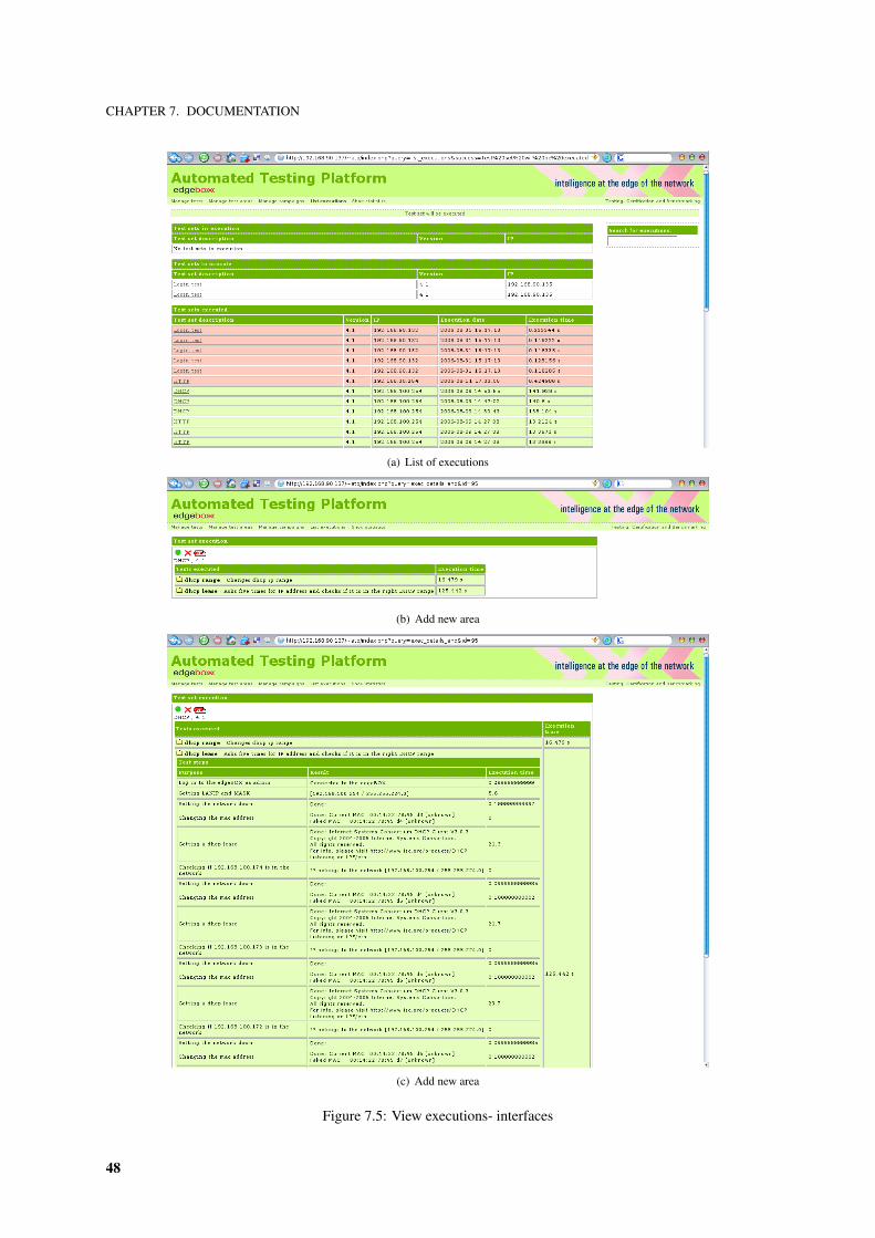
CHAPTER 7. DOCUMENTATION
(a) List of executions
(b) Add new area
(c) Add new area
Figure 7.5: View executions- interfaces
48
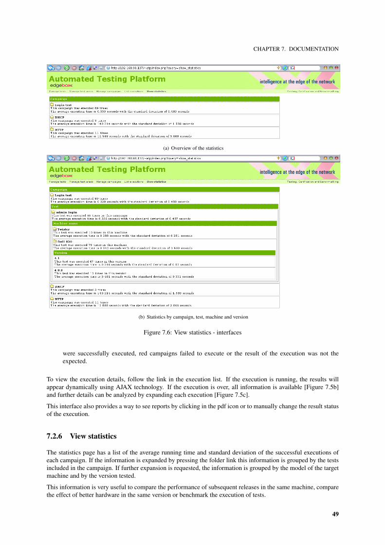
CHAPTER 7. DOCUMENTATION
(a) Overview of the statistics
(b) Statistics by campaign, test, machine and version
Figure 7.6: View statistics - interfaces
were successfully executed, red campaigns failed to execute or the result of the execution was not theexpected.
To view the execution details, follow the link in the execution list. If the execution is running, the results willappear dynamically using AJAX technology. If the execution is over, all information is available [Figure 7.5b]and further details can be analyzed by expanding each execution [Figure 7.5c].
This interface also provides a way to see reports by clicking in the pdf icon or to manually change the result statusof the execution.
7.2.6 View statistics
The statistics page has a list of the average running time and standard deviation of the successful executions ofeach campaign. If the information is expanded by pressing the folder link this information is grouped by the testsincluded in the campaign. If further expansion is requested, the information is grouped by the model of the targetmachine and by the version tested.
This information is very useful to compare the performance of subsequent releases in the same machine, comparethe effect of better hardware in the same version or benchmark the execution of tests.
49
CHAPTER 7. DOCUMENTATION
7.3 Installation manual
Since, almost completely, Debian based Linux distributions are used in the project, this installation manual as-sumes the apt installation suite is used. For non-debian systems, the used packages can be installed using thedistribution’s package manager.
For installing the platform execute the following commands:
# i n s t a l l d e p e n d e n c i e s$> sudo ap t−g e t i n s t a l l apache2 php5 l i b a p a c h e 2−mod−php5 g++ p e r l a u t o t o o l s
# download t h e a p p l i c a t i o n from CVS$> cvs co user@cvs . c r i t i c a l . p t : cvs / c r i t i c a l / edge−d e v i c e / i m p l e m e n t a t i o n / au tomated− t e s t i n g
# c r e a t e a s y m b o l i c l i n k i n t h e HTTP d i r e c t o r y t o t h e u s e r i n t e r f a c e$> l n −s p u b l i c h t m l / / au tomated− t e s t i n g / a t p / u i /
# c o m p i l e t h e core o f t h e a p p l i c a t i o n$> . / c o n f i g u r e$> make$> sudo make i n s t a l l
# i n s t a l l t h e p e r l module o f t h e t e s t i n g API$> . / i n s t a l l −sh
Some automated testing scripts implemented use perl libraries that have to be installed. Each of these tests includecomments with the libraries used and the user shall install them by the perl command line.
50
CHAPTER 8. FINAL CONSIDERATIONS AND RESULTS ANALYSIS
Chapter 8
Final considerations and results analysis
The single most important thing to remember about any enterprise is that there are no results inside its walls.The result of a business is a satisfied customer.
- Peter Drucker
The truth is, there are only two things in life, reasons and results, and reasons simply don’t count.– Robert Anthony
8.1 Automated testing platform results
The objectives proposed in the beginning of the internship were archived. An automated testing platform, withsome innovative functionalities, was developed as required. Some automated tests were also implemented to showthe use, functionalities and value of the platform. The results were very satisfying.
As an analysis of the platform, the unique points in comparison with the other products mentioned in section 3.3are:
• Architected to test network applications in particular the edgeBOX.
• Unifies functional testing and benckmarking.
• Architecture supports distributed automated testing.
8.1.1 Improvements
During the development and testing, some ideas for new features were suggested by the future users of the appli-cation. These include:
• Better integration among test definition on the platform and test documentation.
• An interface to provide arguments to the automated tests.
• Easier distributed system testing platform functionalities.
8.2 Automated tests results
The automated test cases implemented were just a proof of concept to show that [part of] the testing of theedgeBOX can be done using the automated testing platform. This objective was archived during the edgeBOX’s
51
CHAPTER 8. FINAL CONSIDERATIONS AND RESULTS ANALYSIS
release in the beginning of August by using the platform for testing of sensitive and difficult functionalities as thebackup or the DHCP server package.
8.3 Internship considerations
During this internship, an inside knowledge of the edgeBOX was gained. It’s was a valuable experience for me asa student to work in a real world team’s project with its time, money and quality constrains.
At a technical level, new technologies were learned, my networking knowledge has increase since it was somethingin which I didn’t had great interest during my degree and that was a gap in my formation as a computer engineer.
I learned a great deal about organization of software projects, how to contribute, as a member of a team, to a bigproject (10 members in the engineering team and 10 members in supporting areas) when there are multiple goalsand short amount of time and resources.
I’ve also gained life experience that, for sure, is going to be helpful in the rest of my professional life by moving toa different city, meeting different people from different nationalities and by working in one of the most dynamicand innovative Portuguese companies.
I feel that I’ve archived my objectives and that it was a very good choice to be an intern at Critical Software. Inmy opinion and from the feedback I’ve received, Critical’s managers were also very happy with my performance.I was evaluated according to the standards of the company having a final classification of superior (4,2 out of5), a excellent classification considering the exigence of the evaluation. I was invited to keep working at CriticalSoftware, a propose that I’m going to ponder and decide after the deliver and presentation of this report.
52
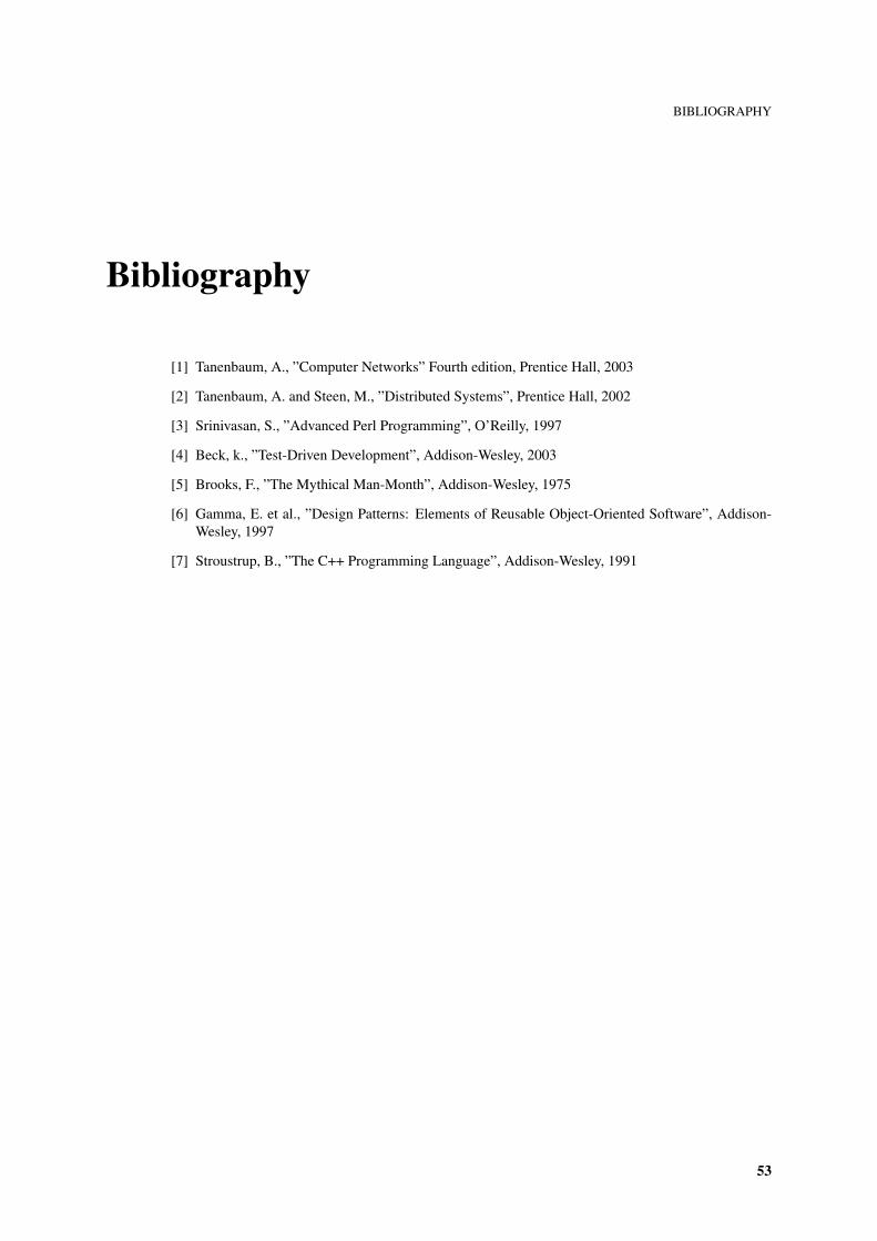
BIBLIOGRAPHY
Bibliography
[1] Tanenbaum, A., ”Computer Networks” Fourth edition, Prentice Hall, 2003
[2] Tanenbaum, A. and Steen, M., ”Distributed Systems”, Prentice Hall, 2002
[3] Srinivasan, S., ”Advanced Perl Programming”, O’Reilly, 1997
[4] Beck, k., ”Test-Driven Development”, Addison-Wesley, 2003
[5] Brooks, F., ”The Mythical Man-Month”, Addison-Wesley, 1975
[6] Gamma, E. et al., ”Design Patterns: Elements of Reusable Object-Oriented Software”, Addison-Wesley, 1997
[7] Stroustrup, B., ”The C++ Programming Language”, Addison-Wesley, 1991
53


APPENDIX A. GANT CHART
Appendix A
Gant chart
55
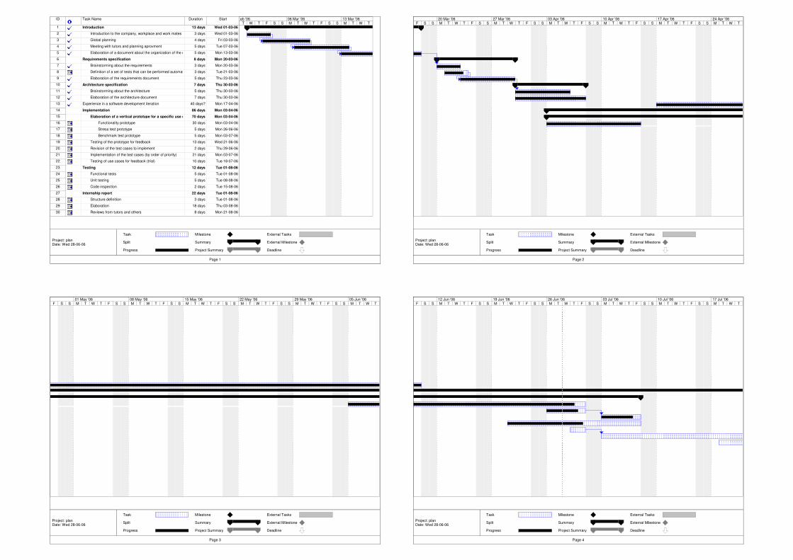
ID Task Name Duration Start
1 Introduction 13 days Wed 01-03-06
2 Introduction to the company, workplace and work mates 3 days Wed 01-03-06
3 Global planning 4 days Fri 03-03-06
4 Meeting with tutors and planning aprovment 5 days Tue 07-03-06
5 Elaboration of a document about the organization of the edgebox development, architecture and technologies involved5 days Mon 13-03-06
6 Requirements specification 8 days Mon 20-03-06
7 Brainstorming about the requirements 3 days Mon 20-03-06
8 Definition of a set of tests that can be performed automatically with the priority defined3 days Tue 21-03-06
9 Elaboration of the requirements document 5 days Thu 23-03-06
10 Architecture specification 7 days Thu 30-03-06
11 Brainstorming about the architecture 5 days Thu 30-03-06
12 Elaboration of the architecture document 7 days Thu 30-03-06
13 Experience in a software development iteration 40 days? Mon 17-04-06
14 Implementation 86 days Mon 03-04-06
15 Elaboration of a vertical prototype for a specific use case 70 days Mon 03-04-06
16 Functionality prototype 30 days Mon 03-04-06
17 Stress test prototype 5 days Mon 26-06-06
18 Benchmark test prototype 5 days Mon 03-07-06
19 Testing of the prototype for feedback 13 days Wed 21-06-06
20 Revision of the test cases to implement 2 days Thu 29-06-06
21 Implementation of the test cases (by order of priority) 21 days Mon 03-07-06
22 Testing of use cases for feedback (trial) 10 days Tue 18-07-06
23 Testing 12 days Tue 01-08-06
24 Functional tests 5 days Tue 01-08-06
25 Unit testing 5 days Tue 08-08-06
26 Code inspection 2 days Tue 15-08-06
27 Internship report 22 days Tue 01-08-06
28 Structure definition 3 days Tue 01-08-06
29 Elaboration 18 days Thu 03-08-06
30 Reviews from tutors and others 8 days Mon 21-08-06
T W T F S S M T W T F S S M T W Teb '06 06 Mar '06 13 Mar '06
Task
Split
Progress
Milestone
Summary
Project Summary
External Tasks
External Milestone
Deadline
Page 1
Project: planDate: Wed 28-06-06
F S S M T W T F S S M T W T F S S M T W T F S S M T W T F S S M T W T F S S M T W T20 Mar '06 27 Mar '06 03 Apr '06 10 Apr '06 17 Apr '06 24 Apr '06
Task
Split
Progress
Milestone
Summary
Project Summary
External Tasks
External Milestone
Deadline
Page 2
Project: planDate: Wed 28-06-06
F S S M T W T F S S M T W T F S S M T W T F S S M T W T F S S M T W T F S S M T W T01 May '06 08 May '06 15 May '06 22 May '06 29 May '06 05 Jun '06
Task
Split
Progress
Milestone
Summary
Project Summary
External Tasks
External Milestone
Deadline
Page 3
Project: planDate: Wed 28-06-06
F S S M T W T F S S M T W T F S S M T W T F S S M T W T F S S M T W T F S S M T W T12 Jun '06 19 Jun '06 26 Jun '06 03 Jul '06 10 Jul '06 17 Jul '06
Task
Split
Progress
Milestone
Summary
Project Summary
External Tasks
External Milestone
Deadline
Page 4
Project: planDate: Wed 28-06-06
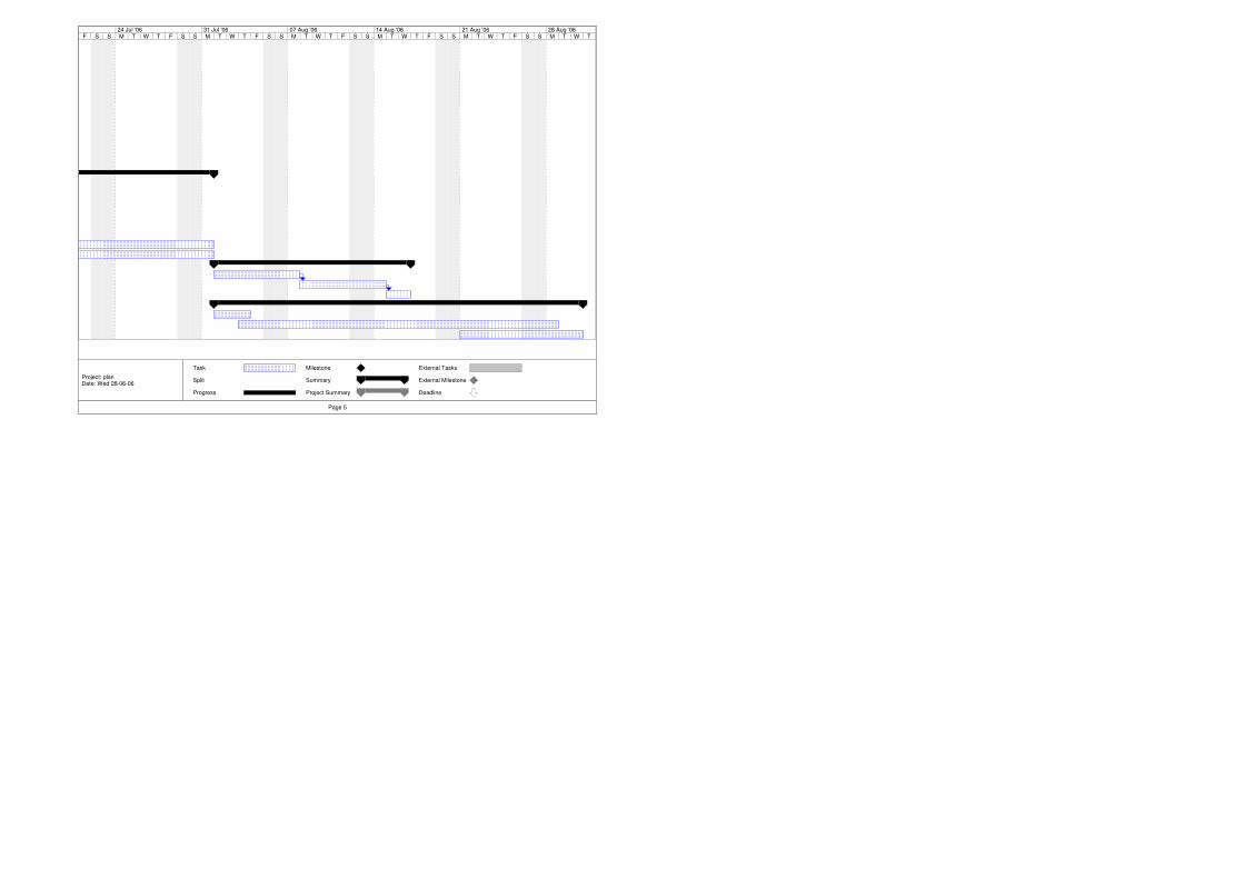
F S S M T W T F S S M T W T F S S M T W T F S S M T W T F S S M T W T F S S M T W T24 Jul '06 31 Jul '06 07 Aug '06 14 Aug '06 21 Aug '06 28 Aug '06
Task
Split
Progress
Milestone
Summary
Project Summary
External Tasks
External Milestone
Deadline
Page 5
Project: planDate: Wed 28-06-06


APPENDIX B. USER INTERFACE PROTOTYPES
Appendix B
User interface prototypes
59

APPENDIX B. USER INTERFACE PROTOTYPES
(a) Front page interface (b) Manage tests interface
(c) Manage areas interface (d) Manage campaigns interface
(e) View campaign executions (f) View campaign details interface
Figure B.1: User interface prototypes
60

APPENDIX C. EDGEBOX FLEUR
Appendix C
Edgebox Fleur
61
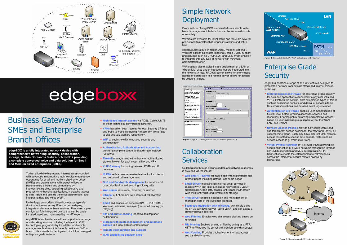
Today, affordable high-speed internet access coupled with advances in networking technologies create a new opportunity for small and medium sized enterprises (SMEs) and organisations with branch offices to become more efficient and competitive by interconnecting sites, deploying collaborative and productivity-enhancing applications, increasing access to data inside and outside the office (teleworkers) and integrating data and voice (VoIP).
Unlike large enterprises, these businesses typically don’t have the necessary IT resources to deploy, integrate and manage these services. They need a pre-configured, fully integrated device that can be easily installed, used and maintained by non-IT experts.
edgeBOX is such a device with a comprehensive range of networking services including the latest in VoIP technologies, plug-and-play installation and remote management features, it is the only device an SME or branch office needs for deployment of a fully converged enterprise grade network.
� High speed internet access via ADSL, Cable, UMTS, or other technology converted to Ethernet.
� VPNs based on both Internet Protocol Security (IPSec) and Point-to-Point-Tunnelling-Protocol (PPTP) for site-to-site and tele-workers respectively.
� WiFi at each site with integrated security and authentication
� Authentication, Authorisation and Accounting providing complete control and auditing of network resources
� Firewall management, either basic or authenticated stateful firewall for each external link and VPN
� VoIP Gateway for routing between PSTN and IP networks
� IP PBX with a comprehensive feature list for inbound and outbound call management
� QoS and Bandwidth Management for service and user prioritisation and ensuring voice quality
� Web server for intranet, extranet, or internet.
� Intranet out-of-the-box with standard collaborative services
� Email and associated services (SMTP, POP, IMAP, Webmail, anti-virus, anti-spam) for email hosting (or relaying)
� File and printer sharing for office desktop user collaboration.
� Storage with quota management and automatic backup to a local disk or remote server
� Remote configuration and support
� WAN capabilities between sites
Business Gateway for SMEs and Enterprise Branch Offices
edgeBOX is a fully integrated network device with comprehensive networking, security, collaboration, storage, built-in QoS and a feature-rich IP-PBX providing a complete converged voice and data solution for Small and Medium sized Enterprises (SMEs)
BBBeeesssttt BBBrrroooaaadddbbbaaannnddd
AAApppppp lll iii aaannnccceee 222000000555
Every feature of edgeBOX is controlled via a simple web-based management interface that can be accessed on-site or remotely.
Wizards are available for initial setup and there are several pre-defined templates that reduce installation and setup time
edgeBOX has a built-in router, ADSL modem (optional), Wireless access point card (optional), cable UMTS support and services such as DHCP, NAT and DNS which enable it to integrate into any type of network with minimum administration effort.
WiFi support also enables instant deployment of a LAN at “Greenfield” sites and of hot-spots that are integrated into the network. A local RADIUS server allows for anonymous access or connection to a remote server allows for access by account holders.
Figure 1: edgeBOX 100% java and web-based management GUI
Simple Network Deployment
Figure 3: Illustrative edgeBOX deployment scenario
Enterprise Grade Security edgeBOX contains a range of security features designed to protect the network from outside attack and internal misuse, including:
� Stateful Inspection Firewall for enterprise-grade security for data and applications connected via physical links and VPNs. Protects the network from all common types of threat such as suspicious packets, and denial of service attacks. Customisation options and detailed event logs included
� Authentication at Firewall enables user authentication at firewall level before granting access to services and resources. Enables policy enforcing and selective access based on user/machine/group separately for the WAN, LAN, and EWAN.
� Network Access Policies provide fully configurable and audited internet access policies for the WAN and EWAN by user/machine/group. Each may have different QoS classes, access restricted to specific time periods, restrictions on service access (e.g. VoIP, mail, web).
� Virtual Private Networks (VPNs) with IPSec allowing the secure connection of private networks through the internet cith 3DES encryption and MD5 authentication. PPTP Connections enable the establishment of VPN tunnels across the internet for secure remote access by teleworkers.
Collaboration through sharing of data and network resources is provided via the inbuilt:
� Web and FTP Server for easy deployment of intranet and internet pages including default user home pages
� Email Server maintains full internal email services in cases of WAN link failure. Includes relay control, LDAP authentication, ban lists, aliases, anti-spam, POP, IMAP, Web-mail, anti-virus, and remote mail storage
� Print Server Enables installation and management of shared printers at the customer premises
� Seamless integration with Windows, with single-point log-on via Windows Server (using LDAP) and can act as a primary domain controller
� Web Filtering Enables web site access blocking based on keywords
� File Sharing Enables sharing of files by acting as a FTP, HTTP or Windows file server with configurable disk quotas
� Web Caching Provides cached content for fast access and bandwidth saving.
Collaboration Services
Figure 2: Connects to the LAN, WAN and acts as a VoIP Gateway
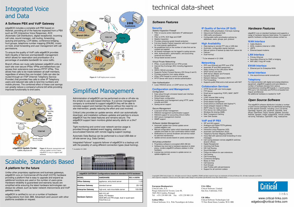
A platform for the future
Unlike other proprietary appliances and business gateways, edgeBOX runs on Commercial-off-the-shelf (COTS) hardware providing a platform that is easy to upgrade and expand as additional functions are used or the number of users grow. Hardware reliability is guaranteed and warranty issues are simplified while ensuring the latest hardware technologies can always be utilised, such as faster network interconnects and VoIP gateway cards.
edgeBOX is certified to run on a number of hardware configurations from Dell, IBM, Advantech and Lexcom with other platforms available on request.
Administration of edgeBOX can be performed on-site or off-site via the simple-to-use web based interface. If a service management company is contracted to support edgeBOX they will be able to remotely support and maintain the device without the need for on-site intervention, greatly reducing the effort and cost involved.
Critical Links provides an update service, which can automatically download, and installation software updates and patches to ensure edgeBOX has the latest features and remains secure. The edgeBOX support team monitors global security alerts on a 24x7 basis.
Tight monitoring and control over network service usage is provided through detailed event logging, statistics and accumulated histories with remote logging support (syslog).
Automatic Data Backup can be performed to a local USB-disk or off-site server (e.g. Data Center).
Integrated Failover* supports failover of edgeBOX to a backup unit with the possibly of using different connection types (dual-homing).
A Business Gateway for Small and Medium Sized businesses
Simplified Management
Integrated Voice and Data A Software PBX and VoIP Gateway
edgeBOX includes a complete soft PBX based on Asterisk, providing all of the features expected from a PBX such as IVR (Interactive Voice Response), ACD (Automatic Call Distribution), digital receptionist, incoming call rules, sound manager, call routing, forwarding, queuing and parking, LCR tables, conference bridging, hunt groups, telephone number mapping (ENUM), music-on-hold, email forwarding and user management with call permissions.
To ensure the quality of VoIP calls edgeBOX provides QoS (Quality of Service) and bandwidth management which allows for reservation and prioritisation of a percentage of available bandwidth for voice traffic.
Branch offices can route calls between edgeBOX units at each site over secure IPSec VPNs and teleworkers can access their extensions over secure PPTP VPNs. This allows free calls to be made between all staff members, regardless of where they are located. Calls can also be routed through an ITSP (Internet Telephony Service Provider) that provides free calls to other IP Telephony users and reduced rate calls to land line numbers and mobile phones. The combined effect of these cost savings can greatly reduce a company’s phone bill while providing improved functionality to end-users.
Scalable, Standards Based
* Available Q1 2006
Figure 4: VoIP deployment scenario
Figure 4: Remote management and
software update services mean
edgeBOX is easy to support and
maintain
MODEL HARDWARE REC # USERS
Office Gateway appliance, entry-level server 1-20
Business Gateway standard server 20-100
Enterprise Gateway high-end, rack-mountable server 100-500
Hardware Options
edgeBOX GATEWAY Configurations based on standard COTS hardware
WiFi PCI AP
ADSL PCI Modem
ISDN BRI and PRI single, dual or quad span
FXO/FXS 2+2
Software Features Security Stateful Inspection Firewall • Filter on source and/or destination IP address/port
value
• Filter on SYN, ACK flags and ICMP
• Stateful inspection
• Provides enterprise-grade firewall protection
• Full-time Stateful Packet Inspection with built-in support for most popular applications
• No predefined limit on the number of rules that can be created and applied
• All firewall messages can be logged to syslog servers
• AAA, Authentication, authorisation, and accounting (external and internal)
• Group based access control
Virtual Private Networking • IPSec, no pre-defined limit on VPN tunnels
• Internet Key Exchange (IKE) including Aggressive Mode
• 3DES (168-bit) encryption
• Supports Perfect Forward Secrecy (DH Group 2 and 5)
• Provides protection from replay attacks
• IPSec VPN Firewall to control tunnel access
• PPTP Server with local or remote authentication
User Authentication • Local, RADIUS server, or LDAP server (e.g. W2K)
Configuration and Management Configuration
• Easy setup through a browser-based user interface
• Wizard based setup
• Default basic configuration
• Configuration and management using HTTP, serial console and SSH
• Syslog server support
Secure Management • Local and remote management
• RADIUS management authentication support
• RADIUS support for accounting (time & traffic)
• SSH secure management channel
• SNMP support
Software Update Management • Automatic update from central update server
(update.edgebox.net)
• Manual configuration option which downloads available updates and waits for user confirmation before install
• Notifications for service shutdown and service restart for planned maintenance
• Update service access based on yearly subscription
Anti-piracy protection • Proprietary software is encrypted (AES 256 bit)
• Software key lock tied to hardware signature to deter piracy, renders edgeBOX software useless in other hardware
• License key controls access to update server on update.edgebox.net
IP Quality of Service (IP QoS) • DiffServ traffic prioritisation (ToS byte marking)
• Inbound and Outbound QoS
• CBQ traffic prioritisation
• Configurable traffic prioritisation policies by: addresses, users, groups, port, protocol
High Availability • Data backup to remote FPT site or USB disk
• Automatic, configurable regular backups
• Manual restore of backed up data from restore list
• Failover *
• Dual-homing* * To be released in Q1 2006
Networking • PPP over Ethernet and PPP over ATM
• Automatic IP and DNS assignment
• Static routing on the LAN and/or WAN
• DHCP server and client
• DNS Server (Master and Forward)
• Dynamic DNS client
• Network Address Translation (NAT)
• Port Forwarding
• Supports public Web and e-mail servers with NAT
Collaboration Services • HTTP Server with user home pages
• FTP Server
• Email server supporting: POP3, IMAP, SMTP
• Web mail
• LDAP Intranet Mail routing
• Email remote storage
• Email aliases management
• Email antivirus (interfaces with Sophos)
• Email antispam (based on RBLs)
• SMTP relay for road warriors
• Print Server (for USB printers)
• Windows file sharing (SME)
• Web Transparent Caching
• User Disk Quotas
VoIP and IP PBX • SIP and IAX support
• Analogue and Digital PSTN gateway
• Least Cost Routing
• Interactive Voice Response (IVR)
• Automatic Call Distribution (ACD)
• Telephone Number Mapping (ENUM)
• Voice Mail with optional email forwarding of voice messages
• Call routing between remote edgeBOX switches (branch offices)
• Digital Receptionist
• Incoming Call Rules
• DID Call Routing
• Sound Manager
• Follow-me feature for user extensions
• Call Parking
• Call Forwarding
• Conference Bridging
• Music on Hold
• Call Queuing
• Hunt Groups
• User Profiles with call permissions
• Support for all common codecs
European Headquarters
Critical Links, S.A.
Parque Industrial de Taveiro, Lote 48,
3045-504 Coimbra, Portugal
Tel +351 239 989 100 Fax +351 239 989 119
Lisbon Office
Critical Software, S.A, Polo Tecnológico de Lisboa
USA Office
Critical Software, Limited
San Jose, California, USA
UK Office
Critical Software Technologies Ltd
72 New Bond Street, London, W1S 1RR
www.critical-links.com [email protected]
technical data-sheet
Hardware Features edgeBOX runs on standard hardware and supports a range of hardware features listed below. For support of specific hardware configurations please contact us.
WAN Interface • Cable Modems
• ADSL modems (internal or USB)
• UMTS
• Ethernet-based modems
LAN Interface • Primary Ethernet
• Secondary Ethernet for DMZ or bridging
• WiFi (802.11b/g) AP mode
EWAN Interface • Ethernet port for Enterprise WAN
Serial Interface • One asynchronous serial console port
Telephony For interconnection with digital and analog telephony equipment, edgeBOX supports and auto-detects a number of hardware devices from various manufacturers including BRI boards (1, 4 and 8 ports), PRI (up to 124 channels) and POTS 2+2 boards from Digium and Beronet. No additional hardware is needed for VoIP.
Open Source Software The edgeBOX software distribution includes a number of open-source packages that are distributed according to their specific licenses, including: Linux 2.6 kernel, Openldap, Apache, php, sendmail, OpenSSL, bind, dhcpd, OpenSwan, Squid, Samba, Iptables, Iproute2, Asterisk, qpopper, imapd, postgreSQL, tomcat, proftpd, net-snmp, freeradius, OpenSSH, mrtg, mailscanner.
Copyright 2006 Critical Links S.A. All rights reserved. Critical, edgeBOX, iTEMS and their respective logos are trademarks of Critical Software SA. All other trademarks are held by
their respective companies. Critical reserves the right to make changes to the product specifications at any time without notice.


APPENDIX D. CD
Appendix D
CD
65