analysis, design and control of a unified power-quality
TRANSCRIPT

www.ijatir.org
ISSN 2348–2370
Vol.10,Issue.05,
May-2018,
Pages:0584-0589
Copyright @ 2018 IJATIR. All rights reserved.
Analysis, Design and Control of a Unified Power-Quality Conditioner
Based On a Current-Source Topology N. OBULESU
1, K. NAGAVENI
2, T. MANOHAR
3
1Assistant Professor, Dept of EEE, ALITS, Anantapur, AP, India.
2Assistant Professor, Dept of EEE, ALITS, Anantapur, AP, India.
3Assistant Professor, Dept of EEE, ALITS, Anantapur, AP, India.
Abstract: A three-phase unified power quality conditioner
based on current source converters (CSC-UPQC), including
the design guidelines of the key components, an appropriate
control scheme, and a selection procedure of the dc current
level. Particularly, the ride through capability criterion is
used to define a minimum dc current level so that the CSC-
UPQC achieves the same characteristics as a UPQC based
on voltage-source converters in terms of voltage disturbance
compensation in the point of common coupling (PCC) and
load power factor compensation. A series inverter of UPQC
is controlled to perform simultaneous 1) voltage sag/swell
compensation and 2) load power sharing with the shunt
inverter. The active power control is used to compensate
voltage sag/swell and is integrated with theory of power
angle control of UPQC to coordinate the load reactive
power between the two inverters. Since series inverters
simultaneously deliver active and reactive powers, this
concept is named as UPQC-S (S for complex power). A
detailed mathematical analysis, to extend the PAC approach
for UPQC-S is presented in this project A 1.17 MVA load
fed from a 3.3 kV system is used to show the proposed
design procedure, and a laboratory prototype is
implemented to show the system compensating sags and
swells using low switching frequency in the CSC and
maintaining a unitary displacement power factor in the
PCC.
Keywords: Current Source Converters, Nonlinear Control,
Power Quality (PQ), Unified Power-Quality Conditioner
(UPQC).
I. INTRODUCTION
The present power distribution system is becoming highly
susceptible to the different power quality issues. The wide-
ranging use of nonlinear loads is further causal to greater
than before current and voltage harmonic problems. In
addition, the saturation stage of small/large-scale renewable
energy systems (RES) base on wind energy, solar radiation
energy, chemical fuel cell, etc., installs at distribution and
transmission levels is rising fundamentally. In addition of
renewable energy sources in a power system are further
magnificent new difficult task to the electrical industry to
include these newly rising distributed generation systems.
To continue the controlled power quality regulations, some
kinds of compensation at all the power levels are becoming
a familiar perform. The provision of both DSTATCOM and
DVR can control the power quality of the source current and
the load bus voltage. In addition, if the DVR and
STATCOM are connected on the DC side, the DC bus
voltage can be regulated by the shunt connected
DSTATCOM while the DVR supplies the required energy
to the load in case of the transient disturbances in source
voltage. The configuration of such a device (termed as
Unified Power Quality Conditioner (UPQC)) is shown. This
is a versatile device similar to a UPFC. However, the
control objectives of a UPQC are quite different from that of
a UPFC.
Fig.1. UPQC Operation of D-Statcom.
In view of both voltages sag and swell scenarios are
essential for a detailed investigation on VA loading in
UPQC-VA min as shown in Fig.1. The authors have
proposed in the project a concept of Power Angle Control
(PAC) of UPQC. The Power Angle Control idea suggest
that with good control of the series inverter voltage
successfully supports the part of the load reactive power
demand, and thus the VA rating of the shunt inverter
reduces. Most significantly, this synchronize reactive power
sharing feature is achieved without disturbing the resultant
load voltage magnitude, during normal steady-state
condition. Using particle swarm optimization technique the
optimal angle of series voltage injection in UPQC-VA min
is computed. These iterative like methods mostly on the
online load power factor (PF) angle evaluation, and thus
may result into deadly and slower evaluation of optimal
angle.

N. OBULESU, K. NAGAVENI, T. MANOHAR
International Journal of Advanced Technology and Innovative Research
Volume. 10, IssueNo.05, May-2018, Pages: 0584-0589
II. POWER QUALITY
Conceivably, the best electrical supply would be a steady
greatness and frequency sinusoidal voltage waveform. On
account of the non-zero impedance of the supply
framework, of the expansive assortment of loads that may
be experienced and of other phenomena, for example,
transients and outages, the truth is regularly diverse. The
Power Quality of a system communicates to which degree a
practical supply system looks like the perfect supply system.
Poor Power Quality can be depicted as any occasion
identified with the electrical system network that ultimately
results in a budgetary misfortune. Conceivable results of
poor Power Quality incorporate
Unexpected power supply failures (breakers tripping,
wires blowing).
Equipment failure or failing
Equipment overheating (transformers, engines) are
prompting their lifetime reduction.
Damage to delicate supplies (Pc‘s, production line
control frameworks).
Electronic communication interferences
Increase of system power losses
A. Definition Of Power Quality Power quality could be a term which means various things
to completely different individuals. Institute of Electrical
and Electronic Engineers (IEEE) normal IEEE1100 defines
power quality as “the conception of powering and
grounding sensitive instrumentation equipment in an
exceedingly manner appropriate for the equipment. All
electrical devices are prone to malfunction or failure when
exposed to more power quality problems. The electrical
machine be a transformer, an electric motor, a computer a
generator, a printer, a household appliance, or a
communication equipment. Depending on the severity of
problems others and all of these devices react adversely to
power quality issues as shown in Fig.2.
B. Power Quality Progression
Since the invention of power 300 years ago, the
distribution, generation and use of electricity have correctly
evolved. New and innovative suggest to generate and use
electricity the economic revolution, and since then
engineers, scientists, and hobbyists have contributed to its
continued evolution. In the starting stage, electrical devices
and machines were crude at best but nonetheless more
utilitarian. They performed quite well and consumed gaint
amounts of electricity. The machines were designed with
price consideration solely secondary to performance issues
as shown in Fig.3. They were probably liable to however the
consequences were not readily discernible, whatever power
quality problems existed at the time, and due partly to the
robustness of the machines and due to the lack of good ways
to measure parameters of power quality. However, within
the last 50 years or so, the economic years to the need for
products which are to be economically competitive, that
meant that electrical machines were smaller and more
efficient and were designed without performance margins.
At a uniformity time, diverse variables were becoming
possibly the most important factor.
C. Power Quality Nomenclature
Webster’s New World Dictionary defines nomenclature as
the “the terms employed in a specific art science etc.”
Understanding the terms employed in any branch of
humanities or science is basic to developing a way of
familiarity with the topic. The science of power quality is
not any exception. Inter connecting the conductive parts
electrically to ensure common voltage between the
connected parts. Electrical bonding is done for two reasons.
When bonded using low impedance connections, conductive
parts, would be at the same electrical potential, which
means that the difference in voltage between the connected
parts would be negligible or minimal. Electrical Bonding
additionally states current likely imposed on a metal part
should be safely conducted to other grid systems or ground
serving as ground.
Fig.2. Distortion.
Fig.3 notch & noise.
Fig.4 voltage swell.
D. Power Quality Issues
Power quality is an easy term, nevertheless it describes
a different issue which are found in any electrical power
system network and it is a subjective term. The concept of
bad and good power depends on the end user. The consumer
feels that the power is good if a piece of equipment
functions satisfactorily. If the equipment fails prematurely
Analysis, Design and Control of a Unified Power-Quality Conditioner Based On a Current-Source Topology
International Journal of Advanced Technology and Innovative Research
Volume. 10, IssueNo.05, May-2018, Pages: 0584-0589
or does not function as intended there is a feeling that the
power will be bad. Depending on the perspective of the
power user In between these limits, many grades or layers
of power quality might exist as shown in Fig.4. A better
starting point for solving all /power quality problems is,
understanding the power quality issues. Power frequency
disturbances are low-frequency phenomena which results in
voltage swells or sags. They may be load or source
generated due to switching operations or faults in a power
system. The susceptibility of electrical equipment is
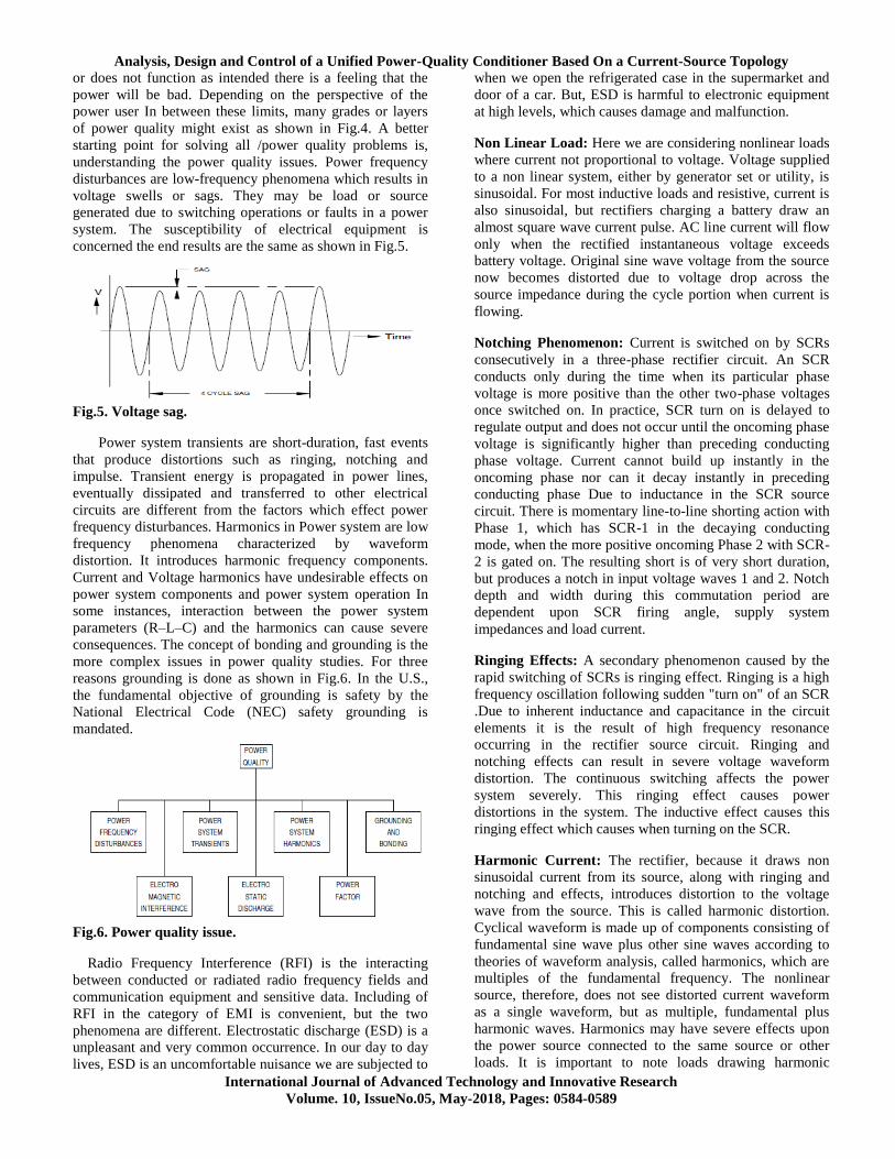
concerned the end results are the same as shown in Fig.5.
Fig.5. Voltage sag.
Power system transients are short-duration, fast events
that produce distortions such as ringing, notching and
impulse. Transient energy is propagated in power lines,
eventually dissipated and transferred to other electrical
circuits are different from the factors which effect power
frequency disturbances. Harmonics in Power system are low
frequency phenomena characterized by waveform
distortion. It introduces harmonic frequency components.
Current and Voltage harmonics have undesirable effects on
power system components and power system operation In
some instances, interaction between the power system
parameters (R–L–C) and the harmonics can cause severe
consequences. The concept of bonding and grounding is the
more complex issues in power quality studies. For three
reasons grounding is done as shown in Fig.6. In the U.S.,
the fundamental objective of grounding is safety by the
National Electrical Code (NEC) safety grounding is
mandated.
Fig.6. Power quality issue.
Radio Frequency Interference (RFI) is the interacting
between conducted or radiated radio frequency fields and
communication equipment and sensitive data. Including of
RFI in the category of EMI is convenient, but the two
phenomena are different. Electrostatic discharge (ESD) is a
unpleasant and very common occurrence. In our day to day
lives, ESD is an uncomfortable nuisance we are subjected to
when we open the refrigerated case in the supermarket and
door of a car. But, ESD is harmful to electronic equipment
at high levels, which causes damage and malfunction.
Non Linear Load: Here we are considering nonlinear loads
where current not proportional to voltage. Voltage supplied
to a non linear system, either by generator set or utility, is
sinusoidal. For most inductive loads and resistive, current is
also sinusoidal, but rectifiers charging a battery draw an
almost square wave current pulse. AC line current will flow
only when the rectified instantaneous voltage exceeds
battery voltage. Original sine wave voltage from the source
now becomes distorted due to voltage drop across the
source impedance during the cycle portion when current is
flowing.
Notching Phenomenon: Current is switched on by SCRs
consecutively in a three-phase rectifier circuit. An SCR
conducts only during the time when its particular phase
voltage is more positive than the other two-phase voltages
once switched on. In practice, SCR turn on is delayed to
regulate output and does not occur until the oncoming phase
voltage is significantly higher than preceding conducting
phase voltage. Current cannot build up instantly in the
oncoming phase nor can it decay instantly in preceding
conducting phase Due to inductance in the SCR source
circuit. There is momentary line-to-line shorting action with
Phase 1, which has SCR-1 in the decaying conducting
mode, when the more positive oncoming Phase 2 with SCR-
2 is gated on. The resulting short is of very short duration,
but produces a notch in input voltage waves 1 and 2. Notch
depth and width during this commutation period are
dependent upon SCR firing angle, supply system
impedances and load current.
Ringing Effects: A secondary phenomenon caused by the
rapid switching of SCRs is ringing effect. Ringing is a high
frequency oscillation following sudden "turn on" of an SCR
.Due to inherent inductance and capacitance in the circuit
elements it is the result of high frequency resonance
occurring in the rectifier source circuit. Ringing and
notching effects can result in severe voltage waveform
distortion. The continuous switching affects the power
system severely. This ringing effect causes power
distortions in the system. The inductive effect causes this
ringing effect which causes when turning on the SCR.
Harmonic Current: The rectifier, because it draws non
sinusoidal current from its source, along with ringing and
notching and effects, introduces distortion to the voltage
wave from the source. This is called harmonic distortion.
Cyclical waveform is made up of components consisting of
fundamental sine wave plus other sine waves according to
theories of waveform analysis, called harmonics, which are
multiples of the fundamental frequency. The nonlinear
source, therefore, does not see distorted current waveform
as a single waveform, but as multiple, fundamental plus
harmonic waves. Harmonics may have severe effects upon
the power source connected to the same source or other
loads. It is important to note loads drawing harmonic

N. OBULESU, K. NAGAVENI, T. MANOHAR
International Journal of Advanced Technology and Innovative Research
Volume. 10, IssueNo.05, May-2018, Pages: 0584-0589
currents causes voltage distortion at the source ,the source
does not produce the harmonic distortion.
Power Factor: Generators are rated for 0.8 power factor.
Connected loads may have a lower power factor.
Displacement of current with respect to voltage occurs with
rectifier phase control. Line power factor can vary
depending upon SCR conduction angle. Compounding this
are the high frequency harmonic currents which primarily
result in added KVAR. Consult with the device supplier for
specific input KVA and power factor.
III. PROPOSED SYSTEM
In distribution level, to compensate several major power
quality problems UPQC is a main clarification. In figure the
general block diagram representation of a UPQC-based
system is shown. It normally consists of two voltage source
inverters associated back to back using a general dc bus
capacitor. This project deals with a new concept of most
select utilization of a UPQC. The most important power
quality problems are voltage sag & swell on the system. The
voltage sag/swell will be compensated by the devices of a,
series active power filters, dynamic voltage restorer, UPQC,
etc. as well as with the help of power quality enhancement
devices, the UPQC has higher compensation capability for
voltage problems such as sag/swell. In this project called as
UPQC-VA min. along with the aforementioned the three
approaches, the in-phase voltage injection requires the
minimum voltage magnitude, while the quadrature voltage
injections require a maximum series injected voltage. For
the duration of a minimum VA loading approach, the series
inverter injects the voltage at an certain angle with respect
to the source current. As well the series inverter injection,
the current drawn by the shunt inverter from the network, to
maintain the dc link voltage and the highly power balance in
the network, and plays an vital role in obtaining the overall
UPQC VA loading as shown in Fig.7.
Fig.7. Structure of Unified Power Quality Conditioner
(UPQC) system.
The project on UPQC-VA min is obtained on the optimal
VA loading of the series & shunt inverter of UPQC mainly
during voltage sag/swell condition. while it is necessary an
out of phase module to be injected for compensation of
voltage swell, the recommended VA loading in UPQC-VA
min obtained on the basis of the voltage sag, It could not be
at optimal value. In view of both voltages sag and swell
scenarios are essential for a detailed investigation on VA
loading in UPQC-VA min. The authors have proposed in
the project a concept of Power Angle Control (PAC) of
UPQC. The Power Angle Control idea suggest that with
good control of the series inverter voltage successfully
supports the part of the load reactive power demand, and
thus the VA rating of the shunt inverter reduces. Most
significantly, this synchronize reactive power sharing
feature is achieved without disturbing the resultant load
voltage magnitude, during normal steady-state condition.
Using particle swarm optimization technique the optimal
angle of series voltage injection in UPQC-VA min is
computed. These iterative like methods mostly on the online
load power factor (PF) angle evaluation, and thus may result
into deadly and slower evaluation of optimal angle. On the
other hand, by estimating the power angle δ, the PAC of
UPQC concept determines the series injection angle. The
angle δ is compute in adaptive way by computing the instant
load active/reactive power and thus, it ensures fast and exact
estimation. With similar to PAC of UPQC, In a unified
power flow controller (UPFC) the reactive power flow
control utilizes by shunt and series inverters as shown in
Fig.8. A UPQC is used in a power distribution system to
carry out the shunt and series compensation at the same
time, while a UPFC is used in a power transmission system.
In balanced and distortion-free environment, the power
transmission systems are generally operated, unlike to
power distribution systems that may contain dc component,
distortion, and unbalance. The main purpose of a UPFC is to
control the flow of power at fundamental frequency.
Fig.8. Concept of PAC of UPQC.
In this project, a total mathematical formulation of PAC
for UPQC-S is carried out. The prospect and efficiency of
the proposed UPQC-S approach are validates by simulation
as well as experimental results. Also, this power flow
control in UPFC the transmission network voltage may not
be maintained at the rated value while at the stage.
However, the load side voltage is strictly regulated at rated
value in PAC of UPQC, while performing load reactive
power sharing by shunt and series inverters. In this project,
the model of PAC of UPQC is further extended for voltage
sag and swells conditions. This modified model come
within reach of is utilized to compensate voltage sag/swell
while sharing the load reactive power between both shunt &
series inverters. Since in this case the series inverter of
UPQC delivers both active and reactive powers, it is
particular the name UPQCS (S for complex power). The key
in assistance of this project are outline as follows.

Analysis, Design and Control of a Unified Power-Quality Conditioner Based On a Current-Source Topology
International Journal of Advanced Technology and Innovative Research
Volume. 10, IssueNo.05, May-2018, Pages: 0584-0589
For simultaneous voltage sag/swell and load reactive
power compensation in network with shunt inverter, the
series inverter of UPQC-S is utilized.
In UPQC-S, the available VA loading is utilized to its
maximum capacity during the entire running situation
opposing to UPQC-VA min where prime focus is to
reduce the VA loading of UPQC during voltage sag
condition.
The voltage sags as well as swells situation covers by
the concept of UPQC-S.
IV. SIMULATION RESULTS
Simulation results of this paper is as shown in bellow
Figs.9 to 19.
Fig.9. Supply voltage.
Fig.10. Load voltage.
Fig.11. Series inverter injected voltage.
Fig.12. Series inverter current.
Fig.13. Self-supporting dc bus voltage.
Fig.14. Enlarged power angle δ relation between supply
and load voltages during steady-state condition.
Fig.15. Supply current.
Fig.16 Load current.
Fig.17 Shunt inverter injected current.
N. OBULESU, K. NAGAVENI, T. MANOHAR
International Journal of Advanced Technology and Innovative Research
Volume. 10, IssueNo.05, May-2018, Pages: 0584-0589
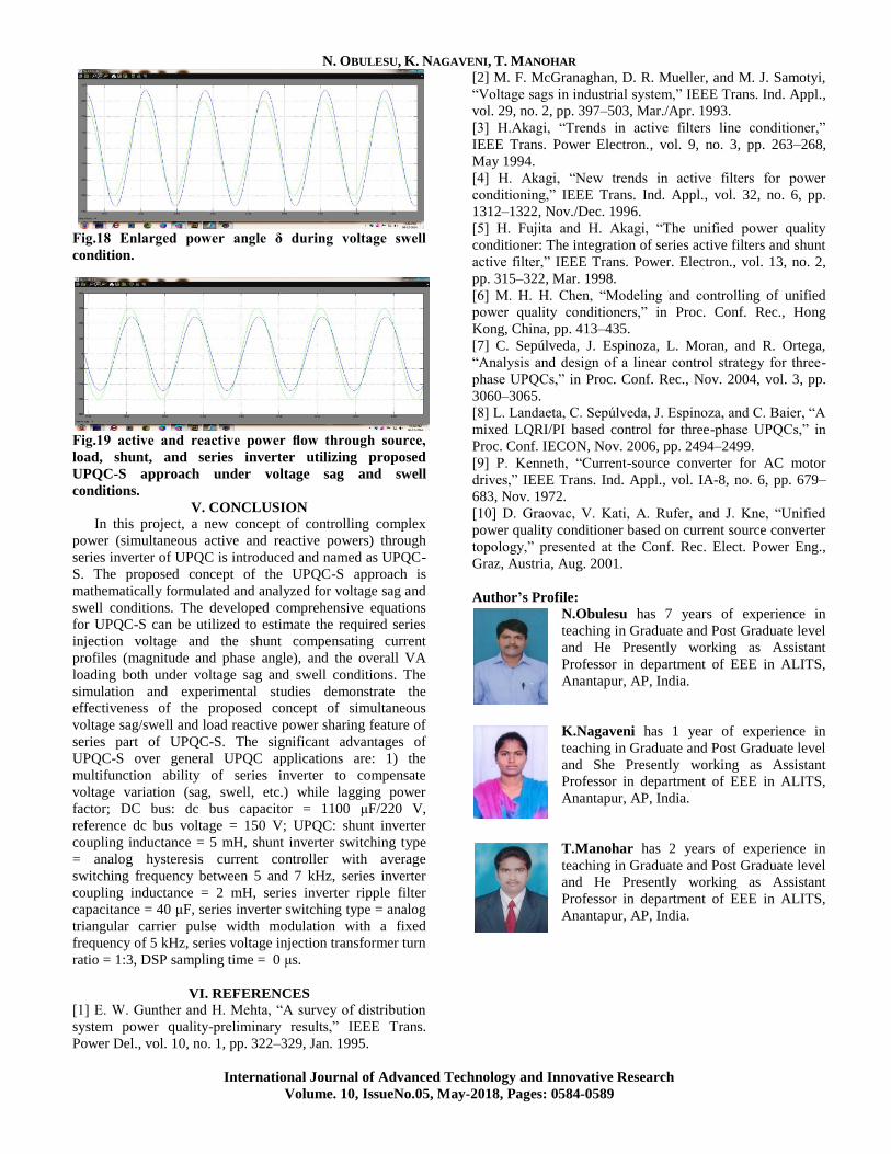
Fig.18 Enlarged power angle δ during voltage swell
condition.
Fig.19 active and reactive power flow through source,
load, shunt, and series inverter utilizing proposed
UPQC-S approach under voltage sag and swell
conditions.
V. CONCLUSION
In this project, a new concept of controlling complex
power (simultaneous active and reactive powers) through
series inverter of UPQC is introduced and named as UPQC-
S. The proposed concept of the UPQC-S approach is
mathematically formulated and analyzed for voltage sag and
swell conditions. The developed comprehensive equations
for UPQC-S can be utilized to estimate the required series
injection voltage and the shunt compensating current
profiles (magnitude and phase angle), and the overall VA
loading both under voltage sag and swell conditions. The
simulation and experimental studies demonstrate the
effectiveness of the proposed concept of simultaneous
voltage sag/swell and load reactive power sharing feature of
series part of UPQC-S. The significant advantages of
UPQC-S over general UPQC applications are: 1) the
multifunction ability of series inverter to compensate
voltage variation (sag, swell, etc.) while lagging power
factor; DC bus: dc bus capacitor = 1100 μF/220 V,
reference dc bus voltage = 150 V; UPQC: shunt inverter
coupling inductance = 5 mH, shunt inverter switching type
= analog hysteresis current controller with average
switching frequency between 5 and 7 kHz, series inverter
coupling inductance = 2 mH, series inverter ripple filter
capacitance = 40 μF, series inverter switching type = analog
triangular carrier pulse width modulation with a fixed
frequency of 5 kHz, series voltage injection transformer turn
ratio = 1:3, DSP sampling time = 0 μs.
VI. REFERENCES
[1] E. W. Gunther and H. Mehta, “A survey of distribution
system power quality-preliminary results,” IEEE Trans.
Power Del., vol. 10, no. 1, pp. 322–329, Jan. 1995.
[2] M. F. McGranaghan, D. R. Mueller, and M. J. Samotyi,
“Voltage sags in industrial system,” IEEE Trans. Ind. Appl.,
vol. 29, no. 2, pp. 397–503, Mar./Apr. 1993.
[3] H.Akagi, “Trends in active filters line conditioner,”
IEEE Trans. Power Electron., vol. 9, no. 3, pp. 263–268,
May 1994.
[4] H. Akagi, “New trends in active filters for power
conditioning,” IEEE Trans. Ind. Appl., vol. 32, no. 6, pp.
1312–1322, Nov./Dec. 1996.
[5] H. Fujita and H. Akagi, “The unified power quality
conditioner: The integration of series active filters and shunt
active filter,” IEEE Trans. Power. Electron., vol. 13, no. 2,
pp. 315–322, Mar. 1998.
[6] M. H. H. Chen, “Modeling and controlling of unified
power quality conditioners,” in Proc. Conf. Rec., Hong
Kong, China, pp. 413–435.
[7] C. Sepúlveda, J. Espinoza, L. Moran, and R. Ortega,
“Analysis and design of a linear control strategy for three-
phase UPQCs,” in Proc. Conf. Rec., Nov. 2004, vol. 3, pp.
3060–3065.
[8] L. Landaeta, C. Sepúlveda, J. Espinoza, and C. Baier, “A
mixed LQRI/PI based control for three-phase UPQCs,” in
Proc. Conf. IECON, Nov. 2006, pp. 2494–2499.
[9] P. Kenneth, “Current-source converter for AC motor
drives,” IEEE Trans. Ind. Appl., vol. IA-8, no. 6, pp. 679–
683, Nov. 1972.
[10] D. Graovac, V. Kati, A. Rufer, and J. Kne, “Unified
power quality conditioner based on current source converter
topology,” presented at the Conf. Rec. Elect. Power Eng.,
Graz, Austria, Aug. 2001.
Author’s Profile:
N.Obulesu has 7 years of experience in
teaching in Graduate and Post Graduate level
and He Presently working as Assistant
Professor in department of EEE in ALITS,
Anantapur, AP, India.
K.Nagaveni has 1 year of experience in
teaching in Graduate and Post Graduate level
and She Presently working as Assistant
Professor in department of EEE in ALITS,
Anantapur, AP, India.
T.Manohar has 2 years of experience in
teaching in Graduate and Post Graduate level
and He Presently working as Assistant
Professor in department of EEE in ALITS,
Anantapur, AP, India.