analysis and seismic isolation of an older reinforced ... and seismic isolation of an older...
TRANSCRIPT

Contemporary Engineering Sciences, Vol. 9, 2016, no. 25, 1201 - 1215
HIKARI Ltd, www.m-hikari.com http://dx.doi.org/10.12988/ces.2016.66110
Analysis and Seismic Isolation of an Older
Reinforced Concrete Vaulted Building
Stefano Sorace
Polytechnic Department of Engineering and Architecture
Via delle Scienze 206 33100 Udine, Italy
Gloria Terenzi
Department of Civil and Environmental Engineering
Via di S. Marta 3, 50139 Florence, Italy
Copyright © 2016 Stefano Sorace and Gloria Terenzi. This article is distributed under the
Creative Commons Attribution License, which permits unrestricted use, distribution, and
reproduction in any medium, provided the original work is properly cited.
Abstract
Reinforced concrete (R/C) structures designed with earlier Technical Standards
often require retrofit interventions to improve their performance capacities,
especially against seismic actions. A case study belonging to this class, i.e. the
swimming pool building of the Naval Academy in Leghorn, Italy, rebuilt in 1948
after being destroyed by air raids during the Second World War, is examined
herein. The structure of the main hall is constituted by a prefab R/C vaulted roof
designed by the world-famous Italian engineer Pier Luigi Nervi, supported by a
set of inclined columns with relatively small sections. The assessment analysis in
current conditions shows unsafe response conditions of these members, as well as
of several other columns and beams, under seismic action scaled at the basic
design earthquake level. In order to minimize the impact of the retrofit
intervention on the exposed structural elements, a base isolation solution is
proposed for the building. The verification analyses in protected conditions
highlight a substantial enhancement of the seismic response capacities of the
structure, with no intervention required in the elevation structure, up to the
maximum considered normative earthquake level.
Keywords: Older R/C structures, Seismic assessment; Base isolation
1 Introduction
The study of heritage-listed reinforced concrete (R/C) buildings, and particularly

1202 Stefano Sorace and Gloria Terenzi
the ones built in the so-called “golden age” period between the 1930s and the
1960s, is currently a challenging topic both in the fields of structural engineering
[1] and history and conservation of modern architecture [2].
From a structural viewpoint, these buildings highlight poor performance
capacities in comparison to the requirements of the latest normative generation,
especially regarding the response to seismic actions. This is generally checked in
terms of strength and ductility, and often translational stiffness, for frame
structures. In addition, a lack of redundancy is noticed in certain special structures,
including platform and vaulted roofs, arcades, stands, galleries, exhibition halls,
tanks, bell towers, etc, where the number of vertical members is kept to a
minimum and their cross sections are optimized in size, so as to improve the
effects of geometrical slenderness. This imposes to carry out careful structural
assessment analyses, as well as to plan seismic retrofit interventions, particularly
when these buildings are of public use [1,3–5].
A representative case study belonging to this class of special structures,
designed by the world-famous engineer Pier Luigi Nervi, is examined in this
paper. The building is the swimming pool of the Naval Academy in Leghorn, Italy,
whose first storey was rebuilt in 1948, after being destroyed by air raids during
the Second World War (Fig. 1).
Fig. 1. Views of the original building (1936) and its appearance after the Second
World War bombing (1945).
The distinguishing structural and architectural feature of the building is
represented by the barrel vault-shaped roof, constituted by thin prefab R/C curved
beams with smoothed-V wavy section, patented by Nervi during the construction
works (patent No. 445781 registered on August 26th, 1948). This type of beams
was adopted by the designer in the following decades for other roof vaults with
greater spans, the first time in the Exhibition Hall Palace in Turin, in 1949, so that
it has become a typical feature of the internationally recognized Nervi’s style.
The other main structural members, i.e. the R/C columns and beams
supporting the roof and the façade aisles — originally designed for gravitational
loads only and pursuing a minimal size philosophy with respect to the calculated
stress states — have small cross sections. This significantly contributes to the
architectural elegance of the building, which was included in the Italian modern

Analysis and seismic isolation 1203
heritage listing shortly after its construction. At the same time, these
characteristics can remarkably affect the seismic performance of the structural
system. Furthermore, the presence of a brick masonry stairwell wing situated in
eccentric position in plan determines noticeable torsional contributions to the
modal response of the building.
Based on these observations, a seismic assessment study was carried out in the
frame of a research line developed by the authors on modern heritage R/C
structures and infrastructures [1, 5]. The results highlight the unsafe response of
several members at the basic design earthquake level, and near-critical conditions at
the maximum considered earthquake level. An advanced retrofit hypothesis is
proposed to obtain safe response conditions up to the latter level. The solution
consists in incorporating a seismic isolation system on top of the columns bearing
the pool tank, and at the bottom of the columns of the pool hall and the stairwell and
entrance masonry wings. This allows minimizing the impact of the retrofit
intervention on the exposed structural elements, as well as exploiting the unusual
presence of a frame structure supporting the pool tank, originally built to protect it
against floods from the sea and from an adjacent stream.
A synthesis of the construction history of the building and its structural
characteristic, the results of the assessment analyses, and the base isolation retrofit
design hypothesis are presented in the next sections.
2 Construction history of the building
The construction works of the swimming pool building of the Naval Academy
started in 1934. The site is situated on Leghorn seaside, adjacent to the mouth of
Rio Maggiore stream. A preliminary reclamation of the site was carried out to
reach firmer soil conditions. A continuous R/C wall was built as retaining
structure, on the bank side, and as perimeter wall of the basement of the building,
on the seaside. The pool tank was built within this enveloping wall, supported by
an underlying R/C frame structure (Fig. 2). This uplifted position with respect to
the foundation soil was adopted to protect the pool tank against any possible
floods from the sea and the stream, as well as against the rise of groundwater.
The swimming pool building was provided with a R/C frame structure standing
on the box wall of the basement. The stairwell and entrance wings, situated in
lateral position with respect to the pool hall, have a brick masonry structure. The
stair flights are made of R/C slabs, supported by four R/C columns.
The bombings suffered by the Naval Academy in 1944 completely destroyed
the swimming pool hall, whereas the stairwell and entrance wings were only
slightly damaged (Fig. 1).

1204 Stefano Sorace and Gloria Terenzi
Fig. 2. Views of the construction works of the R/C basement and the pool tank, and
the completed under-pool structure (1935).
In the aftermath of the Second World War, the Italian Ministry of Defence
approved the reconstruction of the pool hall. The design was assigned to Pier
Luigi Nervi, who conceived a barrel vault-shaped R/C structure for the roof, with
span of 11.4 m, supported by a set of inclined columns. As mentioned in the
Introduction, the vault is constituted by thin prefab R/C curved beams with
smoothed-V wavy section (Fig. 3). The beams are 300 mm high and 50 mm thick,
with radius of curvature equal to 6.8 m and length equal to 1/2 of the vault span.
The reinforcement consists of a mesh of steel wires, integrated by a set of Ø5
longitudinal bars. A transversal R/C diaphragm and a ribbed contour are built at
both ends, to connect the beams one to another and to the supporting columns
during the installation works (Fig. 3). The connection is obtained by means of 4
Ø8 bars placed at the bottom of the V-shaped section, and 4 Ø8 bars on the two
top ribs, embedded in on-site integrative casts (for which the roof beams
constitute the formworks). A transversal diaphragm is located at the mid-span as
stiffening element in this direction, whereas the beams are stiffened by the two
continuous top ribs in longitudinal direction (Fig. 3).
Fig. 3. Original design drawing of a prefab R/C curved element of the barrel vault
roof, and views of the on-site manufacturing and installation works (1947-1948).
The structural plans of the under-pool, basement and ground floors, and the
longitudinal and transversal cross sections of the building are shown in Figs. 4 and
5, respectively. Over time, the building has been the object of routine maintenance
interventions only, mainly concerning waterproofing and technical plants. An
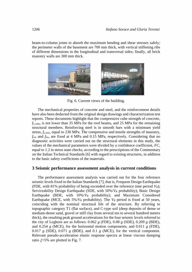
external and an internal view in current conditions are displayed in Fig. 6.

Analysis and seismic isolation 1205
Fig. 4. Structural plans of the under-pool, basement and ground floors (dimensions
in meters).
Fig. 5. Longitudinal and transversal cross sections (dimensions in meters).
The dimensions of the cross sections of the remaining structural elements are as
follows: the roof columns have a base of 250 mm and height varying from 400 mm,
at the bottom, to 600 mm, on top; the façade columns and stairwell columns have
mutual section of (250250) mmmm; the roof-supporting beams and the façade
beams have mutual section of (500400) mmmm and (250300) mmmm,
respectively; the under-pool columns have section of (500500) mmmm, except
for a set of perimeter elements situated below the deepest portion of the pool tank,
with section of (5001300) mmmm; the under-pool beams have sections of
(500400) mmmm or section of (400400) mmmm, enlarged in proximity to the
40.5
45.6
49.1
14.2
15.9
33.4
10
16.7
14.2
40.5
45.6
49.1
1206 Stefano Sorace and Gloria Terenzi
beam-to-column joints to absorb the maximum bending and shear stresses safely;
the perimeter walls of the basement are 700 mm thick, with vertical stiffening ribs
of different dimensions in the longitudinal and transversal sides; finally, all brick
masonry walls are 300 mm thick.
Fig. 6. Current views of the building.
The mechanical properties of concrete and steel, and the reinforcement details
have also been deducted from the original design drawings and characterization test
reports. These documents highlight that the compressive cube strength of concrete,
fc,cube, is not lower than 35 MPa for the roof beams, and 25 MPa for the remaining
structural members. Reinforcing steel is in smooth bars with a minimum yield
stress, fy,min, equal to 230 MPa. The compressive and tensile strengths of masonry,
fcm and ftm, are fixed at 4 MPa and 0.15 MPa, respectively. Considering that no
diagnostic activities were carried out on the structural elements in this study, the
values of the mechanical parameters were divided by a confidence coefficient, FC,
equal to 1.2 in stress state checks, according to the prescriptions of the Commentary
on the Italian Technical Standards [6] with regard to existing structures, in addition
to the basic safety coefficients of the materials.
3 Seismic performance assessment analysis in current conditions
The performance assessment analysis was carried out for the four reference
seismic levels fixed in the Italian Standards [7], that is, Frequent Design Earthquake
(FDE, with 81% probability of being exceeded over the reference time period VR);
Serviceability Design Earthquake (SDE, with 50%/VR probability); Basic Design
Earthquake (BDE, with 10%/VR probability); and Maximum Considered
Earthquake (MCE, with 5%/VR probability). The VR period is fixed at 50 years,
coinciding with the nominal structural life of the structure. By referring to
topographic category T1 (flat surface), and C-type soil (deep deposits of dense or
medium-dense sand, gravel or stiff clay from several ten to several hundred meters
thick), the resulting peak ground accelerations for the four seismic levels referred to
the city of Leghorn are as follows: 0.062 g (FDE), 0.08 g (SDE), 0.209 g (BDE),
and 0.254 g (MCE), for the horizontal motion components; and 0.011 g (FDE),
0.017 g (SDE), 0.071 g (BDE), and 0.1 g (MCE), for the vertical component.
Relevant pseudo-acceleration elastic response spectra at linear viscous damping
ratio =5% are plotted in Fig. 7.

Analysis and seismic isolation 1207
Fig. 7. Normative pseudo-acceleration elastic response spectra for the horizontal
and vertical earthquake components – Leghorn.
The time-history analyses were developed by assuming artificial ground
motions as inputs, generated in families of seven by SIMQKE-II software [8] from
the spectra above, both for the horizontal components (two families) and the
vertical one (one family). In each time-history analysis the accelerograms were
applied in groups of three simultaneous components, i.e. two horizontal
components, with the first one selected from the first generated family of seven
motions, and the second one selected from the second family, plus the vertical
component.
The finite element model of the structure was generated by SAP2000NL
program [9]. A perspective view of the model, reproducing the structural system in
elevation, is displayed in Fig. 8.
Fig. 8. View of the finite element model of the structure in elevation.
The frame structure bearing the pool tank and the perimeter R/C walls were
modelled separately, so as to restrain the dimensions of the mesh within reasonable
computational limits. Frame-type elements were adopted to model beams and
columns, and shell-type elements for the masonry walls of the stairwell and
entrance wings, and the end walls of the pool hall.
A modal analysis of the structure was preliminarily carried out, and showed that
all main vibration modes are mixed translational, along the longitudinal and transversal
0 0.5 1 1.5 2 2.5 3 3.5 4 0
0.1
0.2
0.3
0.4
0.5
0.6
0.7
0.8
0.9
1
Leghorn Vertical Component
=5% VN=50 years
TC=T1 C-Type Soil
Pseudo-A
ccele
ratio
n [g]
BDE
SDE
MCE
FDE
Period [s]
0 0.5 1 1.5 2 2.5 3 3.5 4 0
0.1
0.2
0.3
0.4
0.5
0.6
0.7
0.8
0.9
1
Leghorn Horizontal Component
=5% VN=50 years
TC=T1 C-Type Soil
Period [s]
Pseudo-A
ccele
ratio
n [g]
BDE
FDE
SDE
MCE
1208 Stefano Sorace and Gloria Terenzi
directions in plan, and rotational, around the vertical axis. The first mode is mainly
translational in longitudinal direction, with vibration period of 0.2 s and effective
modal mass (EMM) equal to 35.4% of the total seismic mass; the second mode is
mainly translational in transversal direction, with period of 0.19 s and EMM of
45.9%; the third mode is mainly rotational, with period of 0.11 s and EMM of
23.1%. 35 modes are needed to obtain summed EMMs greater than 90% along the
two directions in plan and around the vertical axis. These data confirm that, as a
consequence of the eccentric position of the stairwell and entrance wings in plan,
the rotational component remarkably affects the main vibration modes of the
structural system.
The seismic assessment investigation was developed by referring to the
performance levels established by the Italian Technical Standards, that is,
Operational (OP), Immediate Occupancy (IO), Life Safety (LS), and Collapse
Prevention (CP), and related evaluation criteria and limitations. The maximum
interstorey drift ratio IDr,max (i.e. the ratio of maximum interstorey drift to
interstorey height) is assumed as the basic response parameter for the OP and IO
levels. The reference drift limits are fixed at 0.33% — OP and 0.5% — IO for the
R/C portions of the structural system, and 0.2% — OP and 0.3% — IO for the brick
masonry portions, in order to avoid (OP) or keep to a minimum (IO) the seismic
damage. The performance evaluation criteria for the LS and CP levels are based on
the stress state checks of structural members.
The results of the time-history analyses, elaborated in mean terms over the
response to the seven groups of input accelerograms, show IDr,max values below the
OP-related and IO-related limitations for the R/C pool hall structure and the
masonry wings, at FDE and SDE levels, respectively. The identified FDE–IO,
SDE–OP correlations assess a good performance of the building in terms of
displacements, as a consequence of the high translational stiffness of the structural
system.
The analyses carried out at the BDE level show that stress checks are not met by
25% of columns in compression-bending; 30% of columns in shear; 40% of beams
in bending; and 35% of beams in shear. Furthermore, the normal stress exceeds the
tensile strength ftm in about 15% of the shell mesh of the masonry walls. Although
based on an elastic time-history analysis, these data reveal a high seismic demand
on a considerable number of R/C members, and a potentially cracked response of
several zones of the masonry wings. This identifies severely damaged response
conditions of the building, even though not critical in terms of global structural
stability, and thus they correspond to the attainment of the LS performance level at
the BDE.
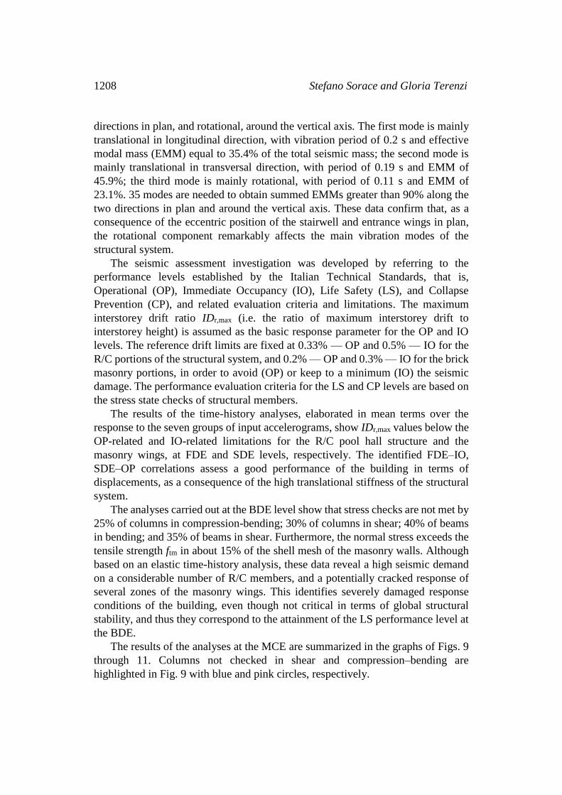
The results of the analyses at the MCE are summarized in the graphs of Figs. 9
through 11. Columns not checked in shear and compression–bending are
highlighted in Fig. 9 with blue and pink circles, respectively.
Analysis and seismic isolation 1209
Fig. 9. Summary of columns in unsafe conditions at the MCE.
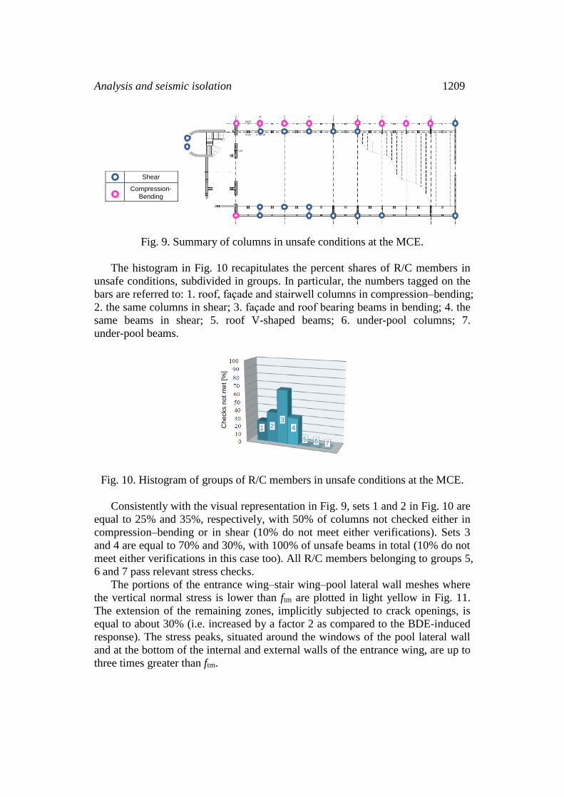
The histogram in Fig. 10 recapitulates the percent shares of R/C members in
unsafe conditions, subdivided in groups. In particular, the numbers tagged on the
bars are referred to: 1. roof, façade and stairwell columns in compression–bending;
2. the same columns in shear; 3. façade and roof bearing beams in bending; 4. the
same beams in shear; 5. roof V-shaped beams; 6. under-pool columns; 7.
under-pool beams.
Fig. 10. Histogram of groups of R/C members in unsafe conditions at the MCE.
Consistently with the visual representation in Fig. 9, sets 1 and 2 in Fig. 10 are
equal to 25% and 35%, respectively, with 50% of columns not checked either in
compression–bending or in shear (10% do not meet either verifications). Sets 3
and 4 are equal to 70% and 30%, with 100% of unsafe beams in total (10% do not
meet either verifications in this case too). All R/C members belonging to groups 5,
6 and 7 pass relevant stress checks.
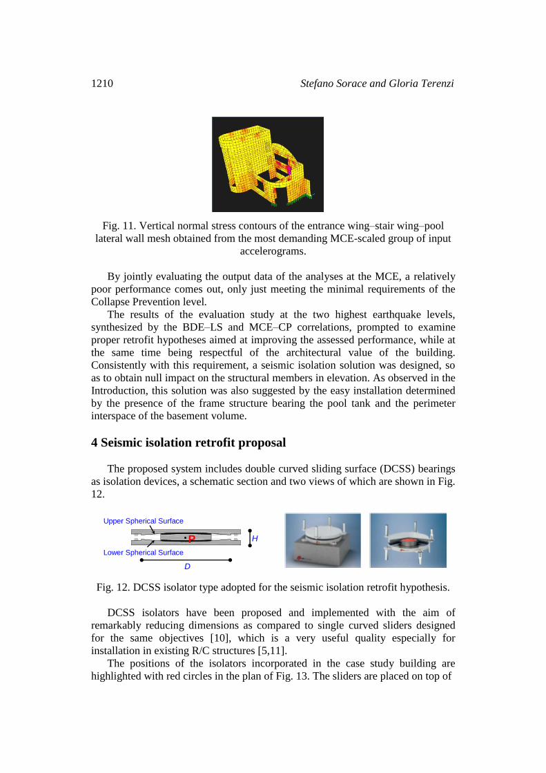
The portions of the entrance wing–stair wing–pool lateral wall meshes where
the vertical normal stress is lower than ftm are plotted in light yellow in Fig. 11.
The extension of the remaining zones, implicitly subjected to crack openings, is
equal to about 30% (i.e. increased by a factor 2 as compared to the BDE-induced
response). The stress peaks, situated around the windows of the pool lateral wall
and at the bottom of the internal and external walls of the entrance wing, are up to
three times greater than ftm.
Shear
Compression-Bending
1 Checks n
ot
met
[%]
2 3
4
5 6 7
1210 Stefano Sorace and Gloria Terenzi
Fig. 11. Vertical normal stress contours of the entrance wing–stair wing–pool
lateral wall mesh obtained from the most demanding MCE-scaled group of input
accelerograms.
By jointly evaluating the output data of the analyses at the MCE, a relatively
poor performance comes out, only just meeting the minimal requirements of the
Collapse Prevention level.
The results of the evaluation study at the two highest earthquake levels,
synthesized by the BDE–LS and MCE–CP correlations, prompted to examine
proper retrofit hypotheses aimed at improving the assessed performance, while at
the same time being respectful of the architectural value of the building.
Consistently with this requirement, a seismic isolation solution was designed, so
as to obtain null impact on the structural members in elevation. As observed in the
Introduction, this solution was also suggested by the easy installation determined
by the presence of the frame structure bearing the pool tank and the perimeter
interspace of the basement volume.
4 Seismic isolation retrofit proposal
The proposed system includes double curved sliding surface (DCSS) bearings
as isolation devices, a schematic section and two views of which are shown in Fig.
12.
Fig. 12. DCSS isolator type adopted for the seismic isolation retrofit hypothesis.
DCSS isolators have been proposed and implemented with the aim of
remarkably reducing dimensions as compared to single curved sliders designed
for the same objectives [10], which is a very useful quality especially for
installation in existing R/C structures [5,11].
The positions of the isolators incorporated in the case study building are
highlighted with red circles in the plan of Fig. 13. The sliders are placed on top of
H
D
Upper Spherical Surface
(R, μ)
Lower Spherical Surface
P

Analysis and seismic isolation 1211
each column of the under-pool structure (60 elements), at the bottom of each pair
of façade columns-roof columns (16 elements), and below the stairwell/entrance
wing walls and the lateral walls of the pool hall (19 elements). This results in a
multi-level geometrical isolation plane, marked by red lines in the longitudinal
cross section drawn in Fig. 13. The plane is constituted by the continuous R/C
slabs of the pool tank and hall, plus the ground story slab of the masonry wings.
The mutual 300 mm thickness of these slabs warrants an effective rigid diaphragm
function of the plane, as required for the best performance of any isolation system.
Fig. 13. Plan with the positions of the DCSS isolators (red circles) and
longitudinal cross section highlighting the geometrical layout of the multilevel
isolation plane.
As a consequence of the relatively small tributary areas to gravitational loads of
the under-pool columns, as well as of the lightweight barrel vault of the hall, the
required axial force-resisting surface of the isolators is provided by the smallest
type of DCSS devices in standard production by the selected manufacturer [12].
The mechanical and geometrical properties of this model are as follows: effective
pendulum length LDFP=2535 mm; maximum displacement capacity dmax=200 mm;
friction coefficient of the sliding surfaces μ=0.025; equivalent vibration period of
the isolator at the maximum displacement Te(dmax)=2.78 s; equivalent viscous
damping ratio at the maximum displacement e(dmax)=15.2%; plan diameter of the
concave surfaces D=400 mm; H=height=84 mm; and maximum dimension in plan
including the connection flanges Dc=450 mm.
The Dc value allows mounting the isolators on top of the under-pool columns
and at the bottom of the façade-roof column pairs (i.e. on top of the underlying
basement wall) without enlarging relevant bearing members. At the same time, a

1212 Stefano Sorace and Gloria Terenzi
500 mm-wide R/C edge beam must be built at the base of the masonry walls
before incorporating the isolators. By way of example, the installation details of a
device below the façade-roof columns are shown in the drawing of Fig. 14,
highlighting that demolitions are limited to a 130 mm-thick top portion of the
basement wall.
Fig. 14. Installation details of an isolator at the bottom of a façade-roof column
pair.
For the development of the time-history analyses in seismically isolated
configuration, the finite element model of the DCSS devices was generated by the
special “Friction Isolator” link element available in the library of SAP2000NL
software. This is a biaxial friction-pendulum element with coupled friction
properties for the deformations along the two reference local axes in plan, and
“gap”-type behaviour in vertical direction.
The first two vibration modes in isolated conditions are essentially translational
along the longitudinal direction (first mode) and the transversal direction (second
mode), with periods of 2.82 s (first) and 2.81 s (second). The two values are very
similar to the equivalent period of the isolators, Te(dmax), as a consequence of the
negligible contribution of the superstructure deformability to these modes. The
modal masses are nearly equal to 100% of the total seismic mass in both directions.
2+2 12
Stirrups 8/200
2+2 12
3+3 14
High-Strength Concrete Mortar – s=30
R/C Perimeter Wall
DCSS isolator
Façade column 250x250
Roof column 250x400–600
Pool Slab – H=300
Demolished portion – t=130

- 160 -120
-80 -40
0 40 80 120
160
- 8
- 6
- 4
- 2
0
2
4
6
8
Displacement [mm]
Fo
rce [kN
]
Pool Hall
Analysis and seismic isolation 1213
The third mode is purely rotational, with period of 2.6 s, and EMM equal to about
100% of the seismic mass too.
The performance evaluation enquiry carried out in original conditions was
duplicated in the base isolation retrofit hypothesis. The good response at the two
lowest earthquake levels assessed in current state is improved further thanks to the
protective intervention, reaching the OP limit state at SDE too, in addition to the
FDE.
Concerning the BDE and MCE levels, all R/C members result to be within
their safe domain, and the normal stress peaks in the masonry walls below ftm, in
isolated conditions. The latter result is visualized in the mesh view of Fig. 15,
where the elements with stress values lower than ftm are plotted in purple.
Fig. 15. Vertical normal stress contours of the entrance wing–stair wing–pool
lateral wall mesh obtained from the most demanding MCE-scaled group of input
accelerograms in isolated conditions.
The peak displacements of the DCSS isolators were checked at the MCE level.
The response cycles obtained from the most demanding group of input
accelerograms for three devices, placed on top of the under-pool columns, at the
bottom of the façade-roof column pairs and at the bottom of the stairwell wing,
respectively, are plotted in Fig. 16.
Fig. 16. Response cycles of three isolators obtained from the most demanding
MCE-scaled group of input accelerograms.
A mutual maximum displacement of about 100 mm is recorded, i.e. half the
isolator capacity dmax=200 mm. The responses of the three devices are practically
coincident and in-phase in terms of displacements, underlining that the retrofitted
Displacement [mm]
-160 -120 -80 -40 0 40 80
120 160
- 8 - 6 - 4 - 2
0 2
4 6 8
Fo
rce [kN
]
Stairwell Wing
Displacement [mm]
-160 -120 -80 -40 0 40 80
120 160
- 8 - 6
- 4 - 2
0 2
4
6 8
Fo
rce [kN
]
Pool Tank
1214 Stefano Sorace and Gloria Terenzi
structure is substantially unaffected by plan torsion effects. The differences in terms
of forces and stiffness are related to the different axial forces acting on the isolators.
The displacement capacity/demand ratio equal to about 2:1 guarantees adequate
safety margins with respect to the physical effects not modelled in the analysis,
among which a decrease in nominal friction coefficient due to the simultaneous
three-directional seismic excitation, and the start of sliding of the two surfaces at
different times, caused by possible unequal sticking.
5 Conclusions
The study carried out on the swimming pool building of the Naval Academy in
Leghorn assesses a relatively satisfactory performance of the structure at the FDE
and SDE, identified by FDE–IO and SDE–OP correlations, as a consequence of its
high elastic translational stiffness.
On the other hand, at the BDE either compression or shear stress checks are not
met by 30% of columns and 40% of beams, and the normal stress exceeds the
tensile strength in about 15% of the masonry wall meshes, outlining the attainment
of the LS performance level.
The increased number of unsafe R/C members and the wider extension of
potentially cracked zones of masonry walls surveyed at the MCE, in comparison to
the BDE, allow meeting only the minimal requirements of the CP limit state.
Based on these data, targeting and reaching a substantial seismic performance
improvement would imply notably intrusive interventions, not respectful of the
architectural value of the building, should traditional rehabilitation techniques be
adopted. Therefore, a seismic isolation retrofit hypothesis was proposed, so as to
generate a null impact on the structural members in elevation.
This solution allows reaching safe response in all R/C members and tensile
stress distributions below relevant strength in all masonry walls, thus identifying
BDE–IO and MCE–IO correlations.
The technical and economic feasibility of the intervention are favoured by the
possibility of easily installing the isolation system, owed to the presence of the
frame structure bearing the pool tank and the perimeter interspace of the basement
volume.
Hopefully, this will help adopt the same strategy for other R/C vaulted
structures built in seismic areas during the “golden-age” decades.
Acknowledgements. The study reported in this paper was financed by the
Italian Department of Civil Protection within the ReLUIS-DPC Project 2016,
Research Line 6: Isolation and Dissipation. The authors gratefully acknowledge
this financial support.
References
[1] S. Sorace and G. Terenzi, Structural assessment of a modern heritage

Analysis and seismic isolation 1215
building, Engineering Structures, 49 (2013), 743-755.
http://dx.doi.org/10.1016/j.engstruct.2012.12.012
[2] A. Custance-Baker and S. Macdonald, Conserving Concrete Heritage, The
Getty Conservation Institute, Los Angeles, CA, 2014.
[3] S. Sorace and G. Terenzi, Dissipative bracing-based seismic retrofit of R/C
school buildings, The Open Construction and Building Technology Journal,
6 (2012), 334-345. http://dx.doi.org/10.2174/1874836801206010334
[4] F. Mazza, Modelling and nonlinear static analysis of reinforced concrete
framed buildings irregular in plan, Engineering Structures, 80 (2014), 98-108.
http://dx.doi.org/10.1016/j.engstruct.2014.08.026
[5] S. Sorace, G. Terenzi and C. Mori, Passive energy dissipation-based retrofit
strategies for R/C frame water towers, Engineering Structures, 106 (2016),
385-398. http://dx.doi.org/10.1016/j.engstruct.2015.10.038
[6] Italian Council of Public Works, Commentary on the Technical Standards on
constructions [in Italian], Rome, Italy, 2009.
[7] Italian Council of Public Works, Technical Standards on Constructions [in
Italian], Rome, Italy, 2008.
[8] E.H. Vanmarcke, G.A. Fenton and E. Heredia-Zavoni, SIMQKE-II-
conditioned earthquake ground motion simulator: User’s manual, version 2.1,
Princeton University, Princeton, New Jersey, 1999.
[9] CSI, SAP2000NL, Structural analysis programs- Theoretical and users
manual, Release no.17.06, Berkeley, California, 2016.
[10] D.M. Fenz and M.C. Constantinou, Behaviour of the double concave friction
pendulum bearing, Earthquake Engineering and Structural Dynamics, 35
(2006), 1403-1424. http://dx.doi.org/10.1002/eqe.589
[11] S. Sorace and G. Terenzi, A viable base isolation strategy for the advanced
seismic retrofit of an R/C building, Contemporary Engineering Sciences, 7
(2014), 817-834. http://dx.doi.org/10.12988/ces.2014.4549
[12] FIP, Anti-seismic devices product division 2016.
http://www.fip-group.it
Received: June 29, 2016; Published: September 17, 2016