analysis and predictionof multi-heating lines … and predictionof multi-heating lines effect on...
TRANSCRIPT

Copyright c© 2008 Tech Science Press CMES, vol.28, no.1, pp.1-14, 2008
Analysis and Prediction of Multi-Heating Lines Effect on Plate Forming byLine Heating
Adan Vega1, Sherif Rashed2, Yoshihiko Tango3, Morinobu Ishiyama3 and Hidekazu Murakawa2
Abstract: Experimental observations haveshown that the inherent deformation producedby multi-heating lines is not a simple additionof the inherent deformation produced by singleheating lines. Therefore, to accurately predictinherent deformation, the method of superposinginherent deformation of single heating lines isnot appropriate. To overcome this difficulty, theauthors investigate the influence of multi-heatinglines on line heating inherent deformation.First, the influence of previous heating lines oninherent deformation of overlapping, parallel andcrossing heating lines is clarified. The influenceof the proximity to plate side edge on inherentdeformation is also taken into account in theanalysis. It is demonstrated that residual stressesproduced by previous heating lines is the mainfactor influencing the inherent deformation ofmulti-heating lines, while the influence of theproximity to plate side edge on multi-heatinglines is small and can be neglected.
Keyword: Line heating, inherent deformation,FEM, multi-heating, residual stresses, side edgeeffect.
1 Introduction
Forming by line heating has been an active re-search topic in manufacturing, especially in ship-building. The problem of forming by line heat-ing can be divided into two sub-problems: theheat transmission problem and the elasto-plasticdeformation problem. The first problem has beenwidely studied and efficient techniques have beenpresented (Moshaiov and Latorre (1985), Tsuji
1 Graduate School of Engineering, Osaka University-Japan2 Joining and Welding Research Institute, Osaka University,
Japan3 IHI Engineering, Marine, Showa, Kure, Japan
and Okumura (1989), Terasaki, Kitamura andNakai (1999), Chang, Liu, and Chang (2005),Ling and Atluri (2006), Liu (2006), Liu, Liu,and Hong (2007), Osawa, Hashimoto, Sawamura,Kikuchi, Deguchi, and Yamaura (2007)). Theelasto-plastic deformation problem has been alsowidely studied. Theoretical researches on themechanism of line heating process aimed to pre-dict the final shape of a metal plate when given theheating conditions and mechanical properties ofthe plate material exists (e.g. Moshaiov and Vorus(1987), Moshaiov and Shin (1991), Jang, Seo andKo (1997), Kyrsanidi, Kermanidis and Pantelakis(1999)).
The finite element method or simplified analysisusing the beam or plate theory is usually applied.The relationships between bending deformation,heating parameters and plate thickness have beendeveloped in empirical models and inherent straindata bases (e.g. Ueda, Murakawa, Rashwan, Oku-moto and Kamic, (1994), Jang and Moon (1998)).
Additional information, such as the influence ofstrain hardening, edge effect, and size effect, hasalso been reported in experimental and numericalinvestigations (Magee, Watkins and Steen (1997),Bao and Yao (2001), Cheng, Yao, Liu, Pratt andFan (2005)). However, most of these investiga-tions have focused on the deformation producedby single heating lines on small plates, no empir-ical method or inherent strain database has beendeveloped for actual size plates.
The authors aim to propose a practical and ac-curate method to predict deformation of actualsize plates such as those used in shipbuilding. Asa fundamental component of this method, a lineheating inherent deformation database is indeednecessary. This inherent deformation databasebesides being mainly dependent on primary fac-
2 Copyright c© 2008 Tech Science Press CMES, vol.28, no.1, pp.1-14, 2008
tors such as the plate thickness, the heat sourcespeed and the heat input, it also takes into ac-count secondary factors such as the geometry ofthe plate, the cooling condition, the location ofthe heating line, multi-heating lines, heat-inducedcurvature, residual stresses and inter-heating tem-perature. Here, it is to be noted that the influ-ences of these secondary factors are not so sim-ple that they can be linearly related to primaryfactors. Also, it is difficult to obtain these influ-ences by experiments because of the large scat-ter in test results. Therefore, to clarify the influ-ence of these secondary factors on inherent de-formation a 3D thermal-elastic-plastic FEM usingan iterative substructure method (ISM) is utilized(Nishikawa, Serizawa and Murakawa (2005)).
In this report, the effect of multi-heating lines oninherent deformation is investigated and clarified.At first, the inherent deformation produced by sin-gle heating lines applied to flat plates is predictedby integrating the inherent strain obtained throughthree dimensional thermal elastic-plastic finite el-ement analyses. Then, a combination of multi-heating lines is applied and the resulting com-puted inherent deformation is compared with thatobtained by superposing the inherent deformationof single heating lines. Three cases (overlapped,parallel and crossed heating lines) are considered.For each case the influence of previous heatinglines on the inherent deformation of current heat-ing line is investigated. The influence of theplate side edge on inherent deformation of multi-heating lines is also investigated. Finally, throughthe analysis of the results, conclusions of the in-fluence of multi-heating lines on inherent defor-mation of plates undergoing line heating are pre-sented.
2 Prediction of line heating inherent defor-mation using 3D thermal elastic-plasticFEM
2.1 Inherent strain due to the line heating
When a continuous body is subjected to a non-uniform heat cycle that produces permanent de-formation, the strain in the deformed body haselastic and plastic components. The total strain
is the summation of these components.
ε = εe +ε p (1)
The elastic components correspond to the residualstresses, and the plastic components are referredto as the inherent strain. It is to be noted that al-though the total strain is compatible in the body,the inherent strain (plastic strain caused by heat-ing and subsequent cooling) is not compatible.
2.2 Method of analysis
Thermal-elastic-plastic FEM is a powerful toolfor predicting line heating inherent deforma-tion. However, three-dimensional thermal-elastic-plastic FE analysis requires very long computa-tion time and large memory. To overcome thisproblem, an in-house three dimensional thermalelastic-plastic finite element code based on aniterative substructure method (Nishikawa, Ser-izawa and Murakawa (2005)) is employed in thisresearch. The iterative substructure method (ISM)takes full advantage of the fact that the regionwhich exhibits strong nonlinearity is limited to avery small area compared to the whole model tobe analyzed, and the remaining part is mostly lin-ear. In this way a large saving of computer time isachieved.
2.2.1 Analysis Procedure
The thermo-mechanical behavior of plate formingby line heating is analyzed using uncoupled for-mulation. However, the uncoupled formulationconsiders the contribution of the transient tem-perature field to stresses through thermal expan-sion, as well as temperature-dependent thermo-physical and mechanical properties. The solu-tion procedure consists of two steps. First, thetemperature distribution history is computed us-ing transient heat transfer analysis. Second, thetransient temperature distributionhistory obtainedfrom the heat transfer analysis is employed as athermal load in a subsequent mechanical analysis.Stresses, strains and displacements are then eval-uated. The same finite element model used in thethermal analysis is employed in mechanical anal-ysis.
Analysis and Prediction of Multi-Heating Lines Effect on Plate Forming by Line Heating 3
2.2.2 Analyzed model
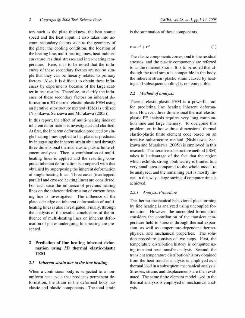
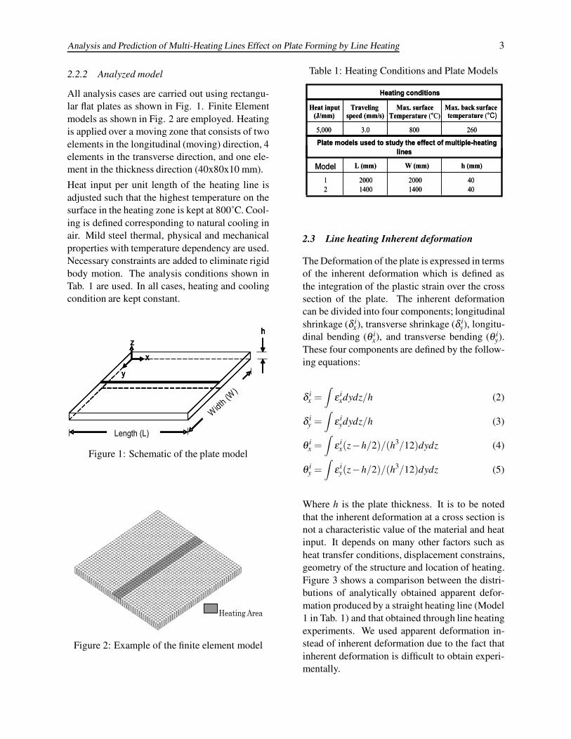
All analysis cases are carried out using rectangu-lar flat plates as shown in Fig. 1. Finite Elementmodels as shown in Fig. 2 are employed. Heatingis applied over a moving zone that consists of twoelements in the longitudinal (moving) direction, 4elements in the transverse direction, and one ele-ment in the thickness direction (40x80x10 mm).
Heat input per unit length of the heating line isadjusted such that the highest temperature on thesurface in the heating zone is kept at 800˚C. Cool-ing is defined corresponding to natural cooling inair. Mild steel thermal, physical and mechanicalproperties with temperature dependency are used.Necessary constraints are added to eliminate rigidbody motion. The analysis conditions shown inTab. 1 are used. In all cases, heating and coolingcondition are kept constant.
Length (L)
Width(W
)
x
y
zh
Length (L)
Width(W
)
x
y
zh
Length (L)
Width(W
)
x
y
zh
Length (L)
Width(W
)
x
y
zh
Figure 1: Schematic of the plate model
Heating Area
Figure 2: Example of the finite element model
Table 1: Heating Conditions and Plate Models
Heating conditions
2608003.05,000
Max. back surface temperature (°C)
Max. surface Traveling speed (mm/s)
Heat input (J/mm)
Plate models used to study the effect of multiple-heating lines
4040
20001400
20001400
12
h (mm)W (mm)L (mm)Model
Temperature (°C)
Heating conditions
2608003.05,000
Max. back surface temperature (°C)
Max. surface Traveling speed (mm/s)
Heat input (J/mm)
Plate models used to study the effect of multiple-heating lines
4040
20001400
20001400
12
h (mm)W (mm)L (mm)Model
Temperature (°C)
2.3 Line heating Inherent deformation
The Deformation of the plate is expressed in termsof the inherent deformation which is defined asthe integration of the plastic strain over the crosssection of the plate. The inherent deformationcan be divided into four components; longitudinalshrinkage (δ i
x), transverse shrinkage (δ iy), longitu-
dinal bending (θ ix), and transverse bending (θ i
y).These four components are defined by the follow-ing equations:
δ ix =
∫ε i
xdydz/h (2)
δ iy =
∫ε i
ydydz/h (3)
θ ix =
∫ε i
x(z−h/2)/(h3/12)dydz (4)
θ iy =
∫ε i
y(z−h/2)/(h3/12)dydz (5)
Where h is the plate thickness. It is to be notedthat the inherent deformation at a cross section isnot a characteristic value of the material and heatinput. It depends on many other factors such asheat transfer conditions, displacement constrains,geometry of the structure and location of heating.Figure 3 shows a comparison between the distri-butions of analytically obtained apparent defor-mation produced by a straight heating line (Model1 in Tab. 1) and that obtained through line heatingexperiments. We used apparent deformation in-stead of inherent deformation due to the fact thatinherent deformation is difficult to obtain experi-mentally.

4 Copyright c© 2008 Tech Science Press CMES, vol.28, no.1, pp.1-14, 2008
0 200 400 600 800 1000 1200 1400 1600 1800 20000
0.1
0.2
0.3
0.4
0.5
0.6
ComputationExperiment
Plate Length (mm)
δyy
(mm
)
(a)
0 200 400 600 800 1000 1200 1400 1600 1800 20000
0.1
0.2
0.3
0.4
0.5
0.6
0.7
ComputationExperimentθy
y (m
m)
Plate Length (mm)(c)
0 200 400 600 800 100012001400160018002000-0.012
-0.009
-0.006
-0.003
0
0.003
0.006
0.009
0.012
ComputationExperiment
δ xx
(mm
)
Plate Length (mm)(b)
0 200 400 600 800 100012001400160018002000-0.012
-0.009
-0.006
-0.003
0
0.003
0.006
0.009
0.012
ComputationExperiment
θxx
(mm
)
Plate Length (mm)
(d)Figure 3: Distribution of the apparent deformation produced by a single heating line (a) Transverse shrink-age, (b) Longitudinal shrinkage, (c) Transverse bending, and (d) Longitudinal bending
Table 2: Influential factors on inherent deformation
Plate Geometry- Plate Length- Plate Width
- Plate Thickness
Heating Condition- Heat Input
- Torch Speed- Torch Size
Cooling Condition- Air Cooling
- Water Cooling- Inter-heat Temperature
Location of the Heating- Entrance Plate Edge- Exit Plate Edge- Side Plate Edge
Multi-heating Lines- Overlapped
- Parallel- Crossed
- Residual Stress- Initial Curvature
- Material properties
OthersPlate Geometry- Plate Length- Plate Width
- Plate Thickness
Heating Condition- Heat Input
- Torch Speed- Torch Size
Cooling Condition- Air Cooling
- Water Cooling- Inter-heat Temperature
Location of the Heating- Entrance Plate Edge- Exit Plate Edge- Side Plate Edge
Multi-heating Lines- Overlapped
- Parallel- Crossed
- Residual Stress- Initial Curvature
- Material properties
Others
3 Problem description and overall strategy
The plate forming process by line heating can beviewed as a process to form a plate into a de-sired shape using the shrinkage and angular dis-tortion produced through the plastic deformationproduced during line heating. To form plates withgeneral three-dimensional geometry which makemost of the curved parts of ship structures, it maybe necessary to properly combine in-plane shrink-age and angular deformation according to eachparticular situation.
Values of in-plane shrinkage and angular distor-tion produced by line heating can be accuratelyobtained based on the geometry and the heatingcondition if the secondary factors affecting the de-formation are taken into account.
Ueda, Murakawa, Rashwan, Okumoto andKamichika (1993), proposed an automatic platebending process which has been successfully usedin ship plates forming. This process consists offour steps which can be summarized as follow.The first step is to determine, using FEM, the nec-
Analysis and Prediction of Multi-Heating Lines Effect on Plate Forming by Line Heating 5
essary inherent strain to form the plate from itsinitial shape to the desired shape. The secondstep is to determine the positions and directionsof the heating lines, the kind of inherent defor-mation (inplane shrinkage/or angular distortion)and its magnitude. The third step is to determinethe heating and cooling condition to produce thenecessary inherent deformation from inherent de-formation databases which is to be established byline heating analysis using FEM. The last step isto determine the condition to correct the geometri-cal error left after forming based on the first, sec-ond and third steps. However, to fully automatethis process and minimize the work in the fourthstep, accuracy improvements are necessary.
As an overall strategy to improve the accuracy ofthe forming process, the authors pay attention tothose factors which may influence line heating in-herent deformation. In order to identify impor-tant factors influencing inherent deformation, firstwe analyze the inherent deformation produced bysingle heating lines and compare it with that ob-tained by different combination of multi- heatinglines. It is found that many factors influence theinherent deformation. A summary of these factorsis presented in Tab. 2. In previous reports, the in-fluence of the plate geometry and the edge effecton inherent deformation are studied and clarified(Vega, Rashed, Serizawa and Murakawa (Report1, 2007), Vega, Tajima, Rashed and Murakawa(Report 2, 2007)). In this report we aim to clar-ify the influence of multi-heating lines on inher-ent deformation. Further reports will be presentedaiming to propose a practical and accurate methodto predict inherent deformation, and hence theformed shape of a plate.
4 Influence of multi-heating lines on inherentdeformation
In forming 3-D shapes, ship curved plates for ex-ample, complicated heating patterns are needed.Combinations of heating lines in different direc-tion are applied to finally get the plastic strain nec-essary to form the plate. On the other hand, whentwo heating lines are applied close to each other, itis observed that the resulting inherent deformationis not a simple addition of that produced by each
heating line applied alone to a stress-free plate.
With the aim to clarify this difference, we baseour discussion on the influence of previous heat-ing lines on inherent deformation produced by acurrent heating line. This influence is mainly dueto the fact that when the previous heating linecools down to room temperature, inherent defor-mation and residual stresses are produced. Both,the inherent deformation and the residual stressesinfluence each other. If the current heating line isapplied over an area in which compressive resid-ual stresses exist, additional compressive plasticstrain will be produced in the heating process,therefore, at the end, the inherent deformation islarger than that produced by the previous heatingline. In the same way, if the current heating lineis applied over an area in which tensile residualstresses exist, additional tensile plastic strain isproduced in the heating process. Then, after theplate cools down to room temperature, the inher-ent deformation is smaller than that of the previ-ous heating line.
Width (W)
Width (W)
x
z
y
12
3
4 5 6 Width (W)
Width (W)
x
z
y
12
3
4 5 6 Width (W)
Width (W)
x
z
y
12
3
4 5 6 Width (W)
Width (W)
x
z
y
12
3
4 5 6
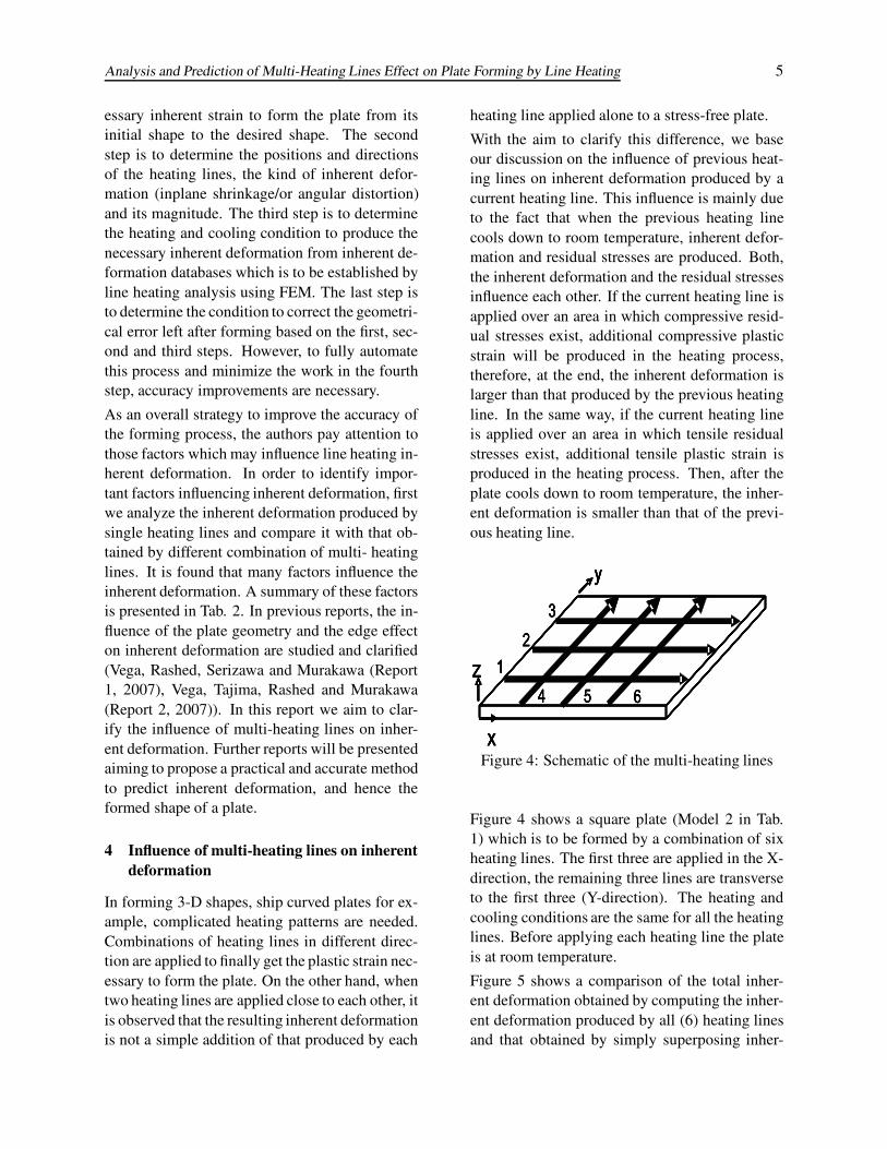
Figure 4: Schematic of the multi-heating lines
Figure 4 shows a square plate (Model 2 in Tab.1) which is to be formed by a combination of sixheating lines. The first three are applied in the X-direction, the remaining three lines are transverseto the first three (Y-direction). The heating andcooling conditions are the same for all the heatinglines. Before applying each heating line the plateis at room temperature.
Figure 5 shows a comparison of the total inher-ent deformation obtained by computing the inher-ent deformation produced by all (6) heating linesand that obtained by simply superposing inher-
6 Copyright c© 2008 Tech Science Press CMES, vol.28, no.1, pp.1-14, 2008
ent deformation of each single heating line whenapplied alone to the stress-free plate. By simpleinspection it may be seen that the difference be-tween results, especially in the longitudinal com-ponents of inherent deformation is large.
To better understand this influence, we considerthree combinations of heating lines actually usedin plate forming by line heating. At first, we ex-amine the influence of a previous heating line onthe inherent deformation of an overlapping heat-ing line (for example heating 1 + 1 in Fig. 4).Then, we examine the case of parallel heatinglines (for example heating 1 + 2 in Fig. 4) andthe case of heating lines which cross each other(for example heating 1 + 4 in Fig. 4). The influ-ence of side plate edges is investigated in the caseof parallel heating lines. The influence of multi-crossed heating lines on inherent deformation isalso studied and clarified.
4.1 Overlapped heating lines
The process of forming inherent deformation byoverlapped heating lines has been explained us-ing a simplified three bars mechanical model (seeVega, Tajima, Rashed and Murakawa (2007)). Toillustrate that, let us suppose that a straight heat-ing line is applied along the plate length (Model1 in Tab. 1). After the heated area cools down toroom temperature, a second overlapping heatingline with the same heating and cooling conditionas the first, is applied.
Figure 6 shows the average residual stresses (av-erage over the thickness) σxx and σyy produced bythe first heating line plotted along (a) and trans-verse to (b) the heating line. As it may be seenin Fig. 6 (a), large compressive residual stressσyy in Y-direction appear at the entrance and exitedges of the plate. While at both, entrance andexit edges of the plate, the residual stress σxx inX-direction is small. At the middle region ofthe plate, small amount of tensile residual stressσyy in Y-direction exists while the tensile resid-ual stress σxx in X-direction is large. Figure 7compares the computed results of inherent de-formation produced by the first heating line andthat produced by the two overlapped heating lines.From this figure it may be seen that the total in-
herent deformation produced by two overlappedheating lines is not a simple addition of inherentdeformation produced by single heating lines. Toclarify the cause of this variation we study the in-fluence of the residual stresses produced by theprevious heating line (Fig. 6) on the inherent de-formation of the second (overlapping) heating line(Fig. 7).
As mentioned above, when a heating line is ap-plied over an area in which compressive resid-ual stresses exist, at high temperature, additionalcompressive strain is produced, consequently, ad-ditional inherent deformation is created. This in-crement on inherent deformation is clearly ob-served for example, in the transverse componentsof inherent deformation at both edges of the plate(Fig. 7 (a) and (c)). At the central region ofthe plate, small amount of tensile residual stressσyy in Y-direction exists. This tensile residualstress slightly influences the transverse compo-nents of inherent deformation produced by thesecond heating line as shown in Fig. 7 (a) and(c). On the other hand, at the central region ofthe plate, large tensile residual stress σxx in X-direction is observed (Fig. 6). When a second(overlapping) heating line is applied, at high tem-perature, this tensile residual stress is transformedin tensile strain. Due to the fact that the tensilestress is large (close to the yield stress), the ten-sile strain is also large, therefore, the longitudi-nal plastic strain produced by the previous heatingline, almost completely disappears. Then, whenthe plate cools down to room temperature, newcompressive strain is created. This new compres-sive strain produces almost the same inherent de-formation and residual stresses σxx in X-directionas the first heating line. If additional overlappedheating lines are applied, the same phenomenonoccurs, therefore, the longitudinal components ofinherent deformation at the central region of theplate, is almost the same as that obtained by theprevious overlapped heating lines. At both, en-trance and exit edges of the plate, the residualstress σxx in X-direction is small, therefore, nosignificant variation on the longitudinal compo-nents of inherent deformation is observed.

Analysis and Prediction of Multi-Heating Lines Effect on Plate Forming by Line Heating 7
0 200 400 600 800 1000 1200 1400-2
-1.5
-1
-0.5
0
0.5
1Addition of Inherent DeformationComputing Result
Plate Length (mm)
δ yy
(mm
)
(a)
0 200 400 600 800 1000 1200 1400-0.1
-0.050
0.050.1
0.150.2
0.250.3
0.350.4
Addition of Inherent DeformationComputing Result
Plate Length (mm)
θ yy
(rad
)
(c)
0 200 400 600 800 1000 1200 1400-3.5
-3
-2.5
-2
-1.5
-1
-0.5
0
0.5Addition of Inherent DeformationComputing Result
Plate Length (mm)
δ xx
(mm
)
(b)
0 200 400 600 800 1000 1200 1400-0.2
-0.1
0
0.1
0.2
0.3
0.4
0.5
0.6
Addition of Inherent DeformationComputing Result
Plate Length (mm)
θ xx
(rad
)
(d) Figure 5: Comparison of the inherent deformation obtained by computing the line heating pattern shown inFig. 4 and that obtained by superposing inherent deformation of single heating lines. (a) Transverse inherentShrinkage, (b) Longitudinal inherent Shrinkage, (c) Transverse inherent bending, (d) Longitudinal inherentbending
Plate Length (mm)
σ x,y (M
Pa)
0 200 400 600 800 1000 1200 1400 1600 1800 2000-300
-200
-100
0
100
200
300
X-directionY-direction
(a)
Plate Width (mm)
σ x,y (M
Pa)
0 200 400 600 800 1000 1200 1400 1600 1800 2000-50
0
50
100
150
200
250
300
X-directionY-direction
(b)
Figure 6: Residual Stresses Distribution, (a) Along the Heating Line, (b) Transverse to the Heating Line
8 Copyright c© 2008 Tech Science Press CMES, vol.28, no.1, pp.1-14, 2008
0 200 400 600 800 1000 1200 1400 1600 1800 2000-0.4
-0.32
-0.24
-0.16
-0.08
0
0.08
0.16
0.24 Single HeatingOverlapped Heating
Plate Length (mm)
δ yy
(mm
)
(a)
0 200 400 600 800 1000 1200 1400 1600 1800 2000-0.05-0.04-0.03-0.02-0.01
00.010.020.030.040.05
Single HeatingOverlapped Heating
Plate Length (mm)
θ yy
(rad
)
(c)
0 200 400 600 800 1000 1200 1400 1600 1800 2000-0.16
-0.12
-0.08
-0.04
0
0.04
0.08
0.12
0.16Single HeatingOverlapped Heating
Plate Length (mm)
δ xx
(mm
)
(b)
0 200 400 600 800 1000 1200 1400 1600 1800 2000-0.02
-0.015
-0.01
-0.005
0
0.005
0.01
0.015
0.02
Single HeatingOverlapped Heating
Plate Length (mm)
θ xx
(rad
)
(d)
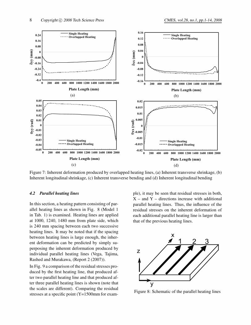
Figure 7: Inherent deformation produced by overlapped heating lines, (a) Inherent transverse shrinkage, (b)Inherent longitudinal shrinkage, (c) Inherent transverse bending and (d) Inherent longitudinal bending
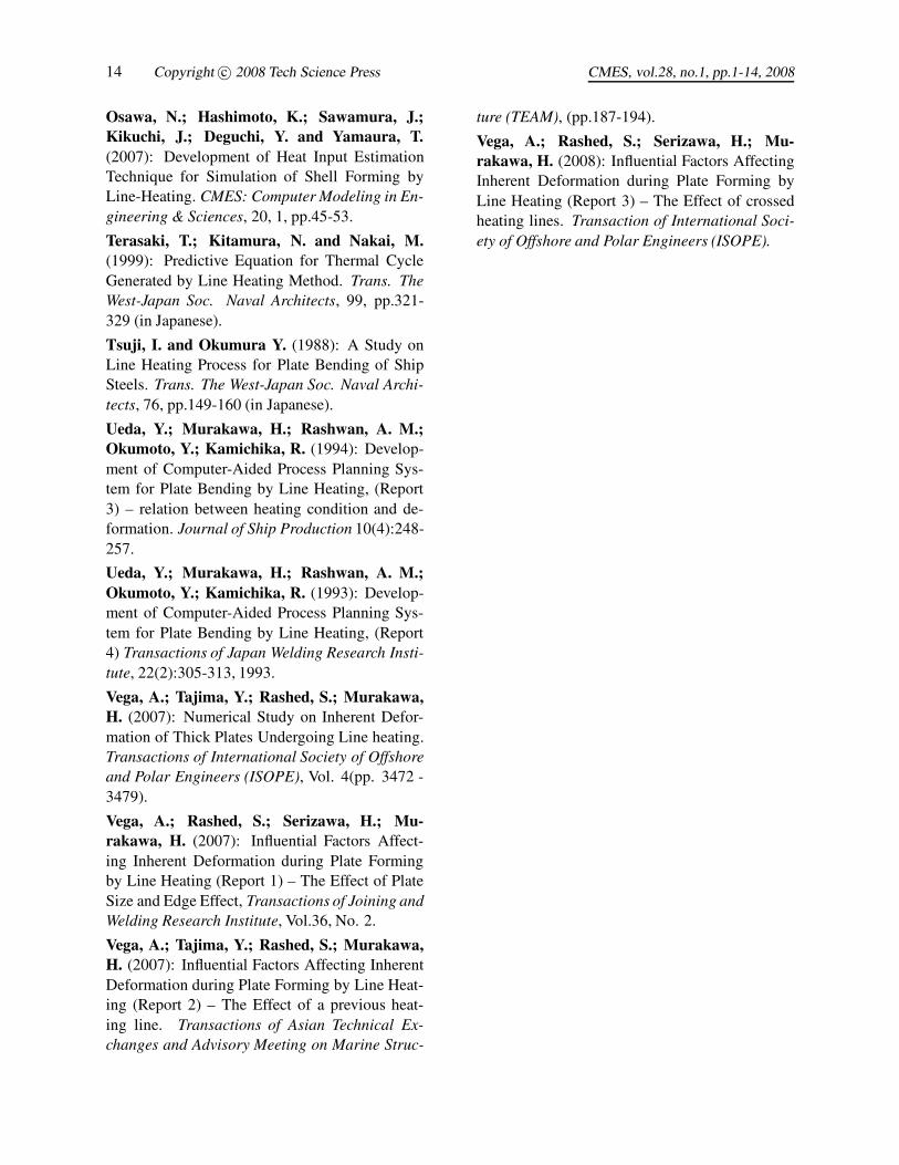
4.2 Parallel heating lines
In this section, a heating pattern consisting of par-allel heating lines as shown in Fig. 8 (Model 1in Tab. 1) is examined. Heating lines are appliedat 1000, 1240, 1480 mm from plate side, whichis 240 mm spacing between each two successiveheating lines. It may be noted that if the spacingbetween heating lines is large enough, the inher-ent deformation can be predicted by simply su-perposing the inherent deformation produced byindividual parallel heating lines (Vega, Tajima,Rashed and Murakawa, (Report 2 (2007)).
In Fig. 9 a comparison of the residual stresses pro-duced by the first heating line, that produced af-ter two parallel heating line and that produced af-ter three parallel heating lines is shown (note thatthe scales are different). Comparing the residualstresses at a specific point (Y=1500mm for exam-
ple), it may be seen that residual stresses in both,X – and Y – directions increase with additionalparallel heating lines. Thus, the influence of theresidual stresses on the inherent deformation ofeach additional parallel heating line is larger thanthat of the previous heating lines.
y
z1 2 3
x
Figure 8: Schematic of the parallel heating lines

Analysis and Prediction of Multi-Heating Lines Effect on Plate Forming by Line Heating 9
Figure 10 shows a comparison between the com-puted inherent deformation produced by a singleheating line, that produced by two parallel heatinglines, and that produced by three parallel heatinglines, respectively. In Figures 10(a) and (c) it isobserved that the transverse components of inher-ent deformation produced by two parallel heatinglines are reduced by the tensile residual stress ex-isting in the area in which the second heating lineis applied (see Fig. 9 (b)). The same effect may beobserved when three parallel heating lines are ap-plied. However, in this case, the reduction of thetransverse components of inherent deformation islarger due to the larger level of residual stresses(it increases with the number of parallel heatinglines). In the same way the compressive residualstresses existing in the area in which the paral-lel heating lines are applied (Fig. 9(a)) cause thelongitudinal components of inherent deformationto increase as shown Fig. 10 (b) and (d). Thisincrease of the inherent deformation also dependson the level of residual stresses and increases withthe number of parallel heating lines.
4.2.1 Influence of plate side edge on parallelheating lines
At first, inherent deformation of single heatinglines applied at different distances from the freeedge (100, 220, 340, 460, 580 and 700 mm) iscomputed. Figure 11 shows the results of theinherent deformation produced at the center ofthe plate by each single heating line. It may beclearly seen that both, transverse and longitudi-nal component of inherent deformation decreaseas the heating line becomes closer to the free edge.However, for those cases which are spaced morethan 400mm from the free edge (for a 40 mm thickplate), the inherent deformation does not signifi-cantly change. From these results, it may be con-cluded that despite the fact that the inherent defor-mation decreases when the heating line becomescloser to side edges, this is not an influential fac-tor in the case of multi-heating lines examined inthis report.
4.3 Crossed heating lines
In this section we examine the inherent defor-mation caused by heating lines which cross eachother. At first, the case of two crossed heatinglines is examined. Figure 12 (a) shows the heat-ing pattern (Model 2 in Tab. 1) used in this anal-ysis. The second heating line (crossing heating)is applied after the first heating area cools downto room temperature. After computing the inher-ent deformation produced by the two heating linesand comparing it with that obtained by superpos-ing inherent deformation produced by two sin-gle heating lines, it is observed that the resultinginherent deformation is significantly influencedespecially at the crossing area. The difference,which is also caused by the residual stresses pro-duced by the previous heating line, is defined bythe authors as the cross effect (see Vega, Rashed,Serizawa and Murakawa (Report 3, 2008)).
To better understand the cross effect, let us ana-lyze the residual stress distribution produced by astraight heating line shown in Fig. 6. Now, if atransverse heating line (heating 2 in Fig. 12 (a)) isapplied over the residual stress pattern shown inFig. 6, and when the area in which both heatinglines intersect is at high temperature, the residualtensile stress is transformed into additional ten-sile strain, as explain before. Due to the fact thatthis tensile strain is large, the longitudinal com-ponent of inherent deformation produced by theprevious heating line at the crossed area is al-most completely released. Then, when the platecools down, new compressive strain is producedalong the second heating line. This new compres-sive strain is also affected by the residual stressesfar from the crossing area. Figure 13 shows thedistribution of the cross effect along the secondheating line (heating 2 in Fig. 12 (a)). Here, thecross effect (Δδx, Δδy, Δθx and Δθy) is defined asthe difference between the inherent deformationobtained by superposing inherent deformation ofsingle heating lines and that obtained from com-puting the two crossed heating lines.
Despite the fact that at the crossing area, ten-sile residual stresses in X and Y direction exist,the cross effect on inherent transverse shrinkage,for example, is positive (decreases the inherent

10 Copyright c© 2008 Tech Science Press CMES, vol.28, no.1, pp.1-14, 2008
Plate Width (mm)
σ xx (
MPa
)
0 200 400 600 800 1000 1200 1400 1600 1800 2000-100
-50
0
50
100
150
200
250
300
Single HeatingTwo Parallel HeatingThree Parallel Heating
(a) Plate Width (mm)
σ yy (
MPa
)
0 200 400 600 800 1000 1200 1400 1600 1800 20000
5
10
15
20
25
30
Single HeatingTwo Parallel HeatingThree Parallel Heating
(b)
Figure 9: Residual Stresses Distribution (transverse to the heating line, at L/2), a) stress in X-direction, b)Stress in Y-direction
Plate Length (mm)
δ yy
(mm
)
0 200 400 600 800 1000 1200 1400 1600 1800 2000-0.5
-0.4
-0.3
-0.2
-0.1
0
0.1
0.2
0.3
0.4
Single HeatingTwo Parallel HeatingThree Parallel Heating
(a)
Plate Length (mm)
θ yy
(rad
)
0 200 400 600 800 1000 1200 1400 1600 1800 2000-0.06
-0.04
-0.02
0
0.02
0.04
0.06
0.08
Single HeatingTwo Parallel HeatingThree Parallel Heating
(c)
Plate Length (mm)
δ xx
(mm
)
0 200 400 600 800 1000 1200 1400 1600 1800 2000-0.35
-0.3
-0.25
-0.2
-0.15
-0.1
-0.05
0
0.05
0.1
0.15
Single HeatingTwo Parallel HeatingThree Parallel Heating
(b)
Plate Length (mm)
θ xx
(rad
)
0 200 400 600 800 1000 1200 1400 1600 1800 2000-0.02
-0.01
0
0.01
0.02
0.03
0.04
0.05
Single HeatingTwo Parallel HeatingThree Parallel Heating
(d)Figure 10: Inherent deformation produced by parallel heating lines; (a) Inherent transverse shrinkage, (b)Inherent longitudinal shrinkage, (c) Inherent transverse bending, (d) Inherent longitudinal bending

Analysis and Prediction of Multi-Heating Lines Effect on Plate Forming by Line Heating 11
Distance from the Plate Side Edge (mm)
δ x,y
(mm
)
100 220 340 460 580 700-0.2
-0.175
-0.15
-0.125
-0.1
-0.075
-0.05
-0.025
0
Longitudinal ShrinkageTransverse Shrinkage
(a)Distance from the Plate Side Edge (mm)
θ x,y
(mm
)
100 220 340 460 580 7000
0.0030.0060.0090.0120.0150.0180.0210.0240.0270.03
Longitudinal BendingTransverse Bending
(b)
Figure 11: Influence of the plate side edge on inherent deformation of parallel heating lines (a) Inherentshrinkage, (b) Inherent bending
transverse shrinkage) while on inherent longitu-dinal shrinkage is negative (increases the inher-ent shrinkage). It is due to the fact that the com-ponent of residual stress in X-direction is muchlarger than that in Y-direction (see Fig. 6). Thetensile X-direction residual stresses have a largeeffect while the Y-direction residual stress doesnot have a significant effect. The increment of in-herent deformation in the longitudinal direction isdue to the incompressibility of the plastic defor-mation of the material.
4.3.1 Influence of multi-crossed heating lines oninherent deformation
Here we examine the case in which after applyingthe heating lines 1 to 6 shown in Fig. 12 (b), acrossing heating line (heating line 7 in the samefigure) is applied. Figure 14 shows a comparisonof the resulting cross effect and that of the influ-ence of parallel heating lines. To construct thisfigure, at first we compute the influence of par-allel heating lines (heating 1 to 6 in Fig. 12 (b))then we compute the influence of multi-crossedheating lines (heating 1 to 7 in the same figure).
The difference between both results is the crosseffect. It is to be noted that the cross effect in thiscase is smaller than that produced in the case ofsingle crossed heating lines. This is due to thefact that after applying additional parallel heat-ing lines, the tensile residual stresses produced byprevious heating lines is reduced as shown Fig. 9
(a) (b)
y
x1 3 5
2 4 6
7
y
x1 3 5
2 4 6
7
x1 3 5
2 4 6
7
x1
2
y y
x1 3 5
2 4 6
7
x1 3 5
2 4 6
7
y
x1 3 5
2 4 6
7
x1 3 5
2 4 6
7
x1
2
y
x1
2
y
Figure 12: Schematic of crossed heating lines(a) Single crossed heating lines, (b) Multi-crossedheating lines
(a). In Fig. 14 it is clearly seen that the influenceof crossed heating lines on inherent deformationis small and it is concentrated at each crossed area,except at the last crossed area (where the residualstress is not reduced) while the influence of par-allel heating lines is distributed along the heatingline and it increases with the number of heatinglines.
5 Conclusions
Through a 3D thermal elastic-plastic finite ele-ment analysis the inherent deformation of multi-heating lines is examined and clarified. From theresults of this investigation, the following conclu-sions are drawn.
The inherent deformation of multi-heating linesis not a simple addition of inherent deformationof individual heating lines. Consequently, the

12 Copyright c© 2008 Tech Science Press CMES, vol.28, no.1, pp.1-14, 2008
Plate Length (mm)
Δδx,
y (m
m)
0 200 400 600 800 1000 1200 1400-0.3
-0.2
-0.1
0
0.1
0.2
0.3
0.4
0.5Transverse ShrinkageLongitudinal Shrinkage
(a)
Plate Length (mm)
Δθx,
y (rad
)
0 200 400 600 800 1000 1200 1400-0.08
-0.06
-0.04
-0.02
0
0.02
0.04
Transverse BendingLongitudinal Bending
(b)
Figure 13: The cross effect (a) Effect on inherent shrinkage, (b) Effect on inherent bending
Plate Length (mm)
Δδyy
(mm
)
0 200 400 600 800 1000 1200 1400-0.9
-0.75-0.6
-0.45-0.3
-0.150
0.150.3
0.450.6
0.75
Effect of Parallel HeatingEffect of Crossed Heating
(a)
Plate Length (mm)
Δθyy
(rad
)
0 200 400 600 800 1000 1200 1400-0.15-0.12-0.09-0.06-0.03
00.030.060.090.120.15
Effect of Parallel HeatingEffect of Crossed Heating
(c)
Plate Length (mm)
Δδxx
(mm
)
0 200 400 600 800 1000 1200 1400-0.6
-0.4
-0.2
0
0.2
0.4
0.6
0.8
1
1.2
Effect of Parallel HeatingEffect of Crossed Heating
(b)
Plate Length (mm)
Δθxx
(rad
)
0 200 400 600 800 1000 1200 1400-0.2
-0.16
-0.12
-0.08
-0.04
0
0.04
0.08
0.12
Effect of Parallel HeatingEffect of Crossed Heating
(d)
Figure 14: Influence of multi-crossed heating lines on inherent deformation (a) Inherent transverse shrink-age, (b) Inherent longitudinal shrinkage, (c) Inherent transverse bending, and (d) Inherent longitudinal bend-ing

Analysis and Prediction of Multi-Heating Lines Effect on Plate Forming by Line Heating 13
method of superposing inherent deformation ofsingle heating lines does not accurately predict in-herent deformation.
The influences of multi-heating lines on inherentdeformation is mainly due to the effect of resid-ual stresses produced by previous heating lines oninherent deformation caused by following heatinglines.
The effect of a previous heating line on the inher-ent deformation of a following heating line varieswith the separation between the two heating lines.Three combinations of multi-heating lines need tobe considered (overlapped, parallel and crossedheating lines).
The influence of the plate side edge on inherentdeformation is appreciable only close to the sideand its effect on inherent deformation of multi-heating lines is expected to be small.
Acknowledgement: Financial support fromNew Energy and Industrial Technology Devel-opment Organization (NEDO) through the JapanSpace Utilization Promotion Center (JSUP) in theprogram of Ministry of Economy, Trade and In-dustry is gratefully acknowledged.
References
Bao, J.; Yao, Y. L. (2001): Analysis and Predic-tion of Edge Effects in Laser Bending. Journal ofManufacturing Science and Engineering, ASMEVol. 123:53-61.
Chang, C.W.; Liu, C.S. and Chang, J.R.(2005): A Group Preserving Scheme for In-verse Heat Conduction Problems. CMES: Com-puter Modeling in Engineering & Sciences, 10, 1,pp.13-38.
Cheng, P.; Yao, Y. L.; Liu, C.; Pratt, D.; Fan, Y.(2005): Analysis and Prediction of Size Effect onLaser Forming of Sheet Metal. Journal of Manu-facturing Process, SME Vol. 7/No.1; 28-40.
Jang, C. D.; Seo, S.; Ko. D. E. (1997): Astudy on the prediction of deformations of platesdue to line heating using a simplified thermalelasto-plastic analysis. Journal of Ship Produc-tion, 13(1):22-27.
Jang, C. D.; Moon, S. C. (1998): An Algorithmto Determine Heating Lines for Plate Forming byLine Heating Method. Journal of Ship Produc-tion, 14(4):238-245.
Kyrsanidi, A. K.; Kermanidis, T. B.; Pante-lakis S. G. (1999): Numerical and experimentalinvestigation of the laser forming process. Jour-nal of Materials Processing Technology, 87:281-290.
Ling, X. and Atluri, S.N. (2006): StabilityAnalysis for Inverse Heat Conduction Problems.CMES: Computer Modeling in Engineering &Sciences, 13, 3, pp.219-228.
Liu, C.S. (2006): An Efficient Simultaneous Esti-mation of Temperature-Dependent Thermophysi-cal Properties. CMES: Computer Modeling in En-gineering & Sciences, 14, 2, pp.77-90.
Liu, C.S.; Liu L.W. and Hong, H.K. (2007):Highly Accurate Computation of Spatial-Dependent Heat Conductivity and Heat Capacityin Inverse Thermal Problem. CMES: ComputerModeling in Engineering & Sciences, 17, 1,pp.1-18.
Magee, J.; Watkins, K. G.; Steen, W. M.;Calder, N.; Sidhu J.; Kirby, J. (1997):“Edge ef-fect in laser forming,” Laser assisted net shape en-gineering 2, Proceeding of the LANE’97, Meisen-bach Bamberg, pp.399-408.
Moshaiov, A. and Latorre, R. (1985): Temper-ature Distribution during Plate Bending by TorchFlame Heating. Journal of Ship Research, 29, 1,pp.1-11.
Moshaiov A.; Shin, J. G. (1991): Modified stripmodel for analyzing the line heating method-part2: Thermo-elastic-plastic plates. Journal of ShipResearch, 35(3):266-275.
Moshaiov A.; Vorus, W. S. (1987): The Me-chanics of the Flame Bending Process: The-ory and Applications. Journal of Ship Research,31(4):269-281.
Nishikawa, H.; Serizawa, H.; Murakawa, H.(2005): Development of a Large-scale FEM forAnalysis Mechanical Problems in Welding, Jour-nal of the Japan Society of Naval Architects, 2,pp.379.
14 Copyright c© 2008 Tech Science Press CMES, vol.28, no.1, pp.1-14, 2008
Osawa, N.; Hashimoto, K.; Sawamura, J.;Kikuchi, J.; Deguchi, Y. and Yamaura, T.(2007): Development of Heat Input EstimationTechnique for Simulation of Shell Forming byLine-Heating. CMES: Computer Modeling in En-gineering & Sciences, 20, 1, pp.45-53.
Terasaki, T.; Kitamura, N. and Nakai, M.(1999): Predictive Equation for Thermal CycleGenerated by Line Heating Method. Trans. TheWest-Japan Soc. Naval Architects, 99, pp.321-329 (in Japanese).
Tsuji, I. and Okumura Y. (1988): A Study onLine Heating Process for Plate Bending of ShipSteels. Trans. The West-Japan Soc. Naval Archi-tects, 76, pp.149-160 (in Japanese).
Ueda, Y.; Murakawa, H.; Rashwan, A. M.;Okumoto, Y.; Kamichika, R. (1994): Develop-ment of Computer-Aided Process Planning Sys-tem for Plate Bending by Line Heating, (Report3) – relation between heating condition and de-formation. Journal of Ship Production 10(4):248-257.
Ueda, Y.; Murakawa, H.; Rashwan, A. M.;Okumoto, Y.; Kamichika, R. (1993): Develop-ment of Computer-Aided Process Planning Sys-tem for Plate Bending by Line Heating, (Report4) Transactions of Japan Welding Research Insti-tute, 22(2):305-313, 1993.
Vega, A.; Tajima, Y.; Rashed, S.; Murakawa,H. (2007): Numerical Study on Inherent Defor-mation of Thick Plates Undergoing Line heating.Transactions of International Society of Offshoreand Polar Engineers (ISOPE), Vol. 4(pp. 3472 -3479).
Vega, A.; Rashed, S.; Serizawa, H.; Mu-rakawa, H. (2007): Influential Factors Affect-ing Inherent Deformation during Plate Formingby Line Heating (Report 1) – The Effect of PlateSize and Edge Effect, Transactions of Joining andWelding Research Institute, Vol.36, No. 2.
Vega, A.; Tajima, Y.; Rashed, S.; Murakawa,H. (2007): Influential Factors Affecting InherentDeformation during Plate Forming by Line Heat-ing (Report 2) – The Effect of a previous heat-ing line. Transactions of Asian Technical Ex-changes and Advisory Meeting on Marine Struc-
ture (TEAM), (pp.187-194).
Vega, A.; Rashed, S.; Serizawa, H.; Mu-rakawa, H. (2008): Influential Factors AffectingInherent Deformation during Plate Forming byLine Heating (Report 3) – The Effect of crossedheating lines. Transaction of International Soci-ety of Offshore and Polar Engineers (ISOPE).