analysis and design of scalable software as a … · software as a service architectures ......
TRANSCRIPT

ANALYSIS AND DESIGN OF SCALABLE
SOFTWARE AS A SERVICE
ARCHITECTURES
A THESIS SUBMITTED TO
THE GRADUATE SCHOOL OF ENGINEERING AND SCIENCE
OF BILKENT UNIVERSITY
IN PARTIAL FULFILLMENT OF THE REQUIREMENTS FOR
THE DEGREE OF
MASTER OF SCIENCE
IN
COMPUTER ENGINEERING
By
Onur Özcan
January, 2015

ii
ANALYSIS AND DESIGN OF SCALABLE
SOFTWARE AS A SERVICE ARCHITECTURES
By Onur Özcan
January, 2015
We certify that we have read this thesis and that in our opinion it is fully
adequate, in scope and in quality, as a thesis for the degree of Master of
Science.
______________________________
Asst. Prof. Dr. Bedir Tekinerdoğan (Advisor)
______________________________
Assoc. Prof. Dr. Hakan Ferhatosmanoğlu
______________________________
Asst. Prof. Dr. Ömer Özgür Tanrıöver
Approved for the Graduate School of Engineering and Science:
_______________________________
Prof. Dr. Levent Onural
Director of the Graduate School

iii
ABSTRACT
ANALYSIS AND DESIGN OF SCALABLE
SOFTWARE AS A SERVICE ARCHITECTURES
Onur Özcan
M.S. in Computer Engineering
Advisor: Asst. Prof. Dr. Bedir Tekinerdoğan
January, 2015
Different from traditional enterprise applications that rely on the infrastructure
and services provided and controlled within an enterprise, cloud computing is
based on services that are hosted on providers over the Internet. Hereby, services
are fully managed by the provider, whereas consumers can acquire the required
amount of services on demand, use applications without installation and access
their personal files through any computer with internet access. Recently, a
growing interest in cloud computing can be observed thanks to the significant
developments in virtualization and distributed computing, as well as improved
access to high-speed Internet and the need for economical optimization of
resources.
An important category of cloud computing is the software as a service domain in
which software applications are provided over the cloud. In general when
describing SaaS, no specific application architecture is prescribed but rather the
general components and structure is defined. Based on the provided reference
SaaS architecture different application SaaS architectures can be derived each of
which will typically perform differently with respect to different quality factors.
An important quality factor in designing SaaS architectures is scalability.
Scalability is the ability of a system to handle a growing amount of work in a
capable manner or its ability to be enlarged to accommodate that growth. In this
thesis we provide a systematic modeling and design approach for designing
scalable SaaS architectures.

iv
To identify the aspects that impact the scalability of SaaS based systems we have
conducted a systematic literature review in which we have identified and analyzed
the relevant primary studies that discuss scalability of SaaS systems. Our study
has yielded the aspects that need to be considered when designing scalable
systems. Our research has continued in two subsequent directions. Firstly, we
have defined a UML profile for supporting the modeling of scalable SaaS
architectures. The profile has been defined in accordance with the existing
practices on defining and documenting profiles. Secondly, we provide the so-
called architecture design perspective for designing scalable SaaS systems.
Architectural Perspectives are a collection of activities, tactics and guidelines to
modify a set of existing views, to document and analyze quality properties.
Architectural perspectives as such are basically guidelines that work on multiple
views together. So far architecture perspectives have been defined for several
quality factors such as for performance, reuse and security. However, an
architecture perspective dedicated for designing scalable SaaS systems has not
been defined explicitly. The architecture perspective that we have defined
considers the scalability aspects derived from the systematic literature review as
well as the architectural design tactics that represent important proved design rules
and practices. Further, the architecture perspective adopts the UML profile for
scalability that we have defined. The scalability perspective is illustrated for the
design of a SaaS architecture for a real industrial case study.
Keywords: Cloud Computing, Software as a Service, SaaS, Scalability, Software
as a Service Architectures, Systematic Literature Review, Architectural
Perspective, Architecture design, UML Profiling.

v
ÖZET
ÖLÇEKLENEBİLİR HİZMET OLARAK SUNULAN
YAZILIM MİMARİLERİNİN ANALİZ VE TASARIMI
Onur Özcan
Bilgisayar Mühendisliği, Yüksek Lisans
Tez Danışmanı: Yrd. Doç. Dr. Bedir Tekinerdoğan
Ocak, 2015
İşletme içinde sağlanan ve kontrol edilen altyapı ve hizmetlere dayanan
geleneksel kurumsal uygulamalardan farklı olarak, bulut bilişim sağlayıcıları
Internet üzerinden barındırılan hizmetleri temel alır. Bu vesileyle, hizmetler
tamamen sağlayıcı tarafından yönetilirken, tüketiciler ise gerekli miktardaki
hizmetleri talebi üzerine elde edebilir, yükleme olmadan uygulamaları kullanabilir
ve internet erişimi olan herhangi bir bilgisayar üzerinden kişisel dosyalarına
erişebilir. Son zamanlarda hem sanallaştırma ve dağıtılmış bilgi işlemdeki önemli
gelişmeler, hem de yüksek hızlı İnternete gelişmiş erişim sağlanması ve
kaynakların ekonomik olarak en uygun şekle sokma ihtiyacı sayesinde bulut
bilişim üzerinde artan bir ilgi gözlenebilmektedir.
Yazılım uygulamalarının bulut üzerinden sağlandığı hizmet olarak sunulan
yazılım alanı bulut bilişimin önemli bir kategorisidir. Hizmet olarak sunulan
yazılımı anlatırken genellikle, belirli bir uygulama mimarisi belirtilmez, ancak
bunun yerine genel bileşenler ve yapı tanımlanır. Sağlanan referans hizmet olarak
sunulan yazılım mimarisine dayanarak farklı hizmet olarak sunulan yazılım
mimarileri elde edilebilir. Bu mimarilerin her biri genel anlamda farklı kalite
faktörlerini uygulayacaktır. Ölçülebilirlik, hizmet olarak sunulan yazılım
mimarileri tasarımı konusunda önemli bir kalite faktörüdür. Ölçülebilirlik,
sistemin artan iş yükü miktarıyla yetenekli bir şekilde başa çıkabilme veya bu
artışa uyum sağlayabilmek için genişleyebilmesidir. Bu tezde ölçeklenebilir
hizmet olarak sunulan yazılım mimarilerinin tasarımı için sistematik modelleme
ve bir tasarım yaklaşımı sunuyoruz.
vi
Hizmet olarak sunulan yazılım tabanlı sistemlerin ölçülebilirliğini etkileyen
yönleri tespit etmek için ilgili birincil çalışmaları tespit ettiğimiz ve incelediğimiz
sistematik bir kaynak taraması yaptık. Çalışmamız ölçeklenebilir sistemlerin
tasarımında dikkate alınması gereken yönleri açığa vurmuştur. Araştırmamız,
sonraki iki yönde devam etti. İlk olarak, ölçeklenebilir hizmet olarak sunulan
yazılım mimarilerinin modellemesini desteklemek için bir UML profili
tanımladık. Bu profil, profiller tanımlayan ve belgeleyen mevcut uygulamalara
uygun olarak tanımlanmıştır. İkinci olarak, ölçeklenebilir hizmet olarak sunulan
yazılım sistemlerini tasarlamak için mimari perspektifi sunduk. Mimari
perspektifler, varolan bir dizi görünümleri değiştirmek, kalite özelliklerini
belgelemek ve analiz etmek için kullanılan faaliyetler koleksiyonundan,
taktiklerden ve talimatlardan oluşmaktadır. Mimari perspektifler temelde birden
çok görünüm üzerinde birlikte çalışan talimatlardır. Şimdiye kadar mimari
perspektifler performans, yeniden kullanım ve güvenlik gibi çeşitli kalite
faktörleri için belirlenmiştir. Ancak, ölçeklenebilir hizmet olarak sunulan yazılım
sistemlerini tasarlamaya özel bir mimari perspektif açıkça tanımlanmış değildir.
Bizim tanımladığımız mimari perspektif, hem sistematik kaynak taramasından
elde edilen ölçeklenebilirlik yönlerini hem de önemli olduğu kanıtlanmış tasarım
kurallarını ve uygulamalarını temsil eden mimari tasarım taktiklerini göz önünde
bulundurur. Ayrıca, mimari perspektif ölçeklenebilirlik için bizim tanımladığımız
UML profili benimser. Ölçeklenebilir perspektif, gerçek bir endüstriyel vaka
çalışmasının hizmet olarak sunulan yazılım mimari tasarımı üzerinde
gösterilmiştir.
Anahtar sözcükler: Bulut Bilişim, Hizmet Olarak Sunulan Yazılım, Hizmet
Olarak Sunulan Yazılım Mimarileri, Sistematik Kaynak Taraması, Mimari
Perspektifi, Mimari Tasarımı, UML Profili.

vii
Acknowledgement
I would like to express my sincere gratitude to my supervisor Asst. Prof. Dr. Bedir
Tekinerdoğan for his invaluable guidance, support and understanding during this
thesis. He encouraged and motivated me during my whole research.
I am thankful to Assoc. Prof. Dr. Hakan Ferhatosmanoğlu and Asst. Prof. Dr.
Ömer Özgür Tanrıöver for kindly accepting to be in the committee and also for
giving their precious time to read and review this thesis.
I would like to thank to my friends for their valuable friendship and the enjoyable
time we spent together.
Last, I would like to thank my family for being in my life, for all their patience
and tolerance, for their endless, unconditional love, and support to me. With very
special thanks, I dedicate this thesis to them.
viii
Contents
ABSTRACT ....................................................................................................... iii
ÖZET ...................................................................................................................v
Acknowledgement ........................................................................................... vii
Contents .......................................................................................................... viii
List of Figures .................................................................................................. xii
List of Tables .................................................................................................. xiii
Chapter 1 ............................................................................................................1
Introduction ........................................................................................................1
1.1. Background ..........................................................................................1
1.1.1. Cloud Computing ..............................................................................1
1.1.2. Software as a Service .........................................................................2
1.1.3. Scalability..........................................................................................4
1.2. Problem Statement................................................................................6
1.3. Approach ..............................................................................................7
1.4. Contribution .........................................................................................9
1.5. Outline of the Thesis........................................................................... 10
Chapter 2 .......................................................................................................... 11
Software as a Service Architecture for Scalability .......................................... 11
2.1. Software as a Service Architecture...................................................... 11
2.1.1. Reference Architecture ................................................................ 11
2.1.2. Reference Architecture for SaaS.................................................. 12
2.1.3. Reference Architecture for Scalable SaaS.................................... 13
2.2. Systematic Literature Review ............................................................. 15
2.3. Data Extraction ................................................................................... 18
2.3.1. Aspects ............................................................................................ 18
2.3.1.1. Capacity ................................................................................... 18
2.3.1.2. Database Access....................................................................... 19
2.3.1.3. Network Traffic ....................................................................... 19
2.3.1.4. Data Management .................................................................... 20
2.3.1.4.1. Disk Architecture .................................................................. 20
2.3.1.4.2. Data Architecture .................................................................. 21
2.3.1.4.3. Data Model ........................................................................... 22

ix
2.3.1.5. Workload ................................................................................. 23
2.3.1.6. Migration ................................................................................. 24
2.3.1.7. Fault-Tolerance and Recovery .................................................. 24
2.3.1.8. Software Architecture .............................................................. 25
2.3.1.9. Multi-Tenancy ......................................................................... 25
2.3.1.10. Application Complexity ......................................................... 26
2.3.1.11. Levels of Scalability Mechanisms .......................................... 26
2.3.2. Tactics ............................................................................................. 27
2.3.2.1. Component-based Architecture ................................................ 27
2.3.2.2. Service-oriented Architecture ................................................... 28
2.3.2.3. Minimize the Workload on the Server ...................................... 28
2.3.2.4. Scale-up ................................................................................... 29
2.3.2.5. Scale-out .................................................................................. 29
2.3.2.6. Database Partitioning ............................................................... 29
2.3.2.7. Key-value Stores ...................................................................... 31
2.3.2.8. Dynamic Provisioning .............................................................. 31
2.3.2.9. Caching .................................................................................... 32
2.3.2.10. Replication ............................................................................. 33
2.3.2.11. Virtualization ......................................................................... 34
2.3.2.12. Load Balancing ...................................................................... 34
2.3.2.13. Parallel Processing ................................................................. 35
2.3.2.14. Distributing Processing in Time ............................................. 35
Chapter 3 .......................................................................................................... 37
UML Profile for Scalability.............................................................................. 37
3.1. UML Profile ....................................................................................... 37
3.2. Modeling Scalability........................................................................... 38
3.2. General Resource Model (GRM) ........................................................ 39
3.3. Domain Viewpoint ............................................................................. 40
3.3.1. Mapping Scalability Concepts into Domain Model .......................... 41
3.3.2. Scalability Domain and Its Concepts ................................................ 43
3.4. UML Viewpoint ................................................................................. 49
3.4.1. Mapping Scalability Domain Concepts into UML Equivalents ........ 49
3.4.1.1. The Collaboration-Based Approach .......................................... 49
3.4.1.2. Activity-Based Approach ......................................................... 50
3.4.2. UML Extensions .............................................................................. 51
3.4.2.1. Stereotypes and Associated Tags .............................................. 51
3.4.2.2. Tagged Value Types ................................................................ 55
x
3.5. Difference of Scalability Profile ......................................................... 57
Chapter 4 .......................................................................................................... 58
Software Architecture Perspective for Scalability .......................................... 58
4.1. Definitions .......................................................................................... 58
4.2. Scalability Perspective ........................................................................ 59
4.3. Applicability to Views ........................................................................ 60
4.4. Concerns ............................................................................................ 61
4.5. Activities for Applying Scalability Perspective ................................... 63
4.5.1. Capture Scalability Requirements .................................................... 63
4.5.2. Create Scalability Model.................................................................. 67
4.5.3. Analyze Scalability .......................................................................... 67
4.5.3.1. Analysis at Architecture Design Level...................................... 68
4.5.3.2. Analysis at Code Level............................................................. 69
4.5.4. Assess Against Requirements .......................................................... 71
4.5.5. Rework Architecture ........................................................................ 71
4.6. Problems and Pitfalls .......................................................................... 72
4.6.1. Incomplete Scalability Goals ....................................................... 72
4.6.2. Unrealistic Models ...................................................................... 72
4.6.3. Use of Simple Measures for Complex Cases ............................... 72
4.6.4. Inappropriate Partitioning............................................................ 73
4.6.5. Invalid Environment and Platform Assumptions.......................... 73
4.6.6. Concurrency-Related Contention ................................................ 74
4.6.7. Careless Allocation of Resources ................................................ 74
4.6.8. Disregard for Network and In-Process Invocation Differences .... 75
4.6.9. Checklist ..................................................................................... 76
Chapter 5 .......................................................................................................... 77
Case Study ........................................................................................................ 77
5.1. Background ........................................................................................ 77
5.2. Views ................................................................................................. 78
5.2.1. Functional Viewpoint .................................................................. 79
5.2.2. Information Viewpoint ................................................................ 80
5.2.3. Concurrency Viewpoint .............................................................. 81
5.2.4. Development Viewpoint ............................................................. 81
5.2.5. Deployment Viewpoint ............................................................... 83
5.2.6. Operational Viewpoint ................................................................ 85
5.3. Applying Scalability Perspective ........................................................ 86
5.3.1. Scalability Requirements ............................................................. 86
xi
5.3.2. Modeling Guidelines and Examples ............................................ 87
5.4. Architectural Tactics........................................................................... 94
5.4.1. Component-based Architecture ................................................... 94
5.4.2. Service-oriented Architecture ...................................................... 94
5.4.3. Minimize the Workload on the Server ......................................... 95
5.4.4. Scale-up ...................................................................................... 96
5.4.5. Scale-out ..................................................................................... 96
5.4.6. Caching....................................................................................... 97
5.4.7. Replication .................................................................................. 97
5.4.8. Load Balancing ........................................................................... 98
Chapter 6 .......................................................................................................... 99
Related Work.................................................................................................... 99
Chapter 7 ........................................................................................................ 102
Conclusion ...................................................................................................... 102
Bibliography ................................................................................................... 104
Publications Related to This Thesis ............................................................... 110

xii
List of Figures
Figure 1: A conceptual model representing reference architecture and its factors 12
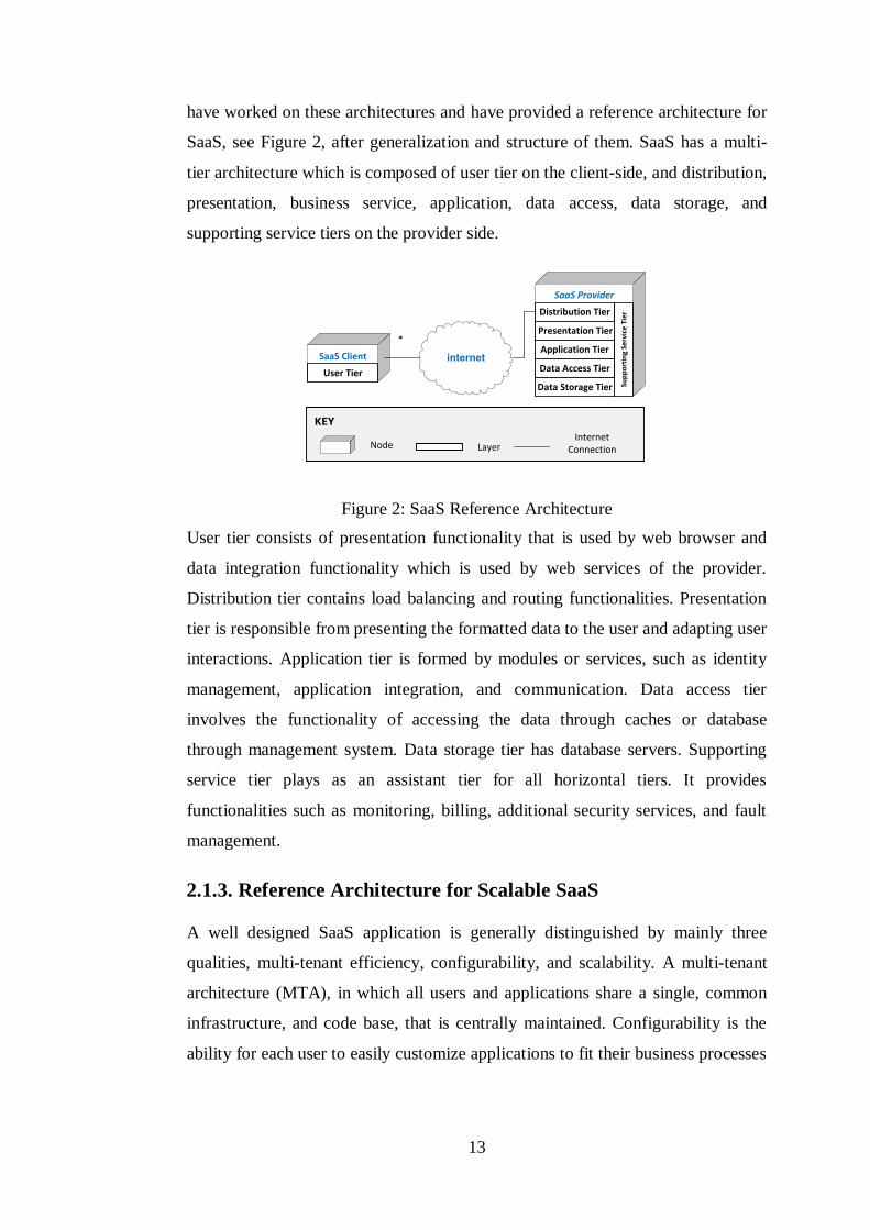
Figure 2: SaaS Reference Architecture ............................................................... 13
Figure 3: A traditional web application architecture ............................................ 14
Figure 4: Reference Architecture for Scalable SaaS ............................................ 15
Figure 5: Chart that shows aspects and number of inclusion ............................... 27
Figure 6: Chart that indicates tactics and their number of inclusion..................... 36
Figure 7: Conceptual model representing relation between General Resource
Model and Scalability Model .............................................................................. 39
Figure 8: Conceptual model presenting the relation between domain and UML
viewpoints .......................................................................................................... 40
Figure 9: The Resource Usage Framework ......................................................... 40
Figure 10: The scalability analysis domain model – Overview............................ 44
Figure 11: The relationship between the scalability concepts and GRM .............. 44
Figure 12: The scalability analysis domain model - Resource ............................. 45
Figure 13: The scalability analysis domain model – Workload ........................... 46
Figure 14: The scalability analysis domain model – Dynamic Usage .................. 48
Figure 15: Applying the Scalability Perspective ................................................. 63
Figure 16: Functional View of CHMS ................................................................ 80
Figure 17: Development View of CHMS ............................................................ 82
Figure 18: Development Views of CHMS after application of Scalability
Perspective. Left one is the current one and the right one will be the final version.
........................................................................................................................... 83
Figure 19: The deployment structure of CHMS .................................................. 84
Figure 20: User request low-level scenario – activity diagram representation ..... 89
Figure 21: User requests high-level scenario – sequence diagram representation 90
Figure 22: User request low-level scenario – activity diagram representation with
scalability annotations ........................................................................................ 92
Figure 23: User request high-level scenario – sequence diagram representation
with scalability annotations ................................................................................ 93
Figure 24: Annotated deployment model for CHMS ........................................... 94

xiii
List of Tables
Table 1: Publication Sources Searched ............................................................... 16
Table 2: Tactics and Aspects of SaaS ................................................................. 36
Table 3: Mapping scalability concepts to scalability domain ............................... 42
Table 4: Table that shows the instance that a tactic can be applied ...................... 48
Table 5: Mapping scalability domain concepts into UML equivalents in
collaboration-based approach ............................................................................. 49
Table 6: Mapping scalability domain concepts into UML equivalents in activity-
based approach ................................................................................................... 50
Table 7: Brief Description of Scalability Perspective .......................................... 59
Table 8: Applicability of Scalability Perspective to Architectural Views ............ 60
Table 9: Checklist Table ..................................................................................... 76
Table 10: Scalability Perspective Application for the Case Study ....................... 78

1
Chapter 1
Introduction
1.1. Background
1.1.1. Cloud Computing
The need for economical optimization of resources leads to various improvements
in the information technology. We have improved access to high-speed Internet.
Besides, we have realized significant developments in virtualization and
distributed computing. As a result, cloud computing has emerged, it has received
significant interest, and use of it has increased in recent years. It is an important
trend recently. It has not only changed today's computing resources,
infrastructure, platform, and software services, but also alters the way of
obtaining, managing, and delivering them for all participants, and also alters
technology and solutions contributing to realize that. The definition of it is “a
model for enabling convenient, on-demand network access to a shared pool of
configurable computing resources (e.g., networks, servers, storage, applications,
and services) that can be rapidly provisioned and released with minimal
management effort or service provider interaction” [37]. In this definition, the
most essential characteristics of cloud computing are identified as on-demand
self-service, resource pooling, broad network access, measured service and rapid
elasticity, respectively.
Cloud computing has a significant difference from traditional enterprise
applications. Instead of accessing the infrastructure, platform, and software within

2
the existing system, customers access them through cloud computing services
providing them from a central unit. These services are hosted and fully managed
by the providers. Consumers can buy the required amount of services on demand,
they can access the services and their data through any device over the Internet,
and they can use services without installation. Supplying resources as a service
from a central unit allows more cost-effective, flexible, and efficient computing. It
reduces hardware and software costs by leveraging cloud resources in a pay-as-
you-go way using virtual resources.
Cloud computing includes several categories of service, such as software as a
service (SaaS), platform as a service (PaaS), and infrastructure as a service (IaaS).
All of these services are offered on-demand over the Internet in a pay-as-you-go
model. Briefly, SaaS provides on-demand software applications, PaaS provides
on-demand software development platforms, and IaaS provides on-demand
computing infrastructures. Cloud taxonomy has other elements, such as cloud
software, service as a service, and cloud client. Cloud software is unique
purchased/packaged software used to build and run cloud services. Service as a
service is horizontal service that is subscribed to and used as a component of
SaaS, IaaS, or PaaS offerings, such as a billing service. Cloud client is client-
centric services and run-time software for cloud execution.
1.1.2. Software as a Service
Software as a Service (SaaS) is a web-based software distribution model that
delivers on-demand applications. It is the most mature the cloud service model,
since it evolved from the application-service-provider (ASP) model of software
hosting. The software is owned, hosted, and managed at a central site by the
service provider. It is accessed remotely over the Internet by multiple tenants. It
does not reside on client computers. Thus, users subscribe to the use of software
rather than acquiring it. And they pay for on a subscription basis as opposed to
purchasing it. Metric for subscription fee varies; it can be per month, per
document, per employee, etc.
3
Among IT business models SaaS is the only model that is growing in a double-
digit fashion, because it yields benefits for both service providers and end-users,
such as reduced cost, faster-time-to-market, anywhere access, and enhanced
scalability. From end-users perspective, instead of having to purchase hardware,
software, and the licenses in order to execute a specific application, they are just
subscribing to provider and using the application. So they have much lower and
predictable costs. In addition, SaaS offers high level of agility; the duration
between the time that an end-user identifies the need of having an application and
the time it finds the provider and it can start using that application is generally
very short. Another advantage is that an application become available at once and
can be reachable by all end-users all over the world. On the other hand, being
reachable increase the possibility for providers to reach the global market and
have more potential to grow their customer base. Finally, SaaS ensures cost
effective dynamic scalability. Executing processes that take a large amount of
resources is possible with more powerful hardware. Realization of this by multiple
end-users is hard in terms of cost and scalability. However, providers can increase
number of resources and they can upgrade them only once or few times in a year
more easily.
A SaaS application should have three key characteristics that are multi-tenancy,
configurability, and scalability [8]. Multi-tenancy is a software architecture
principle that offers a single instance of the software runs on a server to multiple
tenants. A tenant is a customer and each tenant has multiple users. Every tenant
experience application as if it were dedicated only to them. It allows computing
resources to be shared among tenants. Besides, SaaS can be configurable by
supporting customization. In other words, an end-user should have the ability to
alter a set of configuration options that affect functionality, communication, or
appearance of SaaS application. Each tenant may have its own settings for
configuration options. Lastly, we will explain scalability in detail in next section.
4
1.1.3. Scalability
Increase in the usage of cloud services brings new issues, challenges, and needs in
software analysis, design, development, testing, evaluation, and measurement due
to the crucial qualities, such as scalability. Scalability is the ability of a system to
handle a growing amount of task and to be adjustable to accommodate that growth
[48]. Scalability can be measured in various dimensions such as load, geographic,
functional, administrative, and generation scalability. Each dimension has the
same abstract purpose of having ability of handling more and less tasks
efficiently, yet these things depend on the dimension.
Functional scalability describes whether a functionality of a distributed
system can be easily expanded and contracted by adding or removing new
functional modules [48]. We can say a system is functional scalable if
software architecture of it can support addition and subtraction of
functional modules easily.
Load scalability describes whether hardware resources of a distributed
system can be easily expanded and contracted by adding or removing
resources in order to accommodate heavier or lighter loads [48]. We can
say a system is load scalable if it can cope with heavier data loads and also
can maintain its operation with fewer resources when it has lighter loads.
Functional scalability eases achieving load scalability.
Geographic scalability describes whether area of a distributed system can
be easily expanded and contracted by distributing into wider area or
assembling in a local area [48]. We can say a system is geographic
scalable if it can perform well even its service area is expanded and also
can maintain its operation with fewer resources when it services in a
limited area.
Administrative scalability describes whether a distributed system can be
easily shared and managed even when the number of users and tenants are
increased or decreased [48]. We can say a system is administrative
scalable if it can deal with high number of users and also can maintain its
operation with fewer resources when it has less number of users.
5
Generation scalability describes whether a distributed system can be easily
scaled up and down by adding and removing new generations of
components [48]. We can say a system is administrative scalable if it can
support addition and subtraction of components easily.
Providing scalability for a system is a time course that involves analysis, design,
and development phases [47]. Even execution of the system is included in this
duration, as demands for a system grow, new scalability requirements are born
and existing requirements need to be improved. Any fault in these phases may
lead to loss of customer, money, labor, and time due to unsatisfying scalability. A
software system that is not scalable for the recent demands will probably face
with breakdown. If this breakdown occurs frequently or longtime, customers will
give up using it and the company will lose money. In order to avoid this situation,
the company will probably try to redesign software architecture of the system and
will purchase new hardware, so this causes loss of time and labor.
Scalability has tight relation with other non-functional properties of a system,
such as performance, availability, and reliability. Scalability is usually come up
with performance; performance of a system has impact on scalability. However,
scalability is more than performance, since it does not only cover the existing
performance, but also answers what happens if the number of users becomes
bigger than the specified number. Even though a system can run in the normal
conditions now, when unprepared or unpredicted case for the system occurs, the
system may crash, and cannot service to its users until it is fixed or until the case
ends. Thus, availability and reliability is also affected by scalability.
Scalability was one of the underestimated non-functional requirements in the past.
Several products were successful but not sustainable due to their limitations on the
scale. However, a solid system needs to be able to handle also growing demands,
for example number of user for load scalability, and to be able to arrange itself
according to this grow. To be able to realize this quality architect of the system
needs to produce a well-design.

6
1.2. Problem Statement
We have identified the following problems in scalability analysis and design of
SaaS. Below we describe each problem separately.
Lack of a guideline that briefly presents all aspects of a SaaS system that
affects scalability and the most applied tactics to enable scaling easily.
Lack of a formal approach for scalability analysis models.
Lack of a guideline that explains the procedure of making a system
scalable.
Lots of studies have discussed their experience on SaaS scalability. These studies
have both common and distinct parts. A developer, who wants to scale its SaaS
system, should be able to understand where the problem is and to find the correct
solution alternatives easily and rapidly. In order to realize that there should be a
guideline study that gathers the most covered aspects and tactics addressed by
studies. These aspects and tactics should be explained briefly and clearly, and they
should be understandable. However, in the existing studies aspects of SaaS have
not been presented explicitly, they have usually focused on the tactics and
mentioned aspects in descriptions of tactics. Also, analytics about how many
times a tactic has been included in primary studies, and to which aspect it has
been addressed most should be covered.
Most of large-scale systems suffer from scalability, and the reason of that is; these
systems have not designed and implemented as a system that can handle larger
scale of demands. How system scalability is required to be should be described
before actually testing it in real life. Firstly, unambiguous, sufficient, detailed
information about system scalability should be obtained. Secondly, the scalability
requirements should be well understood. In order to achieve that, scalability
models of the system should be provided. Scalability models enable us to see both
run-time behavior and deployment of the system with scalability features. These
models should be obvious, concrete, testable, and they should also be
understandable by all of the stakeholders. Also, scalability modeling should be
made in a formal and systematic manner. Finally, analysis of system scalability

7
should be made in every phase of the system development. During this analysis
scalability requirements should be validated and modifications should be made.
Scalability is usually taken into consideration as a performance concern.
However, it should be studied in detail separately. We should be able to ensure
that the architecture exhibits the desired scalability properties via using existing
architectural views. Activities, tactics, and guidelines related to analysis and
design of system scalability should be precise. The steps to follow to be able to
assess scalability should be identified, so that the parts of the system that cannot
scale can be eliminated early, before testing the system with the participation of
stakeholders.
1.3. Approach
In order to provide a scalability guideline to address above problems, we have
initially needed to fetch brief, beneficial, and related information from high
number of primary studies. Instead of doing our domain research study in a
careless way, we have decided to follow Kitchenham’s guideline to perform
systematic literature review. This approach has provided us regular progress in
our research, and has enabled us to reach detailed and clear results. We have
started with defining our research questions, whose purpose is to understand the
aspects and tactics mentioned in the primary study. A search string to filter the
related primary studies while doing search operation in the database has been
constituted. We have assembled the primary studies that have been listed after
executing our search string on each search database. Then, we have eliminated the
false-positive ones by applying our exclusion criteria on studies. Finally, we have
analyzed the remaining studies while thinking our research questions. We have
acquired data from them to constitute list of aspects that affects SaaS scalability
and list of tactics that can be applied to make a SaaS system scalable. Then, we
have produced analytics on aspects and tactics described in studies.
In order to fulfill the issue in formal scalability modeling we have benefited from
the framework for quality analysis model offered by OMG. We have followed
8
their guideline format and have defined scalability domain and UML viewpoints.
Firstly, we have examined the general resource model and performance analysis
model, and then we have determined the elements that also take place in
scalability analysis. Secondly, we have extended our analysis on scalability
domain to define each unit involving in scalability. We have identified relations
among all scalability domain elements. Also, we have defined UML equivalents
of all domain elements which are stereotypes and association tags. Scalability
models have been derived from the viewpoint models of the system. They have
been constituted via placing defined stereotypes and association tags that include
specific scalability features.
We have thought that a procedure that explains the steps of achieving system
scalability can be achieved by defining a software architecture perspective. We
have adopted Rozanski and Woods’ architecture perspective catalogue. Defining a
perspective includes identifying applicability, concerns, activities, and problems.
Firstly, architecture viewpoints of the system should be evaluated whether they
require any modifications to provide scalability, and whether these modifications
are applicable. Concerns of scalability have been determined to be able to
evaluate and measure the quality. Activities have been constituted from five steps,
which are capturing scalability requirements, creating scalability models,
analyzing scalability, assessing scalability, and reworking architecture. We have
followed IEEE Software Engineering Book of Knowledge (SWEBOK) [26] to
carry out capturing scalability requirements. In creating scalability models we
have utilized from our UML profile for scalability. In analysis part we have
included both architecture design and code levels. We have adopted SAAM for
architecture design level analysis, and have benefited from some software testing
types, such as performance, load, spike testing. Finally, we have presented
common problems and pitfalls that are possible to occur during applying
scalability perspective.
Finally, we have provided application of scalability perspective on our case study,
Cloud Hotel Management System. We have presented architectural viewpoints of
9
the system, have described scalability requirements, and have provided scalability
analysis models.
1.4. Contribution
The contributions of this thesis can be defined as follows:
Systematic Literature Review (SLR) of SaaS Scalability
Up to now no studies have performed systematic literature review on the studies
related to SaaS scalability. Studies and resources on this topic are discrete, and
needs to be reviewed and assembled. We have detected this need and have filled
this gap. We have scanned all primary studies in search databases, have examined
99 of them residing in databases, and have selected 32 of them after applying our
exclusion criteria. We have constituted a list of aspects that affects SaaS
scalability and a list of tactics that can be applied to make a SaaS system scalable.
We have provided a description for each of aspects and tactics. Moreover, we
have provided analytics that involve the number of occurrence an aspect is
contained or the number of occurrence a tactic is presented.
UML Profile for Scalability
We have found out that scalability analysis modeling should have rules and
standards, so that people can use scalability models in a unique and formal way to
reveal problems before testing their systems. We have extended framework for
quality analysis model offered by OMG and have defined UML Scalability Profile
based on General Resource Model (GRM). Thus, we have provided a tool for
scalability assessment for the stakeholders. In order to realize this profile we have
defined scalability domain viewpoint to understand and to cover domain well, and
we have also defined stereotypes and association tags, which describe domain
concepts, are used in UML models.
Software Architecture Perspective for Scalability
Scalability quality of the system is closely related to performance and has
presented together in the existing studies. We have claimed that scalability should
be separated and we have defined architectural perspective for scalability. We
10
have extended Rozanski and Woods’ architectural perspective catalog. We have
identified concerns of scalability and we have defined the steps to apply the
perspective. We have presented a study that will guide you to achieve your system
scalability. We have also provided a chapter that explains application of the
perspective for a case study.
1.5. Outline of the Thesis
This thesis is organized as follows: Chapter 2 provides background information
for SaaS architecture and presents systematic literature review made on studies
related to scalable architectures for SaaS. We present the results of our research
and provide a list of aspects that affect scalability of SaaS and a list of tactics to
achieve scalability of SaaS. Chapter 3 introduces UML profile for scalability that
is based on general resource model. Firstly, background information about
general resource and scalability analysis modeling is given. Then, domain
viewpoint is defined using scalability concepts. Also, stereotypes and associated
tags are defined while mapping domain viewpoint elements to UML equivalents.
In Chapter 4, software architecture perspective for scalability is presented. Firstly,
definitions and overview of the perspective is given. Then, parts, such as
concerns, activities, and problems are examined in detail. Chapter 5 presents our
case study, Cloud Hotel Management System, in order to show application of
information given in previous chapters on a real system. Chapter 6 gives the
related work. Finally, Chapter 7 presents the conclusions and discussions.
11
Chapter 2
Software as a Service Architecture
for Scalability
2.1. Software as a Service Architecture
2.1.1. Reference Architecture
Reference software architecture represents the structures and respective elements,
and relations provide templates for concrete architectures in a particular domain
or in a family of software systems [9]. It utilizes reference model which is an
abstract framework aiming to encourage clear communication includes a set of
clearly defined terms and concepts linking together. It provides a template based
on the generalization of a set of solutions. Each of reference architecture is formed
for a particular domain. Reference architecture is beneficial for people and
organizations that work in the same domain. Concrete architecture is formed on
the basis of it. Reference architecture accelerates the design of concrete
architecture and implementation by reusing an effective architecture. Concrete
architecture uses business requirements, and system requirements are also
included since they are used by reference architecture. Figure 1 shows the
conceptual model that represents reference architecture and its factors.

12
Implementation
Related
Standards
Principles
Guidelines
Patterns
Best Practices
includesDriven by
Drivers
Motivation
BusinessRequirements
Mission & Vission
Goals & Objectives
fulfils follows uses
SystemRequirements
Architecture
Reference Architecture
Reference Model
Concrete Architecture
utilizes
uses
uses
Figure 1: A conceptual model representing reference architecture and its factors
2.1.2. Reference Architecture for SaaS
Software provided by SaaS provider is rent and accessed through internet by
multiple clients. Basic SaaS architectures are often variations of the classic three-
tier web application hosting model that contains presentation, application, and
data tiers. Traditional web application architecture is illustrated in Figure 3.
Distribution tier has a load balancer and web servers that handle HTTP requests.
Application tier has a load balancer and application servers that run business
logic. Data tier consists of master, slave, and backup database servers. Thus, this
architecture has already been designed to scale out by adding additional hosts at
the persistence or application layers and has built-in performance, failover and
availability features.
Increase in SaaS adoption as well as the new technology innovations has
significantly evolved SaaS architecture. Now, SaaS applications may have
different purpose and design priorities such as reliability, security, availability,
performance, scalability, and cost. Design priorities of three-tier architecture are
typically availability and cost, so it is not sufficient for all purposes. A study made
by Tekinerdoğan and Öztürk [53] have examined various architectures and
addressed reference architecture of SaaS. Many architecture structures harvest a
set of patterns which have been in a number of successful implementations. They
13
have worked on these architectures and have provided a reference architecture for
SaaS, see Figure 2, after generalization and structure of them. SaaS has a multi-
tier architecture which is composed of user tier on the client-side, and distribution,
presentation, business service, application, data access, data storage, and
supporting service tiers on the provider side.
internetSaaS Client
User Tier
SaaS Provider
Distribution Tier
Presentation Tier
Application Tier
Data Access Tier
Data Storage Tier Sup
po
rtin
g Se
rvic
e T
ier
*
KEY
Node LayerInternet
Connection
Figure 2: SaaS Reference Architecture
User tier consists of presentation functionality that is used by web browser and
data integration functionality which is used by web services of the provider.
Distribution tier contains load balancing and routing functionalities. Presentation
tier is responsible from presenting the formatted data to the user and adapting user
interactions. Application tier is formed by modules or services, such as identity
management, application integration, and communication. Data access tier
involves the functionality of accessing the data through caches or database
through management system. Data storage tier has database servers. Supporting
service tier plays as an assistant tier for all horizontal tiers. It provides
functionalities such as monitoring, billing, additional security services, and fault
management.
2.1.3. Reference Architecture for Scalable SaaS
A well designed SaaS application is generally distinguished by mainly three
qualities, multi-tenant efficiency, configurability, and scalability. A multi-tenant
architecture (MTA), in which all users and applications share a single, common
infrastructure, and code base, that is centrally maintained. Configurability is the
ability for each user to easily customize applications to fit their business processes

14
without affecting the common infrastructure. To support scalability the
application is installed on powerful or/and multiple machines. In order to
distribute the system efficiently application should have a scalable architecture.
Reference architecture for scalable SaaS is illustrated in Figure 4. Using scalable
architectures in applications have various advantages, such as handling peak load
behavior and addition of new features [1]. You can overcome problems that
emerge during viral events. You can leverage the scalability the cloud affords to
make the most productive use of development and testing time when introducing
new features to an application. You can absorb sudden increases in processing
time due to the addition of new features by scaling to accommodate the increased
load they impart on the system until you can isolate and optimize the performance
bottlenecks. It is not uncommon for new features to place unexpected loads on a
system when they are introduced. Exhaustive testing of the performance
characteristics of these new features before release may be possible, but this often
comes with significant cost both in time to market as well as in infrastructure and
manpower.
MasterDB
LB
Web Server Web Server
LB
Clients
App Server App Server App Server
Slave DB
BackupDB
Figure 3: A traditional web application architecture

15
Zone #1 Zone #n
Clients
MasterDB
Web Server Web Server
Slave DB
BackupDB
...
...Cache Server
LB #nLB #1
App ServerApp Server
LB
Web Server Web Server
LB
App Server App Server
Slave DB
...
Cache Server
...
DNS
Figure 4: Reference Architecture for Scalable SaaS
2.2. Systematic Literature Review
We have aimed to analyze and have defined the key concerns related to SaaS and
scalability. Our research method has adopted systematic literature review in which
we have selected 32 primary studies. As a result of the data extraction and
synthesis process of the systematic literature review we have provided a list that
characterizes the various important concerns with respect to scalability and SaaS.
The outcome of the paper can be useful for both practitioners and researchers to
know the current scalability aspects and tactics.
After the observation that some aspects of the SaaS has impact on the scalability,
and there are some techniques that can be applied to provide scalability of SaaS.
To identify the aspects that have impact on scalability of SaaS and approaches to
achieve scalability we have conducted a systematic literature review using the

16
guidelines as described by Kitchenham [33]. In particular we have interested in
the answers to the following research questions:
RQ1: What are the factors that affect scalability in SaaS?
RQ2: What are the current approaches for achieving scalability in SaaS?
Our search scope has included all the papers that were published in 2003 to 2014.
We have searched for full papers in selected venues that publish high quality
papers. We have used the following search databases: IEEE Xplore, ACM Digital
Library, Wiley Inter Science Journal Finder, ScienceDirect, ISI Web of
Knowledge, Springer, and other channels including Microsoft Academic Search
and manual search channels. These venues are listed in Table 1. Our targeted
search items are journal papers, conference papers, and workshop papers.
Table 1: Publication Sources Searched
Source
Number of Included
Studies
After Applying Search
Query
Number of Included
Studies After
Exclusion Criterion
IEEE Xplore 33 17
ACM Digital Library 5 3
Wiley Interscience 3 0
Science Direct 1 0
ISI Web of Knowledge 16 2
Springer 25 4
Other Channels 16 6
Total 99 32
To search the selected databases we have used both manual and automatic search
strategies. Automatic search has been realized through entering search strings on
the search engines of the electronic data source. Manual search has been realized
through manually browsing the conferences, journals or other important sources
and checking the references of selected papers. The manual searches have
appeared to be quite useful since we retrieved some good-quality articles that an
automatic search could not reveal.
The adopted search string is as follows:

17
("Document Title": scalability OR "Document Title": scalable OR "Document
Title": scaling)
AND
("Document Title": architecture OR "Document Title": software OR "Document
Title": SaaS OR "Document Title": "Software as a Service")
AND
("Abstract": cloud OR "Abstract": SaaS OR "Abstract": "Software as a Service")
The result of the overall search process after applying the search queries and the
manual search is shown in the second column of Table 1. As it can be seen from
the table we could identify 99 papers at this stage of the search process. After the
initial set of exclusion, we are unable to find any papers that discuss this issue.
In accordance with the SLR guidelines [33] we have further applied an exclusion
criterion on the large number of papers in the first stage. The overall exclusion
criteria that we have used are as follows:
Abstract or title does not explicitly primarily discuss scalability
Not a primary study
The primary study does not consider SaaS architecture in particular
Repeated in an already mined source
Most of the content is repeated in a similar paper (Extended version is
chosen over the shorter one)
The exclusion criteria have been checked by a manual analysis by both of the
authors. According to the best of our knowledge, there has been no secondary
study related to aspects and approaches for scalability of SaaS. After applying the
exclusion criteria 32 papers of the 99 papers remained. For data extraction and
synthesis process as required by the systematic review protocol we have
thoroughly studied the primary studies in detail to answer our two defined
research questions. The answers to the research questions have been described in
the following paragraphs in which we have provided a short summary of each
identified primary study with the basic conclusions.

18
2.3. Data Extraction
In order to extract data needed to answer research questions, we have read the
full-texts of 32 selected primary studies. We have designed a data extraction form
to collect all the information needed to address the review questions and the study
quality criteria. The data extraction form has included standard information such
as study ID, document title, year, authors, repository, and contribution type. In
order to collect information directly related to answering research questions, we
have added some fields such as targeted domain, motivation for study, main
theme of study, aspects that affect scalability of SaaS, and approaches to achieve
scalability of SaaS. We have kept a record of the extracted information in a
spreadsheet to support the process of synthesizing the extracted data.
2.3.1. Aspects
An aspect is a particular part or feature of SaaS. Based on the primary studies we
could identify the following key aspects that impact the scalability of SaaS;
capacity, database access, network traffic, data management, disk architecture,
data architecture, data model, workload, migration, fault-tolerance and recovery,
software architecture, multi-tenancy, application complexity, and levels of
scalability mechanisms.
2.3.1.1. Capacity
Capacity describes quantity and quality of hardware resources and specifications
of the system software. The scalability of the system is in direct proportion with
the capacity. Computing hardware resources, such as RAM, CPU, disk, memory,
network bandwidth, the number of concurrent TCP connections the server can
support, operating system, software resource allocation and utilization, define the
capacity of the system. The scalability of the system is in direct proportion with
the capacity [45]. As the power of resources increase or the number of the nodes
increase the system can scale more. The need to host scalable systems leads to
emergence of large-scale data centers comprising thousands to hundreds of
thousands of compute nodes.

19
2.3.1.2. Database Access
The communication between components in business layer and database server is
done via database access. The components obtain and save the required data
through this connection, which makes data access the key aspect of scalability in
the multi-tenant SaaS [58]. It will be the bottleneck of a SaaS system, if accessing
a database is not efficient and is slow [23]. Database connection can be either
direct or indirect. Direct access allows applications to perform necessary database
operations directly, so scalability technique is done for the entire system. For
instance, Database integrated SaaS, which is a SaaS system fully integrated with a
database, has direct access, such as Salesforce.com [6]. On the other hand, in the
indirect access to database there is a middle layer, APIs provided by database
services, between business components and underlying database server. Indirect
access allows the software and database to have its own scalability mechanism.
For example, kernel-based SaaS, which is a SaaS system running on top of kernel
that runs on top of databases. Any communication between software applications
and databases occurs via the kernel, such as Corenttech.com [23].
2.3.1.3. Network Traffic
Another crucial issue in SaaS scalability is network traffic, which is the flow of
data around a network. Data is encapsulated in network packets. Major concerns
of network traffic that have impact on scalability include latency, packet size,
packet count, and packet loss. Latency is a time interval between the stimulation
and response. It is affected by both communication hardware specifications and
distance between servers and clients. High distance leads to high latency. When
latency in network traffic increases, response time of the system increases as well
[24]. Packet loss occurs when one or more packets of data travelling across a
network fail to reach their destination. It is typically caused by network
congestion. It reduces the throughput of the system. Packet size and count is
proportional to the workload created by users. As the number of users increases
the latency and packet losses may increase. Thus, increase in these concerns

20
causes a decrease in system performance and makes achieving scalability more
difficult [46].
2.3.1.4. Data Management
Data is the mostly essential in cloud computing systems and it is the element that
systems should handle heavier or lighter loads of data efficiently. In order to
satisfy scalability data management should be carried out in a scalable manner.
Data management comprises all the disciplines related to managing data as a
valuable resource, such as development, execution of plans that control the data
[38]. Data management has mainly two topics that affect scalability, disk
architecture and data architecture.
2.3.1.4.1. Disk Architecture
Data storage is one of the central issues to achieve system scalability. Data is
stored in disks, but storing data in scalable way is determined by disk architecture.
Disk architecture is a distributed computing architecture. A distributed system is a
software system in which components located on networked
computers communicate and coordinate their actions by passing messages. Two
most common cloud database architectures are shared disk and shared nothing.
Shared disk architecture (SD) is a distributed computing architecture where all
disks are accessible from all cluster nodes [2]. Since the persistent data is stored
and shared in network attached storage (NAS), it is a candidate for single point of
failure. However, it has some advantages that affect system scalability. It does not
need migration. It is utilized for their ability to abstract replication, fault-
tolerance, consistency, and independent scaling of the storage layer from the
DBMS logic. On the other hand, in shared nothing architecture (SN) each node is
independent, self-sufficient, and has sole access to distinct disks, generally locally
attached storage, and there is no single point of contention across the system [60].
None of the nodes shares memory or disk storage. So if one of the instances is
down, the requests of users will be forward to another node and the process is
transparent to users. SN is popular for web development because of its scalability.
A pure SN system can scale almost infinitely simply by adding nodes in the form
21
of inexpensive computers, since there is no single bottleneck to slow the system
down. A SN system typically partitions its data among many nodes on different
databases assigning different computers to deal with different users or queries, or
may require every node to maintain its own copy of the application's data, using
some kind of coordination protocol. This is often referred to as database sharding.
Both the load balance and the fault-tolerance requirements can be addressed. Also
live migration requires that all database components are migrated between nodes,
including physical storage files.
2.3.1.4.2. Data Architecture
In SaaS a single application instance of the software is shared among multiple
independent users. A well-designed SaaS application is scalable, multi-tenant-
efficient, and configurable. To satisfy these qualities it needs to have scalable and
multi-tenant data architecture. Data architecture contains models, policies, rules or
standards that specify data structure, determine which data is collected, and
manage the way how it is stored, arranged, integrated, and put to use in systems.
A component of data architecture, database, is an organized collection of data.
Three data architecture models that implement and manage scalable multi-tenancy
are separate databases, shared database-separate schemas, and shared database-
shared schema [28]. Separate databases are stored on distributed shared-nothing
environment [7].
A database should be scaled when it can no longer meet baseline performance
metrics, as when too many users are trying to access the database concurrently or
the size of the database is causing queries and updates to take too long to execute,
or when operational maintenance tasks start to affect data availability. So
providing scalable data model is crucial for all multi-tenant cloud computing
systems and is a grand challenge for a decade.
Separate databases were the first general solution that is able to deal with large
datasets stored on distributed shared-nothing environment [7]. Computing
resources and application code are generally shared between all the tenants on a

22
server, but each tenant has its own set of data that remains logically isolated from
data that belongs to all other tenants. It is easy to customize the data model of the
system for each tenant’s needs and to restore tenant’s data from backups in case of
a failure. However, these systems have some disadvantages, they require higher
hardware costs for maintaining equipment and backing up tenant data and they
cannot scale beyond a few machines as the performance degrades dramatically
due to synchronization overhead and partial failures. The second approach, shared
databases-separate schemas, involves housing multiple tenants in the same
database, with each tenant having its own set of tables that are grouped into a
schema created specifically for the tenant. Like the isolated approach, the
separate-schema approach is relatively easy to implement, and tenants can extend
the data model as easily as with the separate-database approach. A third approach
involves using the same database and the same set of tables to host multiple
tenants' data.
2.3.1.4.3. Data Model
A data model organizes data elements and standardizes how the data elements
relate to one another [20]. There are various data models used currently by
software systems, such as relational, object, document, etc. The choice of data
model has impact on the database scalability that directly affects system
scalability. For instance, a SaaS system can scale from dozens to thousands or
even more number of tenants that may have their particular needs. This case
brings major challenges to databases. To achieve scalability a database should be
able to handle the increase of both data and request accompanied with the growth
of tenants. While providing this it should maintain meeting the particular needs of
one tenant efficiently and safely without affecting the others.
In relational model all data is represented in terms of tuples grouped into relations.
Relational database, whose data is organized using relational model, have some
obstacles to be able to achieve scalability. Although relational databases scale
well on a single server node, during the past decade there has been a growing
concern that RDBMSs cannot easily scale-out from a few machines to hundreds

23
or even thousands of machines and fails to provide adequate tools and guidance
[2]. Thus, the need of scalability and multi-tenant support in SaaS makes
traditional RDBMS unappealing and calls for a better data storage solution [20].
RDBMS represents the bottleneck of a SaaS system and introduces single point of
failure, since it severely limits the scalability of SaaS.
In a key/value database, schemas and relationships between tables are not
explicitly defined unlike a relational database, and therefore it is more flexible
when scaling to larger number of server nodes. Modern scalable cloud storage
systems, such as BigTable, Dynamo, and Cassandra has key-value data model.
2.3.1.5. Workload
Data, previously stored locally and only available to one single tenant, now
require much larger storage and available to multi-tenants, since SaaS systems
store bigger in both individual file size as well as total number of files and serves
to multi-tenants. Thus, this change in data storage yields a challenge in workload
and storage of systems, scalability problems. Workload influences many
application characteristics such as software architecture and algorithm. Workload
depends on the number of currently online access clients, the total load forms
from every user’s network traffic and application service usage. There are three
types of workload and require different scalability mechanisms [23], OLAP,
OLTP, and mixed type. In OLAP type workload a high portion of the requests are
reading data from the system. Read operations are usually with the purpose of
querying historical data and analysing it [21]. In this case, the system should be
able to scale in case of high volume of read operations. In OLTP write operations
are dominant operations. Although many SaaS applications require rare updates,
there are many cases for OLTP like Facebook and Salesforce. Users of both
systems update their enterprise data, profiles, pictures or status frequently. In this
case, the system should be able to distribute the write operations to avoid
bottleneck at a single node. Finally, in mixed type the portion of read and write
operations can be close and the architecture needs to be designed to ensure there is

24
no bias towards either type of operations to be able to satisfy scalability
requirements.
2.3.1.6. Migration
The process of transferring data between nodes is called migration. It is usually
performed automated to facilitate people’s task. Data migration occurs for a
variety of reasons including server or storage replacements or upgrades to get
better performance. It can be done online or offline [23]. While the system is
operational migrating data is defined as online migration and it is more
problematic than offline migration that is done when the SaaS shuts down its
services for maintenance. Data migration basically consists of two processes that
are data extraction where data is read from old node and data loading where data
is written to a new node. Data to be moved is critical in terms of amount and the
location of data, since it influences the scalability of the system. To achieve
scalability there are some strategies, such as minimizing amount of data to
minimize the bandwidth demand, moving to the closest node to minimize latency
delay [2].
2.3.1.7. Fault-Tolerance and Recovery
Fault-tolerance determines the ability of a system to maintain its operation
properly in the case of the failure of some of its components, such as processors or
storage. The data in the failed components can be obtained and corrected via
recovery process. The causes of failure may be physical or logical damage. The
solution for fault-tolerance and recovery affects the system scalability [23], and if
an appropriate solution is not chosen the system may suffer. The solution should
include detection of the nodes failed. The system should scale down without a
significant performance downgrade, when a node fails. And when the failed node
comes back to the system, it should automatically scale up and recover to previous
working status.
25
2.3.1.8. Software Architecture
Scalability of SaaS systems is not only determined by the available resources, but
also by software architects' early design decisions. Software architecture is the set
of structures needed to reason about the software system, and comprises the
software elements, the relations between them, and the properties of both
elements and relations [9]. Scalability is impacted by how the control and data
flow of the application or service is designed and implemented [23]. If software
system is not well-designed, it cannot satisfy scalability and it needs expensive re-
implementations [47]. A well-designed software architecture that satisfies
scalability depends on the features of the system. Since each system has different
features there is no one scalable software architecture design. For example, [23]
classifies SaaS systems into four categories, such as Database integrated SaaS,
Kernel-based SaaS, Service-oriented SaaS, and PaaS-based SaaS. All of them
have different software architecture. We explain them in approaches section.
2.3.1.9. Multi-Tenancy
SaaS is characterized by its multi-tenancy architecture (MTA) that enables the
sharing a single application instance of the software runs on a server among
multiple independent users [34]. The term tenant refers to a group of users sharing
the same view on an application. This view includes the data they access, the
application configuration, the user management, particular functionalities, and
related non-functional properties. MTA provides flexible customization to
individual tenant. Each tenant runs the customized instance of SaaS that is
designed to virtually partition its data and configuration while sharing the
hardware, the operating system, the middleware and the application components
[23]. However, the multi-tenancy architecture and customization requirements
have brought up challenges in SaaS scalability. These challenges mainly comprise
the high number of concurrent accesses from the users and handling large amount
of tenants effectively in addition the amount of data for an application that rises
rapidly.
26
2.3.1.10. Application Complexity
Another significant topic in SaaS that needs high levels of scalability is the way of
processing large-scale data sets [23]. Storing and saving efficiently or blindly
adding hardware resources may not necessarily yield the desired scalability in the
system, since the data is obtained to process and to make operations on it and then
save it. To be able to process effectively brings out the algorithms and makes the
scalability of a system closely related to the underlying algorithm or computation.
Algorithm of the implementation defines application complexity that specifies the
difficulty level of an application. An application can be implemented with
different ways using different algorithms. It affects time takes for realization of a
task, so performance and scalability of a system is affected by it. So there occurs a
need for designing algorithms and mechanisms that are inherently scalable.
Algorithms that implement parallel approach offer greater portability,
manageability and compatibility of applications and data and address the
scalability issues.
2.3.1.11. Levels of Scalability Mechanisms
The architects can achieve the total scalability of the SaaS by taking on scalability
of each tier of the SaaS having multi-layers separately [23]. Scaling a tier means
applying a scalability technique to a tier. The techniques applied to a tier may be
different for each single tier, because each tier has its own constraints and
objectives. Furthermore, a tier of the architecture includes third-party business
services, so the scalability of these services can be solved solely in its design.
Figure 5 shows the chart that indicates names of each aspect and their number of
inclusion in primary studies.
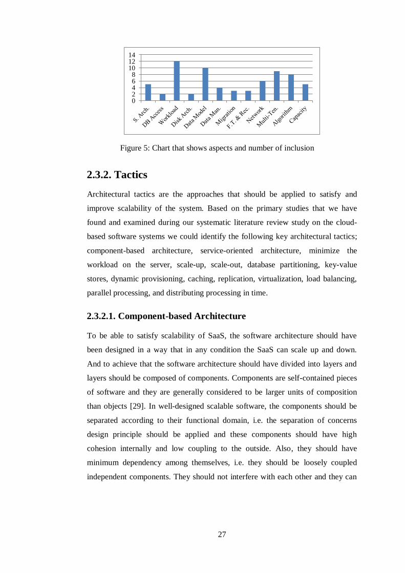
27
Figure 5: Chart that shows aspects and number of inclusion
2.3.2. Tactics
Architectural tactics are the approaches that should be applied to satisfy and
improve scalability of the system. Based on the primary studies that we have
found and examined during our systematic literature review study on the cloud-
based software systems we could identify the following key architectural tactics;
component-based architecture, service-oriented architecture, minimize the
workload on the server, scale-up, scale-out, database partitioning, key-value
stores, dynamic provisioning, caching, replication, virtualization, load balancing,
parallel processing, and distributing processing in time.
2.3.2.1. Component-based Architecture
To be able to satisfy scalability of SaaS, the software architecture should have
been designed in a way that in any condition the SaaS can scale up and down.
And to achieve that the software architecture should have divided into layers and
layers should be composed of components. Components are self-contained pieces
of software and they are generally considered to be larger units of composition
than objects [29]. In well-designed scalable software, the components should be
separated according to their functional domain, i.e. the separation of concerns
design principle should be applied and these components should have high
cohesion internally and low coupling to the outside. Also, they should have
minimum dependency among themselves, i.e. they should be loosely coupled
independent components. They should not interfere with each other and they can
0 2 4 6 8
10 12 14
28
be developed in parallel, i.e. they are stateless. This approach ensures that when a
component or a layer causes being a bottleneck in the scalability, the developer
can easily intervene in that component or that layer to fix it using a scalability
approach. It facilitates applying scale-out, load balancing, and replication [35].
2.3.2.2. Service-oriented Architecture
Service-oriented architecture (SOA) is a software architecture design pattern that
is composed of services, pieces of software providing application functionality
[30]. As we indicate in previous approach in order to provide excellent scalability
of SaaS, each part of the application should be able to be independently scaled
[57]. Thus, it is necessary to avoid coupling in the architecture so that a change in
a part of the software system should not affect other parts [23]. SOA achieve this,
since services are unassociated units of functionality that are self-contained. SOA
also provides asynchrony meaning system can perform useful work while waiting
for input and output to complete, and concurrency meaning tasks can be done in
parallel taking advantages of the distributed nature of hardware and software.
2.3.2.3. Minimize the Workload on the Server
Most of the cloud-based SaaS applications have some similar operations, such as
making a request, authorization of the requests, fetching data from the database,
inserting or updating or deleting data, validation of data, and making some
operations, calculations, merging, etc. on data. These operations are either done
in the client or in the server. If all of these operations are done in the server, then
server may become unresponsive, even unavailable. Scaling-up the server solves
this problem just temporarily, since as the demands grow the server always needs
to be scaled-up and it is costly. The correct way to handle this problem is to move
the workload from the server to the clients as much as possible and minimize the
workload on the server [23], [47].

29
2.3.2.4. Scale-up
To cope with dynamically increasing demands from multiple tenants, the first
approach that comes to mind is scaling the system vertically (scaling-up). It
means to add resources to a single node in a system, typically involving the
addition of processors or memory to a single computer [48]. In order to be
scalable, the more nodes are added to the system, the higher the achievable
throughput should be. When adding new hardware to the platform, the total
capacity of the entire environment increases, becoming more scalable for not just
a single customer, but for the entire client base. Such vertical scaling of a system
also enables to use virtualization approach more effectively, as it provides more
resources for the operating system and application modules to share [2]. Also, in
order to avoid service outages, a system needs to allocate computing resources for
the application dynamically.
2.3.2.5. Scale-out
The other and a popular approach that includes hardware addition is scaling
horizontally (scale-out). It means to add more nodes to a system, such as adding a
new server to a distributed server cluster [48]. Vertical scalability is addressed by
increasing the power of nodes whereas horizontal scalability uses more nodes for
the same job. It provides a more cost effective and smooth scalability versus
scale-up approach [22]. When more computing power is required, a multi-tenant
architecture makes it easy to increase capacity. Since SaaS platform consists of
many tenants and all tenants share the same application and data store, and tenants
are usually distributed to servers.
2.3.2.6. Database Partitioning
In order to support scalability of SaaS and real-time high performance computing
we apply divide-and-conquer principle to the software architecture. When this
principle has applied to databases, it means tenant data are partitioned well in the
back-end database so that processing and I/O can be done in parallel, and data can
be repartitioned easily. Partitioning is the process of pruning subsets of the data
30
from a database and moving the pruned data to other databases or other tables in
the same database [8]. You can partition a database by relocating whole tables, or
by splitting one or more tables up into smaller tables horizontally or vertically.
Horizontal partitioning means that the database is divided into two or more
smaller databases using the same schema and structure, but with fewer rows in
each table. Two most widely used horizontal partitioning methods are application-
based distribution keys in which choosing one or more attributes as a distribution
key according to domain knowledge and tenant-used distribution keys where
stores each tenant’s data in a single partition. Vertical partitioning means that one
or more individual tables are divided into smaller tables with the same number of
rows, but with each table containing a subset of the columns from the original.
Partitioning is also an example of scale-out approach, since in order to improve
the efficiency the number of databases or tables is increased [58].
In a multi-tenant SaaS data scaling approach for the data model aspect differs,
since the approach you choose for your SaaS application's data architecture will
affect the options available to you for scaling it to accommodate more tenants or
heavier usage [8]. The scalability patterns address the different challenges posed
by scaling shared databases and dedicated databases. For separate databases single
tenant scale-out approach is applied. Shared database approaches are well-suited
to the tenant-based horizontal partitioning pattern, because each hardware
resource has its own set of data, so the managers can easily target individual
tenant data and move it to another server.
Existing systems show that partitioning can effectively increase the scalability of
database systems, by parallelizing I/O or by assigning each partition to separate
workers in a cluster. Data partitioning is a proved technique that database systems
provide to physically divide large logical data structures into smaller and easy
manageable pieces (chunks) [54]. The data inside a database can be distributed
across one or more partitions. Horizontal partitioning is writeable operation
preferable, while column store and vertical partitioning is optimal for read

31
operations. Also, a hybrid approach is used in SaaS that involves both read and
write operations.
2.3.2.7. Key-value Stores
As we see in previous section most of the aspects of the SaaS are related to
database, and this indicates us database comes out as being a bottleneck for the
scalability. In a multi-tenant environment that has high number of requests,
database must be able to execute large requests with low response times and also
redistribute data and load on the new hardware. To be able to satisfy these
requirements of the database and scale data layer successfully key-value stores are
used [2]. Key-value stores (KVS) allow the application to store its data in a
schema-less way. In KVS data is viewed as key-value pairs and atomic access is
supported only at the granularity of single keys. Since the data could be stored in a
data type of a programming language, there is no need for a fixed data model. In
DBMS all data within a database is treated as a whole and it is the responsibility
of the DBMS to guarantee the consistency of the entire data. In the context of key-
value stores this relationship is completely severed into key-values where each
entity is considered an independent unit of data or information and hence can be
freely moved from one machine to the other. Also, single key atomic access
semantics naturally allows efficient horizontal data partitioning. Moreover, the
design of the key-value stores provides dynamic provisioning in the presence of
load fluctuations easily. On the other hand, traditional DBMS are more
appropriate for static provisioning. Due to the above desirable properties of key-
value stores, they have almost limitless scalability. Key-value stores can be
applied either from the beginning of the system setup or leveraging from it during
using the conventional DBMS architecture.
2.3.2.8. Dynamic Provisioning
By adding new resources to system or partitioning data we just guarantee
scalability of the system for a while. However, there is another challenge in SaaS;
the system should provide scalability even sudden load fluctuations on an
application or a service due to demand surges happens [2]. The basis of the

32
mechanism that respond to sudden is dynamic provisioning which includes
deploying and instantiating the server computing instances from a centralized
administrative console. Briefly, this mechanism should make the system maintain
and avoid any interruption. Dynamic provisioning mechanism uses scalability
approaches dynamically, i.e. a system can be scaled-up dynamically by adding
more nodes or can be scaled-down by removing nodes, and this is called as
elasticity. With dynamic provisioning processing can be shifted to off-peak hours.
2.3.2.9. Caching
Caching is a common practice of storing data in a medium holding smaller
amounts of data but which can deliver it faster than a secondary complete source
when future requests are made [32]. The purpose of caching is to be able to serve
data faster when dealing with thousands of requests per second. By serving data
faster throughput of the system is increased, response time is decreased, and
scalability can be satisfied. Almost every application can be configured to use
caching either as a built in feature or third party library. Also, caching can be done
in any tier, but generally the application tier caches database state for quick local
access. The data to be cached is determined according to percentage and time of
use of data. Data that has frequent use or recent use has the priority of caching.
The probability of data being used increases when it just has been recently used,
because it is the most likely data to be used in the near future. For read-intensive
applications, caching approach can provide large performance gains, great
scalability as application processing time and database access is reduced. On the
other hand, write-intensive applications usually do not see as a great benefit, but
solutions that include modifications to caching approach exist. For SaaS systems
distributed caching, the extension of caching applied to multiple servers, is used.
Distributed caching is scalable because of the architecture it employs [32]. It
distributes its tasks across multiple servers. Since caching mechanism is much
simpler than a DBMS, usage of distributed cache avoids the scalability problems
that a database usually faces.

33
2.3.2.10. Replication
In a system in order to increase availability and performance, and also to be fault-
tolerant the same data can be stored on multiple software or hardware
components, this operation is called replication [23]. Replication is typically
applied in databases. Since when running a high traffic site, one of the biggest
bottlenecks becomes the database. In order to solve this problem and to achieve
scalability of database, replication is applied as one of the most common
techniques. In replication technique all or part of the data in a database is copied
to another database, and then these replicas are kept synchronized with the
original. This provides increasing the availability of the data, so that processes or
threads that are waiting in the queue to be able to do some operation with data do
not need to wait anymore. Since there are multiple copies of data, it can reach it
from the next available one. However, the type of the operation is an issue that is
needed to take care on. If the operation is writing, then to provide the consistency
of data all of the copies need to be updated when one of them is changed. And this
brings another workload to the database layer, so it may not be helpful for the
scalability. Thus, replication of data is recommended for mostly read-type
operations in terms of scalability perspective.
There is another type of replication in terms of the place the replication occurs,
replicating application. Components in the application layer or the whole
application layer can be stored on multiple server instances. Thus, workload on
the application layer can be distributed to multiple machines and processed
concurrently by each of the application instances, so a performance improvement
can be satisfied and it can reply to more number of requests without performance
degradation. Moreover, to support dynamically increasing demands from multi-
tenants, the cloud service providers have to duplicate computing resources
dynamically to cope with the fluctuation of requests from tenants. This is
currently handled by virtualization and duplication at the application level in the
existing cloud environment [55].
34
For instance, in horizontal scaling (scale-out) to distribute workload application
instances are replicated onto multiple nodes, also data is replicated onto multiple
database servers. The important point is careful data placement, since it minimizes
the response times.
2.3.2.11. Virtualization
As we mentioned in scale-up approach increasing the number of resources in the
system, also increases the performance of the system and lead to satisfy
scalability. Resources can be provided to the system by not only plugging in the
server machine. The resources of the system that is comprised of OS, memory,
storage, network, etc. can be virtualized and creating a virtual of something is
called virtualization. It allows the ability to run multiple systems on a single
physical system or one operating system on multiple physical systems. To be able
to dynamically respond to increasing demands of the multi-tenants virtualization
is widely used in current cloud computing systems. Since virtualization needs to
replicate the OS, middleware and application components for each customer, it is
often insufficient to provide SaaS [49].
2.3.2.12. Load Balancing
With an increased number of end users, the performance of a SaaS degrades and it
is necessary to distribute client requests to different servers in order to perform
parallel processing and provide scalability. The process of distributing workloads
across multiple computing resources is referred as load balancing. Its purpose is to
optimize resource usage, maximize throughput, minimize response time, and
avoid overload of any one of the resources. In most of the existing SaaS, client
requests towards web servers are distributed using a front-end load balancer [60].
Load balancer that is either hardware or software distributes traffic over web
servers. To do better load balancing among partitions of a database or application
servers, an effective algorithm that can migrate, distribute and duplicate tenants
among partitions through monitoring the load is highly desirable.
35
2.3.2.13. Parallel Processing
In multi-tenant environment the SaaS has high number of requests from users, and
in order to respond to all of these requests in a very short time, an approach that
improves SaaS scalability should be followed. A request is composed of many
tasks, including computing operations, database access, etc. In order to be able to
reduce execution time of tasks and to reduce the workload of each component, the
tasks should be grouped and executed in a parallel and asynchronous manner [47].
MapReduce, a programming model for processing large data sets with a parallel
algorithm on a cluster, is an example of this manner [54]. It is a good example of
data-intensive computing, requiring task coordination, and is heavily linked to
distributed storage. Many applications can be broken down into sequences of
MapReduce jobs. A map task runs through each element of a list and produces a
new list, and reduce applies a new function to a list, reducing it to a single final
value or output.
2.3.2.14. Distributing Processing in Time
Software systems have wavy usage plots, since clients access the system
randomly. However, for some periods there will be an excessive usage of the
system. These periods can be hourly, daily, monthly, seasonally, etc. or randomly.
The cause of these periods may be that being a specific time for the domain of that
system. This excessive usage leads to peak load on the server and causes low
response time and scalability problems. To overcome this problem the first thing
to do is reducing the system load, and you may postpone some of the workload to
other times in your processing cycle [47]. Some of the tasks on the server occur
continually at all times of day or night, and some of them is not urgent, or not
need to do real-time, so these tasks can be postponed to other times. Since the
total workload will be reduced during the peak load times, you will achieve
performance and scalability improvement. You can realize the tasks postponed
during quieter times, and you can also utilize from your idle resources.
Figure 6 shows the chart that indicates names of each tactic and their number of
inclusion in primary studies.
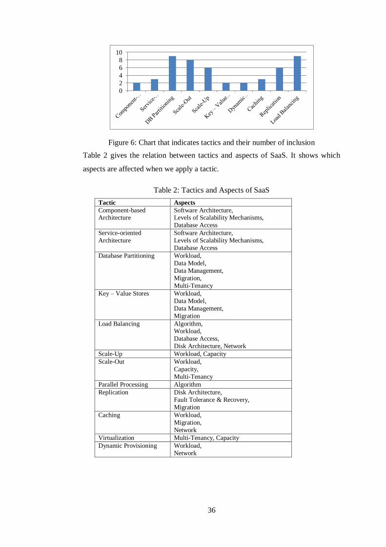
36
Figure 6: Chart that indicates tactics and their number of inclusion
Table 2 gives the relation between tactics and aspects of SaaS. It shows which
aspects are affected when we apply a tactic.
Table 2: Tactics and Aspects of SaaS
Tactic Aspects
Component-based Architecture
Software Architecture, Levels of Scalability Mechanisms,
Database Access
Service-oriented
Architecture
Software Architecture,
Levels of Scalability Mechanisms,
Database Access
Database Partitioning Workload,
Data Model,
Data Management,
Migration,
Multi-Tenancy
Key – Value Stores Workload,
Data Model,
Data Management,
Migration
Load Balancing Algorithm, Workload,
Database Access,
Disk Architecture, Network
Scale-Up Workload, Capacity
Scale-Out Workload,
Capacity,
Multi-Tenancy
Parallel Processing Algorithm
Replication Disk Architecture,
Fault Tolerance & Recovery,
Migration
Caching Workload,
Migration,
Network
Virtualization Multi-Tenancy, Capacity
Dynamic Provisioning Workload,
Network
0
2
4
6
8
10
37
Chapter 3
UML Profile for Scalability
3.1. UML Profile
UML model is used to represent viewpoints of software architecture that depicts
both static and dynamic behaviors of the system [41]. Deployment viewpoint
depicts static structure of the system, deployment of software on hardware
resources. Activity and sequence models which are used to depict dynamic
behavior, such as information flow. UML has been developed as an open
extensible modeling language, and the intention and usage of its extension
mechanisms has been described at an early stage. Two types of extensions are
devised; lightweight extensions, based on stereotypes, tagged values, and
constraints, and heavyweight extensions, based on direct modifications of the
UML meta-model. In our study we take the first approach. A profile in UML for a
software quality is a customized version, lightweight extension, of these UML
models in order to present analysis of the quality. It contains stereotypes, tag
definitions, and constraints, having quality information, applied to model
elements. In theory a UML profile can be defined for any non-functional attribute
of software and hardware systems in order to model quality of service with its
distinctive properties. Creating UML profile consists of two parts; defining a
domain model, which is a UML-independent description of the structural and
behavioral patterns that characterize the considered domain, and mapping the
concepts introduced in the domain model onto a UML viewpoint, which is a
specification of how the domain elements are realized in UML. The resulting
UML viewpoint is made of stereotypes, tags and constraints.

38
3.2. Modeling Scalability
Scalability modeling is the process of creating a model for a system that contains
scalability specifications. In order to do scalability modeling sufficient
information about system scalability should have been obtained. It describes how
the scalability will be for a system without actually testing it in real life. It is
created by software development engineers and system engineers, and it is used
by all of the stakeholders. All of the large-scale systems need to determine,
analyze, and create scalability models in the design phase and update them during
system development iterations. Since these systems include a lot of detailed
requirements, large numbers of stakeholders, multiple hardware platforms,
distribution of components over several hardware platforms, high concurrency,
and high complexity of interaction between components [47]. The purposes of
scalability modeling include the following set:
To make scalability requirements and estimations more understandable,
visual, manageable, and easier for the stakeholders.
To be able to see both run-time behavior and deployment of the system
with scalability features.
To provide a tool for scalability assessment for the stakeholders.
To identify resources that cannot achieve scalability. These resources may
have the following properties:
o have high response time,
o unable to support addition and removal of another resource or
unable to upgrade them,
o may face with heavier workload,
o have complex, unambitious definition.
Scalability models are derived from the viewpoint models of the system. To
indicate scalability critical elements deployment viewpoint of the system should
be used. Scalability requirements should be mapped to this view, and features of
elements, such as process, network links, data storages, that need to be scalable,
should display its scalability data. As an example for scalability data, we can say
response time of functional elements and resources, the request latency between

39
processes, duration of a database operation, the number of concurrent requests
that each element can handle. Moreover, we can also present run-time behavior of
the system by using sequence and activity diagrams. We can specify scalability
requirements of functional modules and resources that are in action and
communication with others.
To be able to create scalability models in a formal way, we define UML
Scalability Profile based on General Resource Model (GRM). Figure 7 shows the
conceptual model representing the relation between GRM and scalability model.
In next sections, we firstly explain GRM, then UML Scalability Profile.
GeneralResourceModel ScalabilityModel
UMLViewpoint
supports
DomainViewpointuses
DomainViewpoint UMLViewpointuses
Figure 7: Conceptual model representing relation between General Resource
Model and Scalability Model
3.2. General Resource Model (GRM)
As in other run-time qualities in scalability context resource has higher impact and
importance than other aspects, since scalability is directly proportional to the
capacity of hardware resources. So general resource model (GRM) is the thing we
need while describing the scalability domain. GRM is a framework for modeling
systems with the usage of quality of service (QoS) information [43]. QoS
information represents, either directly or indirectly, the physical properties of the
hardware and software environments of the application represented by the model.
GRM has two viewpoints, domain and UML viewpoints. Domain viewpoint
describes the common structural and behavioral concepts and patterns that
characterize a system. UML viewpoint defines the realization way of the elements
of domain model using UML. It consists of a set of UML extensions, such as
stereotypes, constraints, tagged values, and is supplemented by specifications of
the mappings of the domain concepts to those extensions. Figure 8 shows the
conceptual model presenting the relation between domain and UML viewpoints.
GRM provides mostly abstract concepts that are not applied directly to elements
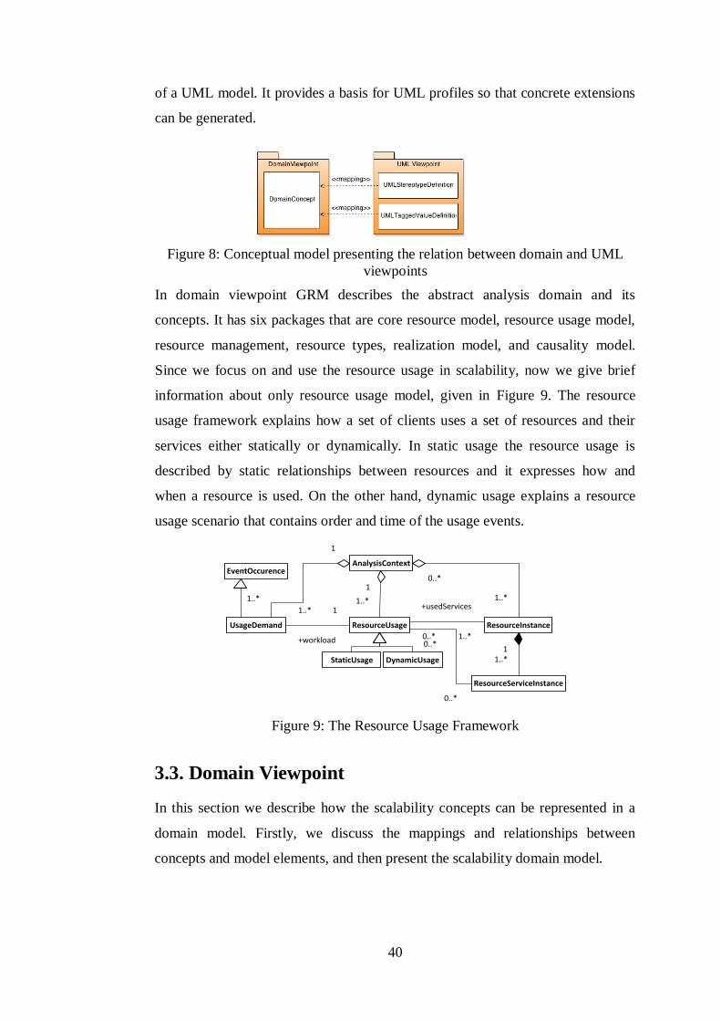
40
of a UML model. It provides a basis for UML profiles so that concrete extensions
can be generated.
Figure 8: Conceptual model presenting the relation between domain and UML
viewpoints
In domain viewpoint GRM describes the abstract analysis domain and its
concepts. It has six packages that are core resource model, resource usage model,
resource management, resource types, realization model, and causality model.
Since we focus on and use the resource usage in scalability, now we give brief
information about only resource usage model, given in Figure 9. The resource
usage framework explains how a set of clients uses a set of resources and their
services either statically or dynamically. In static usage the resource usage is
described by static relationships between resources and it expresses how and
when a resource is used. On the other hand, dynamic usage explains a resource
usage scenario that contains order and time of the usage events.
EventOccurence
UsageDemand
AnalysisContext
1
1..*
ResourceUsage
1
1..*
StaticUsage DynamicUsage
ResourceInstance
ResourceServiceInstance
11..*
0..*
1..*
1
+workload
1..*
0..*
+usedServices
1..*0..*
0..*
Figure 9: The Resource Usage Framework
3.3. Domain Viewpoint
In this section we describe how the scalability concepts can be represented in a
domain model. Firstly, we discuss the mappings and relationships between
concepts and model elements, and then present the scalability domain model.
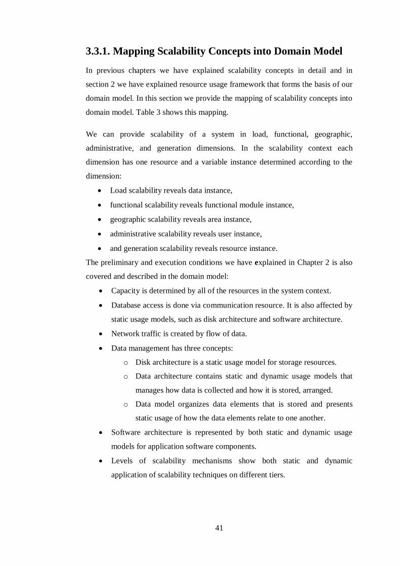
41
3.3.1. Mapping Scalability Concepts into Domain Model
In previous chapters we have explained scalability concepts in detail and in
section 2 we have explained resource usage framework that forms the basis of our
domain model. In this section we provide the mapping of scalability concepts into
domain model. Table 3 shows this mapping.
We can provide scalability of a system in load, functional, geographic,
administrative, and generation dimensions. In the scalability context each
dimension has one resource and a variable instance determined according to the
dimension:
Load scalability reveals data instance,
functional scalability reveals functional module instance,
geographic scalability reveals area instance,
administrative scalability reveals user instance,
and generation scalability reveals resource instance.
The preliminary and execution conditions we have explained in Chapter 2 is also
covered and described in the domain model:
Capacity is determined by all of the resources in the system context.
Database access is done via communication resource. It is also affected by
static usage models, such as disk architecture and software architecture.
Network traffic is created by flow of data.
Data management has three concepts:
o Disk architecture is a static usage model for storage resources.
o Data architecture contains static and dynamic usage models that
manages how data is collected and how it is stored, arranged.
o Data model organizes data elements that is stored and presents
static usage of how the data elements relate to one another.
Software architecture is represented by both static and dynamic usage
models for application software components.
Levels of scalability mechanisms show both static and dynamic
application of scalability techniques on different tiers.
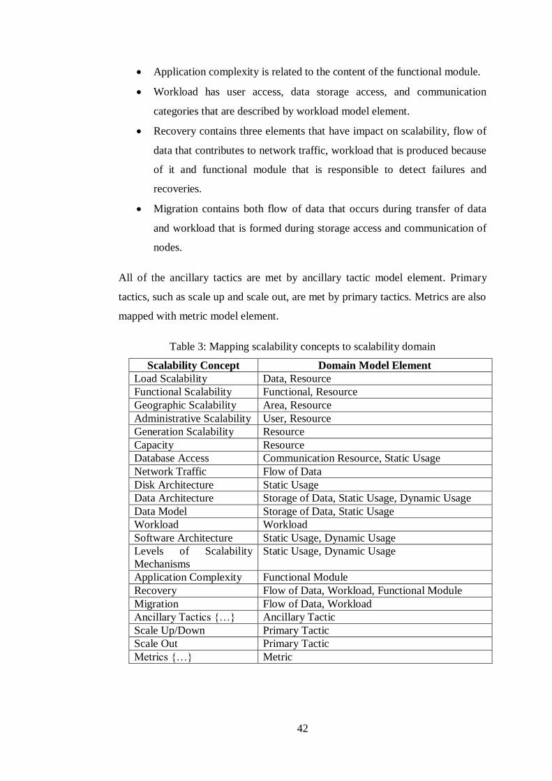
42
Application complexity is related to the content of the functional module.
Workload has user access, data storage access, and communication
categories that are described by workload model element.
Recovery contains three elements that have impact on scalability, flow of
data that contributes to network traffic, workload that is produced because
of it and functional module that is responsible to detect failures and
recoveries.
Migration contains both flow of data that occurs during transfer of data
and workload that is formed during storage access and communication of
nodes.
All of the ancillary tactics are met by ancillary tactic model element. Primary
tactics, such as scale up and scale out, are met by primary tactics. Metrics are also
mapped with metric model element.
Table 3: Mapping scalability concepts to scalability domain
Scalability Concept Domain Model Element
Load Scalability Data, Resource
Functional Scalability Functional, Resource
Geographic Scalability Area, Resource
Administrative Scalability User, Resource
Generation Scalability Resource
Capacity Resource
Database Access Communication Resource, Static Usage
Network Traffic Flow of Data
Disk Architecture Static Usage
Data Architecture Storage of Data, Static Usage, Dynamic Usage
Data Model Storage of Data, Static Usage
Workload Workload
Software Architecture Static Usage, Dynamic Usage
Levels of Scalability
Mechanisms
Static Usage, Dynamic Usage
Application Complexity Functional Module
Recovery Flow of Data, Workload, Functional Module
Migration Flow of Data, Workload
Ancillary Tactics {…} Ancillary Tactic
Scale Up/Down Primary Tactic
Scale Out Primary Tactic
Metrics {…} Metric
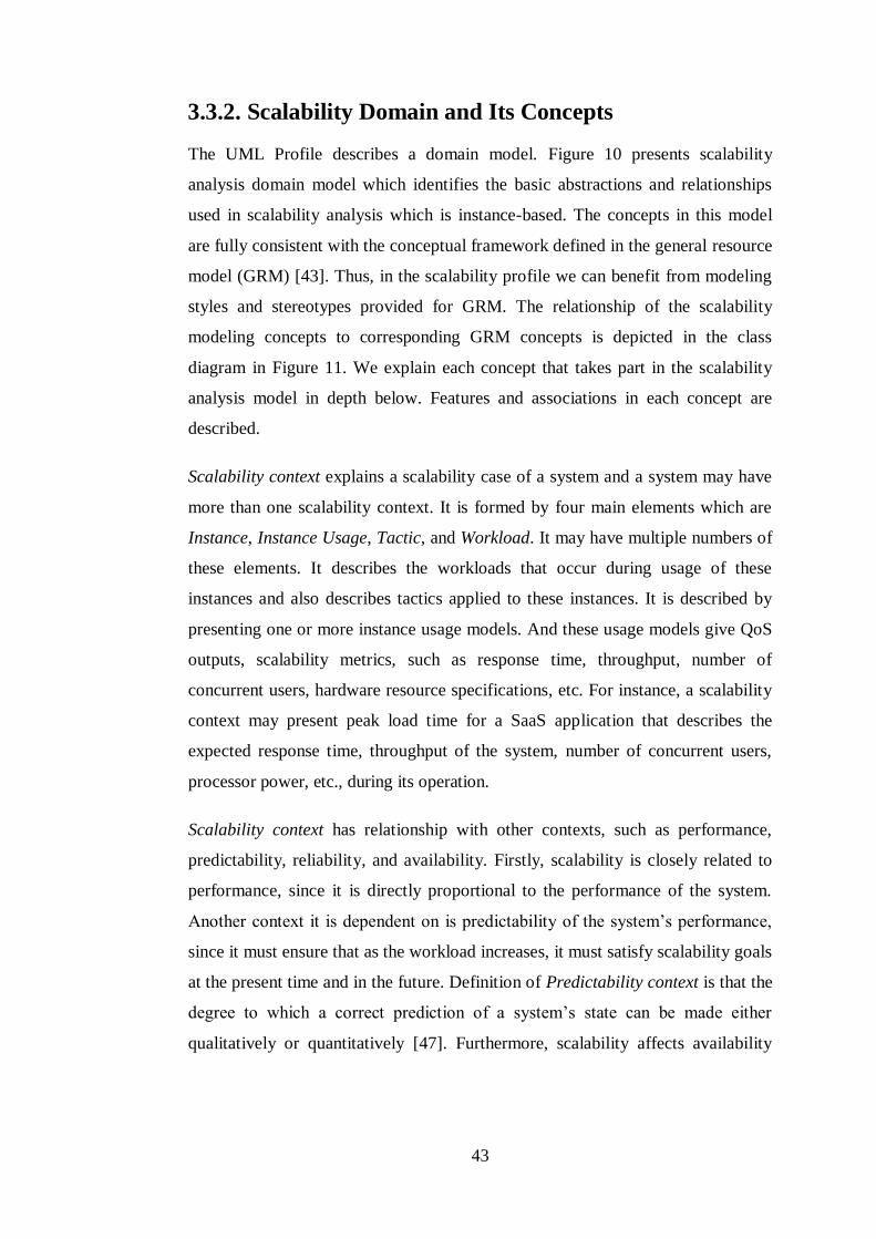
43
3.3.2. Scalability Domain and Its Concepts
The UML Profile describes a domain model. Figure 10 presents scalability
analysis domain model which identifies the basic abstractions and relationships
used in scalability analysis which is instance-based. The concepts in this model
are fully consistent with the conceptual framework defined in the general resource
model (GRM) [43]. Thus, in the scalability profile we can benefit from modeling
styles and stereotypes provided for GRM. The relationship of the scalability
modeling concepts to corresponding GRM concepts is depicted in the class
diagram in Figure 11. We explain each concept that takes part in the scalability
analysis model in depth below. Features and associations in each concept are
described.
Scalability context explains a scalability case of a system and a system may have
more than one scalability context. It is formed by four main elements which are
Instance, Instance Usage, Tactic, and Workload. It may have multiple numbers of
these elements. It describes the workloads that occur during usage of these
instances and also describes tactics applied to these instances. It is described by
presenting one or more instance usage models. And these usage models give QoS
outputs, scalability metrics, such as response time, throughput, number of
concurrent users, hardware resource specifications, etc. For instance, a scalability
context may present peak load time for a SaaS application that describes the
expected response time, throughput of the system, number of concurrent users,
processor power, etc., during its operation.
Scalability context has relationship with other contexts, such as performance,
predictability, reliability, and availability. Firstly, scalability is closely related to
performance, since it is directly proportional to the performance of the system.
Another context it is dependent on is predictability of the system’s performance,
since it must ensure that as the workload increases, it must satisfy scalability goals
at the present time and in the future. Definition of Predictability context is that the
degree to which a correct prediction of a system’s state can be made either
qualitatively or quantitatively [47]. Furthermore, scalability affects availability
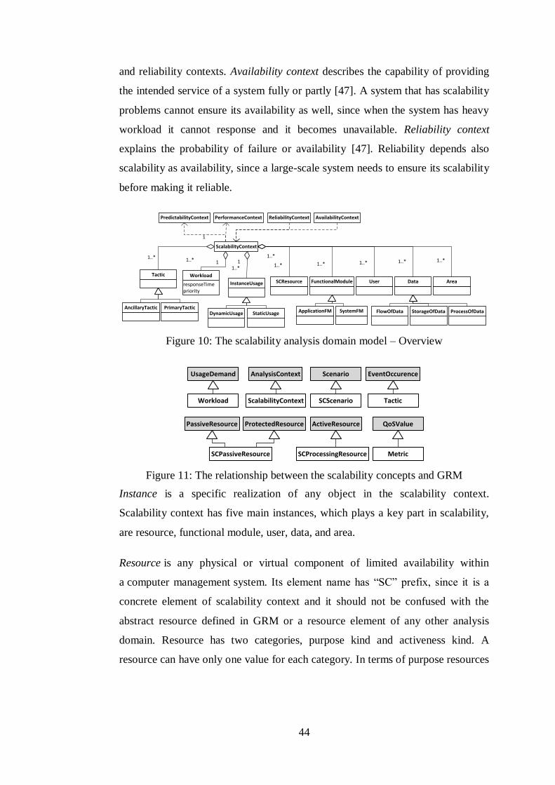
44
and reliability contexts. Availability context describes the capability of providing
the intended service of a system fully or partly [47]. A system that has scalability
problems cannot ensure its availability as well, since when the system has heavy
workload it cannot response and it becomes unavailable. Reliability context
explains the probability of failure or availability [47]. Reliability depends also
scalability as availability, since a large-scale system needs to ensure its scalability
before making it reliable.
responseTimepriority
Workload
11..*
ReliabilityContext AvailabilityContextPredictabilityContext
User
ScalabilityContext
InstanceUsage
11..*
1..*
1..*
SCResource FunctionalModule
DynamicUsage StaticUsage
Data
ApplicationFM SystemFM FlowOfData StorageOfData ProcessOfData
1
1..*
AreaTactic
PerformanceContext
AncillaryTactic PrimaryTactic
1..* 1..* 1..* 1..*
Figure 10: The scalability analysis domain model – Overview
UsageDemand
Workload
AnalysisContext
ScalabilityContext
Scenario
SCScenario
PassiveResource ProtectedResource ActiveResource
SCProcessingResourceSCPassiveResource
EventOccurence
Tactic
QoSValue
Metric
Figure 11: The relationship between the scalability concepts and GRM
Instance is a specific realization of any object in the scalability context.
Scalability context has five main instances, which plays a key part in scalability,
are resource, functional module, user, data, and area.
Resource is any physical or virtual component of limited availability within
a computer management system. Its element name has “SC” prefix, since it is a
concrete element of scalability context and it should not be confused with the
abstract resource defined in GRM or a resource element of any other analysis
domain. Resource has two categories, purpose kind and activeness kind. A
resource can have only one value for each category. In terms of purpose resources

45
include processor, storage, and communication. Processor represents either virtual
or physical processing devices capable of storing and executing program code.
Storage resources represent the device for storing data, such as disk, memory, etc.
Communication resources provide communications, flow of data, between
resources. A resource is used during the operation time of the system. Thus,
according to usage activeness, it is either processing or passive resource. Passive
resources can only respond to requests or stimulus, they cannot behave
themselves. Processing resources can generate stimuli concurrently without being
prompted by an explicit stimulus instance. You can see the scalability resource
model in Figure 12.
StorageProcessor Communication
utilizationthroughput
SCResource
processingRatecontextSwitchTimepriorityRangeisPreemptible
SCProcessingResource
waitingTimeresponseTimecapacityaccessTime
SCPassiveResource
activenessKind purposeKind
MemoryDisk
Figure 12: The scalability analysis domain model - Resource
Functional Module is any set of machine-readable instructions that directs
a computer's processor to perform specific operations. It controls the resources
and data flow of the system. It exists both at the client-side and server-side. It is
divided into two, application and system functional module (FM). Application FM
uses the computer system to perform special functions. System FM is designed to
directly operate the computer hardware, to provide basic functionality needed by
users and other software, and to provide a platform for running application
software.
Data is a set of values of qualitative or quantitative variables. It is either the result
of measurements or information given by the user. It is separated into three
categories according to its place in the context that are flow of data, storage of
data, and process of data. Flow of data, which flows through the system network,
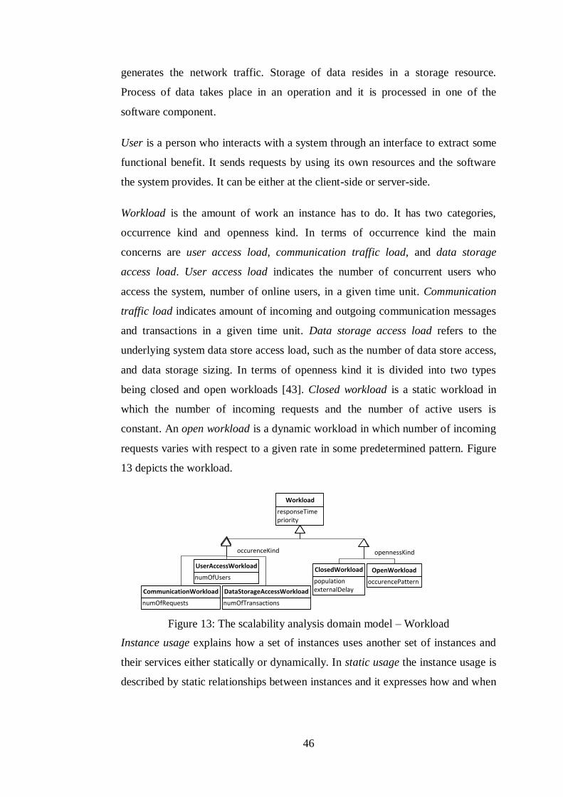
46
generates the network traffic. Storage of data resides in a storage resource.
Process of data takes place in an operation and it is processed in one of the
software component.
User is a person who interacts with a system through an interface to extract some
functional benefit. It sends requests by using its own resources and the software
the system provides. It can be either at the client-side or server-side.
Workload is the amount of work an instance has to do. It has two categories,
occurrence kind and openness kind. In terms of occurrence kind the main
concerns are user access load, communication traffic load, and data storage
access load. User access load indicates the number of concurrent users who
access the system, number of online users, in a given time unit. Communication
traffic load indicates amount of incoming and outgoing communication messages
and transactions in a given time unit. Data storage access load refers to the
underlying system data store access load, such as the number of data store access,
and data storage sizing. In terms of openness kind it is divided into two types
being closed and open workloads [43]. Closed workload is a static workload in
which the number of incoming requests and the number of active users is
constant. An open workload is a dynamic workload in which number of incoming
requests varies with respect to a given rate in some predetermined pattern. Figure
13 depicts the workload.
numOfUsers
UserAccessWorkload
numOfRequests
CommunicationWorkload
numOfTransactions
DataStorageAccessWorkload
occurenceKind
occurencePattern
OpenWorkload
populationexternalDelay
ClosedWorkload
opennessKind
responseTimepriority
Workload
Figure 13: The scalability analysis domain model – Workload
Instance usage explains how a set of instances uses another set of instances and
their services either statically or dynamically. In static usage the instance usage is
described by static relationships between instances and it expresses how and when

47
an instance is used. On the other hand, dynamic usage explains an instance usage
whose details are determined by a scenario that contains order and time of the
usage events. Dynamic usage domain model is presented in Figure 14. A scenario
is an ordered series of steps called action executions. A step may be an elementary
operation or a complex sub-scenario composed of many basic steps. It may
include a scalability requirement or estimation like hardware resource
specification, response times, or throughputs. Execution of scalability scenario
produces workload on the system and also produces metrics as outputs, QoS
values. Metrics, which are the result types of execution of a scenario, are
monitored to be able to measure scalability of service, such as response time,
throughput, requests per second, number of users, CPU usage, memory usage,
network usage. These metrics can have four different types, such as a measured
value, an estimated value, an assumed value, and a required value. A measured
value is determined by monitoring the system while running. An estimated value
is calculated by a tool. An assumed value is assigned by a human, determined
according to its experience. A required value is specified in the system
requirements. Metrics are included in the stereotype attributes. During the
execution of a scenario we can see the change in values of these metrics,
describing the scalability of the system.

48
hostExecutionDemandresponseTime
SCScenario
probabilityrepetitiondelayoperationsintervalexecutionTime
SCStep
1
+{ordered}
1..*
1
+root
1
+predecessor0..*
+successor
0..*
responseTimepriority
Workload
1..*
1 0..*
+host
0..1
«deploys»
Metric
DynamicUsage
Data
processingRatecontextSwitchTimepriorityRangeisPreemptible
SCProcessingResource
1
+root
1
1..* 1..*
User
1..*
Area
1..*
FunctionalModule
Tactic
1..*
1..*
Figure 14: The scalability analysis domain model – Dynamic Usage
Tactic is the approach that should be applied to satisfy scalability of the system. It
presents possible solutions in case of the system does not show its required quality
properties the perspective addresses. Tactic is divided into two categories,
ancillary and primary tactics. Table 4 shows the relation between tactics and
instances. In the right column it has the instance names that the tactic in the left
column can be applied to.
Table 4: Table that shows the instance that a tactic can be applied
Tactic Instance
Scale-up/down SCResource
Scale-out SCResource
Load Balancing SCResource,
FunctionalModule
Parallel Processing SCResource,
FunctionalModule
Virtualization SCResource
Dynamic Provisioning SCResource
Multi-tiered Architecture FunctionalModule
Component-based
Architecture
FunctionalModule
Service-oriented
Architecture
FunctionalModule
Caching FunctionalModule, Data
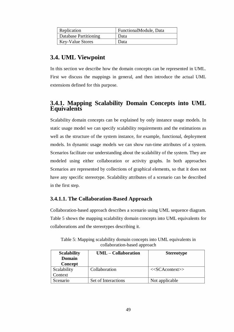
49
Replication FunctionalModule, Data
Database Partitioning Data
Key-Value Stores Data
3.4. UML Viewpoint
In this section we describe how the domain concepts can be represented in UML.
First we discuss the mappings in general, and then introduce the actual UML
extensions defined for this purpose.
3.4.1. Mapping Scalability Domain Concepts into UML Equivalents
Scalability domain concepts can be explained by only instance usage models. In
static usage model we can specify scalability requirements and the estimations as
well as the structure of the system instance, for example, functional, deployment
models. In dynamic usage models we can show run-time attributes of a system.
Scenarios facilitate our understanding about the scalability of the system. They are
modeled using either collaboration or activity graphs. In both approaches
Scenarios are represented by collections of graphical elements, so that it does not
have any specific stereotype. Scalability attributes of a scenario can be described
in the first step.
3.4.1.1. The Collaboration-Based Approach
Collaboration-based approach describes a scenario using UML sequence diagram.
Table 5 shows the mapping scalability domain concepts into UML equivalents for
collaborations and the stereotypes describing it.
Table 5: Mapping scalability domain concepts into UML equivalents in
collaboration-based approach
Scalability
Domain
Concept
UML – Collaboration Stereotype
Scalability
Context
Collaboration <<SCAcontext>>
Scenario Set of Interactions Not applicable
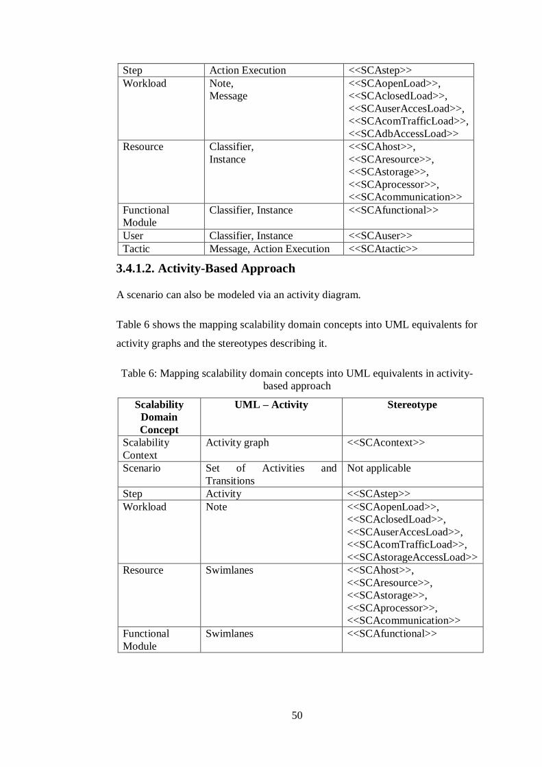
50
Step Action Execution <<SCAstep>>
Workload Note,
Message
<<SCAopenLoad>>,
<<SCAclosedLoad>>,
<<SCAuserAccesLoad>>,
<<SCAcomTrafficLoad>>,
<<SCAdbAccessLoad>>
Resource Classifier,
Instance
<<SCAhost>>,
<<SCAresource>>,
<<SCAstorage>>,
<<SCAprocessor>>,
<<SCAcommunication>>
Functional
Module
Classifier, Instance <<SCAfunctional>>
User Classifier, Instance <<SCAuser>>
Tactic Message, Action Execution <<SCAtactic>>
3.4.1.2. Activity-Based Approach
A scenario can also be modeled via an activity diagram.
Table 6 shows the mapping scalability domain concepts into UML equivalents for
activity graphs and the stereotypes describing it.
Table 6: Mapping scalability domain concepts into UML equivalents in activity-
based approach
Scalability
Domain
Concept
UML – Activity Stereotype
Scalability
Context
Activity graph <<SCAcontext>>
Scenario Set of Activities and
Transitions
Not applicable
Step Activity <<SCAstep>>
Workload Note <<SCAopenLoad>>,
<<SCAclosedLoad>>,
<<SCAuserAccesLoad>>,
<<SCAcomTrafficLoad>>,
<<SCAstorageAccessLoad>>
Resource Swimlanes <<SCAhost>>,
<<SCAresource>>,
<<SCAstorage>>,
<<SCAprocessor>>,
<<SCAcommunication>>
Functional
Module
Swimlanes <<SCAfunctional>>
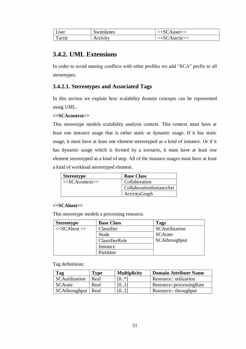
51
User Swimlanes <<SCAuser>>
Tactic Activity <<SCAtactic>>
3.4.2. UML Extensions
In order to avoid naming conflicts with other profiles we add “SCA” prefix to all
stereotypes.
3.4.2.1. Stereotypes and Associated Tags
In this section we explain how scalability domain concepts can be represented
using UML.
<<SCAcontext>>
This stereotype models scalability analysis context. This context must have at
least one instance usage that is either static or dynamic usage. If it has static
usage, it must have at least one element stereotyped as a kind of instance. Or if it
has dynamic usage which is formed by a scenario, it must have at least one
element stereotyped as a kind of step. All of the instance usages must have at least
a kind of workload stereotyped element.
Stereotype Base Class
<<SCAcontext>> Collaboration
CollaborationInstanceSet
ActivityGraph
<<SCAhost>>
This stereotype models a processing resource.
Stereotype Base Class Tags
<<SCAhost >> Classifier SCAutilization
SCArate
SCAthroughput Node
ClassifierRole
Instance
Partition
Tag definitions:
Tag Type Multiplicity Domain Attribute Name
SCAutilization Real [0..*] Resource:: utilization
SCArate Real [0..1] Resource::processingRate
SCAthroughput Real [0..1] Resource:: throughput

52
<<SCAresource>>
This stereotype models a passive resource.
Stereotype Base Class Tags
<<SCAresource >> Classifier SCAutilization
SCAcapacity
SCAaxTime
SCArespTime
SCAwaitTime
SCAthroughput
Node
ClassifierRole
Instance
Partition
Tag definitions:
Tag Type Multiplicity Domain Attribute Name
SCAutilizati
on
Real [0..*] Resource::utilization
SCAcapacit
y
Integer [0..1] PassiveResource::capacity
SCAaxTime SCAscalaValue [0..n] PassiveResource::accessTi
me
SCArespTi
me
SCAscalaValue [0..n] PassiveResource::responseT
ime
SCAwaitTi
me
SCAscalaValue [0..n] PassiveResource::waitTime
SCAthrough
put
Real [0..1] Resource::throughput
<<SCAopenLoad>>
This stereotype models an open workload.
Stereotype Base Class Tags
<<SCAopenLoad >> Message SCArespTime
SCAoccurence
Stimulus
ActionState
Action
Operation
Method
Constraint
Tag definitions:
Tag Type Multiplicity Domain Attribute
Name
SCArespTime SCAscalaValue [0..*] Workload::responseTime
SCAoccurence RTarrivalPattern [0..1] OpenWorkload:: arrival
<<SCAclosedLoad>>
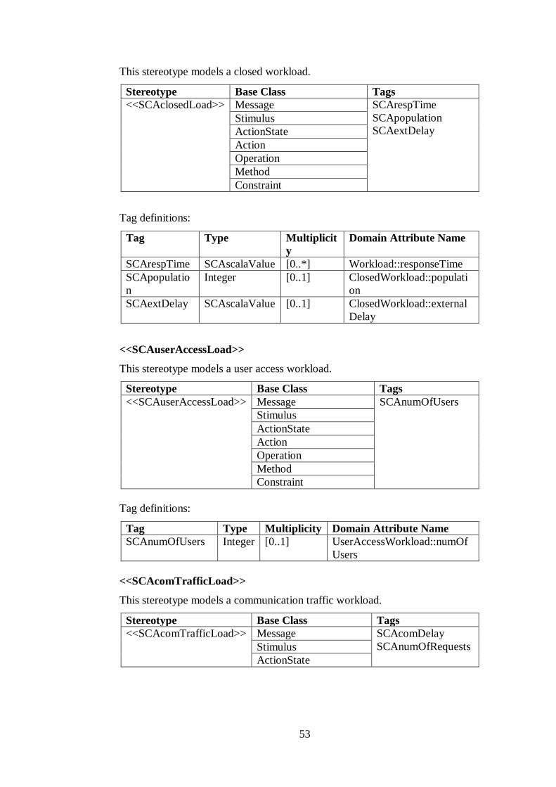
53
This stereotype models a closed workload.
Stereotype Base Class Tags
<<SCAclosedLoad>> Message SCArespTime
SCApopulation
SCAextDelay Stimulus
ActionState
Action
Operation
Method
Constraint
Tag definitions:
Tag Type Multiplicit
y
Domain Attribute Name
SCArespTime SCAscalaValue [0..*] Workload::responseTime
SCApopulatio
n
Integer [0..1] ClosedWorkload::populati
on
SCAextDelay SCAscalaValue [0..1] ClosedWorkload::external
Delay
<<SCAuserAccessLoad>>
This stereotype models a user access workload.
Stereotype Base Class Tags
<<SCAuserAccessLoad>> Message SCAnumOfUsers
Stimulus
ActionState
Action
Operation
Method
Constraint
Tag definitions:
Tag Type Multiplicity Domain Attribute Name
SCAnumOfUsers Integer [0..1] UserAccessWorkload::numOf
Users
<<SCAcomTrafficLoad>>
This stereotype models a communication traffic workload.
Stereotype Base Class Tags
<<SCAcomTrafficLoad>> Message SCAcomDelay
SCAnumOfRequests Stimulus
ActionState

54
Action
Operation
Method
Constraint
Tag definitions:
Tag Type Multiplic
ity
Domain Attribute Name
SCAcomDelay Integ
er
[0..1] CommunicationTrafficWorkload::co
mDelay
SCAnumOfReq
uests
Integ
er
[0..1] CommunicationTrafficWorkload::nu
mOfRequests
<<SCAdbAccessLoad>>
This stereotype models a database access workload.
Stereotype Base Class Tags
<<SCAdbAccessLoad>> Message SCAconUsers
SCAnumOfTransactions Stimulus
ActionState
Action
Operation
Method
Constraint
Tag definitions:
Tag Type Multiplicit
y
Domain Attribute Name
SCAconUser
s
Integ
er
[0..1] StorageAccessWorkload::SCAconUse
rs
SCAnumOfT
ransactions
Integ
er
[0..1] StorageAccessWorkload::numOfTrans
actions
<<SCAstep>>
This stereotype models a step in a scalability analysis scenario.
Stereotype Base Class Tags
<<SCAstep>> Message SCAdemand
SCArespTime
SCAprob
SCArep
SCAdelay
SCAextOp
SCAinterval
Stimulus
ActionState
Action
ActionExecution
Transition

55
Tag definitions:
Tag Type Multiplicity Domain Attribute
Name
SCAdemand SCAscalaValue [0..*] Step::hostExecutionDe
mand
SCArespTime SCAscalaValue [0..*] Step::responseTime
SCAprob Real [0..1] Step::probability
SCArep Integer [0..1] Step::repetition
SCAdelay SCAscalaValue [0..*] Step::delay
SCAextOp SCAextOpValue [0..*] Step::operations
SCAinterval SCAscalaValue [0..*] Step::interval
<<SCAtactic>>
This stereotype models a tactic in a scalability analysis scenario.
Stereotype Base Class Tags
<<SCAtactic>> Message SCAtype
Stimulus
ActionState
Action
ActionExecution
Activity
Tag definitions:
Tag Type Multiplicity Domain Attribute Name
SCAtype String [0..1] Tactic::type
3.4.2.2. Tagged Value Types
The following types of tag value strings are defined for use with the stereotypes
above. In representing the syntax of these types, we use the following standard
BNF notational conventions:
A string between double quotes (“) represents a literal.
A token in angular brackets (<element>) is a non-terminal.
A token enclosed in square brackets ([<element>]) implies an optional
element of an expression.
A token followed by an asterisk (<element>*) implies an open-ended
number of repetitions of that element.

56
A vertical bar indicates a choice of substitutions.
SCAscalaValue
These strings are used to specify a complex performance value. The value is an
array in the following format:
“(“ <source-modifier> “,” <type-modifier> “,” <time-value> “)”.
Source modifier is a string that defines the source of the value meaning
respectively: required, assumed, predicted, and measured:
<source-modifier>::= ‘req’ | ‘assm’ | ‘pred’ | ‘msr’
Type modifier is a specification of the type of value meaning: average, variance,
kth-moment (integer identifies value of k), percentile range (real identifies
percentage value), probability distribution:
<type-modifier> ::= ‘mean’ | ‘sigma’ | ‘kth
-mom’ , <Integer> | ‘max’ |’percentile,’
<real> | ‘dist’.
Time value is a time value described by the SCAtimeValue type.
{SCAduration = (1, ‘sec’)}
For example, the tagged value expression below represents a response time in a
scenario step with a requirement 99% of requests are responded in 500 ms.
{SCArespTime = (‘req’, ‘percentile’, 99, 500, ‘ms’))}
SCAextOpValue
This string is used to identify an external operation. It identifies either the number
of repetitions of that operation that are performed or a scalability time value. The
general format for this string is given as:
“(“ <String> “,” <integer> | <time-value> “)”
RTarrivalPattern
This string is used to specify concrete values of arrival patterns and the details are
described in [42].
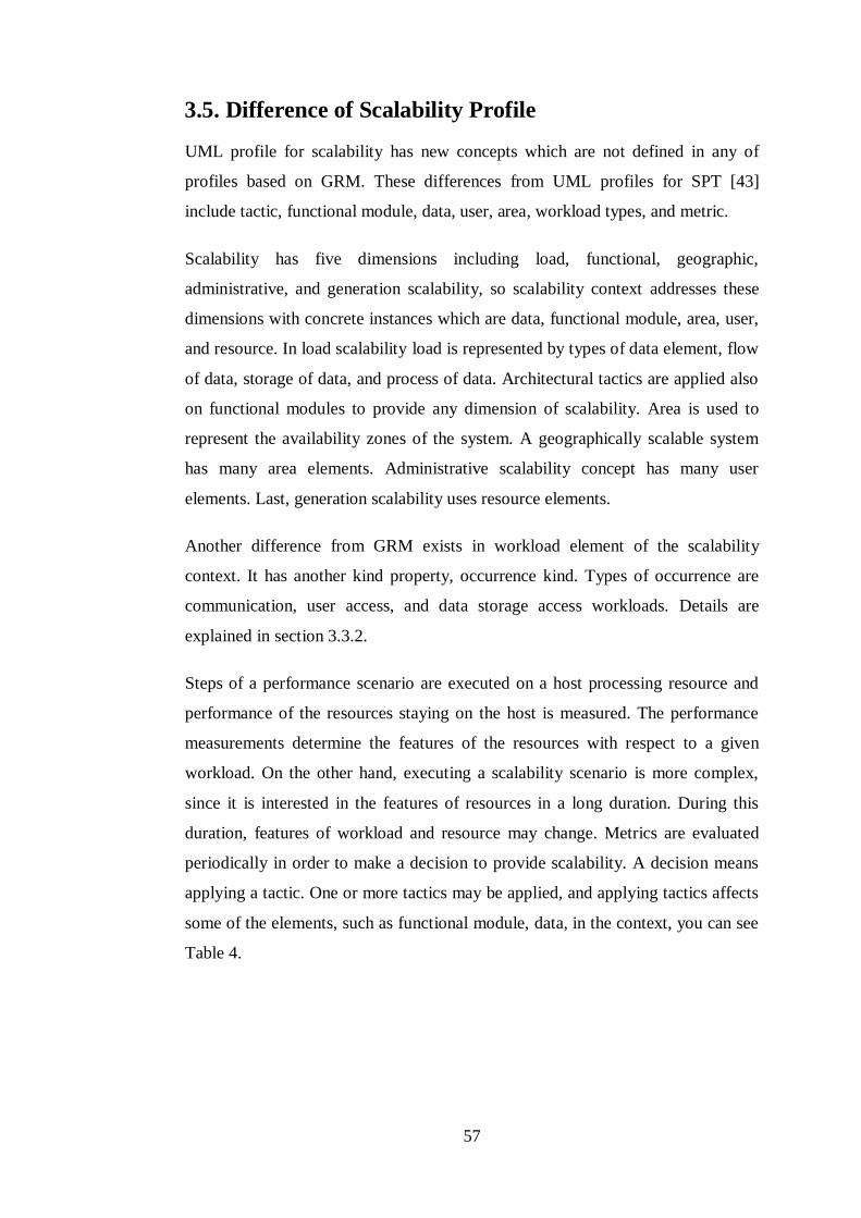
57
3.5. Difference of Scalability Profile
UML profile for scalability has new concepts which are not defined in any of
profiles based on GRM. These differences from UML profiles for SPT [43]
include tactic, functional module, data, user, area, workload types, and metric.
Scalability has five dimensions including load, functional, geographic,
administrative, and generation scalability, so scalability context addresses these
dimensions with concrete instances which are data, functional module, area, user,
and resource. In load scalability load is represented by types of data element, flow
of data, storage of data, and process of data. Architectural tactics are applied also
on functional modules to provide any dimension of scalability. Area is used to
represent the availability zones of the system. A geographically scalable system
has many area elements. Administrative scalability concept has many user
elements. Last, generation scalability uses resource elements.
Another difference from GRM exists in workload element of the scalability
context. It has another kind property, occurrence kind. Types of occurrence are
communication, user access, and data storage access workloads. Details are
explained in section 3.3.2.
Steps of a performance scenario are executed on a host processing resource and
performance of the resources staying on the host is measured. The performance
measurements determine the features of the resources with respect to a given
workload. On the other hand, executing a scalability scenario is more complex,
since it is interested in the features of resources in a long duration. During this
duration, features of workload and resource may change. Metrics are evaluated
periodically in order to make a decision to provide scalability. A decision means
applying a tactic. One or more tactics may be applied, and applying tactics affects
some of the elements, such as functional module, data, in the context, you can see
Table 4.

58
Chapter 4
Software Architecture Perspective
for Scalability
4.1. Definitions
Rozanski and Woods give some crucial definitions about designing the
architecture of a system [47]. They define a view as a representation of one or
more structural aspects of an architecture that illustrates how the architecture
addresses one or more concerns held by one or more of its stakeholders. Also, a
viewpoint is defined as a collection of patterns, templates, and conventions for
constructing one type of a view. They describe a number of perspectives and a
guideline for defining new perspectives in their book. For each perspective in the
catalog they present an outline that describes brief information about that
perspective. The information contains the following properties:
Desired quality gives the definition of the perspective
The perspective’s applicability to views examines the views that are
impacted by the application of the perspective
The most significant concerns the perspective takes care of
An explanation of activities for applying the perspective to the architecture
The architectural tactics present possible solutions in case of the
architecture does not shows its required quality properties the perspective
addresses
Some problems and pitfalls to be aware of and risk-reduction techniques
to prevent these possibly

59
Checklist of things to consider when applying and reviewing the
perspective to help ensure correctness, completeness, and accuracy
Furthermore, in the applicability to views section they examine six core
viewpoints, functional, information, concurrency, development, deployment, and
operational viewpoint.
Functional viewpoint describes the system’s functional elements, their
responsibilities, interfaces, and primary interactions.
Information viewpoint describes the way that the architecture stores,
manipulates, manages, and distributes information.
Concurrency viewpoint describes the concurrency structure of the system
and maps functional elements to concurrency units to clearly identify the
parts of the system that can execute concurrently.
Development viewpoint describes the architecture that supports the
software development process.
Deployment viewpoint describes the environment into which the system
will be deployed.
Operational viewpoint describes how the system will be operated,
administrated, and supported when it is running in its production
environment.
4.2. Scalability Perspective
One of the perspectives in the Rozanski and Woods’ perspective catalog [47] is
performance and scalability. However, although performance and scalability is
associated, scalability is not limited to only performance. Thus, we need to define
a new perspective that is scalability alone. We present scalability perspective in
Table 7 based on the guideline.
Table 7: Brief Description of Scalability Perspective
Desired
Quality
The ability of a system to handle a growing amount of work and to be
adjustable to accommodate that growth
Applicability Any systems that have the possibility of increase in the amount of work;
systems always require low response time; systems that needs additional resources in the future; systems with complex, unclear, or ambitious
scalability requirements
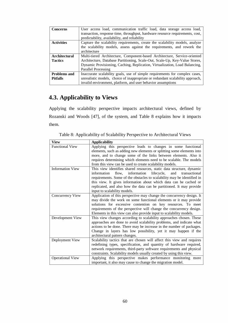
60
Concerns User access load, communication traffic load, data storage access load,
transaction, response time, throughput, hardware resource requirements, cost,
predictability, availability, and reliability
Activities Capture the scalability requirements, create the scalability models, analyze
the scalability models, assess against the requirements, and rework the
architecture
Architectural
Tactics
Multi-tiered Architecture, Component-based Architecture, Service-oriented
Architecture, Database Partitioning, Scale-Out, Scale-Up, Key-Value Stores,
Dynamic Provisioning, Caching, Replication, Virtualization, Load Balancing,
Parallel Processing
Problems and
Pitfalls
Inaccurate scalability goals, use of simple requirements for complex cases,
unrealistic models, choice of inappropriate or redundant scalability approach, invalid environment, platform, and user behavior assumptions
4.3. Applicability to Views
Applying the scalability perspective impacts architectural views, defined by
Rozanski and Woods [47], of the system, and Table 8 explains how it impacts
them.
Table 8: Applicability of Scalability Perspective to Architectural Views
View Applicability
Functional View Applying this perspective leads to changes in some functional
elements, such as adding new elements or splitting some elements into
more, and to change some of the links between elements. Also it
requires determining which elements need to be scalable. The models from this view can be used to create scalability models.
Information View This view identifies shared resources, static data structure, dynamic
information flow, information lifecycle, and transactional
requirements. Some of the obstacles to scalability may be identified in
this view. It gives information about which data can be cached or
replicated, and also how the data can be partitioned. It may provide
input to scalability models.
Concurrency View Application of this perspective may change the concurrency design. It
may divide the work on some functional elements or it may provide
solutions for excessive contention on key resources. To meet
requirements of the perspective will change the concurrency design.
Elements in this view can also provide input to scalability models.
Development View This view changes according to scalability approaches chosen. These
approaches are done to avoid scalability problems, and indicate what actions to be done. There may be increase in the number of packages.
Change in layers has low possibility, yet it may happen if the
architectural pattern changes.
Deployment View Scalability tactics that are chosen will affect this view and requires
redefining types, specification, and quantity of hardware required,
network requirements, third-party software requirements and physical
constraints. Scalability models usually created by using this view.
Operational View Applying this perspective makes performance monitoring more
important, it also may cause to change the migration model.

61
4.4. Concerns
In last decades, most of the system needs to be capable to scale up or scale out.
This need of scalability has some indicators that are used in the evaluation of
system scalability. Meanwhile, since system scalability is dependent on the
system performance, many published papers discussed these two issues together.
However, scalability perspective has other concerns. The concerns of the
scalability perspective describe what the main scalability measures are. The main
concerns are user access load, communication traffic load, data storage access
load, transactions, response time, throughput, hardware resource requirements,
cost, peak load behavior, predictability, availability, and reliability [47], [24].
User Access Load: This indicates the number of concurrent users who access the
system, number of online users, in a given time unit [24]. Concurrent connection
determines the ability of connection to server from various locations at the same
time. Each system has a limit of concurrent connections that specify the total
number of device that can be connect to the server at the same time for a region.
To address more users and to handle more workload in a time period, system
should support concurrency as many as possible. User access load affects the
communication traffic load of the servers and load on data storage access. The
system should accommodate the growing user load in scalable systems.
Communication Traffic Load: It indicates amount of incoming and outgoing
communication messages and transactions in a given time unit [24]. Request per
second, hits per second, and transaction per second describes the communication
traffic load on the servers.
Data Storage Access Load: It refers to the underlying system data store access
load, such as the number of data store access, and data storage sizing [24].
Transactions: A transaction is a unit of work, typically encapsulating a number
of operations, such as reading or writing an object, over a database. Every
database transaction obeys the ACID rules. Transactions should be executed
concurrently in a controlled manner to meet scalability requirements.
62
Response Time: Response time is the duration of a process between starting time,
when a system takes an input, and the ending time, when the system finishes and
reacts to the given input [47]. Response time is formed with service time and wait
time. Service time varies as the workload changes, in other words it tends to
increase as the workload increases. Wait time is the duration the request waits in a
queue. It depends on the number of requests, service time of each request, and the
scheduling algorithm of the system. For scalable systems there should be no high
variations in the value of response time and always be available in its supported
time period. Thus, varying workload should affect the response time as low as
possible.
Throughput: Throughput is the amount of workload the system can handle in a
unit time period [47]. In other words, as the system can finish a task more quickly,
we can say the throughput becomes high. For scalable systems there should be no
high variations in the value of throughput.
Hardware Resource Requirements: Hardware resource requirements have high
impact on the scalability of the system, since how much workload the system can
handle, how fast the system responds to requests, and how many devices
connected it can support depends on the hardware resources of the system [47].
These requirements determine number, type, location of the resources, and the
connection between them.
Cost: The deployment of the system takes important place in scalability of the
system. However, when determining hardware resource requirements
organizations should also think the cost of these resources. Generally, the more
and better hardware resources bring higher throughput and better response times,
yet higher costs. Since the important thing is to be able to satisfy the needs of
stakeholders, they should try to get best configuration that can be afforded in low
cost as possible as.
Predictability: Predictability is the degree to which a correct prediction of a
system’s state can be made either qualitatively or quantitatively [47]. Scalability

63
focuses also predictability of the system’s performance, since it must ensure that
as the workload increases, it must satisfy scalability goals at the present time and
in the future.
Availability: Availability is one of the several important non-functional
requirements related to scalability. It is the capability of providing the intended
service of the system fully or partly [47]. An available system should effectively
handle failures and maintain its operation. A scalable system must be highly
available during a certain period. However, increasing load of a system makes it
difficult.
Reliability: Reliability is the probability of failure or availability [47]. It plays a
key role in cost-effectiveness of a system. A scalable system is expected to be
highly reliable. A potential overload of the system due to limited scalability harms
reliability.
4.5. Activities for Applying Scalability Perspective
The activity diagram in Figure 15 displays the process for applying the scalability
perspective. In this section, we describe the activities in this process.
Figure 15: Applying the Scalability Perspective
4.5.1. Capture Scalability Requirements
To be able meet the scalability goals of a system the only way is to specify each
of them clearly and unambiguously. And they should be determined accurately at
the earliest phase of the system development [16]. Defining them early provides
you with a certain amount of flexibility in the future. The scalability of the system
is also strongly dependent on the performance requirements, so performance
requirements should be stated well before scalability requirements. It is a simple

64
fact that if scalability is not a stated criterion of the system requirements, then the
system designers will generally not consider scalability issues. While loose or
incorrectly defined scalability specifications can lead to failures and
dissatisfaction of users. Moreover, if they stated after the system is deployed,
raising the level of the service to accommodate growth can be difficult and too
costly. However, defining scalability requirements is usually difficult, since it
involves quantitative goals and it is based on future needs. These goals and needs
are determined according to certain amount of estimations, assumptions, and
constraints. Another difficulty is that scalability requirements need more domain
and deployment research, since each system has its own features decided
according to stakeholders’ needs. To be able to provide adequate inputs for
architectural design and analysis, scalability requirements need to be specified
accurately and precisely, and need to be testable. Moreover, as the amount of
workload increases the scalability requirements should be re-examined and
updated.
To be able to capture scalability requirements we follow existing requirements
engineering techniques defined in the IEEE Software Engineering Book of
Knowledge (SWEBOK) [26]. It defines four stages for requirements that are
Elicitation, Analysis, Specification, and Validation. However, these techniques
contribute little concrete support [16]. User stories and use-case-based approaches
to requirements engineering overlook scalability concerns and other nonfunctional
requirements altogether. In the papers [16], [17] authors present a systematic
method for elaborating and analyzing scalability requirements and apply the rules
of GORE (goal-oriented requirements engineering). To specify scalability
requirements they follow the following steps:
i. Specifying Scaling Assumptions
ii. Specifying Scalability Goals
iii. Identifying Scalability Obstacles
iv. Assessing Scalability Obstacles
v. Resolving Scalability Obstacles

65
To reveal scalability goals the following must be clearly specified [47], [17]:
Workload,
Response Time,
Throughput,
And Hardware Resource Requirements.
Specify Workload Requirements: Description of workload goals should include
user access load, communication traffic load, and data storage access load with
the deployment information. When specifying workload, all relevant details
should be covered. These details include number of users and what each of them
is doing, and all of other operations such as management requests, backups, and
error scenarios/handling. Once all loads have been considered, infrequent or
inappropriate workloads can be eliminated. Furthermore, peak workload, a rare or
unexpected increase in the workload, should be defined separately. Because it is
an extreme scenario, the worst case of failure should be thought while defining it.
Meanwhile, specifying the workload provides to detect and processing overload to
ensure flood control mechanisms are in place to avoid the system crashing under
intensive loads. Moreover, when defining workload requirements, researching
past growth patterns of the system can help determine how demand on your
system may grow. The expectation for the quantity of new users within the next
few years, growth rate over the next few years in terms of data, users, and client
applications should also be thought. If you already have a system that runs, then
you should also specify whether there is an anticipated increase in entry volume
and any new business processes are expected.
Specify Response Time Requirements: Response time goals should described
with the information how much workload the system has, measurement location,
and features of hardware resources during that time [47]. User access load,
communication traffic load, data storage access load, and deployment features
affect the response time. As these loads increase response time a user see
increases as well. Also, the location of response time measurement is done should
be specified. For instance, response time measurement that is done from a location
being distant from the servers comes out higher than a location near data center

66
because of network. Furthermore, features of hardware resources should be stated,
since response time is directly proportional to the power of deployment. Response
time is not only concern of scalability and performance perspectives, but also a
concern of usability perspective. According to J. Nielsen’s book [36][39] on
usability response times must be less than 1 second for navigation to feel seamless
and less than 10 seconds to prevent a user’s attention from wandering. These time
limits are caused by the human brain’s structure and are thus firm and stable
decade by decade. Finally, to be more accurate the acceptable error rate allowed
during the measurement of the response times should be defined. Some systems
may produce errors under high workloads and therefore the acceptable error rate
need to be defined.
Specify Throughput Requirements: Scalability requirements should state how
many requests or transactions of each kind processed and go through the system
per unit time as throughput [45]. It should be determined for the steady cases
when the number of incoming requests would be equal to the number of processed
requests. Also, it should be determined for homogenous tasks when a system
doing the same type of business operations for a given time. Its specification is
more difficult for systems with complex workloads; the ratio of different types of
requests can change with the time and season. Moreover, it should be defined for
a specific time and workload, since it varies with time and workload. For instance,
the throughput of a system during typical hour and during peak hour cannot be the
same. Furthermore, the hardware configuration of the system should be specified
while specifying it, since the hardware configuration is also affects it too.
Specify Hardware Resource Requirements: Features and quantities of CPU,
memory, storage, I/O, network, etc. of the system should be specified [45]. We
benefit from these requirements during capacity management, production
monitoring, and resource utilization. The capability of these hardware resources
and cost of them should be considered well before specifying. According to
administrator’s budget, a hardware plan can be made. For instance, they can
purchase hardware at regular intervals to add to their existing deployment. If they

67
have budget limitations, they can purchase servers that can be enhanced later by
adding RAM or CPUs.
4.5.2. Create Scalability Model
A scalable system has a lot of detailed requirements as we examined in the
previous section. Project includes large numbers of stakeholders, high complexity
of interaction between components, multiple persistence mechanisms, multiple
hardware platforms, distribution of components over several hardware platforms,
and high concurrency [25]. Thus, dealing with such a complexity can be a
challenge for every stakeholder. The scalability requirements should be used in an
effective way to facilitate this problem and make it understandable and
manageable. The solution is to create scalability models that provide a set of
measures to make stakeholders assess the workload, concurrency by looking
through useful estimates for capacity planning, and provides [47]. Scalability
models are derived from the viewpoint models of the system. To indicate
scalability critical elements deployment view of the system should be used.
Scalability requirements should be mapped to this view, and features of elements,
such as process, network links, data storages, that need to be scalable, should
display its scalability data. As an example for scalability data we can say the
processing time of functional elements, the request latency between processes,
duration of a database operation, the number of concurrent requests that each
element can handle.
4.5.3. Analyze Scalability
Scalability analysis is about determining the rate at which a system can perform
its action when demands increase or decrease. As other quality requirements of
software, scalability analysis can be carried out two different levels, either
analysis at the architecture design level or analysis at the code level with respect
to the defined requirements. In the first case, by using architecture design as an
input we can measure the impact of predefined scenarios on it, so that we can

68
detect conflicts in the requirements and incomplete design descriptions from a
particular stakeholder’s perspective [15]. This helps to predict the quality of the
system before it is built, thereby reducing unnecessary maintenance costs.
However, not all parameters/metrics can be evaluated at the architecture design
level because of the run-time properties. These metrics need to be analyzed on a
running code.
4.5.3.1. Analysis at Architecture Design Level
Software development consists of phases and initial output of this process is the
architecture design. Architecture design has impact on the subsequent analysis,
design, and implementation phases [52]. Architecture design should satisfy the
software qualities determined by the various stakeholders. To be able to provide
this the fundamental concerns for architecture design should be identified. To
verify that right concerns have been identified usually architecture design are
analyzed or a set of architecture analysis methods are adopted. According to The
Software Architecture Review and Assessment (SARA) report [40] the
architecture evaluation approaches are useful in making design decisions explicit
and supporting the refactoring of the architecture to enhance its quality.
We can apply one or set of the architecture analysis approaches that have been
proposed so far, such as the scenario-based architecture analysis method (SAAM),
the architecture trade-off analysis method (ATAM), scenario-based architecture
reengineering (SBAR), architecture level prediction of software maintenance
(ALPSM), and a software architecture evaluation model (SAEM). A
comprehensive overview of these architecture analysis methods is given in [15].
SAAM can be considered as a mature method which has been validated in various
cases studies, such as [15], [52], among the architecture analysis methods. SAAM
aims to verify basic architectural assumptions and principles against the
requirements and use case scenarios which describe the desired properties of a
software system [31]. Thus, SAAM evaluates the architecture for the given
69
system requirements and architectural description. Also, it analyzes for the risks
by running the scenarios on the architecture.
SAAM uses scenarios. A scenario is a brief description of some anticipated or
desired use of the system [15]. It has two types, direct and indirect scenarios.
Direct scenarios can be directly supported by the architecture. On the other hand,
indirect scenarios require changes in the architecture design and this redesign
needs to be done in order to make them direct scenarios.
4.5.3.2. Analysis at Code Level
The last step of the software development process or phase is about analyzing the
software at code-level. Code analyzing reveals mistakes and potential risks in the
software. Scalability analysis at code level analyzes the behavior of the system at
various load levels, identifies scalability problems and the bottlenecks of the
system. It enables us to verify and validate the quantitative scalability goals and
provides us to examine and to make strong estimations for scalability concerns,
such as response time, throughput, user access load, communication traffic load,
data storage access load. We can also determine availability and reliability
concerns of the software. It measures sufficiency of the underlying hardware
components, so that we can take precautions by making modifications on
deployment before releasing the software system. For analyzing the code in
scalability perspective we can apply one or more of testing methods that involve
performance testing, load testing, endurance testing, stress testing, spike testing,
and scalability testing [36], [51].
Performance testing: Performance testing determines the speed and
stability characteristics of the system under test. It is concerned with
achieving response times, throughput, and resource-utilization levels that
meet the performance objectives for the product.
Load testing: The aim of load testing is to examine how the software
system behaves when it is exposed to varying workload during its

70
production operations and to validate the scalability concerns of the
system.
Endurance testing: This test is focused on examining the behavior of the
system during a long period of time while it is subjected to moderate load
and to validate the scalability concerns of the system.
Stress testing: Stress testing is done by pushing the limits, putting into
conditions that are not anticipated, such as high workload, server failure,
limited memory, insufficient disk space, etc., to find the breaking points of
the system, under what conditions it fails, how it fails, and what indicators
can be monitored to warn of an impending failure, during its production
operations and to validate the scalability concerns of the system.
Spike Testing: Spike testing is used to examine the behavior of the system
while it is subjected to repeatedly increasing workload during a short
period of time and to observe how well an application responds to sudden
increases in the workload that exceeds the anticipated limits.
Scalability testing: Scalability testing is carried out to examine how an
application scales to handle increased load (i.e. serve more users) with
added resources. Scalability tests can be implemented by running one or
more of the above types of performance test against setups with differing
resources and comparing the results. If a significant increase in application
performance and/or capacity is observed, as a result of adding to available
resources, then the system is said to scale well.

71
4.5.4. Assess Against Requirements
Requirements are specified, but they are written on estimations mostly. There is a
need to validate and to verify these requirements. This is done by two ways, either
by conducting practical testing and then checking requirements against test results
or comparing with independent sources. In scalability analysis phase we realize
the first step of the requirement validation. In the second step, after analyzing the
software system in terms of scalability perspective, we should compare the results
of the analysis with the scalability requirements and determine the differences on
these requirements if there exist any. If most of them match, then it means
requirements are valid. If there are cases that don’t match, then modifications on
requirements should be done to correct them. After all comparison and
modifications are done, we should also review all of the scalability requirements
and consider any potential scalability risks.
4.5.5. Rework Architecture
We have validated and verified scalability requirements and analysis results.
Therefore, as a last step it’s time to update the architecture of the system
according to latest version of scalability requirements. We should start with the
functional and the deployment viewpoints, since they are usually the most
affected ones, and then continue updating with the rest of the viewpoints. While
reworking the architecture we can benefit from the architectural tactics described
below. Finally, when we have the modified, improved architecture, we should
also modify our scalability model and repeat the steps we have followed until we
have a stable, with desired quality architecture and system.

72
4.6. Problems and Pitfalls
In this section, we provide the potential scalability problems and pitfalls as well as
the risk-reduction techniques.
4.6.1. Incomplete Scalability Goals
Incomplete or unambiguous scalability goals lead to failures in system scalability
[16], [17], and [47]. If system designers use indefinite scalability goals, they do
not think possible scalability problems and do not take precautions for them.
Risk Reduction:
While defining scalability requirements, make you sure that they are
testable, measurable.
Always validate and verify the scalability requirements by comparing with
another reliable, independent source or by results of tests performed by
you.
4.6.2. Unrealistic Models
Scalability models should cover all of the requirements as well as their details
[44], [47]. A model is an abstraction of reality, so having a lack of feature in the
model yields a system that may encounter a scalability problem in the future.
Besides, scalability models should be realistic.
Risk Reduction:
Always validate and verify the scalability requirements by comparing with
another reliable, independent source or by results of tests performed by
you.
4.6.3. Use of Simple Measures for Complex Cases
While determining scalability requirements, we make estimations to specify the
values of loads, latencies, and hardware features [16], [17], and [47]. Making
wrong estimations is very possible, since the systems are complex and scalability
is affected from various variables, so thinking all of them together is very hard.
Since realizing a system is a long process, firstly we make estimations even they

73
are wrong. However, these values estimated should not be far from its value that it
is required to satisfy scalability. We should make estimations as strong as
possible. Also, scalability testing should be done in a way that every detail should
be thought and specified. If the test does not cover the realistic runtime
environment, then the values that we compare with our estimations will probably
be wrong. As a result, oversimplifying scalability goals and testing leads to wrong
realizations of the system.
Risk Reduction:
Consistently validate and verify your scalability goals.
Consistently compare your testing with independent sources.
Consider the differences between the test environment and the real system
runtime environment to notice critical conflicts.
4.6.4. Inappropriate Partitioning
Partitioning is required when one or more elements involved in nearly all of the
transactions in the system, since it prevents them from being bottlenecks of the
system that violate scalability feature [2], [47]. Separations of concerns,
distributing the tasks, and concurrent execution usually provide more scalability.
However, these separation and distribution, partitioning, should be done
appropriately according to some logic. Otherwise, it would result in a system with
more scalable problems.
Risk Reduction:
Consistently watch for functional elements that have high coupling to most
of the other elements and avoid them from being the bottleneck of the
system.
4.6.5. Invalid Environment and Platform Assumptions
Scalability of the software system is highly dependent on its execution
environments and platforms [45], [47]. Hardware and software the system is
deployed on should be determined according to scalability goals desired. Also,
scalability testing should be done at the environments that are used in realistic
runtime environment. Wrong environment assumptions may occur when you
74
overestimate or underestimate your scalability goals or estimate for an unknown,
new technology. These invalid assumptions lead to scalability problems.
Risk Reduction:
Always validate and verify the scalability requirements by comparing with
another reliable, independent source or by results of tests performed by
you.
4.6.6. Concurrency-Related Contention
Systems usually have concurrency, and processing occurs in separate threads [45],
[47]. However, these threads may work on some shared resources which cause
allocation problems. A shared resource can be used for only read purpose at the
same time by different threads. If a write task requires for a shared resource, then
that resource can only be used by just one thread. This allocation process may be
the bottleneck of the system, since while a shared resource is allocated by one
thread; other threads wait until that resource become free. This situation may
cause serious performance and scalability problems.
Risk Reduction:
Examine your functional, information, and concurrency views to identify
the functional elements that must work concurrently and to identify shared
resources.
Work on your concurrency view to adjust allocation of shared resources
and wait time of threads in a sensible manner.
Also consider other ways that provide threads to access the shared
resources, such as partitioning, replication, caching, etc.
During software development test the concurrent behavior of critical
elements as early as possible and be sure that they will not become
bottlenecks.
4.6.7. Careless Allocation of Resources
Since we can obtain more computing power and more space via better hardware,
we may be careless for allocation of resources. However, our unconsciousness, an
75
excessive allocation and freeing of runtime resources, leads to performance and
scalability problems [45], [47].
Risk Reduction:
Do not allocate and deallocate large amounts of dynamic resource in
critical path elements.
Try to allocate resources in advance and at less critical times, such as
startup or during quiet periods.
Choose the one that requires less effort consumption, between reuse of the
allocated resource or freeing and reallocating them.
Understand the problem thoroughly and document guidelines and patterns.
4.6.8. Disregard for Network and In-Process Invocation
Differences
Most of the systems are distributed and provide the distribution of the resources
over different geographical locations [46], [47]. However, while choosing these
locations, we need to be careful, since accessing a resource on the network
introduces latency and higher response times.
Risk Reduction:
Ensure that the geographical locations of the resources provide less latency
and reflect their inter-element invocation costs in your scalability model.

76
4.6.9. Checklist
In this section, we provide checklists in Table 9 for requirements capture and
architecture definition to consider when applying and reviewing the perspective to
help make sure correctness, completeness, and accuracy. While deciding on the
checklist items, we have benefit from various resources, such as [17], [23], [45],
and [47]. The [CH1] - [CH8] presents the checklist for requirements and the
[CH9] - [CH20] presents the checklist for architecture definition.
Table 9: Checklist Table
Item Explanation
[CH1] Have you identified scalability goals with stakeholders?
[CH2] Have you identified the platform features of the system?
[CH3] Are scalability goals driven by business needs?
[CH4] Does cost of your hardware requirements conform to your project budget plan?
[CH5] Have you considered goals for user access load, communication traffic load,
data access load, response time, and throughput?
[CH6] Have you assessed your scalability goals for reasonableness?
[CH7] Have you appropriately set expectations among your stakeholders of what is
feasible in your architecture?
[CH8] Have you defined all scalability goals within the context of a particular load on
the system?
[CH9] Have you identified possible scalability obstacles in your architecture?
[CH10] Have you done sufficient analysis and testing to figure out the scalability need of the system?
[CH11] What are the expected and maximum workloads the system can process?
[CH12] Do you define the way how to detect the time when to apply the scalability
solution?
[CH13] Do you know to which components you will apply a scalability tactic?
[CH14] Do you know by which tactics your architecture can be scaled when needed?
[CH15] Have assessed the impact of the scalability solution on functionality and
performance? Is this impact acceptable?
[CH16] Have you reviewed your architecture for possible scalability problems?
[CH17] Have external experts reviewed your scalability design?
[CH18] Have you verified and validated estimations you have made for scalability
goals?
[CH19] Have you updated your scalability requirements after you validated the
scalability goals estimated?
[CH20] Have you applied the results of the scalability perspective to all of the affected
views?
77
Chapter 5
Case Study
5.1. Background
Scalability has always been one of the major requirements in designing SaaS
applications to meet the both growing and fluctuating demands. Since these
fluctuating demands may occur at varying frequencies, such as hourly, daily,
weekly, if the SaaS is not well-designed then it may be unresponsive or
inconsistent during a high load. It causes loss in the number of customers and loss
of time and monetary for the designers. To be able to examine this issue we have
followed scalability perspective guideline described in previous sections on a
SaaS application. This part presents our case study, cloud optimized SaaS
framework for enterprise applications using RDBMS.
Cloud Optimized SaaS framework [11] uses the tables and the relations in a given
RDBMS and automatically produces client interfaces. These interfaces provide
listing, editing, and reporting data for the cross-platform devices. Its production
occurs with the usage of a code-base that resides on cloud servers. The aim of this
framework is to develop enterprise applications rapidly and platform independent.
It is used in ERP systems, hotel and property management systems. In our case
study we examine Cloud Hotel Management System (CHMS) that uses the SaaS
framework [10]. This management system manages and tracks all operations
related with different hotel departments. Since most of the hotels serve during
only summer season, three months, they can rent the hotel management software
service for only summer season instead of buying and keeping it for nine months
unnecessarily. As we described above, to meet growing and fluctuating user load,

78
and to achieve a well-designed SaaS, the system must be scalable. Major
requirements of the system are as follows.
Multiple guests connect to CHMS via a travel agency or a hotel or a hotel web site
or online travel agencies simultaneously. Some guests try to book, some of them
download their invoices, and others generate reports. Also, hotel manager see
details about their customers and search for a particular customer. All of these
transactions are done real-time synchronized. As a result, the system should
always be responsive, available, consistent, and scalable. For instance, all of the
stakeholders should see the same condition for the reservation status of a
particular room at the same time. When multiple transactions done by multiple
guests exist on the server, the system may become out of service or some guests
may experience performance issues unless the system is scalable. Scalable
CHMS provides the stakeholders to guarantee access the system always, without
any performance degradation, and without any failures.
5.2. Views
This section explains the application of scalability perspective to the views for our
case study, which allows us to ensure that the architecture is suitable in terms of
scalability perspective. Table 10 lists a summary of the application of scalability
perspective to the views for our case study.
Table 10: Scalability Perspective Application for the Case Study
View Applicability to the case study
Functional Sessionless authorization has been applied. Field validations have
been moved from database layer to client business logic layer. Data to
be displayed in web view has been cached on the client device.
Information We could see that hotel, guest, and other information related with
them may cause a scalability problem, since with multi-tenancy
number of their records is high. Also, we could understand reservation
data is sensitive in terms of consistency and availability, so that we
have taken care of that during applying scalability tactics.
Concurrency No change has been made.
Development Layers have been reorganized. Database has been separated from the
server layer and as a result, the system has client, application, and database layers.
Deployment Application layer and database has been placed on the same Amazon
EC2 server machine. Database has been moved to another EC2

79
instance. Instead of using shared memory TCP/IP will be started to use
to access database. Memory cache will be added in front of the
database, the contents of the application will be reproduced, and a load
balancer will be put in front of them.
Operational Performance monitoring and management has been started and metrics
related to concerns have been collected and tracked periodically. It has
seen that auto scaling can be needed and can be applied in the future.
5.2.1. Functional Viewpoint
CHMS is web-based hotel management software that automates the major hotel
operations. Major stakeholders of it are guests, hotel managers, travel agencies.
The system consists of nine subsystems that are Reservation and Booking, Room,
POS, Guest, Accounting, Agency, Channel, General, and Report Management.
Reservation and Booking Management module keeps track of reservations and.
Room Management module is responsible from the operations related to hotel
rooms, such as room availability, room schema, room status, room wakening list,
and other activities. POS Management module manages the product selling and
delivery operations made by the guests that stays in a hotel or visits for a day.
Guest Management module keeps track of the information about guests that stays
in a hotel or visits for a day. Accounting Management module manages all of the
accounting operations that are done in a hotel. Agency Management module
manages all the information about travel agencies and all of the sales information.
Channel Management module keeps track of selling channels and administrators
that a hotel is contracted out. General Management module is responsible from
room settings, financial settings, etc. Finally, Report Management module
manages generation of various types of reports.
Functional view of CHMS is shown in Figure 16. Database layer contains tables
and stored procedures. SaaS framework automatically extracts the database
schema and generates JavaScript business object model (JBOM) code files that
indicate tables, relations, constraints, stored procedures in JavaScript Object
Notation (JSON) format. They are used in client interface as business logic. Client
interface includes HTML5 UI components, such as forms, views, grids, and
reports that are displayed in web view. Client communication manager manages
client requests and server responses.

80
In the application layer, four components, authorization, multi-tenant filtration,
logging, and data transfer components exist. Authorization component is
responsible from authorization of client requests, such as create, read, update,
delete, and execute. We have chose session authorization, since it has less usage
of computational power, reduces the response time of each request and makes
both component and the system more scalable. We have explained the details in
the section 5.4.3. As a future action when the scale-out is applied on application
instances and a load balancer is added in front of them, the request can be spread
to these instances, so more scalability can be achieved.
Multi-tenant filtration component process each query and eliminates the data that
are not related to tenant of the requested client. Data transfer handles database
operations that come from authorization component. Logging component keeps
record of some events occurred in the application layer and saves these logs into
database.
StoredProcedure
Table
JBOM
DataSet
Grid
Form
Reporting
DataTransfer
Logging
MultiTenantFilter
Authorization
extractViewrequest
response
fetch
save
Figure 16: Functional View of CHMS
5.2.2. Information Viewpoint
With the help of information view we can see which data may cause a scalability
problem, and also we can understand which data is sensitive in terms of
consistency and availability so that we take care on during applying scalability
tactics. For instance, in CHMS reservation information is significant, and it must
be consistent and available during execution. Depending on the room availability
and channel used the reservation can be waited, approved, checked-in, and finally
checked-out. Also, number of hotels, guests, and the information related with

81
them has large number of occurrence in requests, so scalability perspective should
focus on them. All of the components that process the reservation information
should be scalable too.
The system has different type of data transfers between clients and server. This
data are auto-generated client code, client requests, server responses, and also data
transfer between application unit and database. Initially, all of the tables and
relations between them in the database are scanned and code is generated
automatically by the SaaS framework accordingly. This generated code is sent to
a client to be displayed in the interfaces. A request is sent to the server from a
client. This request is either to send information to the server or to get information
from the server. Another flow is logging of records that is; application unit saves
some process results into database.
5.2.3. Concurrency Viewpoint
Application layer of CHMS has dependency on .NET 3.5, Windows Server 2012
r2, and IIS 7 and it uses default values of their configurations. Thus, they handle
the web requests concurrently, and they open thread per request, and limit of
concurrent requests are dependent on them. According to official Windows Server
site [27] default value of maximum number of concurrent ASP requests that are
allowed into the request queue is 3000 and default value of the maximum number
of worker threads per processor that ASP can create is 25. Besides, in database
layer MS SQL Server 2000 queues related queries for consistency of information.
As a result, they continue to use the same environment and same configurations,
and also no change in concurrency design of the application is made after
applying scalability perspective.
5.2.4. Development Viewpoint
CHMS has two separate development views for client-side and server-side. Figure
17 represents the development view of both server-side and client-side of CHMS.
For server-side it has four layers, domain, utility, platform and data layers.
Domain layer consists of nine modules related to management of subsystems,

82
such as Reservation and Booking, Room, POS, Guest, Accounting, Agency,
Channel, General, and Report Management. Utility layer includes logging library,
authorization controls, multi-tenant filtration, security controls, database access,
and message handling library. Platform layer involves .NET 3.5 libraries. Data
layer has tables and stored procedures stored in MSSQL2000 RDBMS.
On the client-side, the system has three-layered architecture that has presentation,
business, and data access layers. Presentation layer contains HTML forms, views,
grids, graphics, and reports. Business layer contains JavaScript files. Data access
layer has datasets that are taken from database and cached in the client device.
Figure 17: Development View of CHMS
As seen in left side of Figure 18, client layer makes requests to application layer,
and application layer processes these requests, fetches data from database layer,
and replies with the result data to client layer.
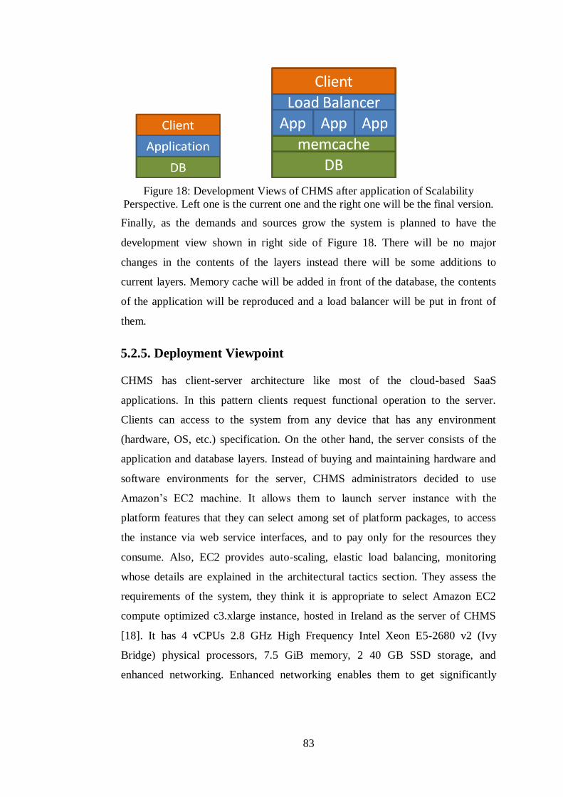
83
Figure 18: Development Views of CHMS after application of Scalability
Perspective. Left one is the current one and the right one will be the final version.
Finally, as the demands and sources grow the system is planned to have the
development view shown in right side of Figure 18. There will be no major
changes in the contents of the layers instead there will be some additions to
current layers. Memory cache will be added in front of the database, the contents
of the application will be reproduced and a load balancer will be put in front of
them.
5.2.5. Deployment Viewpoint
CHMS has client-server architecture like most of the cloud-based SaaS
applications. In this pattern clients request functional operation to the server.
Clients can access to the system from any device that has any environment
(hardware, OS, etc.) specification. On the other hand, the server consists of the
application and database layers. Instead of buying and maintaining hardware and
software environments for the server, CHMS administrators decided to use
Amazon’s EC2 machine. It allows them to launch server instance with the
platform features that they can select among set of platform packages, to access
the instance via web service interfaces, and to pay only for the resources they
consume. Also, EC2 provides auto-scaling, elastic load balancing, monitoring
whose details are explained in the architectural tactics section. They assess the
requirements of the system, they think it is appropriate to select Amazon EC2
compute optimized c3.xlarge instance, hosted in Ireland as the server of CHMS
[18]. It has 4 vCPUs 2.8 GHz High Frequency Intel Xeon E5-2680 v2 (Ivy
Bridge) physical processors, 7.5 GiB memory, 2 40 GB SSD storage, and
enhanced networking. Enhanced networking enables them to get significantly

84
higher packet per second (PPS) performance and lower latencies. Moreover,
since most of the CHMS customers are in Europe region, they select the nearest
location, Ireland, among Amazon’s hosting locations for the server instance.
Choosing the nearest location decreases latencies in the network that has an
impact on the scalability too. Furthermore, the OS is Windows Server 2012 r2,
and it has MSSQL2000 DBMS. The server has IIS 7 and .NET 3.5 software
dependencies.
Figure 19 shows the deployment diagram of current CHMS. The diagram can be
used to identify scalability modules. SCL stereotype is used to tag scalability
modules. Amazon EC2 server and business logic in the client device consists of
application of scalability tactics which are described in tactics section. Scalability
plan of this framework includes maintaining the system scalability for one server
machine and multi-client environment in the first place.
Internet
ApplicationServer
Authorization
Management
Logging
DataTransfer
ClientMachine
WebView
DataSetForms
DatabaseInstance
RDBMS
Figure 19: The deployment structure of CHMS
The one server contains both database and application components. Database
contains multi-tenant data, a lot of information related to a large number of hotels,
and millions of users that is registered to system. Also it contains not only data of
hotel domain, but also data of other domains like property, hospital, etc. Such a
large number of entries and such a large number of clients connected to database
periodically cause a lot of requests and an overload on the server. To solve that
scalability problem they will need to separate the RDBMS from the one server,
and have execution of application and database on separate server machines. Also,
when application layer and database are on the same machine, application layer
accesses to database through shared memory, since it provides performance

85
optimization. However, when they separate them, using TCP/IP protocol is
preferred. Moreover, as the number of clients increase and demands grow they
will start to scale-out, increase the number of application server machines, add
load balancer in front of application servers, add memory cache in front of
database server, etc. And possible outcome of application of these tactics will lead
to a deployment diagram as you see in right side of the Figure 18.
5.2.6. Operational Viewpoint
As we describe in concerns section, response time, throughput, user access load,
communication traffic load, data access load, usage and sufficiency of hardware
resources are crucial for scalability perspective. To be able to collect information
about these concerns and to be able to detect the scalability problems and to
improve the system there is a need to periodic monitoring during the system is
running in its production environment. Since server of CHMS run on the Amazon
EC2 machine, they benefit from CloudWatch to monitor this machine. They
collect and track throughput, processing time, disk usage, and data transfer
metrics, such as number of the requests, latency. They also benefit from MS SQL
Server 2000 counters to assess the volume of workload on database, time taken
for application’s transactions to complete, IIS counters to assess the number of
web requests being serviced and how long it is taking to service them, and
Windows Server 2012 counters to assess the amount of workload that the
application is performing and how long it is taking to perform the operations.
Moreover, by logging component important events and statuses of important
components are written into database. Furthermore, they can also set alarms to be
able to be notified for peak load times. Also, they can use auto scaling feature of
the service to dynamically add or remove EC2 instances by setting an alarm
threshold.
Information stored in database is significant part of the system, and to satisfy
consistency, reliability, and availability of the system a protection of information
is a must. Therefore, information in the database should be backed up
periodically. In CHMS two database backups occur per day. If any failure
86
happens in the database, to rescue information as much as possible they can
restore the last saved information from the backups. This is why two backup
operations occur in a day.
Another important aspect of operational view is maintenance of the system and
user training. User and developer guidelines and APIs are prepared during the
project.
5.3. Applying Scalability Perspective
5.3.1. Scalability Requirements
Scalability requirements of CHMS include limits of user access load,
communication traffic load, data access load, response time, throughput, and also
they specify hardware resource requirements. Initial performance and scalability
system requirements that are determined with customers are extended.
Requirements include mostly quantitative descriptions so that they can be tested
and be verified. These requirements are as follows.
System shall be responsive, available, reliable, and consistent all the time.
95% of all visible pages for customers shall respond in 8 seconds or less,
including infrastructure, excluding back-ends.
The load time for user interface screens shall take no longer than two
seconds.
The log in information shall be verified within five seconds.
System shall response to queries within five seconds.
50 records of any table shall be downloaded at most 1 second. (Max:50kb)
System shall be able to deal with 100 users at the same time.
System shall ensure that performance shall not fall below while supporting
3000 users.
System shall be fast enough to support a 1000-transaction-per-day-
workload.

87
Under a load of 360 update transactions per minute, 95% of transactions
shall return control to the user within 5 seconds of pressing the submit
button.
Under a load of 360 update transactions per minute, 90% of service
requests should return a reply to the calling program within the following
times:
o Open account: 30 seconds
o Update account details: 10 seconds
o Retrieve account status: 5 seconds
o Search operation: 5 seconds
o List operation: 12 seconds
o Filter and sort operations: 7 seconds
o Display graphs, tables, calendars operation: 10 seconds
o Save forms and reports operation: 6 seconds
The DBMS shall support up to 100 concurrent users performing
reservation transactions.
Database of the system shall handle at least a 200 of users at any periods.
Server machine shall have a powerful CPU and high speed internet access
so that it can handle multiple users at the same time.
Server machine shall have higher storage space so that it can have more
user and bigger workspace per user so higher the storage, better the
performance.
Client-side web application shall be developed as a lightweight web app so
that it can work on almost any platform even with slower internet
connections.
System shall handle 2 database backup operations without any
performance degradation per day.
5.3.2. Modeling Guidelines and Examples
In this section we provide application of UML Scalability Profile on Cloud Hotel
Management System (CHMS) that we present in our case study. The deployment
of the logical elements across the engineering environment is shown in Figure 19.
88
Scenario: Scenario is composed of two parts, low-level and high-level scenarios.
Low-level Scenario: The user (us) requests business objects, table, view and
stored-procedure schemes, from the SaaS framework. JBOM files are generated
from RDBMS instance and extracted in the client machine. Client Application
(ca) of CHMS is setup and ready to use. User requests one of web pages that have
a list of records through the Web View (wv) that displays the web page. Then,
user makes an update request and that request comes to program manager (pm) in
the application instance. It, firstly, waits the result of authorization, the
authorization component (ac) checks the credentials, session information by
retrieving id and password from database (db) and comparing them with the data
come. Any result of authorization is sent to logging component (lg). Logging
component inserts the log record into database (db). At the same time, if the
credentials are valid, program manager (pm) starts the processing operation. The
result of the operation is sent through data transfer (dt) component to the client
machine and the Web View (wv) displays the result data. The activity diagram in
Figure 20 depicts this scenario.

89
dt: DataTransfer
lg: Loggingau: Authorizationpm: ProgramManager
db: RDBMSwv: WebView
showForm
sendRequest
handleRequest
checkCredentials
retrieveUserData
processRequest
updatesaveRecord
insert
sendResponse
formResponse
displayResponse
Figure 20: User request low-level scenario – activity diagram representation
High-Level Scenario: In high-level scenario there are a lot of users (us) that
access to the CHMS from their client applications. All of the requests that are
formed by these users are goes through communication links (cm) and reaches to
the CHMS application server (as). Application servers make necessary operations
that require also making database operations in the database instance (db). The
low-level scenario explains the details of these requests and operations during the
usage of one user. It can be thought as a sub-scenario that is occurred many times
in this scenario. After the first iteration is realized, the number of users increases
and the second iteration occurs. And to address demands of many users, the
system is scaled vertically. Finally, the third iteration occurs. This scenario is
represented by the sequence diagram in Figure 21.

90
loop
ca: ClientApp cm: Communication
sendRequest
as: ApplicationServer
handleRequest
db: Database
makeDBOperation
sendDBResponse
sendResponse
displayResponse
Figure 21: User requests high-level scenario – sequence diagram representation
Scalability Requirements
To analyze scalability, we need quantitative information on the execution of the
components. We have the following values labeled as to whether they are
measured values, estimates, or assumptions:
(estimate) System shall ensure that performance shall not fall below while
supporting 3000 users.
(estimate) application instance processing duration: mean: 250 ms
(estimate) database instance processing duration: mean: 150 ms
(estimate) The DBMS support for concurrent users performing some
transactions: 100
(measured) Download duration per record of any table: 12 ms
(assumed) network delay distribution: exponential with mean: 2 ms
Additional parameters that are needed to complete an evaluation include the
requirements, and a description of the workload intensity. Here, we will use the
following additional parameters:
initially the number of users active in the system: $NUsers, a variable
external delay: each user has an average delay between ending one session
and beginning another of 20 minutes
records in a table: $N, a variable
(requirement) Response time for any web page: 95% value < 8000 ms
(requirement) Loading time for any web page: 99% value < 2000 ms

91
(requirement) Verification duration of credentials in authorization
component: 99% value < 5000 ms
The Annotated UML Model
The UML diagrams of CHMS can be annotated with scalability requirements
defined. For example, events and actions of the low-level scenario in activity
diagram shown above are associated with the scalability attributes and the
resulting model is shown in Figure 22. It shows possible response times for
critical operations.

92
dt: DataTransfer
lg: Loggingdb: RDBMSau: Authorization
pm: Management
wv: WebView
<<SCAcontext>>
<<SCAstep>> showForm
<<SCAstep>>sendRequest
<<SCAstep>>handleRequest
<<SCAstep>>checkCredentials
<<SCAstep>>retrieveUserData
<<SCAstep>>processRequest
<<SCAstep>>update
<<SCAstep>>saveRecord
<<SCAstep>>İnsert
<<SCAstep>>formResponse
<<SCAstep>>sendResponse
<<SCAstep>>displayResponse
«SCAopenWorkload»{SCApopulation=$NUsers, SCAextDelay=('mean', 'asgn', 20, 'ms')}
{SCArespTime=('req', 'percentile', 99, 500, 'ms')}
{SCAdemand=('est', 'mean', 250, ms)}
{SCArep=$N,SCAdemand=('est', 'mean', 150, ms),SCAextOp=('record', 12)}
{SCArespTime=('req', 'percentile', 99, 2000, 'ms')}
{SCArespTime=('req', 'percentile', 95, 8000, 'ms')}
Figure 22: User request low-level scenario – activity diagram representation with
scalability annotations
Also, events and actions of the high-level scenario in sequence diagram shown
above are associated with the scalability attributes, see Figure 23. It shows the
impact of increase on number of users and the scale-up tactic. The impacts can be
recognized by comparing the user access loads and the scalability metrics of the
server resource. The values are assumed, so they may not be the same in the real
scenario.

93
loop
loop
loop
ca: ClientApp
<<SCAcontext>>
cm: Communication
sendRequest
as: ApplicationServer
handleRequest
db: Database
makeDBOperation
sendDBResponse
sendResponse
displayResponse
«SCAuserAccessLoad»{SCAnumOfUsers=$NUsers}
«SCAcomTrafficLoad»{SCAcomDelay=('assm', 'mean', 2, 'ms')}
«SCAresource»{SCAcapacity=$C, SCArespTime=$R, SCAutilization=$U,SCAthroughput= $T}
increase
sendRequest
handleRequest
makeDBOperation
sendDBResponse
sendResponse
displayResponse
«SCAtactic» scale-up
sendRequest
handleRequest
makeDBOperation
sendDBResponse
sendResponse
displayResponse
«SCAuserAccessLoad»{SCAnumOfUsers=$2NUsers}
«SCAresource»{SCAcapacity=$C, SCArespTime=$2R, SCAutilization=$2U,SCAthroughput= $T/2}
«SCAresource»{SCAcapacity=$2C, SCArespTime=$R, SCAutilization=$U,SCAthroughput= $T}
Figure 23: User request high-level scenario – sequence diagram representation
with scalability annotations
Finally, we also present the annotated deployment diagram in Figure 24. We have
annotations for the communication traffic, user access, and database access loads.

94
Internet
<<SCAcontext>>
«SCAuserAccesLoad»{SCAconUsers=('est', 'mean', 3000)}
«SCAdbAccessLoad»{SCAconUsers=('est', 'mean', 100)}
«SCAhost»ApplicationServer
«SCAfunctional»Authorization
«SCAfunctional»Management
«SCAfunctional»Logging
«SCAfunctional»DataTransfer
«SCAhost»ClientMachine
«SCAfunctional»WebView
«SCAfunctional»Form
«SCAfunctional»DataSet
«SCAhost»DatabaseInstance
«SCAfunctional»RDBMS
«SCAcomTrafficLoad»{SCAcomDelay=('assm', 'mean', 2, 'ms')}
Figure 24: Annotated deployment model for CHMS
5.4. Architectural Tactics
This section describes the scalability tactics that we have applied. As the demands
and sources grow application, some possible scalability tactics that we will apply
respectively are also listed below. The summary of all of the tactics are shown in
Table 10. It shows which components are affected and in which aspects the tactic
is applied.
5.4.1. Component-based Architecture
As you can see from the development view of CHMS, the system is divided into
layers, client, application, and database. All of the functional elements of the
system are placed in one of these layers, you can see functional view. Also, they
are grouped into modules according to their functional domain to achieve high
cohesion internally and low coupling to the outside. They have minimum
dependency among themselves and do not interfere with each other. This
condition facilitates finding the scalability obstacle and also applying the other
scalability tactics, such as scale-out, load balancing, and replication.
5.4.2. Service-oriented Architecture
Built-in server components of the SaaS framework, such as authorization, multi-
tenant filtration, logging, data transfer, have service behavior and totally they have

95
provided service-oriented architecture. This provides scaling each part of the
application independently. With the application of this pattern asynchrony is also
satisfied, different components of the system can run parallel for concurrent
requests and perform useful work while waiting for input and output to complete.
5.4.3. Minimize the Workload on the Server
CHMS have reduced the workload of the server, in other words it has moved and
distributed some of the operations to clients and it has benefited from the
computational power and memory of clients. Firstly, it has made use of cache part
or all of the data used in a client. After the first fetch of data, it has been placed on
the memory of client. This has provided making most of the operations like
reading, validating, searching, and sorting, on the client-side rapidly without
server connection. Thus, caching has reduced the number and the size of requests
going to the server.
The requests have covered only the atomic create-read-update-delete-execute
(CRUDE) operations that are computed at database. However, holding data has
not been merely adequate. We have needed to move also the business logic, which
processes this information for specific purposes, from server to client layer. For
instance, field validations provide conformity of data to rules, such as minimum
and maximum value or length, while doing operations with data. Before an
operation the system should check whether data is valid or not. When data is not
correct according to validation rules, the system should give an error as an output
and should not continue the operation. Thus, when we have implemented this
operation in client layer, we have made the system more responsive and scalable
by reducing the network traffic and computational operations. Because we have
moved a thing that consumes processing cycle of the whole application to a place
that only one user is affected. Even if these operations must be done at the
application layer, there exists a performance gain, since some of the checks are
eliminated in first check in the client-side.

96
Difference between authorization mechanisms has also some effects on
scalability. There are two ways of authorization, with session or sessionless. With
session authorization client indicates its credentials only in its first request to the
server. In its next requests it indicates its unique session key that is given by the
server if its credentials are correct. Since requests have the session key,
authorization component does not consume computational power for the
validation of credentials On the other hand, in sessionless authorization client
should indicate its credentials in every request to the server. For each request
authorization component validates credentials of the incoming request. In the case
of millions of requests this makes usage of a lot of computational power. As a
result, since session authorization has less usage of computational power, it
reduces the response time of each request and makes both component and the
system more scalable.
5.4.4. Scale-up
Current hardware and software environment has been explained in the deployment
view section. These features have been determined by thinking possible increase
in demands. Therefore, up to now there has been no need to scale-up the system.
But when a scalability problem, high response time, low throughput occurs the
system can be scaled vertically by adding more and better hardware resources
immediately. This can be done easily by editing the configuration of EC2. Also,
EC2 provides auto-scaling that allows us to automatically scale EC2 capacity up
or down according to conditions they define [18]. In other words, during peak
loads they can increase the number resources to maintain performance, and
decrease during low usage periods to minimize costs.
5.4.5. Scale-out
With the advantage of current multi-tenant architecture of CHMS they can easily
scale the system horizontally. They can have more than one application and
database nodes and tenants can be distributed to these nodes. Currently, scale-out
has not been applied, yet in the future it is planned to be done. Firstly, database
will be moved to another EC2 machine. Since multi-domain multi-tenant system
97
brings high load on the server, a need to reduce the load on the server and to make
it more responsive is obvious. Then, as the number of clients, their data, and their
demands increase another horizontal scaling need will emerge. At this point, they
will add more nodes in the application layer and requests will be processed in
more than one application node. By the way, they can benefit from the auto-
scaling feature of EC2 to realize this via web service. Thus, response time and
throughput is stabilized on the same value ranges.
5.4.6. Caching
As we mention in the section 5.4.3 CHMS has applied caching in the client side to
reduce communication traffic load, data access load, and usage of computational
power of the server. Client does not request data from application layer any more
after it has been requested initially. Also, since data can be fetched from memory
rapidly, all of the information, such as customers, bookings, and invoices, that is
displayed in guest or administrator interface is be searched and sorted quickly.
Another caching can be applied in database layer by adding a memory cache in
front of database. By doing this they can optimize the repeated queries and reduce
data access load.
5.4.7. Replication
As the number of requests increase, CHMS application layer cannot response all
of these requests as fast as before. CHMS needs to catch the increase in the
number of requests increase, so the response time should be lower and throughput
should be higher than before. To realize this, replication, one of the scalability
tactics, can be applied. There are two types of replication in terms of the place the
replication occurs, replicating application or data. Firstly, components in the
application layer or the whole application layer can be stored on multiple server
instances. For instance, authorization component can work on multiple machines
that reside in geographically different places. And each of them can hold session
keys of clients who connect to the system from that region. Thus, workload of
authorization on the application layer can be distributed to multiple machines, so a

98
performance improvement can be satisfied. Or another example, during scale-out
application layer as a whole can be placed in different instances. Thus, the total
workload on the server can be distributed and processed concurrently by each of
the application instances. Therefore, the system achieves a performance gain and
can reply to more number of requests without performance degradation.
The second type of replication is multiplying the part or all of the data and storing
them in multiple locations. The details have been explained in section 2.3.2.10.
Database of CHMS has both shared data and tenant specific data. Shared data,
such as countries, languages, currencies, is common data that contain any specific
information to any of the tenants and can be usable by every tenant. It is usually
used for read purposes. Thus, shared data should be replicated on another database
instance. Tenant data has high usage ratio, since most of the requests coming to
database includes it. Since it is used in write operations, it is not preferred to be
replicated.
Moreover, SaaS framework provides the clients of CHMS to load the application
code and parameters from the replicated file servers. Thus, the contention because
of the JBOM files of each client is reduced.
5.4.8. Load Balancing
To reduce response time and waiting time of tasks they can use load balancing in
CHMS. It can be done in the client layer, front-end load balancing, or in
application layer, back-end load balancing. For front-end load balancer, a client
decides a node to connect among available server nodes. This node can be
selected randomly or via an algorithm. Another application of load balancing
occurs in the application layer. When the application layer is horizontally scaled,
number of application instances is increased and a need of distributing incoming
requests to these instances emerges. In CHMS they can use Elastic Load
Balancing service and automatically distribute incoming requests to multiple
application EC2 instances in the application layer [19].

99
Chapter 6
Related Work Scalability concern has been addressed by distributed systems and web-based
systems for ten years. With vastly usage and proliferation of cloud computing,
scalability has become a crucial quality concern for all of the large-scale systems.
It has been addressed as a quality concern and as a problem of not meeting
growing demands in studies of industrial cases. In these studies developers have
shared their scalability problem and solution. Software architecture design books
and guidelines have mentioned scalability concern in non-functional requirements
and with performance criteria. Besides, some of the architectural patterns touch on
the scalability of the software. However, there has been no study that addresses
the scalability perspective as a standalone architectural perspective guideline that
describes its concerns, activities, tactics, aspects, and problems. Rozanski and
Woods [47] have discussed on the architectural perspectives and they have treated
scalability perspective as a sub-concern of the performance perspective. They
have aimed to avoid unexpected, complex, and expensive problems late in the
system lifecycle. Also, there have been some papers and guidelines on scalability.
For example, in [24] SaaS performance and scalability have been evaluated and
analyzed with proposed graphical models and metrics, but they have not focused
on scalability at the architectural level. In [23] the authors have discussed factors
that have impact on SaaS scalability and some tactics to improve SaaS scalability,
yet they have addressed subset of the factors and tactics. Some of the papers have
described application of one scalability tactic or pattern. In [29] they have applied
component-based scalability, in [60] they have worked on scalable SaaS database
design.

100
OMG has proposed various UML profiles, such as profile for schedulability,
performance and time (SPT) [43] and profile for modeling Quality of Service and
Fault Tolerance (QoS & FT) [42]. SPT profile has enabled the construction of
models that can be used for making quantitative predictions regarding these
characteristics [42]. Performance profile has extended the UML meta-model with
stereotypes, tagged values and constraints, which make it possible to attach
performance annotations, such as resource demands and visit ratios, to a UML
model. It has provided facilities for capturing performance requirements within
the design context, associating performance-related QoS characteristics with
selected elements of the UML model, specifying execution parameters which can
be used by modeling tools to compute predicted performance characteristics, and
presenting performance results computed by modeling tools or found by
measurement. Firstly, it has described a domain model which identifies basic
abstractions used in performance analysis. Then, it has mapped the classes from
domain model to a stereotype that can be applied to a number of UML model
elements, and each class attribute to a tagged value. Finally, it has provided
activity or sequence diagrams with performance annotations that illustrate a
scenario. Scenarios define response paths through the system, and can have QoS
requirements such as response times or throughputs. QoS deals with the set of
non-functional aspects of a system that determines the satisfaction level of its
users, and it may be therefore intended as a multi-attribute resulting from the
combination of basic non-functional attributes such as performance and usability
[42]. Fault Tolerance is a very strictly related attribute that assesses the capability
of a system to deliver continuous and failure-free service.
UML performance profile has been used by lots of existing studies. Petriu and
Shen [44] have defined a model transformation method and they have used UML
performance profile as an input to this method. Their method is based on graph-
grammar and transforms automatically a UML model annotated with performance
information into a Layered Queuing Network (LQN) performance model. Their
reason of choosing UML performance profile is that it is easy to understand and it
provides enough annotations for generating LQN models. They have also applied

101
their method on their case study and have provided a deployment and an activity
diagrams with performance annotations. Bennett and Field [5] have assessed the
effectiveness of their performance engineering methodology using UML SPT
profile with a case study, a mobile telecommunications billing system. They have
reached that their methodology is effective at detecting, quantifying, and locating
performance bottlenecks. Their methodology includes system scenarios and
covers the early phases of development process. In order to assess their
methodology, they have translated scenarios of their case study illustrated with
using SPT profile into the stochastic process algebra FSP and have analyzed them
using existing tools.
Another quality domain, reliability, has been addressed by various authors.
Reliability is a measure of the continuous delivery of correct service. Zarras and
Issarny [59] have proposed a UML profile for modeling and assessing software
reliability. They have identified the main concepts of the reliability domain and
have provided domain viewpoint. They have also presented a tool using their
profile definition. Cortellessa and Pompei [13] have presented an UML extension
to be able to model reliability of component-based systems. Their extensions have
built on concepts introduced in SPT profile [42] and have contributed to QoS &
FT profile [42]. They have defined domain model, stereotypes, tags, and
constraints that are related to reliability of component-based systems. Their model
has described the failure rates of components and combines them to obtain a
reliability factor for the whole system. As an example they have included UML
models with reliability annotations for an elevator control system.

102
Chapter 7
Conclusion
The need for economical optimization of resources has leaded to emergence of
cloud computing. Software as a Service (SaaS), the most mature the cloud service
model, addresses the software demands of users. In this model providers own,
host, and manage software at a central site. They offer the same instance of an
application to multiple customers, typically in a single-instance multi-tenant
architecture model. On the other hand, users simply access it remotely over the
Internet instead of installing and maintaining software, and managing hardware.
Recently, SaaS is intended to be used by thousands of people simultaneously and
this increase in SaaS adoption makes scalability as one of key characteristics of
SaaS. Scalability is defined as the ability of a system to either handle a growing
amount of work in a capable manner, or to be enlarged to accommodate that
growth [48]. It brings significant challenges for providers in designing and
maintaining SaaS. In order to fulfill this quality, understanding the scalability
features of the system and being aware of existing scalability patterns are crucial.
In this thesis, we have contributed systematic literature review of SaaS scalability,
UML profile for scalability, and software architecture perspective for scalability.
We have conducted a domain analysis study on scalability of SaaS applications.
In this study, we have aimed to provide a guide for new SaaS applications and to
existing SaaS applications to be able to achieve scalability easily by showing the
most common aspects affecting scalability of SaaS and tactics being applied to
make a SaaS scalable determined so far. During this research we have followed
the steps of Kitchenham’s systematic literature review methodology [33]. We
have analyzed the primary studies we have found in search databases, we have
103
filtered some of them according to our exclusion criteria, and finally have
extracted the data needed and have provided the list of aspects and tactics.
Also, we have proposed UML profile for scalability, which has not been proposed
by any study before. OMG has provided a study on UML profiling, but it has
addressed to only three qualities that are schedulability, performance, and time
[43]. Scalability profile is based on the general resource modeling. It enhances the
comprehension of scalability requirements and estimations. It describes how the
scalability will be for a system without actually testing it in real life.
Furthermore, Rozanski and Woods [47] have presented a perspective catalog that
consists of perspectives for most common quality concepts, such as performance,
availability, security, etc. These perspectives consist of patterns for each
viewpoint to be able to achieve the quality in the architecture. Scalability has been
addressed as a concern of the performance quality, but scalability is a separate
quality that has a relation with performance. Therefore, we have provided a
perspective for scalability, so that it supports the design and analysis of scalable
SaaS architectures. It includes a collection of activities and guidelines that require
consideration across a number of the architectural views. It can assist software
architects in designing, analyzing, and communicating the decisions regarding
scalability. We have illustrated the scalability perspective for a real industrial case
study.
During this study we have identified some possible future works. SLR on search
databases can be expanded to extend list of aspects and list of tactics. Also, a
scalability model can be defined and can be offered to OMG to make it formal. If
it is achieved, transformation between UML profile for scalability and scalability
model can be also provided. A new tool, that allows designing UML diagrams
with scalability annotations and automatically generates a scalability model, may
be introduced. DSL for scalability can be proposed. It can use the stereotypes,
tags, and constraints we have provided in UML profile. A tool that takes system
requirements and architect preferences as inputs to produce scalable architecture
can be implemented.

104
Bibliography
[1] B. Adler. Building Scalable Applications in the Cloud: Reference Architecture
& Best Practices, RightScale, 2011.
[2] D. Agrawal, A. El Abbadi, S. Das, and A. J. Elmore. Database Scalability,
Elasticity, and Autonomy in the Cloud, in Proc. of the 16th
International
Conference on Database Systems For Advanced Applications (DASFAA), pp. 2-
15, Springer-Verlag, 22-25 April 2011.
[3] AWS. SaaS on AWS, Amazon, September 2010.
[4] M. A. Babar, L. Zhu, and R. Jeffery. A framework for classifying and
comparing software architecture evaluation methods, in Proc. of Australian
Software Engineering Conference, pp. 309 – 318, 2004.
[5] A. J. Bennett and A. J. Field. Performance Engineering with the UML Profile
for Schedulability, Performance and Time: A Case Study, in Proc. of the IEEE
Computer Society’s 12th
Annual International Symposium on Modeling, Analysis,
and Simulation of Computer and Telecommunications Systems (MASCOTS),
2004.
[6] S. Bobrowski. The Force.com Multi Tenant Architecture,
https://developer.salesforce.com/page/Multi_Tenant_Architecture. Accessed on
06.11.2014.
[7] C. Chen, G. Chen, D. Jiang, B. Chin Ooi, H. Tam Vo, S. Wu, and Q. Xu.
Providing Scalable Database Services on the Cloud, in Proc. of the 11th
International Conference on Web Information Systems Engineering (WISE), pp.
1-19, Springer-Verlag, 12-14 Dec. 2010.
[8] F. Chong, G. Carraro, and R. Wolter. Multi-Tenant Data Architecture, MSDN,
June 2006.
[9] P. Clements, F. Bachmann, L. Bass, D. Garlan, J. Ivers, R. Little, R. Nord, J.
Stafford. Documenting Software Architectures: Views and Beyond. First Edition.
Addison-Wesley, October 2002.

105
[10] Cloud Hotel Management System. http://www.cloudhotel.us. Accessed on
17.10.2013.
[11] Cloud Optimized SaaS Framework. http://wiki.torkyazilim.com. Accessed on
17.10.2013.
[12] CloudWatch. http://aws.amazon.com/cloudwatch/. Accessed on 26.09.2014.
[13] V. Cortellessa and A. Pompei. Towards a UML profile for QoS: A
Contribution in the Reliability Domain, in Proc. of the 4th International Workshop
on Software and Performance (WOSP), pp. 197-206, ACM, 2004.
[14] Data Model, http://en.wikipedia.org/wiki/Data_model. Accessed On
04.11.2014.
[15] L. Dobrica & E. Niemela. A survey on software architecture analysis
methods. IEEE Trans. on Software Engineering, Vol. 28, No. 7, pp. 638-654, July
2002.
[16] L. Duboc, E. Letier, and D. S. Rosenblum. Systematic Elaboration of
Scalability, IEEE Transactions on Software Engineering, vol. 39, no. 1, pp. 119–
140, January 2013.
[17] L. Duboc, E. Letier, D. S. Rosenblum, and T. Wicks. A Case Study in
Eliciting Scalability Requirements, in Proc. 16th IEEE International Requirements
Engineering Conference, pp. 247-252, 8-12 Sept. 2008.
[18] EC2. http://aws.amazon.com/ec2/. Accessed on 26.09.2014.
[19] Elastic Load Balancing. http://aws.amazon.com/elasticloadbalancing/.
Accessed on 26.09.2014.
[20] S. Fang and Q. Tong. A comparison of multi-tenant data storage solutions for
Software-as-a-Service, in Proc. of 6th
International Conference on Computer
Science & Education (ICCSE), IEEE, pp. 95 – 98, 3-5 Aug. 2011.
[21] S. Frischbier and I. Petrov. Aspects of Data-Intensive Cloud Computing,
From Active Data Management to Event-Based Systems and More, Springer-
Verlag, pp. 57-77, 2010.

106
[22] B. Gao, W. Hao An, X. Sun, Z. Hu Wang, L. Fan, C. Jie Guo, W. Sun. A
Non-intrusive Multi-tenant Database for Large Scale SaaS Applications, in Proc.
8th IEEE International Conference on e-Business Engineering, 2011.
[23] J. Gao, X. Bai, W. Tsai, Y. Huang. Scalable Architectures for SaaS, in Proc.
IEEE 15th International Symposium on Object/Component/Service-Oriented Real-
Time Distributed Computing Workshops, 2012.
[24] J. Gao, P. Pattabhiraman, X. Bai, W. T. Tsai. SaaS Performance and
Scalability Evaluation in Clouds, in Proc. of the 6th
IEEE International
Symposium on Service Oriented System Engineering (SOSE), pp. 61-71, 2011.
[25] J. Garland and R. Anthony. Large Scale Software Architecture, New York,
Wiley, 2003.
[26] IEEE. Guide to the Software Engineering Body of Knowledge (SWEBOK),
IEEE, 2004.
[27] IIS 7, ASP Settings. http://technet.microsoft.com/en-
us/library/cc730855(v=ws.10).aspx. Accessed on 26.09.2014.
[28] L. Jiang, J. Cao, P. Li, and Q. Zhu. A Mixed Multi-tenancy Data Model and
Its Migration Approach for the SaaS Application, in Proc. of IEEE Asia-Pacific
Services Computing Conference (APSCC), pp. 295 – 300, 6-8 Dec. 2012.
[29] S. Kachele and F. J. Hauck. Component-based Scalability for Cloud
Applications, in Proc. of the 3rd International Workshop on Cloud Data and
Platforms (CloudDP), pp. 19-24, ACM, 2013.
[30] M. Kapuruge, J. Han, A. Colman, and I. Kumara. ROAD4SaaS: Scalable
Business Service-Based SaaS Applications. Advanced Information Systems
Engineering (CAISE), pp. 338-352, 2013.
[31] R. Kazman, G. Abowd, L. Bass & P. Clements. Scenario-Based Analysis of
Software Architecture, in Proc. IEEE Software, pp. 47-55, November 1996.
[32] I. Khan. Distributed caching on the Path to Scalability, MSDN Magazine,
July 2009.
107
[33] B. A. Kitchenham. Guidelines for Performing Systematic Literature Reviews
in Software Engineering, Keele Univ. and Univ. Durham, UK, EBSE Tech. Rep.
EBSE-2007-01, Ver. 2.3, Jul. 2007.
[34] R. Krebs, A. Wert, and S. Kounev. Multi-tenancy Performance Benchmark
for Web Application Platforms, in Proc. 13th International Conference on
Web Engineering (ICWE), pp 424-438, Springer-Verlag, 8-12 July 2013.
[35] S. Lehrig. Architectural Templates Engineering Scalable SaaS Applications
Based on Architectural Styles, in Proc. Doctoral Symposium at the 16th
International Conference on Model Driven Engineering Languages and Systems
(MODELS), IEEE, 2013.
[36] J. D. Meier, C. Farre, P. Bansode, S. Barber, D. Rea. Performance Testing
Guidance for Web Applications, Microsoft Corporation, 2007.
[37] P. Mell and T. Grance. The National Institute of Standards and Technology
(NIST) Definition of Cloud Computing, Special Publication 800-145, September
2011.
[38] M. Mosley. DMBOK Functional Framework v3, The Data Management
Association (DAMA) International, The Premier Organization for Data
Professionals Worldwide, September 10, 2008.
[39] J. Nielsen. Designing Web Usability: The Practice of Simplicity. New Riders
Publishing, 1999.
[40] H. Obbink, P. Kruchten, W. Kozaczynski, H. Postema, A. Ran, L. Dominick,
R. Kazman, R. Hilliard, W. Tracz, E. Kahane. Software Architecture Review and
Assessment (SARA) Report. February, 2002.
[41] Object Management Group. Unified Modeling Language Specification v.
2.4.1, OMG document number formal/2011-08-05.
[42] Object Management Group. UML Profile for Modeling Quality of Service
and Fault Tolerance Characteristics and Mechanisms. Request for Proposal,
ad/02-01-07, January 2002.
108
[43] Object Management Group. UML Profile for Schedulability, Performance
and Time Specification. OMG Document, Version 1.1, formal/05-01-02, January
2005.
[44] D. C. Petriu, H. Shen. Applying the UML Performance Profile: Graph
Grammar-Based Derivation of LQN Models from UML Specifications, TOOLS
'02 Proceedings of the 12th International Conference on Computer Performance
Evaluation, Modeling Techniques and Tools, pp. 159-177, Springer-Verlag, 2002.
[45] A. Podelko. Multiple Dimensions of Performance Requirements, in Proc.
33rd International Computer Measurement Group (CMG) Conference, 2-7
December 2007.
[46] M. Reza Rahimi, N. Venkatasubramanian, S. Mehrotra, and A. V. Vasilakos.
MAPCloud-Mobile Applications on Elastic and Scalable 2-Tier Cloud
Architecture, in Proc. IEEE 5th International Conference on Utility and Cloud
Computing (UCC), pp. 83 - 90, 5-8 Nov. 2012.
[47] N. Rozanski, E. Woods, Software Architecture Systems Working with
Stakeholders Using Viewpoints and Perspectives, First Edition, Addison-Wesley,
April 2005
[48] Scalability, http://en.wikipedia.org/wiki/Scalability. Accessed On
04.11.2013.
[49] J. Song, Z. Yan, F. Han, Y. Bao, and Z. Zhu. Introducing SaaS Capabilities
to Existing Web-Based Applications Automatically, in Proc. 14th Asia-Pacific
Web Conference (APWeb), Web Technologies and Applications, pp 560-569,
Springer-Verlag, 11-13 April 2012.
[50] C. Spence, J. Devoys, S. Chahal. Architecting Software as a Service for the
Enterprise, Cloud Computing, Intel Information Technology, October 2009.
[51] B. M. Subraya. Integrated Approach to Web Performance Testing, IRM
Press, 2006.
[52] B. Tekinerdoğan. ASAAM: Aspectual Software Architecture Analysis
Method, in Proc. of 4th Working IEEE/IFIP Conference on Software Architecture
(WICSA), pp. 5-14, June 2004.
109
[53] B. Tekinerdoğan, K. Öztürk, and A. Doğru. Modeling and Reasoning about
Design Alternatives of Software as a Service Architectures, in Proc. Architecting
Cloud Computing Applications and Systems workshop, 9th Working IEEE/IFIP
Conference on Software Architecture, pp. 312-319, 20-24 June 2011.
[54] W. Tsai, Q. Shao, Y. Huang, X. Bai. Towards a Scalable and Robust Multi-
tenancy SaaS, in Proc. Second Asia-Pacific Symposium on Internetware ACM,
2010.
[55] W. Tsai, X. Sun, Q. Shao, and G. Qi. Two-Tier Multi-tenancy Scaling and
Load Balancing, IEEE 7th International Conference on e-Business Engineering
(ICEBE), pp. 484-489, 10-12 Nov. 2010.
[56] W. Wu, W. Tsai, W. Li, B. Esmaeili. Model-driven tenant development for
PaaS-based SaaS, IEEE 4th International Conference on Cloud Computing
Technology and Science (CloudCom), pp. 821 - 826, 3-6 Dec. 2012.
[57] J. Wu, Q. Liang, E. Bertino. Improving Scalability of Software Cloud for
Composite Web Services. IEEE International Conference on Cloud Computing,
2009.
[58] D. Yuanyuan, N. Hong, W. Bingfei, L. Lei. Scaling the Data in Multi-tenant
Business Support System. Pacific-Asia Conference on Knowledge Engineering
and Software Engineering, IEEE, 2009.
[59] A. Zarras and V. Issarny. UML-based Modeling of Software Reliability.
[60] Y. Zhang, S. Liu, X. Meng. Towards high level SaaS maturity model:
Methods and case study, in Proc. Services Computing Conference, IEEE Asia-
Pacific (APSCC), pp. 273-278, 7-11 Dec. 2009.
110
Publications Related to This Thesis
O. Ozcan and B. Tekinerdogan. Architectural Perspective for Design and Analysis
of Scalable Software as a Service Architectures, Managing trade-offs in adaptable
software architectures (MASA), 2015, to be submitted.