analog voice system reference - comtech ef data...• communication interface cards, either digital...
TRANSCRIPT
Analog VoiceNetPerformer® System Reference

COPYRIGHTS AND DISCLAIMERS
Published Date: August 4, 2014
Document # 1603
This publication contains information proprietary and confidential to Memotec Inc. Any reproduction, disclosure or unauthorized use of this publication is expressly prohibited except as Memotec Inc. may otherwise authorize in writing.
Memotec Inc. reserves the right to make changes without notice in product or component design as warranted by evolution in user needs or progress in engineering or manufacturing technology. Changes which affect the operation of the unit will be documented in the next revision of the manual.
We have made every effort to ensure the accuracy of the information presented in our documentation. However, Memotec assumes no responsibility for the accuracy of the information published. Product documentation is subject to change without notice. Changes, if any, will be incorporated in new editions of these documents. Memotec may make improvements or changes in the products or programs described within the documents at any time without notice. Mention of products or services not manufactured or sold by Memotec is for informational purposes only and constitutes neither an endorsement nor a recommendation for such products or services.
Memotec Inc. is a wholly owned subsidiary of Comtech EF Data Corp., and its parent company Comtech Telecommunications Corp (NASDAQ: CMTL).
AccessView, CXTool, CX-U Series, CX-UA Series, AbisXpress, NetPerformer, AccessGate, ACTView, SDM-8400, and the SDM-9000 series of products are either registered trademarks or trademarks of Memotec Inc.in Canada, the United States of America, and in other countries.
Windows is a registered trademark of Microsoft Corporation in the United States and other countries.
Any other trademarks are the property of their respective companies.
Copyright © 2014 Memotec Inc.
Memotec Inc.7755 Henri Bourassa Blvd. WestMontreal, QuebecCanada H4S 1P7Tel.: (514) 738-4781FAX: (514) 738-4436www.memotec.com

Contents
Chapter 1: NetPerformer Support of Analog Voice . . . . . . . . . . . . . . . . . . . . . . . . . . . . . . 1-1
1. 1 Analog Equipment Connections Supported. . . . . . . . . . . . . . . . . . . . . . . . 1-2
1. 2 Signaling Engine Technology and Analog Voice Protocols . . . . . . . . . . . . 1-3
1.2.1 ACELP-CN . . . . . . . . . . . . . . . . . . . . . . . . . . . . . . . . . . . . . . . . . 1-3
1.2.2 PCM . . . . . . . . . . . . . . . . . . . . . . . . . . . . . . . . . . . . . . . . . . . . . . 1-4
1.2.3 Modem Relay . . . . . . . . . . . . . . . . . . . . . . . . . . . . . . . . . . . . . . . 1-4
1. 3 Digital Signal Processor (DSP) Functions . . . . . . . . . . . . . . . . . . . . . . . . . 1-5
1.3.1 ACELP Compression/Decompression Procedure . . . . . . . . . . . 1-5
1.3.2 Fax Demodulation . . . . . . . . . . . . . . . . . . . . . . . . . . . . . . . . . . . 1-6
1.3.3 Variable Bit Rate . . . . . . . . . . . . . . . . . . . . . . . . . . . . . . . . . . . . 1-6
1.3.4 Echo Canceling . . . . . . . . . . . . . . . . . . . . . . . . . . . . . . . . . . . . . 1-7
1.3.5 Custom Signaling . . . . . . . . . . . . . . . . . . . . . . . . . . . . . . . . . . . . 1-7
1. 4 Analog Voice Connections. . . . . . . . . . . . . . . . . . . . . . . . . . . . . . . . . . . . . 1-8
1.4.1 E&M Interface Card . . . . . . . . . . . . . . . . . . . . . . . . . . . . . . . . . . 1-9
1.4.2 Signaling Variations Supported . . . . . . . . . . . . . . . . . . . . . . . . . 1-9
1.4.3 PBX Trunk-Side Connection . . . . . . . . . . . . . . . . . . . . . . . . . . . 1-9
1.4.4 FXS Interface Card . . . . . . . . . . . . . . . . . . . . . . . . . . . . . . . . . 1-10
1.4.5 FXO Interface Card . . . . . . . . . . . . . . . . . . . . . . . . . . . . . . . . . 1-11
1. 5 Tones Generated by the NetPerformer . . . . . . . . . . . . . . . . . . . . . . . . . . 1-13
1. 6 Line Activation Types. . . . . . . . . . . . . . . . . . . . . . . . . . . . . . . . . . . . . . . . 1-14
1.6.1 Predefined Line Activation . . . . . . . . . . . . . . . . . . . . . . . . . . . . 1-14
1.6.2 Switched Line Activation . . . . . . . . . . . . . . . . . . . . . . . . . . . . . 1-15
1.6.3 Autodial Line Activation . . . . . . . . . . . . . . . . . . . . . . . . . . . . . . 1-17
1.6.4 Broadcast Line Activation. . . . . . . . . . . . . . . . . . . . . . . . . . . . . 1-18
1.6.5 Installation Requirements. . . . . . . . . . . . . . . . . . . . . . . . . . . . . 1-19
1.6.6 Operation . . . . . . . . . . . . . . . . . . . . . . . . . . . . . . . . . . . . . . . . . 1-20
1.6.7 Deactivation . . . . . . . . . . . . . . . . . . . . . . . . . . . . . . . . . . . . . . . 1-22
1.6.8 Specialized Line Activation . . . . . . . . . . . . . . . . . . . . . . . . . . . 1-22
1. 7 Supplementary Services on an Analog Interface. . . . . . . . . . . . . . . . . . . 1-23
Chapter 2: Configuring Analog Voice Connections. . . . . . . . . . . . . . . . . . . . . . . . . . . . . . 2-1
2. 1 Configuration Overview . . . . . . . . . . . . . . . . . . . . . . . . . . . . . . . . . . . . . . . 2-2
2. 2 Configuring the Physical Port (LINK) . . . . . . . . . . . . . . . . . . . . . . . . . . . . . 2-3
2.2.1 Configuring an FXS Physical Port (LINK) . . . . . . . . . . . . . . . . . 2-3
2.2.2 Configuring an FXO Physical Port (LINK) . . . . . . . . . . . . . . . . . 2-3
Memotec Inc.

2.2.3 Configuring an E&M Physical Port (LINK) . . . . . . . . . . . . . . . . . 2-4
2. 3 Configuring the Analog Voice Channels (CHANNEL) . . . . . . . . . . . . . . . . 2-5
2. 4 Configuring Supplementary Services . . . . . . . . . . . . . . . . . . . . . . . . . . . . 2-8
2.4.1 Configuring Billing Signals on an FXS Channel. . . . . . . . . . . . . 2-8
2.4.2 Configuring Retransmission of Caller ID over an FXS Interface 2-11
2.4.3 Detection of Caller ID on an FXO Interface . . . . . . . . . . . . . . . 2-12
2. 5 Specialized Analog Voice Applications . . . . . . . . . . . . . . . . . . . . . . . . . . 2-15
2.5.1 Hoot and Holler . . . . . . . . . . . . . . . . . . . . . . . . . . . . . . . . . . . . 2-15
2.5.2 Push To Talk . . . . . . . . . . . . . . . . . . . . . . . . . . . . . . . . . . . . . . 2-15
Chapter 3: Configuring the Voice Mapping Table . . . . . . . . . . . . . . . . . . . . . . . . . . . . . . . 3-1
3. 1 About the Voice Mapping Table . . . . . . . . . . . . . . . . . . . . . . . . . . . . . . . . 3-2
3. 2 Adding a MAP Entry . . . . . . . . . . . . . . . . . . . . . . . . . . . . . . . . . . . . . . . . . 3-3
3. 3 Modifying a MAP Entry . . . . . . . . . . . . . . . . . . . . . . . . . . . . . . . . . . . . . . . 3-6
3. 4 Deleting a MAP Entry . . . . . . . . . . . . . . . . . . . . . . . . . . . . . . . . . . . . . . . . 3-7
3. 5 Uploading or Downloading the MAP File. . . . . . . . . . . . . . . . . . . . . . . . . . 3-8
Chapter 4: Monitoring Analog Voice Connections . . . . . . . . . . . . . . . . . . . . . . . . . . . . . . 4-1
4. 1 About the NetPerformer console command . . . . . . . . . . . . . . . . . . . . . . . 4-2
4.1.1 Display States (DS) . . . . . . . . . . . . . . . . . . . . . . . . . . . . . . . . . . 4-2
4.1.2 Display Channel States (DCS) . . . . . . . . . . . . . . . . . . . . . . . . . 4-3
4.1.3 Display Errors (DE) . . . . . . . . . . . . . . . . . . . . . . . . . . . . . . . . . . 4-4
4.1.4 Display Configuration Parameters (DP). . . . . . . . . . . . . . . . . . . 4-4
Chapter 5: Calling Procedures. . . . . . . . . . . . . . . . . . . . . . . . . . . . . . . . . . . . . . . . . . . . . . . 5-1
5. 1 Initiating a Call. . . . . . . . . . . . . . . . . . . . . . . . . . . . . . . . . . . . . . . . . . . . . . 5-2
5.1.1 Predefined and Autodial Line Activation . . . . . . . . . . . . . . . . . . 5-2
5.1.2 Switched Line Activation . . . . . . . . . . . . . . . . . . . . . . . . . . . . . . 5-2
5. 2 Terminating a Call . . . . . . . . . . . . . . . . . . . . . . . . . . . . . . . . . . . . . . . . . . . 5-6
5.2.1 Predefined and Autodial Line Activation . . . . . . . . . . . . . . . . . . 5-6
5.2.2 Switched Line Activation . . . . . . . . . . . . . . . . . . . . . . . . . . . . . . 5-6
5. 3 Examples of Calling Procedures . . . . . . . . . . . . . . . . . . . . . . . . . . . . . . . . 5-8
5.3.1 FXS-to-FXS Application with Predefined Line Activation. . . . . . 5-8
5.3.2 E&M-to-E&M Application with Voice Switching . . . . . . . . . . . . 5-10
5.3.3 FXS-to-FXS Application with Voice Switching . . . . . . . . . . . . . 5-12
5.3.4 FXO-to-FXS Application for a Specific Extension . . . . . . . . . . 5-14
5.3.5 Fax Application for a Specific Extension . . . . . . . . . . . . . . . . . 5-16
Memotec Inc.

Chapter 6: SE/SLOT/#/LINK Configuration Parameters. . . . . . . . . . . . . . . . . . . . . . . . . . . 6-1
6. 1 Common Parameters. . . . . . . . . . . . . . . . . . . . . . . . . . . . . . . . . . . . . . . . . 6-2
6.1.1 Status . . . . . . . . . . . . . . . . . . . . . . . . . . . . . . . . . . . . . . . . . . . . . 6-2
6.1.2 Pcm encoding law . . . . . . . . . . . . . . . . . . . . . . . . . . . . . . . . . . . 6-2
6. 2 FXS Interface Card . . . . . . . . . . . . . . . . . . . . . . . . . . . . . . . . . . . . . . . . . . 6-3
6.2.1 Billing signal type . . . . . . . . . . . . . . . . . . . . . . . . . . . . . . . . . . . . 6-3
6. 3 E&M Interface Card . . . . . . . . . . . . . . . . . . . . . . . . . . . . . . . . . . . . . . . . . . 6-4
6.3.1 E&M type . . . . . . . . . . . . . . . . . . . . . . . . . . . . . . . . . . . . . . . . . . 6-4
Chapter 7: SE/SLOT/#/CHANNEL Configuration Parameters . . . . . . . . . . . . . . . . . . . . . . 7-1
7. 1 Common Parameters. . . . . . . . . . . . . . . . . . . . . . . . . . . . . . . . . . . . . . . . . 7-2
7.1.1 Protocol . . . . . . . . . . . . . . . . . . . . . . . . . . . . . . . . . . . . . . . . . . . 7-2
7.1.2 ACELP-CN Parameters . . . . . . . . . . . . . . . . . . . . . . . . . . . . . . . 7-3
7.1.3 PCM/ADPCM/G729 Parameters . . . . . . . . . . . . . . . . . . . . . . . . 7-5
7.1.4 Other Parameters Common to All Protocols . . . . . . . . . . . . . . . 7-6
7.1.5 Local outbound voice level (db) . . . . . . . . . . . . . . . . . . . . . . . . . 7-6
7.1.6 Priority Level . . . . . . . . . . . . . . . . . . . . . . . . . . . . . . . . . . . . . . . 7-6
7.1.7 Echo canceler . . . . . . . . . . . . . . . . . . . . . . . . . . . . . . . . . . . . . . 7-7
7.1.8 Double talk threshold (db) . . . . . . . . . . . . . . . . . . . . . . . . . . . . . 7-7
7.1.9 Pulse frequency (pps) . . . . . . . . . . . . . . . . . . . . . . . . . . . . . . . . 7-8
7.1.10 Activation type . . . . . . . . . . . . . . . . . . . . . . . . . . . . . . . . . . . . . . 7-8
7.1.11 PREDEFINED Activation Type Parameters. . . . . . . . . . . . . . . . 7-9
7.1.12 SWITCHED Activation Type Parameters. . . . . . . . . . . . . . . . . 7-10
7.1.13 AUTODIAL Activation Type Parameters . . . . . . . . . . . . . . . . . 7-13
7.1.14 BROADCAST Activation Type Parameters . . . . . . . . . . . . . . . 7-14
7.1.15 Other Parameters Common to All Activation Types. . . . . . . . . 7-15
7. 2 FXS Channel Parameters . . . . . . . . . . . . . . . . . . . . . . . . . . . . . . . . . . . . 7-26
7. 3 FXO Channel Parameters . . . . . . . . . . . . . . . . . . . . . . . . . . . . . . . . . . . . 7-29
7. 4 E&M Channel Parameters . . . . . . . . . . . . . . . . . . . . . . . . . . . . . . . . . . . . 7-32
Chapter 8: SE/MAP Configuration Parameters. . . . . . . . . . . . . . . . . . . . . . . . . . . . . . . . . . 8-1
8. 1 Operation . . . . . . . . . . . . . . . . . . . . . . . . . . . . . . . . . . . . . . . . . . . . . . . . . . 8-2
8. 2 Entry digits . . . . . . . . . . . . . . . . . . . . . . . . . . . . . . . . . . . . . . . . . . . . . . . . . 8-2
8. 3 Destination name. . . . . . . . . . . . . . . . . . . . . . . . . . . . . . . . . . . . . . . . . . . . 8-2
8. 4 Destination extension source. . . . . . . . . . . . . . . . . . . . . . . . . . . . . . . . . . . 8-3
8. 5 Hunt group . . . . . . . . . . . . . . . . . . . . . . . . . . . . . . . . . . . . . . . . . . . . . . . . . 8-4
8. 6 Destination extension . . . . . . . . . . . . . . . . . . . . . . . . . . . . . . . . . . . . . . . . 8-4
Memotec Inc.

8. 7 Extended digits source . . . . . . . . . . . . . . . . . . . . . . . . . . . . . . . . . . . . . . . 8-5
8. 8 Number of user extended digits . . . . . . . . . . . . . . . . . . . . . . . . . . . . . . . . 8-5
8. 9 Extended digits to forward. . . . . . . . . . . . . . . . . . . . . . . . . . . . . . . . . . . . . 8-6
8. 10 Use SVC connection . . . . . . . . . . . . . . . . . . . . . . . . . . . . . . . . . . . . . . . . . 8-6
8. 11 SVC address type . . . . . . . . . . . . . . . . . . . . . . . . . . . . . . . . . . . . . . . . . . . 8-7
8. 12 SVC network address . . . . . . . . . . . . . . . . . . . . . . . . . . . . . . . . . . . . . . . . 8-7
8. 13 Add another map entry . . . . . . . . . . . . . . . . . . . . . . . . . . . . . . . . . . . . . . . 8-8
Index . . . . . . . . . . . . . . . . . . . . . . . . . . . . . . . . . . . . . . . . . . . . . . . . . . . . . . . . . . . . . . . Index-1
Memotec Inc.

1
NetPerformer Support of Analog VoiceMemotec Inc. 1-1

Analog Voice
1.1 Analog Equipment Connections SupportedA NetPerformer can be connected to any of the following using an analog interface:
• PSTN: Using an FXO interface, the NetPerformer offers compatibility with a Public Switched Telephone Network (PSTN)
- The NetPerformer interfaces with the Central Office (CO) like a standard tele-phone set
- It is able to detect a ring and generate off-hook and on-hook signals.
• POTS line: Using an FXS interface, the NetPerformer provides CO connections to standard telephone sets or facsimile machines.
• KTS: A Key Telephone System (KTS) unit is usually connected to multiple ports on the NetPerformer, using FXS interfaces
- The NetPerformer behaves like a CO
- It is able to select an extension and generate a ring.
• PBX: The NetPerformer provides the 2/4-wire E&M interfaces required for tie trunks to analog PBXs.
- E&M channels perform routing functions which offload PBX processing requirements.
- E&M Types I, II and V are supported
- For station-side connection to a PBX an FXO interface is used, since the Net-Performer acts like a standard telephone
NOTE: NetPerformer connection to a digital PBX is accomplished using ISDN sig-naling. For further information, consult the Digital Voice fascicle of this doc-ument series.
1-2 Memotec Inc.
NetPerformer Support of Analog Voice
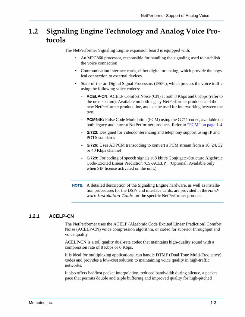
1.2 Signaling Engine Technology and Analog Voice Pro-tocols
The NetPerformer Signaling Engine expansion board is equipped with:
• An MPC860 processor, responsible for handling the signaling used to establish the voice connection
• Communication interface cards, either digital or analog, which provide the phys-ical connection to external devices
• State-of-the-art Digital Signal Processors (DSPs), which process the voice traffic using the following voice codecs:
- ACELP-CN: ACELP Comfort Noise (CN) at both 8 Kbps and 6 Kbps (refer to the next section). Available on both legacy NetPerformer products and the new NetPerformer product line, and can be used for interworking between the two.
- PCM64K: Pulse Code Modulation (PCM) using the G.711 codec, available on both legacy and current NetPerformer products. Refer to “PCM” on page 1-4.
- G.723: Designed for videoconferencing and telephony support using IP and POTS standards
- G.726: Uses ADPCM transcoding to convert a PCM stream from a 16, 24, 32 or 40 Kbps channel
- G.729: For coding of speech signals at 8 kbit/s Conjugate-Structure Algebraic Code-Excited Linear Prediction (CS-ACELP). (Optional: Available only when SIP license activated on the unit.)
NOTE: A detailed description of the Signaling Engine hardware, as well as installa-tion procedures for the DSPs and interface cards, are provided in the Hard-ware Installation Guide for the specific NetPerformer product.
1.2.1 ACELP-CN
The NetPerformer uses the ACELP (Algebraic Code Excited Linear Prediction) Comfort Noise (ACELP-CN) voice compression algorithm, or codec for superior throughput and voice quality.
ACELP-CN is a toll quality dual-rate codec that maintains high-quality sound with a compression rate of 8 Kbps or 6 Kbps.
It is ideal for multiplexing applications, can handle DTMF (Dual Tone Multi-Frequency) codes and provides a low-cost solution to maintaining voice quality in high-traffic networks.
It also offers bad/lost packet interpolation, reduced bandwidth during silence, a packet pace that permits double and triple buffering and improved quality for high-pitched
Memotec Inc. 1-3
Analog Voice
voices.
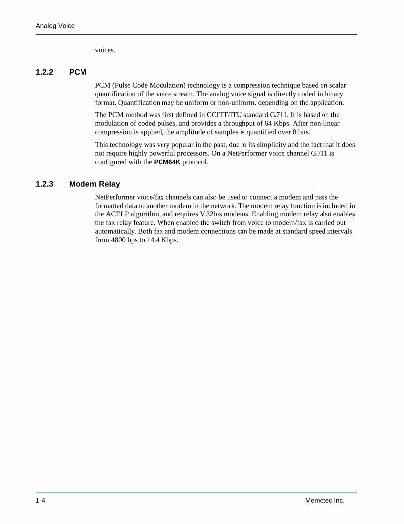
1.2.2 PCM
PCM (Pulse Code Modulation) technology is a compression technique based on scalar quantification of the voice stream. The analog voice signal is directly coded in binary format. Quantification may be uniform or non-uniform, depending on the application.
The PCM method was first defined in CCITT/ITU standard G.711. It is based on the modulation of coded pulses, and provides a throughput of 64 Kbps. After non-linear compression is applied, the amplitude of samples is quantified over 8 bits.
This technology was very popular in the past, due to its simplicity and the fact that it does not require highly powerful processors. On a NetPerformer voice channel G.711 is configured with the PCM64K protocol.
1.2.3 Modem Relay
NetPerformer voice/fax channels can also be used to connect a modem and pass the formatted data to another modem in the network. The modem relay function is included in the ACELP algorithm, and requires V.32bis modems. Enabling modem relay also enables the fax relay feature. When enabled the switch from voice to modem/fax is carried out automatically. Both fax and modem connections can be made at standard speed intervals from 4800 bps to 14.4 Kbps.
1-4 Memotec Inc.

NetPerformer Support of Analog Voice
1.3 Digital Signal Processor (DSP) FunctionsAnalog-to-digital (A/D) conversion must be performed before an analog voice signal can be carried over a digital line. A DSP is a microprocessor designed to digitize and process voice signals. The NetPerformer DSP carries out digitization and compression algorithms while consuming very little bandwidth. It is also used to handle other features of digitized voice processing, such as variable bit rates and echo canceling.
Low-cost implementations of CELP-type compression algorithms in single-chip form became practical with the advent of the most recent generation of high-performance DSPs. The NetPerformer DSP and ACELP codec represent the latest advances in voice compression technology, and together provide very efficient voice compression.
1.3.1 ACELP Compression/Decompression Procedure
• If the voice input is in analog format., the NetPerformer takes this analog source and converts it to a 64 Kbps digital stream in PCM (Pulse Code Modulation) for-mat.
• Using ACELP-CN, for example, the DSP cuts the data into 20 ms cells.
• The DSP then analyzes the voice spectrum and compresses the digital stream to 8 Kbps using the ACELP-CN algorithm. This provides a compression ratio of 8:1.
Figure 1-1: Processing of Voice/Fax Traffic
DSP
Voice Input
Voice Channels
Fax Input
Digital Data Stream
64 Kbps
Compres-sion
Demodu-lation
alternateprocesses
Analog toDigital
Conversion
14.4 Kbpsor lower
Fragmen-tation
Voice andfax traffic
To prioritzationand multiplexingwith data traffic
32 Kbps orlower (typically
8 Kbps)
Cell packets sentto remote sites
- Frame Relay- Dedicated lines
Prioritizationand
Multiplexing
From DSPProcessing
Digitized, compressedvoice and fax cells
LAN/WAN traffic fromother sources
Memotec Inc. 1-5

Analog Voice
• The NetPerformer then combines the compressed voice cells with data from dif-ferent sources according to assigned priorities. By default, voice traffic is defined as high priority, since it is extremely delay-sensitive.
• The mixed traffic is then transmitted over the wide area network using NetPer-former Cell Relay technology.
• At the remote end these processes are reversed. The remote channel’s DSP receives the compressed voice traffic and decompresses it to a 64 Kbps digital PCM stream.
• If the output is analog, the remote NetPerformer reconverts the PCM stream to analog format and sends it to the attached voice equipment.
1.3.2 Fax Demodulation
When a NetPerformer DSP detects a fax tone it stops compressing the voice stream and starts demodulating the fax stream.
• The NetPerformer demodulates the fax signals into HDLC (High-level Data Link Control) data at speeds of 14.4 Kbps or lower.
• The HDLC data is then fragmented into cells.
• The NetPerformer then combines the HDLC/fax cells with data from different sources according to assigned priorities. Fax, which is extremely delay-sensitive, is given high-priority status by default.
• The mixed traffic is then transmitted to remote sites using Cell Relay technology.
• At the remote end these processes are reversed. The remote channel receives the HDLC/fax cells and converts them to digital fax signals.
• The remote NetPerformer then reconverts the digital stream to analog format and sends it to the attached fax equipment.
Since audio transmission signals at 64 Kbps are converted to a digitized stream at 14.4 Kbps or lower, fax demodulation reduces the required bandwidth. Combined with the advantages of fragmentation and cell relay, the result is more efficient transport of fax signals, with reduced delays.
1.3.3 Variable Bit Rate
The NetPerformer’s ACELP-CN compression algorithm produces 8 Kbps or 6 Kbps voice output. However, the NetPerformer can lower the bit rate even further depending on the nature of the voice stream. The speed is automatically reduced to a lower bit rate when:
• Signaling and DTMF tones are transmitted, or
• Silent periods occur. The reduced bandwidth is used to maintain background noise on the line (without some background noise, users perceive the line to be dead).
Voice communication is intrinsically half-duplex by nature: when one person speaks at one end of the line, the person at the other end listens. Pauses may also occur during
1-6 Memotec Inc.

NetPerformer Support of Analog Voice
speech, for example, between sentences, when the speaker leaves the phone, or when the speaker puts the listener on hold. The NetPerformer detects these silence periods. Its variable bit rate takes advantage of the fact that noise and DTMF signaling tones require less bandwidth than the voice traffic itself. It can then allocate the bandwidth saved from a silent or signaling voice channel to channels that are processing voice traffic. The result of a variable bit rate is optimized bandwidth utilization, improved system performance and a reduction of overall network costs.
1.3.4 Echo Canceling
Echo is caused by impedance mismatches on the telephone circuit. It is a distorted and delayed replica of the incoming speech from the remote end.
The NetPerformer has an echo canceler built into its DSP. Should echo occur on a speech or non-speech signal (such as voice-band data or fax) the echo cancelled automatically reduces this echo to tolerable levels. It adapts automatically to changes in the echo that may occur in successive connections along the virtual path. It also minimizes background noise and prevents the negative effects of double talk. Echo cancellation can be enabled or disabled using the Echo Canceler parameter. By default, it is disabled.
1.3.5 Custom Signaling
NetPerformers equipped with a Signaling Engine can be configured for custom signaling and custom ring for analog and digital voice connections. These custom parameters define signaling characteristics used on non-standard equipment. Refer to the chapter Custom Signaling in the Advanced Voice Features fascicle of this document series.
NOTE: If no custom signaling parameters are defined, the NetPerformer will use the standard values associated with the line signaling protocol, determined from the Signaling Type parameter for the voice channel.
Memotec Inc. 1-7

Analog Voice
1.4 Analog Voice ConnectionsA NetPerformer analog port connects to an analog PBX or directly to an analog telephone.
• Analog PBX trunking connections require the use of an E&M interface card
• An FXS interface card is used when connecting to an analog telephone or KTS unit
• An FXO interface card is used when connecting to a CO or a PBX extension.
NOTE: Analog interface cards can be used for voice, fax and modem support only. The voice channel Interface type is configured under software control from the console or through SNMP access. Further information on analog interface cards can be found in the Hardware Installation Guide for your NetPerformer product.
NOTE: A T1 or E1 port on a NetPerformer digital interface card can also connect to an analog telephone or PBX, using Channel Associated Signaling (CAS). For details, refer to the Digital Voice fascicle of this document series.
Figure 1-2: Analog Voice Support on the NetPerformer
Card Signaling Ports per Card Channels per Card
FXS FXS Loop Start 2 or 4 2 analog voice
FXO FXO Loop Start 2 or 4 2 analog voice
E&M IMMEDIATE START, WINK START, CUSTOM
4 4 analog voice
Table 1-1: Analog voice support on analog interface cards
SignalingEngineBoard
ProductBaseboard
E&MInterface
FXSInterface
RS-232 orV.35 Port
PVCR orFrame RelayConnection
PBX withanalog port
1-8 Memotec Inc.
NetPerformer Support of Analog Voice
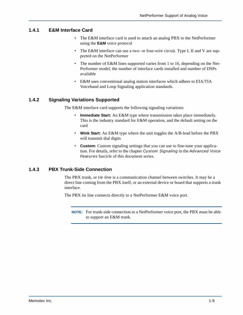
1.4.1 E&M Interface Card
• The E&M interface card is used to attach an analog PBX to the NetPerformer using the E&M voice protocol
• The E&M interface can use a two- or four-wire circuit. Type I, II and V are sup-ported on the NetPerformer
• The number of E&M lines supported varies from 1 to 16, depending on the Net-Performer model, the number of interface cards installed and number of DSPs available
• E&M uses conventional analog station interfaces which adhere to EIA/TIA Voiceband and Loop Signaling application standards.
1.4.2 Signaling Variations Supported
The E&M interface card supports the following signaling variations:
• Immediate Start: An E&M type where transmission takes place immediately. This is the industry standard for E&M operation, and the default setting on the card
• Wink Start: An E&M type where the unit toggles the A/B-lead before the PBX will transmit dial digits
• Custom: Custom signaling settings that you can use to fine-tune your applica-tion. For details, refer to the chapter Custom Signaling in the Advanced Voice Features fascicle of this document series.
1.4.3 PBX Trunk-Side Connection
The PBX trunk, or tie line is a communication channel between switches. It may be a direct line coming from the PBX itself, or an external device or board that supports a trunk interface.
The PBX tie line connects directly to a NetPerformer E&M voice port.
NOTE: For trunk-side connection to a NetPerformer voice port, the PBX must be able to support an E&M trunk.
Memotec Inc. 1-9

Analog Voice
Figure 1-3 demonstrates PBX trunk-side connection to the NetPerformer.
1.4.4 FXS Interface Card
• An FXS interface card connects a telephone or KTS unit directly to the NetPer-former unit, using the FXS voice protocol
• The NetPerformer presents a Telco/PTT interface that acts like a Central Office and can interface to a conventional two-wire telephone (pulse-dial or touch-tone)
• The numbers of FXS connections supported can vary from 1 to 8, depending on the NetPerformer model, the number of interface cards installed and number of DSPs available
• FXS uses the Loop Start Signaling method to seize and sense a line
- Loop Start Signaling uses 2 wires, Tip and Ring, to perform signaling and carry Voice Frequency (VF) signals.
- A relay opens or closes the loop between a particular subscriber and the Net-Performer FXS port. This generates current flow into the loop, which is detected by the switching equipment.
• A NetPerformer FXS port provides loop current and ring voltage, and detects the off-hook and on-hook states.
Figure 1-4 shows an application that uses both FXS and FXO interfaces (see next section)
Figure 1-3: PBX Trunk-Side Connection
E&MTieLine
Trunk Side Station Side
PBX BE&M
Station Side Trunk Side
TieLine
PBX A
Telephones
FaxMachines
Telephones
FaxMachines
Local Unit Remote Unit
1-10 Memotec Inc.

NetPerformer Support of Analog Voice
on the NetPerformer.
1.4.5 FXO Interface Card
• An FXO interface card connects the NetPerformer to a Central Office (CO) or the station side of a PBX, using the FXO voice protocol
• The NetPerformer presents a Telco/PTT interface that acts like a standard tele-phone set
• The numbers of FXO lines supported can vary from 1 to 8, depending on the Net-Performer model, the number of interface cards installed and number of DSPs available
• FXO uses the Loop Start Signaling method to seize and sense a line
The NetPerformer FXO connection simulates a two-wire telephone in a loop-start circuit.
• A NetPerformer FXO port detects ring voltage, closes the loop during off-hook and opens the loop in an on-hook condition.
PBX Station-Side ConnectionA PBX can connect to a NetPerformer voice port from the PBX station side. In this case, the PBX is accessed in the same way as a CO.
When making a station-side connection, configure the NetPerformer voice port with an FXO interface, since the port must act like a standard telephone set (generate on-hook and off-hook, detect a ring, etc.).
Figure 1-5 demonstrates PBX station-side connection to the NetPerformer.
Figure 1-4: NetPerformer FXS and FXO Interfaces
Trunk
RemoteUnit
FXOFXS
LocalUnit
CONetPerformer NetPerformer
Telephone,Facsimile or
KTS Unit
Memotec Inc. 1-11

Analog Voice
Figure 1-5: PBX Station-Side Connection
Station Side Trunk Side
PBX
Telephones
FaxMachines
FXOFXS
Telephoneor KTS Unit
Local Unit Remote Unit
1-12 Memotec Inc.
NetPerformer Support of Analog Voice
1.5 Tones Generated by the NetPerformerThe following tones can be generated by the NetPerformer for analog voice calls:
• Audio tones: Dial tone, ringback tone and busy signals. These are generated according to North American standards. Thus if you make a call from London, you will hear the North American signaling tones, not those for the United King-dom. Busy signals include:
- Slow busy, generated when the destination is busy
- Fast busy, generated when the link goes down
- Incompatibility tone, generated when some fatal problem with the voice con-nection occurs, for example, the voice algorithms are mismatched.
• Physical tone: Remote (equipment) ring on the telephone set, generated from the electrical signal originating from an attached CO. The frequency at which the NetPerformer generates a ring is governed by the global Ring frequency parame-ter, and may be 17, 20, 25 or 50 Hz. Its voltage is governed by the global Ring voltage parameter, and may be 60 or 80 Volts RMS. Refer to the chapter Global Functions in the Quick Configuration fascicle of this document series.
• Multi-frequency tones: These include the DTMF, MF and R2 tones. Their sig-nals are passed transparently when a conversation is in progress. They have no effect at any time for predefined line activation (see next section). For switched line activation, they are intercepted in the early stages of the calling procedure to determine the destination unit and port from the Voice Mapping Table, and are then passed transparently once the call is placed. They can be used for interactive touch tone procedures during a call.
• Billing tones: These tones are used for billing purposes. See “Supplementary Services on an Analog Interface” on page 1-23.
NOTE: The NetPerformer does not generate a Reorder tone or Flash Hook signal.
Memotec Inc. 1-13

Analog Voice
1.6 Line Activation TypesFor full network flexibility, voice/fax line activation can be configured as switched, predefined, autodial or broadcast. Use the Activation type parameter on the voice channel, which can be set as SWITCHED, PREDEFINED, AUTODIAL or BROADCAST. Refer to the chapter “Configuring Analog Voice Connections” on page 2-1.
1.6.1 Predefined Line Activation
For predefined activation, the destination unit and port number are preconfigured by the user. As soon as the device connected to the local port goes off-hook, the local NetPerformer begins the calling procedure with the destination device. In other words, all you have to do is lift the telephone receiver, and the remote telephone will ring immediately. This configuration can be used only when a dedicated telephone is available at both the source and destination sites. Often, a more popular alternative is the autodial connection, discussed later in “Autodial Line Activation” on page 1-17.
To configure a port for predefined line activation, set the voice channel Activation type parameter to PREDEFINED. You will be requested to define the Remote unit and Port number. For testing purposes, you can set up predefined line activation between two ports at the same site. This is a convenient way to test channels locally either before or after the network is in operation.
NOTE: The two voice ports linked through predefined line activation cannot be accessed by any other voice port in the network.
Example of Predefined Line Activation
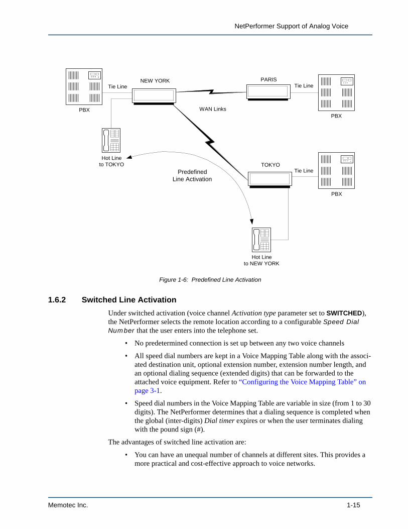
Two large PBXs at different sites can be linked together through predefined line activation. The PBXs control the switching functions and the NetPerformer controls bandwidth usage and the communications line. Predefined line activation can also be used to set up a hot line, for example, between the presidents of two affiliated companies. In Figure 1-6, a hot-line connection has been set up between New York and Tokyo in a network servicing many extensions.
1-14 Memotec Inc.
NetPerformer Support of Analog Voice
1.6.2 Switched Line Activation
Under switched activation (voice channel Activation type parameter set to SWITCHED), the NetPerformer selects the remote location according to a configurable Speed Dial Number that the user enters into the telephone set.
• No predetermined connection is set up between any two voice channels
• All speed dial numbers are kept in a Voice Mapping Table along with the associ-ated destination unit, optional extension number, extension number length, and an optional dialing sequence (extended digits) that can be forwarded to the attached voice equipment. Refer to “Configuring the Voice Mapping Table” on page 3-1.
• Speed dial numbers in the Voice Mapping Table are variable in size (from 1 to 30 digits). The NetPerformer determines that a dialing sequence is completed when the global (inter-digits) Dial timer expires or when the user terminates dialing with the pound sign (#).
The advantages of switched line activation are:
• You can have an unequal number of channels at different sites. This provides a more practical and cost-effective approach to voice networks.
Figure 1-6: Predefined Line Activation
NEW YORK PARIS
TOKYOHot Line
to TOKYO
Hot Lineto NEW YORK
PBXPBX
PBX
Tie LineTie Line
Tie Line
WAN Links
PredefinedLine Activation
Memotec Inc. 1-15

Analog Voice
• Three or more offices can be interconnected without requiring a central PBX or multiple compression/decompression cycles. This method of voice/fax switching reduces delays and requires less bandwidth than for a central PBX setup.
With switched line activation, the NetPerformer base product also supports:
• Local voice switching: Permits a switched voice call from one voice channel to another on the same unit
• Hunt Groups: Permits attempting more than one voice channel when trying to place an ingress call. Details on this feature are provided in the Advanced Voice Features fascicle of this document series.
Example of Switched Line Activation
Figure 1-7 shows how a switched connection can be made from London to either Frankfort or Amsterdam.
• The Frankfort site is defined in London's Voice Mapping Table as having speed dial numbers 11 and 12, and Amsterdam as speed dial numbers 21 and 22.
• The Remote Extension Number Source is set to MAP, which means that the extension numbers will be taken from the Voice Mapping Table and a call con-nect attempt will be made to one port only.
• If a user at the London site dials 11:
- The NetPerformer looks in its Voice Mapping Table and determines that this speed dial number is associated with destination unit Frankfort and extension number 101.
- It attempts to make a connection with Frankfort on the voice channel that has been defined with extension number 101.
- The call is placed if this port is available; otherwise a busy tone is returned to the London unit.
• The same user may dial 22 from London to access Amsterdam, extension 202. As before, the Voice Mapping Table holds all information required for the Net-Performer to place the call.
1-16 Memotec Inc.

NetPerformer Support of Analog Voice
1.6.3 Autodial Line Activation
Under autodial line activation (voice channel Activation type parameter set to AUTODIAL), the NetPerformer behaves like a switch that always dials to the same place. Autodial activation has a blend of switched and predefined features:
• Like switched activation:
- The NetPerformer reaches the remote location using a Speed Dial Number. This number is permanently configured for the voice port, and does not need to be manually entered.
- An extended digits sequence can be either user-dialed (configured with the voice channel definition) or defined in the Voice Mapping Table.
• Like predefined activation:
- The NetPerformer begins the calling procedure with the remote site as soon as the device connected to the voice channel goes off-hook.
Unlike predefined line activation, inward dialing is allowed on a voice port configured for autodial line activation. In other words, an autodial voice channel is accessible from any other NetPerformer voice channel in the network.
Figure 1-7: Switched Line Activation
London Voice Mapping Table
LONDONFRANKFORT
DestinationUnit
Speed DialNumber
FRANKFORTFRANKFORTAMSTERDAMAMSTERDAM
11122122
User dials 11
ExtensionNumber
101102201202
AMSTERDAM
User dials 22
Ext. 101
Ext. 102
Ext. 201
Ext. 202
Call connectattempt
Call connectattempt
Memotec Inc. 1-17

Analog Voice
1.6.4 Broadcast Line Activation
Broadcast line activation of a voice port is most commonly used in applications requiring voice broadcasting over multiple speakers, such as a PA system spanning several locations.
Under broadcast activation (voice channel Activation type parameter set to BROADCAST), the NetPerformer participates in a Frame Relay one-way multicast service. In this setup:
• Voice traffic is transmitted from one end user, called a root, via the multicast server (the Frame Relay switch) to all other users in the multicast group, called leaves.
• Frames are never sent in the opposite direction, that is, from the leaves to the root.
• The multicast service allows a user to send a single message to multiple destina-tions.
• Broadcast transmission is a connection-oriented service, in that a PVC connec-tion must be established to the multicast server before the multicast data can be transmitted.
• In addition, the root must have a direct PVC to all participating leaves.
How It Works • When sending voice traffic to the leaves, the root sends multicast frames over the multicast connection using the multicast DLCI (Mdlci).
• The multicast server accepts these frames and sends them to all of the leaves in the multicast group.
• The frames arrive at the leaves as though they were sent over the direct PVCs configured between the root and the leaves.
- Each leaf receives the multicast frames on the PVC (DLCI) configured for direct connection to the root.
- The Mdlci value is not included in the received frame.
NOTE: Frames sent in a multicast service are delivered to each active member of the group. If a leaf is temporarily unavailable, the frames are not kept for later delivery. The unavailable leaf will not receive frames until it returns to normal operation.
Example In the example in Figure 1-8:
• The NetPerformer unit BOSTON (the root) uses Frame Relay for voice transmis-sions, and has a one-way multicast service for broadcasting voice messages to the remote NetPerformers (the leaves).
1-18 Memotec Inc.

NetPerformer Support of Analog Voice
• The multicast group is logically comprised of the leaf PVCs 1, 3 and 5, which are defined for direct connection to the leaves.
• The one-way multicast service accepts broadcast frames on the Mdlci from BOS-TON and transmits them to each remote unit.
• As these frames travel across the network they are treated like any other frames, and therefore arrive at their destinations as though they had actually been trans-mitted over the root PVCs 1 to 3.
• Thus the unit NEW_YORK receives frames on its PVC 3, CHICAGO on its PVC 5 and LOS_ANGELES on its PVC 1.
1.6.5 Installation Requirements
To set up a Voice Broadcasting network you must:
• Install a special client interface in the PBX (or other user device) connected to the root.
This interface generates an off-hook condition on the line and/or generates a code which the root NetPerformer sends to the Frame Relay switch through a locally initiated connection.
• Install another client interface at each device connected to the leaves.
This interface controls the operation of the speakers at the remote sites.
• On the root NetPerformer, configure a PVCR PVC (PVC mode set to PVCR) for each connection to a leaf.
• In the example in Figure 1-8, PVCs 1, 2 and 3 at the BOSTON site are defined as PVCR PVCs (refer to the WAN/Frame Relay fascicle of this document series).
Figure 1-8: One-way Multicast Voice Broadcasting
PVC 1
Mdlci
Frame RelayNetwork
BOSTON
NEW_YORK
CHICAGO
LOS_ANGELES
Multicastserver
PVC 2
PVC 3
PVC 3
PVC 5
PVC 1
BroadcastPVC
PVCR PVCs
PVCR PVCs
Multicast groupdefined here
Memotec Inc. 1-19
Analog Voice
Since the root is on the transmitter side, the PVC Broadcast group parameter must be set to NO for all of these PVCs.
• On the root NetPerformer, configure a single Broadcast PVC (PVC mode set to BROADCAST) for the connection to the multicast server.
The DLCI you define for this PVC is the Mdlci.
• On the root NetPerformer, configure an analog voice channel with Broadcast line activation (Activation type parameter set to BROADCAST) and set its Broadcast direction parameter to TX.
This voice channel handles the actual data transmission for the PVCs. The PVC number you define for this voice port is the number of the Broadcast PVC.
NOTE: For one-way multicast broadcasting you can define only one transmitter per transmission channel.
• On each leaf NetPerformer, configure a PVCR PVC for connection to the Frame Relay network.
- These are the PVCs that the multicast server will use to send the broadcast frames to the leaves
- Since a leaf is on the receiver side, the PVC Broadcast group parameter must be set to YES, which defines the leaf as a member of the broadcast group.
In the example in Figure 1-8, the PVCs at the NEW_YORK, CHICAGO and LOS_ANGELES sites are defined as PVCR PVCs in a Broadcast Group.
• On each leaf NetPerformer, configure an analog voice channel with Broadcast line activation to handle the actual data transmission between the Frame Relay network and the leaf.
- Since the leaves receive broadcast frames, you must set the Broadcast Direc-tion parameter to RX on each of these voice ports.
- Define the PVC number as the number of the PVCR PVC that is included in the multicast group.
1.6.6 Operation
Voice broadcasting from the root to the leaves is typically activated in the following manner:
• The client interface at the root initiates the transmission by going off-hook
• The root starts to transmit broadcast frames, which activates the leaves.
• A connection is established between the local and remote voice channels
• The client interface at the root may generate a code digit for one second, which passes through the Frame Relay switch to all remote sites
1-20 Memotec Inc.

NetPerformer Support of Analog Voice
• The client interfaces at the leaves recognize the code as a signal to activate their speakers
• Voice messages can now be sent from the root NetPerformer via the broadcast voice port and the Mdlci to the multicast server, which distributes the messages to the leaf NetPerformers, as explained earlier.
Memotec Inc. 1-21

Analog Voice
1.6.7 Deactivation
To deactivate voice broadcasting is deactivated as follows:
• The client interface at the root sends a code digit, which deactivates all leaves.
• The root hangs up and data transmission stops. Broadcast frames are no longer received by the leaf NetPerformers.
1.6.8 Specialized Line Activation
The NetPerformer supports two analog voice applications designed for special circumstances:
• Push To Talk, used for ground-to-air radio communications such as air traffic control, or communications between two remote locations. In both scenarios the audio path is always up.
• Hoot and Holler, used for creating a voice connection that is permanently off-hook.
For details on these applications turn to “Specialized Analog Voice Applications” on page 2-15.
1-22 Memotec Inc.

NetPerformer Support of Analog Voice
1.7 Supplementary Services on an Analog InterfaceOn the SDM-9220 and SDM-9230 only, the following supplementary services are available on an analog interface:
• Generation of billing signals on an FXS channel, to keep track of billing infor-mation on voice calls. The unit must be specially configured to handle the billing information, which is generated locally (and not received from the CO). For con-figuration details, turn to “Configuring Billing Signals on an FXS Channel” on page 2-8.
• Retransmission of Caller ID (ANI) over an FXS interface. The Caller ID is sent over an FXS interface, and can be detected on the remote unit by:
- A digital interface such as ISDN or R2, or
- An analog FXO interface that has been configured for caller ID detection.
For configuration details, turn to “Configuring Retransmission of Caller ID over an FXS Interface” on page 2-11.
• Detection of Caller ID (ANI) on an FXO interface. This permits the second scenario above for retransmission of caller ID over an FXS interface. Configura-tion details are provided on “Detection of Caller ID on an FXO Interface” on page 2-12.
Memotec Inc. 1-23

Analog Voice
1-24 Memotec Inc.
2
Configuring Analog Voice ConnectionsMemotec Inc. 2-1

Analog Voice
2.1 Configuration OverviewTo configure the NetPerformer for an analog voice application:
1. Configure the physical port on the interface card, using the LINK/SLOT option of the SETUP command.
The LINK parameters listed at the consildole differ according to the type of interface card used. Refer to:
• “Configuring an FXS Physical Port (LINK)” on page 2-3
• “Configuring an FXO Physical Port (LINK)” on page 2-3
• “Configuring an E&M Physical Port (LINK)” on page 2-4
If you want to configure Supplementary Services, also refer to “LINK Configuration Example” on page 2-8.
2. Set up all required voice channels using the LINK/CHANNEL option of the SETUP command. See “Configuring the Analog Voice Channels (CHANNEL)” on page 2-5
If you want to configure Supplementary Services, also refer to “CHANNEL Configuration Example” on page 2-9.
3. Define the Voice Mapping Table with all required speed dial numbers, remote locations and calling characteristics, using the MAP option of the SETUP command. For details, refer to “Configuring the Voice Mapping Table” on page 3-1.
Neither the Phone profiles (using the SETUP/PHONE submenu) nor Caller IDs (using the SETUP/CALLER ID submenu) are required for an analog voice application.
Two specialized analog voice applications are described at the end of this chapter:
• “Hoot and Holler” on page 2-15
• “Push To Talk” on page 2-15.
Figure 2-1: SETUP Command Paths in the CLI Tree for Analog Voice Support
Unit ID>(main prompt)
Setup (SE)
CHANNEL (CH)LINK (LI)
NONE ROB BITCAS
SLOT (SL)MAP
ACELP-CN PCM64K
2-2 Memotec Inc.

Configuring Analog Voice Connections
2.2 Configuring the Physical Port (LINK)
2.2.1 Configuring an FXS Physical Port (LINK)
To define the physical port on an FXS interface card:
1. Enter the menu sequence: SE SLOT
2. Select the Slot number
3. Enter LINK
4. Set the Status to ENABLE to activate the physical link
If the physical link is disabled, all voice channels associated with this port are disabled as well. You can continue with channel configuration, and then enable the link at a later time.
5. Change the other analog link parameters from their default values, if desired.
SE/SLOT/#/LINK example: on FXS interface card
SDM-9230>SESETUPItem (BRIDGE/CALLER ID/CLASS/CUSTOM/FILTER/GLOBAL/HUNT/IP/IPX/MAP/PHONE/PORT/PU/PPPOE/PPPUSER/PVC/REDUNDANCY/SCHEDULE/SLOT/USER/VLAN,def:BRIDGE) ? SLOTSLOT> Slot number (1/2/3,def:3) ?Item (LINK/CHANNEL,def:LINK) ?PORT 300> Status (def:DISABLE) ? ENABLEPORT 300> Pcm encoding law (def:MU-LAW) ? PORT 300> Billing signal type (def:12 KHZ SMOOTH) ?
Detailed descriptions of these parameters are provided in “SE/SLOT/#/LINK Configuration Parameters” on page 6-1. The generation of billing signals is treated in depth in the section “Configuring Billing Signals on an FXS Channel” on page 2-8.
2.2.2 Configuring an FXO Physical Port (LINK)
To define the physical port on an FXO interface card:
1. Enter the menu sequence: SE SLOT
2. Select the Slot number
3. Enter LINK
4. Set the Status to ENABLE to activate the physical link
If the physical link is disabled, all voice channels associated with this port are disabled as well. You can continue with channel configuration, and then enable the link at a later time.
5. Change the other analog link parameters from their default values, if desired.
Memotec Inc. 2-3

Analog Voice
SE/SLOT/#/LINK example: on FXO interface card
SDM-9230>SESETUPItem (BRIDGE/CALLER ID/CLASS/CUSTOM/FILTER/GLOBAL/HUNT/IP/IPX/MAP/PHONE/PORT/PU/PPPOE/PPPUSER/PVC/REDUNDANCY/SCHEDULE/SLOT/USER/VLAN,def:BRIDGE) ? SLOTSLOT> Slot number (1/2/3,def:1) ?Item (LINK/CHANNEL,def:LINK) ?PORT 100> Status (def:DISABLE) ? ENABLEPORT 100> Pcm encoding law (def:MU-LAW) ?
These parameters are the same as those for an FXS port. Refer to “Common Parameters” on page 6-2.
2.2.3 Configuring an E&M Physical Port (LINK)
To define the physical port on an E&M interface card:
1. Enter the menu sequence: SE SLOT
2. Select the Slot number
3. Enter LINK
4. Set the Status to ENABLE to activate the physical link
If the physical link is disabled, all voice channels associated with this port are disabled as well. You can continue with channel configuration, and then enable the link at a later time.
5. Change the other analog link parameters from their default values, if desired.
SE/SLOT/#/LINK example: on E&M interface card
SDM-9230>SESETUPItem (BRIDGE/CALLER ID/CLASS/CUSTOM/FILTER/GLOBAL/HUNT/IP/IPX/MAP/PHONE/PORT/PU/PPPOE/PPPUSER/PVC/REDUNDANCY/SCHEDULE/SLOT/USER/VLAN,def:BRIDGE) ? SLOTSLOT> Slot number (1/2/3,def:1) ? 3Item (LINK/CHANNEL,def:LINK) ? LINKPORT 300> Status (def:DISABLE) ? ENABLEPORT 300> Pcm encoding law (def:MU-LAW) ? PORT 300> E&M type (def:1) ?
• Status and Pcm encoding law behave in the same way as for an FXS port. Refer to “Common Parameters” on page 6-2.
• The E&M type can be set to 1, 2 or 5. Refer to “E&M Interface Card” on page 6-4.
2-4 Memotec Inc.

Configuring Analog Voice Connections
2.3 Configuring the Analog Voice Channels (CHANNEL)Refer to “Analog Voice Connections” on page 1-8 for an explanation of analog voice connections available on the analog interface cards.
To define an analog voice channel:
NOTE: Refer to “SETUP Command Paths in the CLI Tree for Analog Voice Support” on page 2-2.
1. Enter the menu sequence: SE SLOT
2. Select the Slot number
3. Enter CHANNEL
4. Select the Port Number: 1 or 2 on a dual-port interface card, or 1 to 4 on a quad-port interface card
5. Set the Protocol to a voice protocol: ACELP-CN, PCM64K, G723, G726 16K, G726 24K, G726 32K, G726 40K, G729 or G729A
6. On an E&M interface card, select the E&M signaling type: IMMEDIATE START,
WINK START, CUSTOM. Refer to “E&M Channel Parameters” on page 7-32
7. Change the other analog channel parameters from their default values, if desired.
NOTE: Analog CHANNEL configuration parameters are detailed in “SE/SLOT/#/CHANNEL Configuration Parameters” on page 7-1.
SE/SLOT/#/CHANNEL example: on FXS interface card with ACELP-CN Protocol
SDM-9230>SESETUPItem (BRIDGE/CALLER ID/CLASS/CUSTOM/FILTER/GLOBAL/HUNT/IP/IPX/MAP/PHONE/PORT/PU/PPPOE/PPPUSER/PVC/REDUNDANCY/SCHEDULE/SLOT/USER/VLAN,def:BRIDGE) ? SLOTSLOT> Slot number (1/2/3,def:1) ? 3Item (LINK/CHANNEL,def:LINK) ? CHANNELSLOT> Port number (1-4,def:4) ? 1VOICE 301> Protocol (def:OFF) ? ACELP-CNVOICE 301> DSP packets per frame 1234VOICE 301> 8K packetization selection (Y/N) ? YNNNVOICE 301> DSP packets per frame 12345VOICE 301> 6K packetization selection (Y/N) ? NNNNNVOICE 301> Comfort noise level (def:0) ? VOICE 301> Local inbound voice level (db) (def:0) ? VOICE 301> Local outbound voice level (db) (def:-3) ? VOICE 301> Priority Level (0-10,def:0) ? VOICE 301> Echo canceler (def:ENABLE) ? VOICE 301> Double talk threshold (db) (def:6) ?
Memotec Inc. 2-5

Analog Voice
VOICE 301> Country settings (def:USA) ? VOICE 301> Pulse frequency (pps) (def:10) ? VOICE 301> Activation type (def:PREDEFINED) ? VOICE 301> Link down busy (def:NO) ? VOICE 301> TONE type: (def:DTMF) ? VOICE 301> TONE regeneration: (0-255,def:1) ?VOICE 301> TONE ON (ms) (30-1000,inc:10,def:100) ?VOICE 301> TONE OFF (ms) (30-1000,inc:10,def:100) ?VOICE 301> Pulse make/break ratio (30-50,inc:4,def:34) ?VOICE 301> Fax relay (def:FAX) ? VOICE 301> Maximum fax rate (def:14400) ? VOICE 301> ECM mode (def:DISABLE) ? VOICE 301> Modem relay (def:NONE) ? VOICE 301> Remote unit (def:NONE) ? VOICE 301> Remote port number (1-65534,def:301) ?VOICE 301> Enable DTMF Detection ON-TIME (def:NO) ? VOICE 301> Redundant channel (def:NO) ? VOICE 301> Egress ANI operation mode (def:NONE) ? VOICE 301> Egress CHANNEL ANI digits (def:) ?VOICE 301> Ingress ANI operation mode (def:NONE) ? VOICE 301> Ingress CHANNEL ANI digits (def:) ?VOICE 301> Caller ID (ANI) transmission protocol (def:OFF) ? VOICE 301> Billing signals (def:DISABLE) ?
SE/SLOT/#/CHANNEL example: on FXO interface card with PCM64K Protocol
SDM-9230>SESETUPItem (BRIDGE/CALLER ID/CLASS/CUSTOM/FILTER/GLOBAL/HUNT/IP/IPX/MAP/PHONE/PORT/PU/PPPOE/PPPUSER/PVC/REDUNDANCY/SCHEDULE/SLOT/USER/VLAN,def:BRIDGE) ? SLOTSLOT> Slot number (1/2/3,def:1) ?Item (LINK/CHANNEL,def:LINK) ? CHANNELSLOT> Port number (1-4,def:1) ? 2VOICE 102> Protocol (def:OFF) ? PCM64KVOICE 102> FXO seizure delay (def:DISABLE) ?VOICE 102> FXO timeout (s) (6-99,def:30) ?VOICE 102> Silence suppression level (1-5,def:1) ?VOICE 102> Local inbound voice level (db) (def:0) ?VOICE 102> Local outbound voice level (db) (def:-3) ?VOICE 102> Priority Level (0-10,def:0) ?VOICE 102> Echo canceler (def:ENABLE) ?VOICE 102> Double talk threshold (db) (def:6) ?VOICE 102> Country settings (def:USA) ?VOICE 102> Impedance (def:COUNTRY SPECS COMPATIBLE) ? VOICE 102> Pulse frequency (pps) (def:10) ?VOICE 102> Activation type (def:PREDEFINED) ? VOICE 102> Link down busy (def:NO) ?VOICE 102> TONE type: (def:DTMF) ? ?VOICE 102> TONE regeneration: (0-255,def:1) ?VOICE 102> TONE ON (ms) (30-1000,inc:10,def:100) ?VOICE 102> TONE OFF (ms) (30-1000,inc:10,def:100) ?VOICE 102> Pulse make/break ratio (30-50,inc:4,def:34) ?VOICE 102> Fax relay (def:FAX) ?VOICE 102> Maximum fax rate (def:14400) ?VOICE 102> ECM mode (def:DISABLE) ? VOICE 102> Modem relay (def:NONE) ?
2-6 Memotec Inc.

Configuring Analog Voice Connections
VOICE 102> Hunt Group active (def:NONE) ? VOICE 102> Delete digits (0-4,def:0) ?VOICE 102> Port extension number (def:102) ?VOICE 102> Fwd digits (def:NONE) ? VOICE 102> Enable DTMF Detection ON-TIME (def:NO) ? VOICE 102> Redundant channel (def:NO) ? VOICE 102> Egress ANI operation mode (def:NONE) ? VOICE 102> Egress CHANNEL ANI digits (def:) ? VOICE 102> Ingress ANI operation mode (def:NONE) ? VOICE 102> Ingress CHANNEL ANI digits (def:) ?VOICE 102> Caller ID (ANI) detection protocol (def:OFF) ?
SE/SLOT/#/CHANNEL example: on E&M interface card with ACELP-CN Protocol
SDM-9230>SESETUPItem (BRIDGE/CALLER ID/CLASS/CUSTOM/FILTER/GLOBAL/HUNT/IP/IPX/MAP/PHONE/PORT/PU/PPPOE/PPPUSER/PVC/REDUNDANCY/SCHEDULE/SLOT/USER/VLAN,def:BRIDGE) ? SLOTSLOT> Slot number (1/2/3,def:1) ? 3Item (LINK/CHANNEL,def:LINK) ? CHANNELSLOT> Port number (1-4,def:1) ?VOICE 301> Protocol (def:OFF) ? ACELP-CNVOICE 301> DSP packets per frame 1234VOICE 301> 8K packetization selection (Y/N) ? YNNNVOICE 301> DSP packets per frame 12345VOICE 301> 6K packetization selection (Y/N) ? NNNNNVOICE 301> Comfort noise level (def:0) ? VOICE 301> E&M signaling type (def:IMMEDIATE START) ? VOICE 301> Analog E&M type (def:4 WIRE) ? VOICE 301> TE timer (s) (0-255,def:0) ? VOICE 301> Hoot & Holler application (def:NO) ?VOICE 301> Push to Talk application (def:DISABLE) ? VOICE 301> Local inbound voice level (db) (def:0) ? VOICE 301> Local outbound voice level (db) (def:-3) ? VOICE 301> Priority Level (0-10,def:0) ?VOICE 301> Echo canceler (def:ENABLE) ? VOICE 301> Double talk threshold (db) (def:6) ? VOICE 301> Pulse frequency (pps) (def:10) ? ?VOICE 301> Activation type (def:PREDEFINED) ? VOICE 301> Link down busy (def:NO) ? VOICE 301> TONE type: (def:DTMF) ? VOICE 301> TONE regeneration: (0-255,def:1) ? VOICE 301> TONE ON (ms) (30-1000,inc:10,def:100) ?VOICE 301> TONE OFF (ms) (30-1000,inc:10,def:100) ?VOICE 301> Pulse make/break ratio (30-50,inc:4,def:34) ?VOICE 301> Fax relay (def:FAX) ? VOICE 301> Maximum fax rate (def:14400) ? VOICE 301> ECM mode (def:DISABLE) ? VOICE 301> Modem relay (def:NONE) ? VOICE 301> Remote unit (def:NONE) ? VOICE 301> Remote port number (1-65534,def:301) ?VOICE 301> Enable DTMF Detection ON-TIME (def:NO) ? VOICE 301> Redundant channel (def:NO) ? VOICE 301> Egress ANI operation mode (def:NONE) ? VOICE 301> Egress CHANNEL ANI digits (def:) ? VOICE 301> Ingress ANI operation mode (def:NONE) ? VOICE 301> Ingress CHANNEL ANI digits (def:) ?
Memotec Inc. 2-7

Analog Voice
2.4 Configuring Supplementary ServicesOn the SDM-9220 and SDM-9230 only, the following supplementary services can be configured on an analog interface:
• Generation of billing signals on an FXS channel, to keep track of billing informa-tion on voice calls (see next section)
• Retransmission of Caller ID (ANI) over an FXS interface (“Configuring Retrans-mission of Caller ID over an FXS Interface” on page 2-11)
• Detection of Caller ID (ANI) on an FXO interface (“Detection of Caller ID on an FXO Interface” on page 2-12).
2.4.1 Configuring Billing Signals on an FXS Channel
FXS channels on the SDM-9220 or SDM-9230 must be specially configured to handle billing information, which is generated locally (and not received from the CO).
To define and enable billing signals on an FXS interface card installed in the SDM-9220 or SDM-9230:
• Configure the LINK to generate billing signals with the appropriate Billing signal type for your network (see next section for details).
As soon as a call is placed, the NetPerformer will generate this type of billing sig-nal at configurable intervals over the physical interface of the FXS card.
• Enable the Billing signals parameter on each participating CHANNEL by select-ing EGRESS, INGRESS or BOTH ENDS. Refer to “CHANNEL Configuration Example” on page 2-9 for details on these values.
Caution: Billing signals will not be generated for any FXS channel that has its Billing signals parameter set to DISABLE. This is the default value.
LINK Configuration Example
Here is an example of billing signal configuration on the LINK of an FXS interface card:
BOSTON>SESETUPItem (BRIDGE/CALLER ID/CLASS/CUSTOM/FILTER/GLOBAL/HUNT/IP/IPX/MAP/PHONE/PORT/PU/PVC/SCHEDULE/SLOT/USER/VLAN,def:SLOT) ? SLOTSLOT> Slot number (1/2/3,def:1) ? 2Item (LINK/CHANNEL,def:LINK) ? LINKPORT 200> Status (def:DISABLE) ? ENABLEPORT 200> Pcm encoding law (def:MU-LAW) ?PORT 200> Billing signal type (def:12 KHZ SMOOTH) ? POL REV SMOOTH
• The Billing signal type parameter defines three characteristics of the billing sig-nal (see Table 2-1):
- Frequency of the tone: either 12 KHz or 16 KHz
2-8 Memotec Inc.

Configuring Analog Voice Connections
- Ramping of the tone (or its reversal) up to its peak and down at the end: either SMOOTH or ABRUPT
- Whether polarity reversal is used: POL REV.
NOTE: The frequency of polarity reversal settings does not need to be specified, as these tones are not generated.
NOTE: When configuring a unit with SNMP, use the ifwanFXSBillingToneType vari-able to define the billing signal type.
CHANNEL Configuration Example
Here is an example of how billing signals are enabled and configured on an individual FXS channel. Required parameters are given in boldface type.
BOSTON>SESETUPItem (BRIDGE/CALLER ID/CLASS/CUSTOM/FILTER/GLOBAL/HUNT/IP/IPX/MAP/PHONE/PORT/PU/PVC/SCHEDULE/SLOT/USER/VLAN,def:SLOT) ?SLOT> Slot number (1/2/3,def:2) ?Item (LINK/CHANNEL,def:LINK) ? CHANNELSLOT> Port number (1-4,def:1) ?VOICE 201> Protocol (def:OFF) ? ACELP-CNVOICE 201> DSP packets per frame 1234VOICE 201> 8K packetization selection (Y/N) ? YNNNVOICE 201> DSP packets per frame 12345VOICE 201> 6K packetization selection (Y/N) ? NNNNNVOICE 201> Comfort noise level (def:0) ?VOICE 201> Local inbound voice level (db) (def:0) ?VOICE 201> Local outbound voice level (db) (def:-3) ?VOICE 201> Priority Level (0-10,def:0) ?
Billing Signal Type Frequency RampingPolarityReversal
12 KHZ SMOOTH 12 KHz smooth no
12 KHZ ABRUPT 12 KHz abrupt no
16 KHZ SMOOTH 16 Khz smooth no
16 KHZ ABRUPT 16 Khz abrupt no
POL REV SMOOTH N/A smooth yes
POL REV ABRUPT N/A abrupt yes
Table 2-1: Characteristics of the Billing Signal Type Parameter
Memotec Inc. 2-9
Analog Voice
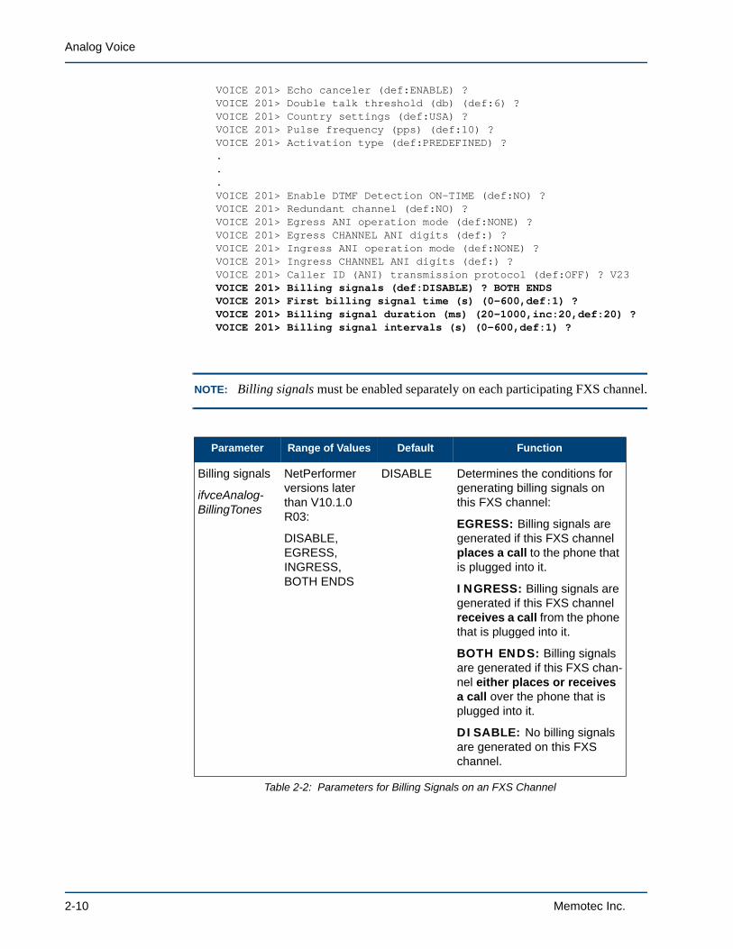
VOICE 201> Echo canceler (def:ENABLE) ?VOICE 201> Double talk threshold (db) (def:6) ?VOICE 201> Country settings (def:USA) ?VOICE 201> Pulse frequency (pps) (def:10) ?VOICE 201> Activation type (def:PREDEFINED) ?...VOICE 201> Enable DTMF Detection ON-TIME (def:NO) ?VOICE 201> Redundant channel (def:NO) ? VOICE 201> Egress ANI operation mode (def:NONE) ?VOICE 201> Egress CHANNEL ANI digits (def:) ?VOICE 201> Ingress ANI operation mode (def:NONE) ?VOICE 201> Ingress CHANNEL ANI digits (def:) ?VOICE 201> Caller ID (ANI) transmission protocol (def:OFF) ? V23VOICE 201> Billing signals (def:DISABLE) ? BOTH ENDSVOICE 201> First billing signal time (s) (0-600,def:1) ?VOICE 201> Billing signal duration (ms) (20-1000,inc:20,def:20) ?VOICE 201> Billing signal intervals (s) (0-600,def:1) ?
NOTE: Billing signals must be enabled separately on each participating FXS channel.
Parameter Range of Values Default Function
Billing signals
ifvceAnalog-BillingTones
NetPerformer versions later than V10.1.0 R03:
DISABLE, EGRESS, INGRESS, BOTH ENDS
DISABLE Determines the conditions for generating billing signals on this FXS channel:
EGRESS: Billing signals are generated if this FXS channel places a call to the phone that is plugged into it.
INGRESS: Billing signals are generated if this FXS channel receives a call from the phone that is plugged into it.
BOTH ENDS: Billing signals are generated if this FXS chan-nel either places or receives a call over the phone that is plugged into it.
DISABLE: No billing signals are generated on this FXS channel.
Table 2-2: Parameters for Billing Signals on an FXS Channel
2-10 Memotec Inc.
Configuring Analog Voice Connections
2.4.2 Configuring Retransmission of Caller ID over an FXS Interface
A caller ID (ANI) received from a remote unit can be sent over an FXS interface on the SDM-9220 and SDM-9230 only. This caller ID is detected by the remote unit:
• On a digital interface such as ISDN or R2. In this case, only the caller ID can be retransmitted by the FXS interface.
• On an analog FXO interface configured for caller ID detection (see next section). In this case, the entire call setup message packet is retransmitted by the FXS interface, including all of its information such as the calling party name, date and time.
NOTE: The caller ID can also be configured on any interface type using the Ingress ANI operation mode and Ingress CHANNEL ANI digits parameters.
For each participating FXS channel you must define the Caller ID (ANI) transmission protocol parameter (SNMP variable: ifvceAnalogCallerID).
• At the console, enter SE SLOT CHANNEL.
• The Caller ID (ANI) transmission protocol parameter appears after the Egress and Ingress ANI parameters. Enter one of the following values:
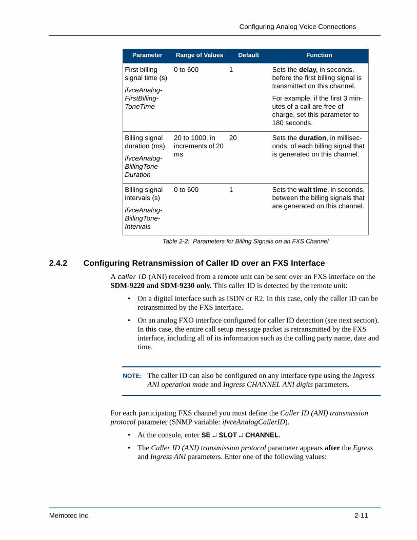
First billing signal time (s)
ifvceAnalog-FirstBilling-ToneTime
0 to 600 1 Sets the delay, in seconds, before the first billing signal is transmitted on this channel.
For example, if the first 3 min-utes of a call are free of charge, set this parameter to 180 seconds.
Billing signal duration (ms)
ifvceAnalog-BillingTone-Duration
20 to 1000, in increments of 20 ms
20 Sets the duration, in millisec-onds, of each billing signal that is generated on this channel.
Billing signal intervals (s)
ifvceAnalog-BillingTone-Intervals
0 to 600 1 Sets the wait time, in seconds, between the billing signals that are generated on this channel.
Parameter Range of Values Default Function
Table 2-2: Parameters for Billing Signals on an FXS Channel
Memotec Inc. 2-11

Analog Voice
- Bell 202: Uses Bell 202 tone modulation at 1200 baud to send the caller ID. This is the best choice for a unit located in North America, Australia, China, Hong Kong or Singapore.
- V23: Uses CCITT V23 modem tones to send the caller ID. This is the best choice for a unit located in Europe.
- OFF: No caller ID is transported over the FXS channel.
NOTE: OFF is the default value. You must change this value to allow the FXS channel to retransmit the caller ID.
Here is an example from the console:
BOSTON>SESETUPItem (BRIDGE/CALLER ID/CLASS/CUSTOM/FILTER/GLOBAL/HUNT/IP/IPX/MAP/PHONE/PORT/PU/PVC/SCHEDULE/SLOT/USER/VLAN,def:SLOT) ?SLOT> Slot number (1/2/3,def:2) ?Item (LINK/CHANNEL,def:LINK) ? CHANNELSLOT> Port number (1-4,def:1) ?VOICE 201> Protocol (def:OFF) ? ACELP-CNVOICE 201> DSP packets per frame 1234VOICE 201> 8K packetization selection (Y/N) ? YNNNVOICE 201> DSP packets per frame 12345VOICE 201> 6K packetization selection (Y/N) ? NNNNNVOICE 201> Comfort noise level (def:0) ?VOICE 201> Local inbound voice level (db) (def:0) ?VOICE 201> Local outbound voice level (db) (def:-3) ?VOICE 201> Priority Level (0-10,def:0) ?VOICE 201> Echo canceler (def:ENABLE) ?VOICE 201> Double talk threshold (db) (def:6) ?VOICE 201> Country settings (def:USA) ?VOICE 201> Pulse frequency (pps) (def:10) ?VOICE 201> Activation type (def:PREDEFINED) ?...VOICE 201> Enable DTMF Detection ON-TIME (def:NO) ?VOICE 201> Redundant channel (def:NO) ? VOICE 201> Egress ANI operation mode (def:NONE) ?VOICE 201> Egress CHANNEL ANI digits (def:) ?VOICE 201> Ingress ANI operation mode (def:NONE) ?VOICE 201> Ingress CHANNEL ANI digits (def:) ?VOICE 201> Caller ID (ANI) transmission protocol (def:OFF) ? BELL 202
2.4.3 Detection of Caller ID on an FXO Interface
A caller ID (ANI) can be detected on an FXO interface on the SDM-9220 and SDM-
2-12 Memotec Inc.
Configuring Analog Voice Connections
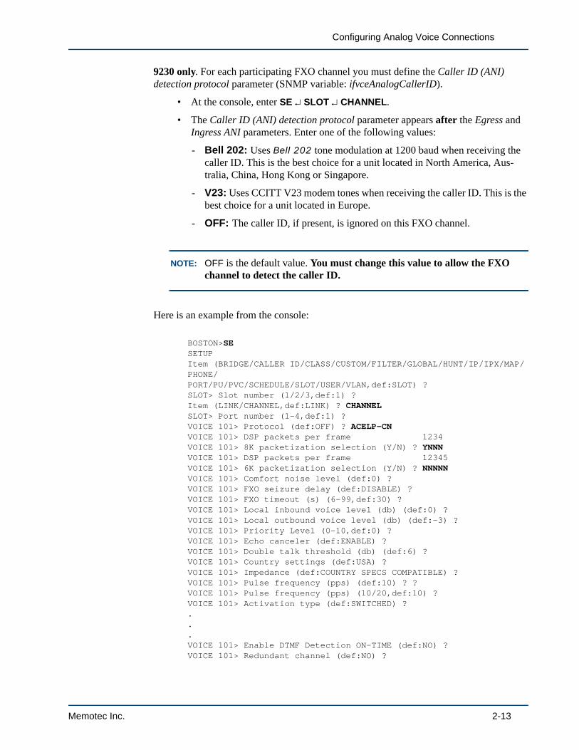
9230 only. For each participating FXO channel you must define the Caller ID (ANI) detection protocol parameter (SNMP variable: ifvceAnalogCallerID).
• At the console, enter SE SLOT CHANNEL.
• The Caller ID (ANI) detection protocol parameter appears after the Egress and Ingress ANI parameters. Enter one of the following values:
- Bell 202: Uses Bell 202 tone modulation at 1200 baud when receiving the caller ID. This is the best choice for a unit located in North America, Aus-tralia, China, Hong Kong or Singapore.
- V23: Uses CCITT V23 modem tones when receiving the caller ID. This is the best choice for a unit located in Europe.
- OFF: The caller ID, if present, is ignored on this FXO channel.
NOTE: OFF is the default value. You must change this value to allow the FXO channel to detect the caller ID.
Here is an example from the console:
BOSTON>SESETUPItem (BRIDGE/CALLER ID/CLASS/CUSTOM/FILTER/GLOBAL/HUNT/IP/IPX/MAP/PHONE/PORT/PU/PVC/SCHEDULE/SLOT/USER/VLAN,def:SLOT) ?SLOT> Slot number (1/2/3,def:1) ?Item (LINK/CHANNEL,def:LINK) ? CHANNELSLOT> Port number (1-4,def:1) ?VOICE 101> Protocol (def:OFF) ? ACELP-CNVOICE 101> DSP packets per frame 1234VOICE 101> 8K packetization selection (Y/N) ? YNNNVOICE 101> DSP packets per frame 12345VOICE 101> 6K packetization selection (Y/N) ? NNNNNVOICE 101> Comfort noise level (def:0) ?VOICE 101> FXO seizure delay (def:DISABLE) ?VOICE 101> FXO timeout (s) (6-99,def:30) ?VOICE 101> Local inbound voice level (db) (def:0) ?VOICE 101> Local outbound voice level (db) (def:-3) ?VOICE 101> Priority Level (0-10,def:0) ?VOICE 101> Echo canceler (def:ENABLE) ?VOICE 101> Double talk threshold (db) (def:6) ?VOICE 101> Country settings (def:USA) ? VOICE 101> Impedance (def:COUNTRY SPECS COMPATIBLE) ? VOICE 101> Pulse frequency (pps) (def:10) ? ?VOICE 101> Pulse frequency (pps) (10/20,def:10) ?VOICE 101> Activation type (def:SWITCHED) ?...VOICE 101> Enable DTMF Detection ON-TIME (def:NO) ?VOICE 101> Redundant channel (def:NO) ?
Memotec Inc. 2-13

Analog Voice
VOICE 101> Egress ANI operation mode (def:NONE) ?VOICE 101> Egress CHANNEL ANI digits (def:) ?VOICE 101> Ingress ANI operation mode (def:NONE) ?VOICE 101> Ingress CHANNEL ANI digits (def:) ?VOICE 101> Caller ID (ANI) detection protocol (def:OFF) ? BELL 202
2-14 Memotec Inc.

Configuring Analog Voice Connections
2.5 Specialized Analog Voice ApplicationsThe NetPerformer supports two analog voice applications designed for special circumstances:
• Hoot and Holler (see next section), used for creating a voice connection that is permanently off-hook.
• Push To Talk (see “Push To Talk” on page 2-15), used for ground-to-air radio communications such as air traffic control, or communications between two remote locations
2.5.1 Hoot and Holler
The NetPerformer supports a Hoot and Holler connection on the E&M interface. A Hoot and Holler connection is a permanent voice connection, that is, one that is always off-hook. The call is always considered up, no matter what signaling information is carried from the user equipment.
To enable this type of connection use the Hoot & Holler application parameter, which is listed at the console for E&M voice channel configuration. The equivalent SNMP variable is ifvceHootHoller.
• When the Hoot & Holler application parameter is set to YES, predefined line activation is used on both sides of the connection.
• When this parameter is set to NO, the line activation type is determined from the Activation type parameter on the voice channel.
2.5.2 Push To Talk
Hardware SupportThe NetPerformer supports a Push To Talk (PTT) application on the E&M interface card.
NOTE: A new Push To Talk 2/4-wire analog interface card is being developed for the NetPerformer SDM-9220/9230 as an alternative to the E&M card. This new interface card:
• Supports applications that cannot use the signaling types available on the E&M interface to carry the PTT signals
• Uses +24 VDC rather than -48VDC for these applications
• Eliminates the need for an expensive PTT to E&M converter.
Contact NetPerformer Technical Support for information on the availability of this new card. Be prepared to provide details on the PTT signal levels required for your application.
Memotec Inc. 2-15

Analog Voice
OperationsPTT is used to key a radio in two different scenarios:
• Scenario 1: From a remote mobile location to a control station, such as an air traffic control application. See Figure 2-2 on “Push-To-Talk Application: Sce-nario 1” on page 2-18.
• Scenario 2: Between two remote locations. See Figure 2-3 on “Push-To-Talk Application: Scenario 2” on page 2-19.
In both of these scenarios:
• The audio path is always up
• The PTT CONTROL device produces M lead transitions on the E&M connection
• The NetPerformer detects these M lead transitions, and regenerates them as E lead transitions
• The E lead transitions are transmitted and replayed at the other end of the connec-tion without clearing the audio path
• As a result, more rapid communications can take place.
In an application involving a fixed control station (Scenario 1):
• The M lead is permanently connected to Signal Ground at the PTT ANSWER side, so that the E&M channel is up at all times
• Only the control station operates as a PTT CONTROL device.
In an application involving two remote locations (Scenario 2):
• The M lead is not permanently connected to Signal Ground at either end of the connection
• The E&M connection goes up and stays up once the first M lead transition occurs, in other words, when the first user at either location presses the talk but-ton
• Users at both locations can use their radio as a PTT CONTROL device, producing transitions on the M lead which the NetPerformer detects and regenerates as E lead transitions at the opposite end of the connection.
Configuring Push To TalkPush To Talk is controlled by the Push to Talk application parameter, which is listed at the console for E&M channel configuration. The equivalent SNMP variable is ifvcePushToTalk.
Scenario 1: To configure the NetPerformer for Push To Talk in an application where a control station communicates with a remote mobile location (Scenario 1):
• Set the Push to Talk application parameter for the E&M channel on the button side of the connection to PTT CONTROL.
2-16 Memotec Inc.

Configuring Analog Voice Connections
This is required for the air traffic controller (Unit 2) in Scenario 1 (see Figure 2-2).
• Set the Push to Talk application parameter for the E&M channel on the mobile unit side to PTT ANSWER.
Scenario 2: To configure the NetPerformer for Push To Talk in an application involving two remote locations (Scenario 2):
• Set the Push to Talk application parameter for the E&M channels on both sides of the connection to PTT CONTROL.
Tip: As a general rule of thumb in any PTT application, if the PTT device has a control button, you can set the corresponding E&M channel to PTT CONTROL.
Memotec Inc. 2-17

Analog Voice
Figure 2-2: Push-To-Talk Application: Scenario 1
P1
P2
Unit 1
S1
1CH
P1
M lead
PTT Answer
Air-ground-Air radio
TX audio pair
RX audiopair
Radio tower
P2
S1
1CH
PTT Control
M lead
Unit 2
PORT #100> Status...............................ENABLEPORT #100> Pcm encoding law.....................A-LAWVOICE #101> Protocol............................PCM64KVOICE #101> E&M signaling type..................IMMEDIATE STARTVOICE #101> Analog E&M type.....................4 WIREVOICE #101> TE timer (sec)......................0VOICE #101> Hoot & Holler application...........NOVOICE #101> Push to Talk application............PTT ANSWERVOICE #101> Silence suppression level...........1VOICE #101> Local inbound voice level (db)......-3VOICE #101> Local outbound voice level (db).....0VOICE #101> Priority Level......................0VOICE #101> Echo canceler.......................DISABLEVOICE #101> Pulse frequency (pps)...............10VOICE #101> Activation type.....................PREDEFINEDVOICE #101> Link down busy......................YESVOICE #101> TONE type:..........................DTMFVOICE #101> TONE regeneration:..................1VOICE #101> TONE ON (msec)......................100VOICE #101> TONE OFF (msec).....................100VOICE #101> Pulse make/break ratio..............34VOICE #101> Fax/modem relay.....................NONEVOICE #101> Remote unit........................SDM9585#3VOICE #101> Remote port number..................101VOICE #101> Accept incoming ATM AAL1 calls......NOVOICE #101> Egress ANI operation mode...........NONEVOICE #101> Egress CHANNEL ANI digits...........VOICE #101> Ingress ANI operation mode..........NONEVOICE #101> Ingress CHANNEL ANI digits..........
Unit 1 Configuration:
PORT #100> Status...............................ENABLEPORT #100> Pcm encoding law.....................A-LAWVOICE #101> Protocol............................PCM64KVOICE #101> E&M signaling type..................IMMEDIATE STARTVOICE #101> Analog E&M type.....................4 WIREVOICE #101> TE timer (sec)......................0VOICE #101> Hoot & Holler application...........NOVOICE #101> Push to Talk application............PTT CONTROLVOICE #101> Silence suppression level...........1VOICE #101> Local inbound voice level (db)......-3VOICE #101> Local outbound voice level (db).....0VOICE #101> Priority Level......................0VOICE #101> Echo canceler.......................DISABLEVOICE #101> Pulse frequency (pps)...............10VOICE #101> Activation type.....................PREDEFINEDVOICE #101> Link down busy......................YESVOICE #101> TONE type:..........................DTMFVOICE #101> TONE regeneration:..................1VOICE #101> TONE ON (msec)......................100VOICE #101> TONE OFF (msec).....................100VOICE #101> Pulse make/break ratio..............34VOICE #101> Fax/modem relay.....................NONEVOICE #101> Remote unit.........................SDM9585#1VOICE #101> Remote port number..................101VOICE #101> Accept incoming ATM AAL1 calls......NOVOICE #101> Egress ANI operation mode...........NONEVOICE #101> Egress CHANNEL ANI digits...........VOICE #101> Ingress ANI operation mode..........NONEVOICE #101> Ingress CHANNEL ANI digits..........
Unit 2 Configuration:
Air TrafficController
Mobile Unit
E lead E lead
2-18 Memotec Inc.

Configuring Analog Voice Connections
Figure 2-3: Push-To-Talk Application: Scenario 2
P1
PORT #100> Status...............................ENABLEPORT #100> Pcm encoding law.....................A-LAWVOICE #101> Protocol............................PCM64KVOICE #101> E&M signaling type..................IMMEDIATE STARTVOICE #101> Analog E&M type.....................4 WIREVOICE #101> TE timer (sec)......................0VOICE #101> Hoot & Holler application...........NOVOICE #101> Push to Talk application............PTT CONTROLVOICE #101> Silence suppression level...........1VOICE #101> Local inbound voice level (db)......-3VOICE #101> Local outbound voice level (db).....0VOICE #101> Priority Level......................0VOICE #101> Echo canceler.......................DISABLEVOICE #101> Pulse frequency (pps)...............10VOICE #101> Activation type.....................PREDEFINEDVOICE #101> Link down busy......................YESVOICE #101> TONE type:..........................DTMFVOICE #101> TONE regeneration:..................1VOICE #101> TONE ON (msec)......................100VOICE #101> TONE OFF (msec).....................100VOICE #101> Pulse make/break ratio..............34VOICE #101> Fax/modem relay.....................NONEVOICE #101> Remote unit........................SDM9585#3VOICE #101> Remote port number..................101VOICE #101> Accept incoming ATM AAL1 calls......NOVOICE #101> Egress ANI operation mode...........NONEVOICE #101> Egress CHANNEL ANI digits...........VOICE #101> Ingress ANI operation mode..........NONEVOICE #101> Ingress CHANNEL ANI digits..........
Unit 1 Configuration:
PORT #100> Status...............................ENABLEPORT #100> Pcm encoding law.....................A-LAWVOICE #101> Protocol............................PCM64KVOICE #101> E&M signaling type..................IMMEDIATE STARTVOICE #101> Analog E&M type.....................4 WIREVOICE #101> TE timer (sec)......................0VOICE #101> Hoot & Holler application...........NOVOICE #101> Push to Talk application............PTT CONTROLVOICE #101> Silence suppression level...........1VOICE #101> Local inbound voice level (db)......-3VOICE #101> Local outbound voice level (db).....0VOICE #101> Priority Level......................0VOICE #101> Echo canceler.......................DISABLEVOICE #101> Pulse frequency (pps)...............10VOICE #101> Activation type.....................PREDEFINEDVOICE #101> Link down busy......................YESVOICE #101> TONE type:..........................DTMFVOICE #101> TONE regeneration:..................1VOICE #101> TONE ON (msec)......................100VOICE #101> TONE OFF (msec).....................100VOICE #101> Pulse make/break ratio..............34VOICE #101> Fax/modem relay.....................NONEVOICE #101> Remote unit.........................SDM9585#1VOICE #101> Remote port number..................101VOICE #101> Accept incoming ATM AAL1 calls......NOVOICE #101> Egress ANI operation mode...........NONEVOICE #101> Egress CHANNEL ANI digits...........VOICE #101> Ingress ANI operation mode..........NONEVOICE #101> Ingress CHANNEL ANI digits..........
Unit 2 Configuration:
P1
P2
S1
1CH
PTT Control
M lead
Unit 2
E lead
P2
Unit 1
1CH S
1PTT Control
M lead
E lead
Memotec Inc. 2-19

Analog Voice
2-20 Memotec Inc.

3
Configuring the Voice Mapping TableMemotec Inc. 3-1

Analog Voice
3.1 About the Voice Mapping TableThe Voice Mapping Table includes definitions of all dial numbers used for call setup on a voice channel. On the NetPerformer base product, it defines all Speed Dial Numbers that are used for voice channels configured with SWITCHED or AUTODIAL activation.
You can add, modify or delete a MAP entry.
NOTE: The MAP entries cannot be defined using SNMP.
A total of 1000 MAP entries can be defined in the Voice Mapping Table, allowing for a total of 1000 Speed Dial Numbers.
NOTE: If you have a large number of Voice Mapping Table entries to configure, you may prefer to upload or download the Map file using FTP. Refer to “Upload-ing or Downloading the MAP File” on page 3-8.
Figure 3-1: SETUP/MAP Path in the CLI Tree
Unit ID>(main prompt)
Setup (SE)
MAP
DELETEADD MODIFY
3-2 Memotec Inc.

Configuring the Voice Mapping Table
3.2 Adding a MAP EntryTo define a new MAP entry for a SWITCHED or AUTODIAL voice channel:
1. Enter the menu sequence: SE MAP
2. Set the Operation to ADD
3. Enter an Entry digits string. The character * can be used as a wildcard character, if desired.
- With the Voice Traffic Routing (VTR) function, the character ! (exclamation mark) can be used as a special wildcard character to concatenate user-dialed digits to the extended digits. During call setup the ! is replaced by the extended digits dialed by the user. For details on VTR, consult the Advanced Voice Features fascicle of this document series.
- An overloaded MAP entry can be configured if you enter the Entry digits string of a currently defined MAP entry. The current MAP entry is listed first, followed by the confirmation prompt:
MAP> Do you want to overload this entry (NO/YES,def:YES) ?
Enter YES to continue with overloaded MAP entry configuration. An example is provided on “SE/MAP/ADD example” on page 3-4 (MAP 1.2).
4. Set the Destination name to the Unit name of the remote NetPerformer. Use * as a wildcard character, if desired.
5. Specify the Destination extension source:
- HUNT: The call will be connected to the first available voice channel on the destination unit that belongs to a specific Hunt Group
NOTE: Specify the desired Hunt group (A to F)
- USER: The call will be connected to the destination extension number that the user dials (after dialing the Speed Dial Number)
- MAP: The call will be connected to the extension number defined in this MAP entry
NOTE: Specify the desired Destination extension.
6. Specify the Extended digits source, if required:
- NONE: No extended digits are forwarded to the remote side
- USER: The user dials the extended digits that are forwarded to the remote side
Memotec Inc. 3-3

Analog Voice
NOTE: Specify the Number of user extended digits that can be dialed.
- MAP: The extended digits are taken from this MAP entry
NOTE: Specify the desired Extended digits to forward.
7. Set Use SVC connection to YES to allow an SVC to be defined on this voice channel
8. If using an SVC connection, change the other SVC parameters from their default values, if desired
9. Enter YES at the Add another map entry prompt if you would like to create another new MAP entry.
SE/MAP/ADD example SDM-9230>SE
SETUPItem (BRIDGE/CALLER ID/CLASS/CUSTOM/FILTER/GLOBAL/HUNT/IP/IPX/MAP/PHONE/PORT/PU/PPPOE/PPPUSER/PVC/REDUNDANCY/SCHEDULE/SLOT/USER/VLAN,def:BRIDGE) ? MAPMAP> Operation (ADD/MODIFY/DELETE,def:ADD) ?
MAP 1: Calls any extension in a Hunt Group
MAP > Entry digits (def:) ? 459MAP 1> Destination name (def:) ? CHICAGO-9230MAP 1> Destination extension source (def:HUNT) ? MAP 1> Hunt group (def:A) ? MAP 1> Extended digits source (def:NONE) ? MAP 1> Use SVC connection (def:NO) ?MAP> Add another map entry (NO/YES,def:NO) ? YES
MAP 2: Calls a specific extension number, dialed by the user
MAP > Entry digits (def:) ? 123MAP 2> Destination name (def:) ? CHICAGO-9220MAP 2> Destination extension source (def:HUNT) ? USERMAP 2> Extended digits source (def:NONE) ? USERMAP 2> Number of user extended digits (0-27,def:0) ? 3MAP 2> Use SVC connection (def:NO) ? YESMAP 2> SVC address type (def:E.164) ? MAP 2> SVC network address (def:) ? 45600731MAP> Add another map entry (NO/YES,def:NO) ? YES
MAP 3: Calls a specific extension number, defined in the MAP entry
MAP > Entry digits (def:) ? 12345MAP 3> Destination name (def:) ? MONTREAL-9230MAP 3> Destination extension source (def:HUNT) ? MAPMAP 3> Destination extension (def:) ? 123MAP 3> Extended digits source (def:NONE) ? MAPMAP 3> Extended digits to forward (def:) ? 1220MAP 3> Use SVC connection (def:NO) ? MAP> Add another map entry (NO/YES,def:NO) ? YES
3-4 Memotec Inc.

Configuring the Voice Mapping Table
MAP 1 renamed MAP 1.1 when a new MAP entry uses the same Entry digits
MAP > Entry digits (def:) ? 459
MAP 1.1> Map type...............................NAMEMAP 1.1> Entry digits...........................1MAP 1.1> Destination name.......................CHICAGO-9230MAP 1.1> Destination extension source...........HUNTMAP 1.1> Hunt group.............................AMAP 1.1> Extended digits source.................NONEMAP 1.1> Use SVC connection.....................NO
MAP> Do you want to overload this entry (NO/YES,def:YES) ? YES
MAP 1.2: Defines an overloaded MAP entry
MAP> Position of the map to add (1-2,def:2) ? 2MAP 1.2> Destination name (def:) ? BOSTON-8400MAP 1.2> Destination extension source (def:HUNT) ?MAP 1.2> Hunt group (def:A) ?MAP 1.2> Extended digits source (def:NONE) ? USERMAP 1.2> Number of user extended digits (0-30,def:0) ? 23MAP 1.2> Use SVC connection (def:NO) ? YESMAP 1.2> SVC address type (def:E.164) ? MAP 1.2> SVC network address (def:) ? 0MAP> Add another map entry (NO/YES,def:NO) ?
These parameters are detailed in “SE/MAP Configuration Parameters” on page 8-1.
Memotec Inc. 3-5
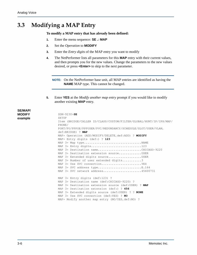
Analog Voice
3.3 Modifying a MAP EntryTo modify a MAP entry that has already been defined:
1. Enter the menu sequence: SE MAP
2. Set the Operation to MODIFY
3. Enter the Entry digits of the MAP entry you want to modify
4. The NetPerformer lists all parameters for this MAP entry with their current values, and then prompts you for the new values. Change the parameters to the new values desired, or press <Enter> to skip to the next parameter.
NOTE: On the NetPerformer base unit, all MAP entries are identified as having the NAME MAP type. This cannot be changed.
5. Enter YES at the Modify another map entry prompt if you would like to modify another existing MAP entry.
SE/MAP/MODIFY example
SDM-9230>SESETUPItem (BRIDGE/CALLER ID/CLASS/CUSTOM/FILTER/GLOBAL/HUNT/IP/IPX/MAP/PHONE/PORT/PU/PPPOE/PPPUSER/PVC/REDUNDANCY/SCHEDULE/SLOT/USER/VLAN,def:BRIDGE) ? MAPMAP> Operation (ADD/MODIFY/DELETE,def:ADD) ? MODIFYMAP> Entry digits (def:) ? 123MAP 3> Map type.................................NAMEMAP 3> Entry digits.............................123MAP 3> Destination name.........................CHICAGO-9220MAP 3> Destination extension source.............USERMAP 3> Extended digits source...................USERMAP 3> Number of user extended digits...........3MAP 3> Use SVC connection.......................YESMAP 3> SVC address type.........................E.164MAP 3> SVC network address......................45600731
MAP 3> Entry digits (def:123) ?MAP 3> Destination name (def:CHICAGO-9220) ?MAP 3> Destination extension source (def:USER) ? MAPMAP 3> Destination extension (def:) ? 456MAP 3> Extended digits source (def:USER) ? ? NONEMAP 3> Use SVC connection (def:YES) ? NOMAP> Modify another map entry (NO/YES,def:NO) ?
3-6 Memotec Inc.

Configuring the Voice Mapping Table
3.4 Deleting a MAP EntryTo delete an entry from the Voice Mapping Table:
1. Enter the menu sequence: SE MAP
2. Set the Operation to DELETE
3. Enter the Entry digits of the MAP entry you want to delete
Caution: The MAP entry will be deleted immediately, with no confirma-tion requested. Enter the Entry digits with care.
4. Enter YES at Delete another map entry if you would like to delete another currently defined MAP entry.
NOTE: You can delete all entries in the Voice Mapping Table simultaneously with the Erase Map File (EMF) command. Enter EMF at the console command prompt.
SE/MAP/DELETE example
SDM-9230>SESETUPItem (BRIDGE/CALLER ID/CLASS/CUSTOM/FILTER/GLOBAL/HUNT/IP/IPX/MAP/PHONE/PORT/PU/PPPOE/PPPUSER/PVC/REDUNDANCY/SCHEDULE/SLOT/USER/VLAN,def:BRIDGE) ? MAPMAP> Operation (ADD/MODIFY/DELETE,def:MODIFY) ? DELETEMAP> Entry digits (def:) ? 123MAP> Delete another map entry (NO/YES,def:NO) ?
Memotec Inc. 3-7
Analog Voice
3.5 Uploading or Downloading the MAP FileIf you have a large number of Voice Mapping Table entries to configure, you can upload or download the MAP file from another NetPerformer unit using FTP.
Caution: Before transferring a MAP file, ensure that the MAP file versions on the two units are compatible. On each unit, view the current setting of the global Extended Parameter MAPVERSION, which defines the format of the Voice Mapping Table used on the unit. MAP files are not backward compatible. Do not replace a MAP file with one that has a lower numbered version. For assistance, contact NetPerformer Technical Support.
To download a MAP file from another NetPerformer unit:
1. Access the unit using FTP
2. Execute the get command, specifying the MAP filename (MAP.TXT)
3. After transfer is complete, change the filename to reflect the name of your NetPerformer product, using the RENAME command from the console.
To upload a MAP file to another NetPerformer unit:
1. Access the unit using FTP
2. Execute the put command, specifying the appropriate local MAP filename
3. After transfer is complete, change the filename to reflect the product name of the destination unit.
3-8 Memotec Inc.

4
Monitoring Analog Voice ConnectionsMemotec Inc. 4-1

Analog Voice
4.1 About the NetPerformer console commandThe following areas of the NetPerformer console command set provide information on how analog voice connections are operating in your network and the current configuration of parameters involved:
• To view the current status of a voice channel, use the SLOT option of the Display States (DS) command
• For a display of channel status in real time, execute the Display Call States (DCS) command
• To view the number and type of errors that have occurred on an interface card and its channels, use the SLOT option of the Display Errors (DE) command
• To view the current values of all analog voice parameters, use the SLOT option of the Display Parameters (DP) command.
4.1.1 Display States (DS)
To display the current status of an analog interface card:
1. At the console command line, enter the menu sequence: DS SLOT
2. Select the Slot number of the analog interface card.
DS/SLOT example: on an FXS interface card
SDM-9230>DSDISPLAY STATESItem (GLOBAL/PORT/PU/PVC/SLOT/SVC/VLAN,def:GLOBAL) ? SLOTSLOT> Slot number (1/2/3/ALL,def:1) ? 3SLOT 3>PORT 300> State.................................ENABLE
VOICE 301> State................................IDLEVOICE 301> Protocol.............................ACELP-CNVOICE 301> Last error...........................NONEVOICE 301> DSP relay rate.......................NO DSP
Figure 4-1: Statistics Commands in the CLI Tree for Analog Interface Cards
Unit ID>(main prompt)
Display Call States(DCS)
Display States(DS)
Slot (SL)
Display Errors(DE)
Slot (SL)
Display Parameters(DP)
Slot (SL)
4-2 Memotec Inc.

Monitoring Analog Voice Connections
VOICE 301> DSP relay mode.......................NO DSP
VOICE 302> State................................IDLEVOICE 302> Protocol.............................PCM64KVOICE 302> Last error...........................NONEVOICE 302> DSP relay rate.......................NO DSPVOICE 302> DSP relay mode.......................NO DSP
VOICE 303> State................................IDLEVOICE 303> Protocol.............................ACELP-CNVOICE 303> Last error...........................NEW PARMSVOICE 303> DSP relay rate.......................NO DSPVOICE 303> DSP relay mode.......................NO DSP
VOICE 304> State................................IDLEVOICE 304> Protocol.............................PCM64KVOICE 304> Last error...........................NONEVOICE 304> DSP relay rate.......................NO DSPVOICE 304> DSP relay mode.......................NO DSP
Modem signals: d(S)r d(T)r (D)cd (R)ts (C)ts r(I) (-)off
4.1.2 Display Channel States (DCS)
The Display Channel States command (DCS) shows the status of all analog and digital channels in real time. To execute this command:
• Enter DCS at the console command prompt.
DCS example: on an FXS interface card
CHICAGO>DCSDISPLAY CHANNEL STATES
----------------------------------- SLOT 3 : FXS ------------------------------| # Status Remote Unit Name # Rate | # Status Remote Unit Name # Rate ||301 ONLINE 9350 1 8.0Kx1| || | || | || | || | || | || | || | || | || | || | || | || | || | || | || | |-------------------------------------------------------------------------------
Use LEFT and RIGHT arrow keys to change slot. Press any other key to exit.
4.1.3 Display Errors (DE)
To display the number and type of errors that have occurred on an analog interface card:
Memotec Inc. 4-3

Analog Voice
1. At the console command line, enter the menu sequence: DE SLOT
2. Select the Slot number of the analog interface card.
DE/SLOT example: on an FXS interface card
SDM-9230>DEDISPLAY ERRORSItem (BOOTP/CHANNEL/DICT/GROUP/NAT/PORT/PU/PVC/Q922/SLOT/SVC/TIMEP,def:BOOTP) ? SLOTSLOT> Slot number (1/2/3/ALL,def:1) ? 3SLOT 3>VOICE 301> Number of overruns...................0VOICE 301> Number of underruns..................0VOICE 301> No DSP available.....................0
VOICE 302> Number of overruns...................0VOICE 302> Number of underruns..................0VOICE 302> No DSP available.....................0
VOICE 303> Number of overruns...................0VOICE 303> Number of underruns..................0VOICE 303> No DSP available.....................0
VOICE 304> Number of overruns...................0VOICE 304> Number of underruns..................0VOICE 304> No DSP available.....................0
Bad flags: U:Bad LENGTH Q:Overflow F:Flush S:Overrun B:Bad CRC A:Abort
4.1.4 Display Configuration Parameters (DP)
The DP command provides a complete list of current values for all configuration parameters. To display the analog voice configuration parameters and their values:
1. At the console command line, enter the menu sequence: DP SLOT
2. Select the Slot number of the analog interface card.
DP/SLOT example: on an FXO interface card
SDM-9230>DPDISPLAY PARAMETERSItem (BRIDGE/CALLER ID/CLASS/CUSTOM/FILTER/GLOBAL/HUNT/IP/IPX/MAP/PHONE/PORT/PU/PPPOE/PPPUSER/PVC/REDUNDANCY/SCHEDULE/SLOT/USER/VLAN,def:BRIDGE) ? SLOTSLOT> Slot number (1/2/3,def:1) ?PORT 100> Status................................ENABLEPORT 100> Pcm encoding law......................MU-LAWVOICE 101> Protocol.............................ACELP-CNVOICE 101> DSP packets per frame 1234VOICE 101> 8K packetization selection (Y/N)....YNNNVOICE 101> DSP packets per frame 12345VOICE 101> 6K packetization selection (Y/N)....NNNNN
4-4 Memotec Inc.

Monitoring Analog Voice Connections
VOICE 101> Comfort noise level..................0VOICE 101> FXO seizure delay....................ENABLEVOICE 101> FXO timeout (s)....................30VOICE 101> Local inbound voice level (db).......0VOICE 101> Local outbound voice level (db)......-3VOICE 101> Priority Level.......................0VOICE 101> Echo canceler........................ENABLEVOICE 101> Double talk threshold (db)...........6VOICE 101> Country settings.....................CANADAVOICE 101> Impedance............................GLOBAL COMPLEX IMPEDANCEVOICE 101> Pulse frequency (pps)................10VOICE 101> Activation type......................PREDEFINEDVOICE 101> Link down busy.......................NOVOICE 101> TONE type:...........................DTMFVOICE 101> TONE regeneration:...................1VOICE 101> TONE ON (ms).......................100VOICE 101> TONE OFF (ms)......................100VOICE 101> Pulse make/break ratio...............34VOICE 101> Fax relay............................FAXVOICE 101> Maximum fax rate.....................14400VOICE 101> ECM mode.............................DISABLEVOICE 101> Modem relay..........................NONEVOICE 101> Remote unit..........................NONEVOICE 101> Remote port number...................101VOICE 101> Enable DTMF Detection ON-TIME........NOVOICE 101> Redundant channel....................NOVOICE 101> Egress ANI operation mode............NONEVOICE 101> Egress CHANNEL ANI digits............VOICE 101> Ingress ANI operation mode...........NONEVOICE 101> Ingress CHANNEL ANI digits...........VOICE 101> Caller ID (ANI) detection protocol...OFF...
Memotec Inc. 4-5

Analog Voice
4-6 Memotec Inc.

5
Calling ProceduresMemotec Inc. 5-1

Analog Voice
5.1 Initiating a Call
NOTE: This section describes the predefined and switched line activation types only. Autodial is initiated in the same manner as predefined line activation. Broad-cast initiation is described in “Broadcast Line Activation” on page 1-18.
5.1.1 Predefined and Autodial Line Activation
To initiate a call when the local and remote voice ports of the NetPerformer are configured with predefined or Autodial line activation:
• Pick up the telephone receiver (at either the local or remote site).
• The call is placed automatically, and the telephone at the other end will ring.
5.1.2 Switched Line Activation
When the local and remote voice ports of the NetPerformer are configured with voice switching, the call must be initiated manually using a speed dial number that has been configured for the NetPerformer using the Setup Map menu:
Interfaces(local - remote)
Connected Equipment(local - remote)
To Initiate a Call(from local site)
FXS - FXS Telephone - Telephone a) Dial the speed dial number,b) Dial the remote extension number if it is not sent automatically.
FXS - FXS Telephone - FXO equipment a) Dial the speed dial number,b) Dial the remote extension number if it is not sent automatically,c) Ask key telephone system attendant for the desired line.
FXS - FXS FXO equipment - Telephone a) Select a free line on the key telephone system,b) Dial the speed dial number,c) Dial the remote extension number if it is not sent automatically.
FXS - FXS FXO equipment - FXO equipment a) Select a free line on the key telephone system,b) Dial the speed dial number,c) Dial the remote extension number if it is not sent automatically,d) Ask key telephone system attendant for the desired line.
Table 5-1: Initiation Sequence for Switched Line Activation
5-2 Memotec Inc.

Calling Procedures
FXS - FXO Telephone - CO a) Dial the speed dial number,b) Dial the remote extension number if it is not sent automatically,c) Dial the required telephone number for the CO to place the call.
FXS - FXO FXO equipment - CO a) Select a free line on the key telephone system,b) Dial the speed dial number,c) Dial the remote extension number if it is not sent automatically,d) Dial the required telephone number for the CO to place the call.
FXS - FXO Telephone - PBX station side a) Dial the speed dial number,b) Dial the remote extension number if it is not sent automatically,c) Dial the required extended digits for the PBX to place the call, if they are not automatically forwarded.
FXS - FXO FXO equipment - PBX station side a) Select a free line on the key telephone system,b) Dial the speed dial number,c) Dial the remote extension number if it is not sent automatically,c) Dial the required extended digits for the PBX to place the call, if they are not automatically forwarded.
FXO - FXS CO - Telephone a) Dial the required telephone number for the CO to place a call to the NetPer-former,b) Dial the speed dial number,c) Dial the remote extension number if it is not sent automatically.
FXO - FXS PBX station side - Telephone a) Dial the required digit sequence for the PBX to place a call to the NetPerformer,b) Dial the speed dial number,c) Dial the remote extension number if it is not sent automatically.
Interfaces(local - remote)
Connected Equipment(local - remote)
To Initiate a Call(from local site)
Table 5-1: Initiation Sequence for Switched Line Activation
Memotec Inc. 5-3

Analog Voice
FXO - FXS CO - FXO equipment a) Dial the required telephone number for the CO to place a call to the NetPer-former,b) Dial the speed dial number,c) Dial the remote extension number if it is not sent automatically,d) Ask key telephone system attendant for the desired line.
FXO - FXS PBX station side - FXO equipment a) Dial the required digit sequence for the PBX to place a call to the NetPerformer,b) Dial the speed dial number,c) Dial the remote extension number if it is not sent automatically,d) Ask key telephone system attendant for the desired line.
E&M - E&M PBX trunk side - PBX trunk side a) Select the PBX line for the NetPer-former trunk, for example, “8”,b) Dial the speed dial number,c) Dial the remote extension number if it is not sent automatically,d) If remote PBX has an operator, ask for the desired line. Otherwise, dial the required extended digits if they are not sent automatically.
E&M - FXS PBX trunk side - Telephone a) Select the PBX line for the NetPer-former trunk, for example, “8”,b) Dial the speed dial number,c) Dial the remote extension number if it is not sent automatically.
E&M - FXS PBX trunk side - FXO equipment a) Select the PBX line for the NetPer-former trunk, for example, “8”,b) Dial the speed dial number,c) Dial the remote extension number if it is not sent automatically,d) Ask key telephone system attendant for the desired line.
E&M - FXO PBX trunk side - CO a) Select the PBX line for the NetPer-former trunk, for example, “8”,b) Dial the speed dial number,c) Dial the remote extension number if it is not sent automatically,d) Dial the required telephone number for the CO to place the call.
Interfaces(local - remote)
Connected Equipment(local - remote)
To Initiate a Call(from local site)
Table 5-1: Initiation Sequence for Switched Line Activation
5-4 Memotec Inc.
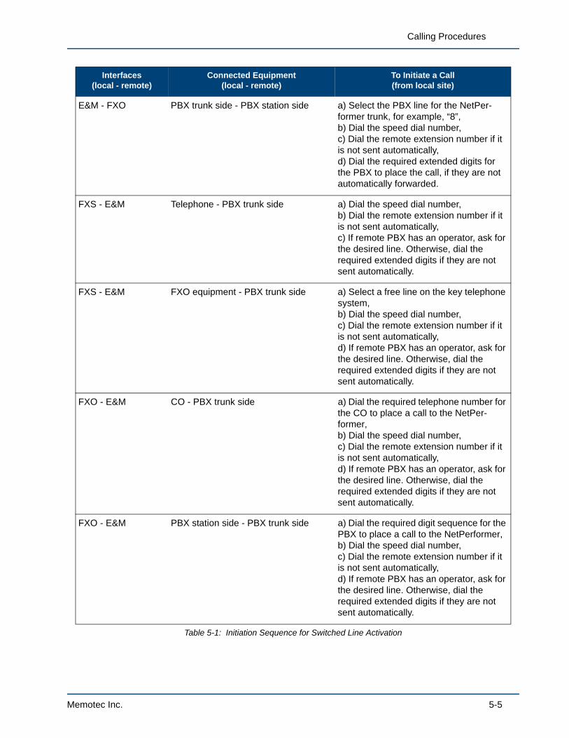
Calling Procedures
E&M - FXO PBX trunk side - PBX station side a) Select the PBX line for the NetPer-former trunk, for example, “8”,b) Dial the speed dial number,c) Dial the remote extension number if it is not sent automatically,d) Dial the required extended digits for the PBX to place the call, if they are not automatically forwarded.
FXS - E&M Telephone - PBX trunk side a) Dial the speed dial number,b) Dial the remote extension number if it is not sent automatically,c) If remote PBX has an operator, ask for the desired line. Otherwise, dial the required extended digits if they are not sent automatically.
FXS - E&M FXO equipment - PBX trunk side a) Select a free line on the key telephone system,b) Dial the speed dial number,c) Dial the remote extension number if it is not sent automatically,d) If remote PBX has an operator, ask for the desired line. Otherwise, dial the required extended digits if they are not sent automatically.
FXO - E&M CO - PBX trunk side a) Dial the required telephone number for the CO to place a call to the NetPer-former,b) Dial the speed dial number,c) Dial the remote extension number if it is not sent automatically,d) If remote PBX has an operator, ask for the desired line. Otherwise, dial the required extended digits if they are not sent automatically.
FXO - E&M PBX station side - PBX trunk side a) Dial the required digit sequence for the PBX to place a call to the NetPerformer,b) Dial the speed dial number,c) Dial the remote extension number if it is not sent automatically,d) If remote PBX has an operator, ask for the desired line. Otherwise, dial the required extended digits if they are not sent automatically.
Interfaces(local - remote)
Connected Equipment(local - remote)
To Initiate a Call(from local site)
Table 5-1: Initiation Sequence for Switched Line Activation
Memotec Inc. 5-5

Analog Voice
5.2 Terminating a Call
NOTE: This section describes the predefined and switched line activation types only. Autodial is terminated in the same manner as predefined line activation. Broadcast termination is described in “Broadcast Line Activation” on page 1-18.
5.2.1 Predefined and Autodial Line Activation
To terminate a call when the local and remote voice ports of the NetPerformer are configured with predefined or Autodial line activation:
• Hang up the telephone receiver (at either the local or remote site),
• The telephone at the other end will detect the on-hook condition, and terminate the connection.
5.2.2 Switched Line Activation
When the local and remote voice ports of the NetPerformer are configured with voice switching, the way the call is terminated depends on the connected voice/fax equipment. Only those devices that can detect an ON HOOK condition are able to terminate a call. Thus when one side of the connection is a CO or the station side of a PBX (an FXO interface on the NetPerformer), the other side is responsible for terminating the call.
Interfaces(local - remote)
Connected Equipment(local - remote)
To Initiate a Call(from local site)
FXS - FXS Telephone/FXO equipment - Tele-phone/FXO equipment
Local or remote user hangs up.
FXS - FXO Telephone/FXO equipment - CO/PBX station side
Local user hangs up.
FXO - FXS CO/PBX station side - Telephone/FXO equipment
Remote user hangs up.
E&M - E&M PBX trunk side - PBX trunk side Local or remote user hangs up.
E&M - FXS PBX trunk side - Telephone/FXO equipment
Local or remote user hangs up.
E&M - FXO PBX trunk side - CO/ PBX station side Local user hangs up.
FXS - E&M Telephone/FXO equipment - PBX trunk side
Local or remote user hangs up.
Table 5-2: Termination Sequence for Switched Line Activation
5-6 Memotec Inc.

Calling Procedures
FXO - E&M CO/PBX station side - PBX trunk side Remote user hangs up.
Interfaces(local - remote)
Connected Equipment(local - remote)
To Initiate a Call(from local site)
Table 5-2: Termination Sequence for Switched Line Activation
Memotec Inc. 5-7

Analog Voice
5.3 Examples of Calling ProceduresIn this section we present several NetPerformer voice/fax applications, and describe the calling procedures that take place when a call is initiated and terminated.
5.3.1 FXS-to-FXS Application with Predefined Line Activation
This application supports several switched telephones, and uses predefined line activation to send corporate information between two “hot line” telephones. The voice port configuration of the two NetPerformers specifies the connection between Tel A in Montreal and Tel B in Toronto.
Tel A is connected to voice port 2 on the local NetPerformer. Thus voice port 2 on the unit MONTREAL is configured with:
• Activation Type: PREDEFINED
• Remote unit: TORONTO
• Remote port number: 1
Tel B is connected to voice port 1 on the remote NetPerformer. Thus voice port 1 on the unit TORONTO is configured with:
• Activation Type: PREDEFINED
• Remote unit: MONTREAL
• Remote port number: 2
NOTE: Predefined line activation will work only if each port specifies the other as its destination. This is the first thing to check if you have problems connecting to the remote end.
Figure 5-1: FXS-to-FXS Application with Predefined Line Activation
MONTREAL TORONTO1
2
2
1
Tel A Tel B
FXSFXS
PredefinedLine Activation
5-8 Memotec Inc.

Calling Procedures
Here is the calling procedure that takes place when initiating and terminating a call in this configuration:
• The user at Tel A in Montreal lifts the telephone receiver (Tel A goes off-hook). The local NetPerformer immediately requests line activation with the remote NetPerformer at the Toronto site.
• The remote NetPerformer rings Tel B by applying a physical ring signal on the port connected to Tel B. At the same time, the Toronto unit notifies the Montreal unit that it is ringing Tel B. The NetPerformer in Montreal then generates a ring-back tone at Tel A.
• The user at Tel B lifts the telephone receiver (Tel B goes off-hook). The off-hook condition is detected by the local NetPerformer, which notifies the Montreal unit to stop the ringback tone
• As soon as both ends are off-hook, a closed loop is created for transmission of voice data. Full duplex voice transmission is carried over the trunk as long as both telephones remain off hook.
• At the end of the conversation, the user at Tel B hangs up the telephone receiver (Tel B goes on-hook). The NetPerformer at the Montreal site detects the on-hook condition and deactivates the virtual connection to the NetPerformer in Toronto.
NOTE: The local NetPerformer must detect an on-hook condition before a second call can be placed. Otherwise, a busy signal will be detected, and the local unit will generate an audio busy signal at Tel A.
Memotec Inc. 5-9

Analog Voice
5.3.2 E&M-to-E&M Application with Voice Switching
In this application, Tel A in Montreal will initiate and then terminate a call to Tel G in London.
• The user at Tel A lifts the telephone receiver (Tel A goes off-hook) and hears the dial tone from PBX A.
• The user dials “8” to access an available E&M trunk from PBX A to the local NetPerformer at the Montreal site.
• The local NetPerformer detects the off-hook condition, and generates a local dial tone at Tel A.
• The user dials the speed dial number “56”.
• The local NetPerformer looks in its Voice Mapping Table, determines that speed dial number 56 is associated with the London site and that the extension number is any port configured with Hunt Group B active.
• The local NetPerformer opens a virtual connection with the remote NetPerformer in London, and sends a command to the London unit requesting connection to the first available switched port that has Hunt Group B active.
• The NetPerformer in London selects the first free port with Hunt Group B active that is available to take the call. In this example, voice ports 1 and 2 are config-ured as switched E&M with Hunt Group B active. The London unit tries voice port 1 first, and if it is busy tries voice port 2.
• Once connected, if PBX B is a DID (Direct Inward Dialing) system it sends a dial tone back to the NetPerformer in Montreal, which generates a local dial tone at Tel A.
Figure 5-2: E&M-to-E&M Application with Voice Switching
PBX A PBX B
Tel A
Tel B
Tel C
CO CO
StationSide
TrunkSide
StationSide
TrunkSide
LONDONWAN Link
MONTREAL1
2
1
2
Tel GExt. 174
Tel FExt. 127
Montreal Voice Mapping Table
Speed Dial Number
Destination Name
Rem. Ext. No. Source
Search Hunt Group
56London
HUNT
B
London Port Configuration
#1 Interface
#1 Hunt Group Active
#1 Activation Type
#2 Interface
#2 Hunt Group Active
#2 Activation Type
B
E&MSwitched
B
E&MSwitched
5-10 Memotec Inc.
Calling Procedures
• The Montreal user dials “174”, which is the extension number for Tel G. As soon as the first digit is received at London, PBX B stops the dial tone. It rings the extension, and the user at Tel G lifts the telephone receiver (Tel G goes off-hook). Note that the extended digits 174 could be transferred automatically to the Lon-don site by defining them in the Voice Mapping Table.
• If PBX B at the London site has an operator, it rings the operator station. A ring-back tone is generated at the Montreal unit. When the London operator answers, the user at Tel A in Montreal must request ext. 174 to have the call transferred manually to Tel G.
• As soon as both ends are off-hook, a closed loop is created for transmission of voice data. Full duplex voice transmission is carried over the trunk as long as both telephones remain off hook.
• At the end of the conversation, the user at Tel A hangs up the telephone receiver (Tel A goes on-hook). The NetPerformer at the London site detects the on-hook condition and deactivates the virtual connection to the NetPerformer in Montreal.
Memotec Inc. 5-11

Analog Voice
5.3.3 FXS-to-FXS Application with Voice Switching
In this application, the NetPerformer is used to bypass a CO. A user in Montreal initiates a call to the Boston department, and a user in Boston terminates it. One of the extensions in Boston is reserved for personal calls only, and does not take general inquiries to the Boston department.
• The user in Montreal lifts the telephone receiver and selects Line 5 (one of the lines connected to the local NetPerformer).
• The NetPerformer in Montreal detects the off-hook condition, and generates a local dial tone at the FXO extension.
• The user dials the speed dial number “39”.
Figure 5-3: FXS-to-FXS Application with Voice Switching
TrunkSide
BOSTONMONTREAL
CO
Line 1
Line 2
Line 3
Line 4
Line 5
FXS FXS
Ext.2201
Ext.2203
Ext.2202
Ext.2204
Port 1: no HG
Voice Switchingon all ports
Port 2: HG A
WAN Link
BOSTONMONTREAL
Line 6
Voice Switchingon all ports
Montreal Voice Mapping Table
Speed Dial Number 39
Boston Port Configuration
#1 Interface
#1 Hunt Group Active None
FXS
#1 Activation Type Switched
#2 Interface
#2 Hunt Group Active A
FXS
#2 Activation Type Switched
Destination Name Boston
Rem. Ext. No. Source HUNT
Search Hunt Group A
StationSide
TrunkSide
StationSide
KeyTelephone
System
KeyTelephone
System
5-12 Memotec Inc.

Calling Procedures
• The local NetPerformer looks in its Voice Mapping Table, determines that speed dial number 39 is associated with the Boston site and that the extension number is any port configured with Hunt Group A active.
• The local NetPerformer opens a virtual connection with the remote NetPerformer in Boston, and sends a command to the Boston unit requesting connection to the first available switched port that has Hunt Group A active.
• The NetPerformer in Boston selects the first free port with Hunt Group A active that is available to take the call. In this example, voice port 1 is configured for voice switching, but it has no Hunt Group active and thus cannot take the call. Voice port 2 is configured as switched FXS with Hunt Group A active. Thus the Boston unit will attempt to complete the connection with this port.
• If voice port 2 is available, the NetPerformer at the Boston site generates a ring at the Boston KTS unit. At the same time, a ringback tone is generated at the Mon-treal site.
• The KTS attendant answers the call and manually forwards it to the desired extension.
• When the person at the KTS extension in Boston lifts up the telephone receiver, a closed loop is created for transmission of voice data. The local NetPerformer stops generating a ringback tone. Full duplex voice transmission is carried over the trunk as long as both telephones remain off hook.
• At the end of the conversation, the user at the Boston site hangs up the telephone receiver. The NetPerformer in Montreal detects the on-hook condition and deacti-vates the virtual connection to the remote NetPerformer in Boston.
Memotec Inc. 5-13

Analog Voice
5.3.4 FXO-to-FXS Application for a Specific Extension
In this application, the WAN trunk of the NetPerformer is used as an alternative to a CO long distance connection from New York to Paris. A user connected to the CO in New York will initiate and terminate a call to a specific port extension in Paris (Ext. 201). At the Paris site, all ports are configured for Voice Switching. Here is the calling procedure:
• The user connected to the CO in New York lifts the telephone receiver and hears the dial tone from the CO.
• The user dials “363-0012”, the telephone number of the local NetPerformer unit. This telephone number is within the same area code as the user’s telephone num-ber.
• The local NetPerformer behaves like a telephone with respect to the CO. It answers the call automatically after a preconfigured number of rings. That is, it generates an off-hook condition and presents a dial tone to the New York user.
• The user dials the speed dial number “14”.
• The local NetPerformer stops the dial tone, looks in its Voice Mapping Table, determines that speed dial number 14 is associated with the Paris site, extension number 201. Since the Remote Extension Number Source is MAP (and not HUNT), the Hunt Group function will not be used when placing the call.
• The local NetPerformer opens a virtual connection with the remote NetPerformer in Boston, and sends a command to the Boston unit requesting connection to the port configured with port extension number 201.
• The Paris unit tries to connect to voice port 1, as this is the port associated with Ext. 201. Although Hunt Group A is active on voice port 1, the Hunt Group func-
Figure 5-4: FXO-to-FXS Application for a Specific Extension
WAN Link FXS
PARISExt. 201
Ext. 202
Port 1Port 2
FXO363-0012
NEW YORK
CO
363-0004
363-0008
363-0010 Voice Switchingon all ports
New York Voice Mapping Table
Speed Dial Number
Destination Name
Rem. Ext. No. Source
Destination Ext. No.
14
Paris
MAP
201
Paris Port Configuration
A
FXSSwitched
201
#1 Interface
#1 Hunt Group Active
#1 Activation Type
#1 Port Extension No.
5-14 Memotec Inc.

Calling Procedures
tion will not be used. If voice port 1 is busy, the Paris unit sends a busy signal back to the New York site.
• If voice port 1 at the Paris site is available to take the call, it generates a ring at the telephone connected to the port. At the same time, the local NetPerformer generates a ringback tone, which is passed transparently across the CO to the user in New York.
• When the user in Paris lifts up the telephone receiver, a closed loop is created for transmission of voice data, and the local NetPerformer stops generating a ring-back tone.
• At the end of the conversation, the user in New York may hang up first. However, since the local NetPerformer is configured to behave like a telephone with respect to the CO, it cannot detect the on-hook condition. Instead, the CO inter-cepts the on-hook indication, and simply disconnects the calling telephone.
• To terminate the call, the user in Paris at Ext. 201 must hang up the telephone receiver to end the connection. Since the remote NetPerformer behaves like a CO, it detects this on-hook condition, and is able to forward it to the local Net-Performer.
• In this way, the NetPerformer in New York can now detect the on-hook condi-tion, and is able to deactivate the virtual connection to the NetPerformer in Paris.
NOTE: The local NetPerformer must detect an on-hook condition before a second call can be placed to the same extension in Paris. Otherwise, a busy signal will be generated.
Memotec Inc. 5-15

Analog Voice
5.3.5 Fax Application for a Specific Extension
This application supports several switched telephones, and relies on the Voice Switching configuration to send information between two fax machines without interfering with the lines reserved for voice calls.
Fax A is connected to voice port 2 on the local NetPerformer in Los Angeles. Voice port 2 on the Los Angeles unit is configured with:
• Activation Type: SWITCHED
• Hunt Group Active: NONE
• Port Extension Number: 101
Fax B is connected to voice port 2 on the remote NetPerformer in Chicago. Voice port 2 on the Chicago unit is configured with:
• Activation Type: SWITCHED
• Hunt Group Active: NONE
• Port Extension Number: 153
In this application, fax transmissions are sent as follows:
• A user in Los Angeles wants to send a fax to the office in Chicago. The user inserts the document into Fax A and presses “67” followed by the “Dial” button.
• Fax A generates an off-hook indication, which is detected by the local NetPer-former in Los Angeles.
Figure 5-5: Fax Application for a Specific Extension
Fax A
Fax B
LOS ANGELES CHICAGO
Port 1
Port 2
Port 1
Port 2
Voice Switchingon all Ports
Ext. 152
Ext. 153
Ext. 101
L.A. Voice Mapping Table
Speed Dial Number
Destination Name
Rem. Ext. No. Source
Destination Ext. No.
67Chicago
MAP
153
Chicago Port Configuration
#1 Interface
#1 Activation Type
#1 Port Extension No.
#2 Interface
#2 Activation Type
#2 Port Extension No.
FXSSwitched
152
FXSSwitched
153
5-16 Memotec Inc.

Calling Procedures
• The local NetPerformer sends a dial tone to Fax A, and requests the dialing sequence.
• Fax A sends the sequence “67”. The NetPerformer in Los Angeles looks in its Voice Mapping Table, determines that speed dial number 67 is associated with the Chicago site, extension 153. Since the Remote Extension Number Source is MAP (and not HUNT), the Hunt Group function will not be used when placing the call.
• The local NetPerformer opens a virtual connection with the remote NetPerformer in Chicago, and sends a command to the Chicago unit requesting connection to the port configured with port extension number 153.
• The Chicago unit tries to connect to voice port 2, as this is the port associated with Ext. 153. If voice port 2 is busy, the Chicago unit sends a busy signal back to the Los Angeles site.
• The NetPerformer in Chicago confirms that the requested line is available, and a virtual connection is opened between voice port 2 in Los Angeles and voice port 2 in Chicago.
• The remote NetPerformer rings Fax B on Port 2 and notifies the local NetPer-former that it is ringing. The NetPerformer in Los Angeles generates a ringback tone at Fax A.
• Fax B automatically goes off-hook after a preconfigured number of rings. This off-hook condition is detected by the local NetPerformer, which stops the local ringback tone.
• Fax A generates a fax tone, which is passed transparently across the network. Fax B detects this tone, and returns another fax tone to Fax A.
• The two fax machines negotiate the speed and resolution of the transmission. Then Fax A transmits the document to Fax B over the virtual connection between the two NetPerformers.
NOTE: A fax stream requires half-duplex transmission, since one end sends a com-mand, and then the other end responds to the command by sending data. Dif-ferent modulations are used for the send (command) and receive (data) paths, for example, 300 bps for commands versus 9600 bps for data transmission. The NetPerformer monitors the fax stream and automatically adapts fax mod-ulation to the required speed for each direction.
• Fax A notifies Fax B when document transmission is complete, and goes on-hook. The local NetPerformer detects the on-hook condition and deactivates the virtual connection to the remote NetPerformer.
Memotec Inc. 5-17

Analog Voice
5-18 Memotec Inc.

6
SE/SLOT/#/LINK Configuration ParametersNOTE: This appendix addresses LINK parameters on the analog interface cards only. For details on LINK parameters on the digital interface cards, refer to SE/SLOT/#/LINK Configuration Parameters in the Digital Data fascicle of this document series.
Memotec Inc. 6-1

Analog Voice
6.1 Common ParametersThe following parameters are required for LINK configuration on all analog interface cards.
6.1.1 Status
Sets the activation status of this physical port:
• ENABLE: Activates the physical link
• DISABLE: The physical link is not activated.
NOTE: This means that all voice channels associated with this port are disabled, but the channel configuration is not lost.
6.1.2 Pcm encoding law
Specifies the PCM coding law in effect on this interface.
• A-LAW: Commonly used in Europe
• MU-LAW: Commonly used in North America.
Console SNMP Text-based Config
Status ifwanT1E1Status [ifwan#] T1E1Status
Values: DISABLE, ENABLE
Default: DISABLE
Console SNMP Text-based Config
Pcm encoding law ifwanEncodingLaw [ifwan#] EncodingLaw
Values: A-LAW, MU-LAW
Default: MU-LAW
6-2 Memotec Inc.

SE/SLOT/#/LINK Configuration Parameters
6.2 FXS Interface CardThe following parameter is required for an FXS interface card only:
6.2.1 Billing signal type
Defines the nature of the billing signal that will be generated on this port, including:
• Frequency of the tone: either 12 KHz or 16 KHz
• Ramping of the tone (or its reversal) up to its peak and down at the end: either SMOOTH or ABRUPT
• Whether polarity reversal is used: POL REV.
NOTE: The frequency of polarity reversal settings does not need to be specified, as these tones are not generated.
Console SNMP Text-based Config
Billing signal type ifwanFXSBillingToneType [ifwan#] FXSBillingTone-Type
Billing Signal Type Frequency Ramping Polarity
12 KHZ SMOOTH 12 KHz smooth normal
12 KHZ ABRUPT 12 KHz abrupt normal
16 KHZ SMOOTH 16 Khz smooth normal
16 KHZ ABRUPT 16 Khz abrupt normal
POL REV SMOOTH N/A smooth reversed
POL REV ABRUPT N/A abrupt reversed
Table 6-1:
Values: 12 KHZ SMOOTH, 12 KHZ ABRUPT, 16 KHZ SMOOTH, 16 KHZ ABRUPT, POL REV SMOOTH, POL REV ABRUPT
Default: 12 KHZ SMOOTH
Memotec Inc. 6-3

Analog Voice
6.3 E&M Interface CardThe following parameter is required for an E&M interface card only:
6.3.1 E&M type
Defines the type of E&M that is supported on this interface. The NetPerformer supports three E&M signaling standards for PBX tie line interfaces: Types I, II and V. These conventions, as defined by AT&T specifications, are described in the Hardware and Installation Guide for your NetPerformer product.
Console SNMP Text-based Config
E&M type ifwanEmType1_5 [ifwan#] EmType1_5
Values: 1, 2, 5
Default: 1
6-4 Memotec Inc.

7
SE/SLOT/#/CHANNEL Configuration ParametersMemotec Inc. 7-1

Analog Voice
7.1 Common ParametersThe following parameters are required for CHANNEL configuration on all analog interface cards.
NOTE: Parameters that are required for CHANNEL configuration on a digital inter-face card only are detailed in SE/SLOT/#/CHANNEL Configuration Parameters of the Digital Voice fascicle of this document series.
7.1.1 Protocol
Determines the operating protocol for this voice channel. The port protocol must be set to the same value on the local and remote NetPerformer voice ports.
The protocols that are available depend on the NetPerformer model, and whether you are configuring analog voice on an analog or digital interface card. To view which protocols are available on your unit, enter a question mark (?) after the command prompt for the Protocol parameter.
• OFF: Select this value when the port is not used.
NOTE: If you leave the Protocol parameter set to OFF, no other configuration param-eters will be displayed for this voice port.
• ACELP-CN: ACELP Comfort Noise voice compression at 8 Kbps/6 Kbps with bad/lost packet interpolation
NOTE: This protocol provides a slightly higher quality of voice than ACELP8K, takes less bandwidth during silence, and has a packet pace that permits double and triple buffering to reduce the number of cells processed per second.
• G.723: A standards-based voice codec (G.723.1) designed for video conferencing and telephony over standard phone lines, with realtime encoding and decoding
• G726 16K: Adaptive Differential Pulse Code Modulation at 16 Kbps. Conforms to ITU-T Recommendation G.726
• G726 24K: G.726 at 24 Kbps
• G726 32K: G.726 at 32 Kbps
Console SNMP Text-based Config
Protocol ifvceProtocol [ifvce#] Protocol
7-2 Memotec Inc.

SE/SLOT/#/CHANNEL Configuration Parameters
• G726 40K: G.726 at 40 Kbps
• G.729: CS-ACELP voice compression at 8 Kbps according to ITU-T Recommen-dation G.729. (Optional: Available only with SIP license activated on the unit.)
• PCM64K: Pulse Code Modulation with non-linear compression at 64 Kbps
• LDCD: Low Delay Codec as 16 Kbps.
NOTE: If you select the PCM64K protocol, make sure that the bandwidth allocated to the link port is greater than 64 Kbps. Lower bandwidth levels will produce choppy voice quality.
7.1.2 ACELP-CN Parameters
The following parameters are required when the Protocol is set to ACELP-CN.
DSP packets per frame8K packetization selection (Y/N)
For ACELP-CN only:Sets the buffering scheme for 8K packetization, which determines how the bit rate is reduced when congestion occurs (fallback).
To set the buffering scheme for 8K packetization, enter N (no) or Y (yes) beneath the numbers 1 to 4 indicated for the DSP packets per frame.
Buffering adjusts the fallback options for this voice channel, for example:
• YNNN: Enables fallback to 8 Kbps with single buffering, or 1 packet per frame at 8 Kbps
• NYNN: Enables fallback to 8 Kbps with double buffering (2 packets per frame)
• NNYN: Enables fallback to 8 Kbps with triple buffering (3 packets per frame)
• NNNY: Enables fallback to 8 Kbps with quadruple buffering (4 packets per frame).
Values: Analog interface cards: OFF, ACELP-CN, PCM64K
Digital interface cards: OFF, ACELP-CN, G.723, G726 16K, G726 24K, G726 32K, G726 40K, G.729, PCM64K
Default: :OFF
Console SNMP Text-based Config
DSP packets per frame8K packetization selec-tion (Y/N)
ifvceRate8kx1ifvceRate8kx2ifvceRate8kx3ifvceRate8kx4
[ifvce#] Rate8kx1Rate8kx2Rate8kx3Rate8kx4
Memotec Inc. 7-3

Analog Voice
The buffering scheme can be set to any available combination, for example:
• YYYN: Enables fallback to 8 Kbps with single or double buffering.
- When congestion is first detected the transmit rate changes from 8K single-buffered to 8K double-buffered
- If congestion persists, the transmit rate will change to 8K triple-buffered
- In other words, for each level of congestion that occurs the rate is reduced to the next lower fallback rate that is enabled (packetization selection set to Y)
- As congestion levels are cleared, the rate is automatically increased to the next higher fallback rate that is enabled.
DSP packets per frame / 6K packetization selection (Y/N)
For ACELP-CN only:Sets the buffering scheme for 6K packetization, which determines how the bit rate is reduced during transmission of multi-frequency tones, signaling tones and background noise, and how the port will operate when congestion occurs.
To set the buffering scheme for 6K packetization, enter N (no) or Y (yes) beneath the numbers 1 to 5 indicated for the DSP packets per frame.
Buffering adjusts the fallback options for this voice channel, for example:
• YNNNN: Enables fallback to 6 Kbps with single buffering, or 1 packet per frame at 6 Kbps
• NYNNN: Enables fallback to 6 Kbps with double buffering (2 packets per frame)
• NNYNN: Enables fallback to 6 Kbps with triple buffering (3 packets per frame)
• NNNYN: Enables fallback to 6 Kbps with quadruple buffering (4 packets per frame)
• NNNNY: Enables fallback to 6 Kbps with quintuple buffering (5 packets per frame).
The 6K buffering scheme is used in conjunction with the 8K buffering scheme, for example:
• 8K buffering: YYNN
• 6K buffering: NYNNN
Values: 4-character string with N or Y in each position
Default: YNNN (single buffering)
Console SNMP Text-based Config
DSP packets per frame6K packetization selec-tion (Y/N)
ifvceRate6kx1ifvceRate6kx2ifvceRate6kx3ifvceRate6kx4ifvceRate6kx5
[ifvce#] Rate6kx1Rate6kx2Rate6kx3Rate6kx4Rate6kx5
7-4 Memotec Inc.

SE/SLOT/#/CHANNEL Configuration Parameters
- When congestion is first detected the transmit rate changes from 8K single-buffered to 8K double-buffered
- If congestion persists, the transmit rate will change to 6K double-buffered
- In other words, for each level of congestion that occurs the rate is reduced to the next lower fallback rate that is enabled (packetization selection set to Y)
- As congestion levels are cleared, the rate is automatically increased to the next higher fallback rate that is enabled.
Comfort noise level
For ACELP-CN only:Determines the level of background noise that is generated for a voice call on this channel. During silent periods, the comfort noise ensures the listener that the line is not dead.
7.1.3 PCM/ADPCM/G729 Parameters
The following parameter is required when the Protocol is set to PCM64K, G726 16K, G726 24K, G726 32K, G726 40K, G729 or G729A.
Silence suppression level
For PCM, ADPCM and G729/A only:Specifies the degree to which periods of silence are suppressed and reduced during transmissions. Its value determines the sensitivity at which silence is detected. A higher Silence Suppression level increases the attenuation of the line, lowers background noise and reduces overall bandwidth use. The lowest value, 1, disables silence suppression.
7.1.4 Other Parameters Common to All Protocols
The following parameters are required for voice channels on all analog interface cards
Values: 5-character string with N or Y in each position
Default: NNNNN (no buffering)
Console SNMP Text-based Config
Comfort noise level ifvceComfortNoiseLevel [ifvce#] ComfortNoise-Level
Values: 0 - 10
Default: 0
Console SNMP Text-based Config
Silence suppression level ifvceSilenceSuppress [ifvce#] SilenceSuppress
Values: 1 - 5
Default: 1
Memotec Inc. 7-5

Analog Voice
when the Protocol is set to ACELP-CN, PCM64K, G723, G726 16K, G726 24K, G726 32K, G726 40K, G729 or G729A.
Local inbound voice level (db)
Specifies the local voice level going into the port, measured in 1 dB increments. The value of this parameter determines how sensitive the local voice channel will be to the signal from the attached device. The lower the value, the more sensitive the voice channel is to the input, and the louder the voice output at the remote end will sound.
Ideally, this parameter should match the level of the input signal. A more negative setting produces a higher input gain, the highest input gain being delivered when this parameter is set to -22.
7.1.5 Local outbound voice level (db)
Specifies the local voice level going out of the port, measured in 1 dB increments. The higher the value, the louder the volume will be.
7.1.6 Priority Level
Specifies the priority level of this voice channel. This can be used to ensure that the highest priority voice calls are established. If the maximum number of voice calls allowed on the WAN (PVCR) link has been reached, lower priority calls will be disconnected to permit connection of more high-priority calls.
The Priority Level parameter can be set from 0 to 10, where 0 represents the lowest priority and 10 the highest priority. Voice channels with a higher priority assignment take precedence over channels with a lower priority assignment.
• Voice channels can be limited only when a priority greater than 0 is assigned to several voice channels on the same unit
Console SNMP Text-based Config
Local inbound voice level (db)
ifvceLocalInbound [ifvce#] LocalInbound
Values: -22 - 8
Default: 0
Console SNMP Text-based Config
Local outbound voice level (db)
ifvceLocalOutbound [ifvce#] LocalOutbound
Values: -22 - 8
Default: -3
Console SNMP Text-based Config
Priority Level ifvcePriorityLevel [ifvce#] PriorityLevel
7-6 Memotec Inc.
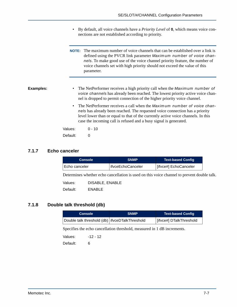
SE/SLOT/#/CHANNEL Configuration Parameters
• By default, all voice channels have a Priority Level of 0, which means voice con-nections are not established according to priority.
NOTE: The maximum number of voice channels that can be established over a link is defined using the PVCR link parameter Maximum number of voice chan-nels. To make good use of the voice channel priority feature, the number of voice channels set with high priority should not exceed the value of this parameter.
Examples: • The NetPerformer receives a high priority call when the Maximum number of voice channels has already been reached. The lowest priority active voice chan-nel is dropped to permit connection of the higher priority voice channel.
• The NetPerformer receives a call when the Maximum number of voice chan-nels has already been reached. The requested voice connection has a priority level lower than or equal to that of the currently active voice channels. In this case the incoming call is refused and a busy signal is generated.
7.1.7 Echo canceler
Determines whether echo cancellation is used on this voice channel to prevent double talk.
7.1.8 Double talk threshold (db)
Specifies the echo cancellation threshold, measured in 1 dB increments.
Values: 0 - 10
Default: 0
Console SNMP Text-based Config
Echo canceler ifvceEchoCanceler [ifvce#] EchoCanceler
Values: DISABLE, ENABLE
Default: ENABLE
Console SNMP Text-based Config
Double talk threshold (db) ifvceDTalkThreshold [ifvce#] DTalkThreshold
Values: -12 - 12
Default: 6
Memotec Inc. 7-7

Analog Voice
7.1.9 Pulse frequency (pps)
Specifies the pulse frequency in pulses per second (pps). This frequency is used for detection purposes.
7.1.10 Activation type
Determines how the voice channel is activated:
• PREDEFINED: The destination unit and port number are preconfigured, using the Remote unit and Remote port number parameters (described on “PRE-DEFINED Activation Type Parameters” on page 7-9). As soon as the device con-nected to the voice channel goes off-hook, the NetPerformer begins a calling procedure with the device at the other site.
This creates a dedicated connection. The two voice channels linked through pre-defined line activation cannot be accessed by any other voice channel in the net-work. Refer to “Predefined Line Activation” on page 1-14.
• SWITCHED: The NetPerformer selects the remote location according to a config-urable Speed dial number that the user enters into the telephone set.
All speed dial numbers are defined in the Voice Mapping Table along with the associated destination unit, extension number and optional dialing sequence to be forwarded to the attached voice equipment.
No predetermined connection is set up between any two ports. Refer to “Switched Line Activation” on page 1-15.
• AUTODIAL: Autodial line activation behaves like a switch that always dials to the same remote unit or set of remote units. The NetPerformer reaches the remote location using a predefined number. This number is permanently configured for the voice port, and does not need to be manually entered. Refer to “Autodial Line Activation” on page 1-17.
Like predefined activation, the NetPerformer begins the calling procedure with the remote site as soon as the device connected to the voice channel goes off-hook.
NOTE: Unlike predefined line activation, inward dialing is allowed on a voice chan-
Console SNMP Text-based Config
Pulse frequency (pps) ifvceDialPulseFrequency [ifvce#] DialPulseFre-quency
Values: 10, 20
Default: 10
Console SNMP Text-based Config
Activation type ifvceActivationType [ifvce#] ActivationType
7-8 Memotec Inc.

SE/SLOT/#/CHANNEL Configuration Parameters
nel configured for AUTODIAL line activation. An AUTODIAL channel is accessible from any other SWITCHED or AUTODIAL analog voice channel in the network.
• BROADCAST: Permits sending a single voice message to multiple destinations using a Frame Relay one-way multicast service. For broadcast activation, the local NetPerformer (or root) transmits the broadcast frames via a special Broad-cast PVC (the Mdlci) to a multicast server. The multicast server then distributes the frames via PVCR PVCs to each remote NetPerformer (or leaf). PVCR PVCs must also be defined for each direct path between root and leaf. For details, refer to “Broadcast Line Activation” on page 1-18.
NOTE: The PREDEFINED and BROADCAST line activation types are not available on a NetPerformer installed with the SIP VoIP licensed software option.
7.1.11 PREDEFINED Activation Type Parameters
The following parameters are required when the Activation type is set to PREDEFINED.
Remote unit
For PREDEFINED Activation onlySpecifies the NetPerformer at the remote site to which voice calls from this voice channel will be directed. Enter the Unit name of the remote NetPerformer unit.
NOTE: The Unit name is defined on the remote unit using the SETUP/GLOBAL sub-menu. Refer to SE/GLOBAL Configuration Parameters in the Quick Configuration fascicle of this document series.
Values: PREDEFINED, SWITCHED, AUTODIAL, BROADCAST
Default: PREDEFINED
Console SNMP Text-based Config
Remote unit ifvceRemoteUnit [ifvce#] RemoteUnit
Values: Maximum 32-character alphanumeric string
Default: NONE
Memotec Inc. 7-9

Analog Voice
Remote port number
For PREDEFINED Activation onlySpecifies the voice channel on the remote NetPerformer to which voice calls from this channel will be directed. Enter the number of the voice channel that is connected to the device you want to reach.
7.1.12 SWITCHED Activation Type Parameters
The following parameters are required when the Activation type is set to SWITCHED.
Hunt Group active
For SWITCHED or AUTODIAL Activation onlyThe NetPerformer can hunt more than one voice channel to place an incoming call, using the Hunt Forwarding feature. The Hunt Group active parameter determines to which Hunt Group this voice channel belongs.
When a switched or autodial call comes in for a particular Hunt Group, the NetPerformer will attempt to connect the call to a voice channel with that Hunt Group active, starting with the oldest unused port. To allow this, a Hunt Group must be targeted in the Voice Mapping Table entry associated with the call, using the Destination extension source and Hunt group parameters.
For details, consult the Hunt Forwarding chapter in the Advanced Voice Features fascicle of this document series.
Delete digits
For SWITCHED Activation onlySpecifies the number of leading dial digits, if any, that will be deleted from a dial string before it is forwarded to the attached voice equipment. This parameter serves to delete the leading dial digits that may be inserted by an attached PBX.
Console SNMP Text-based Config
Remote port number ifvceRemotePort [ifvce#] RemotePort
Values: 1 - 65534
Default: the local voice channel number
Console SNMP Text-based Config
Hunt Group active ifvceHuntGroup [ifvce#] HuntGroup
Values: A, B, C, D, E, F, NONE
Default: NONE
Console SNMP Text-based Config
Delete digits ifvceDelDigits [ifvce#] DelDigits
7-10 Memotec Inc.
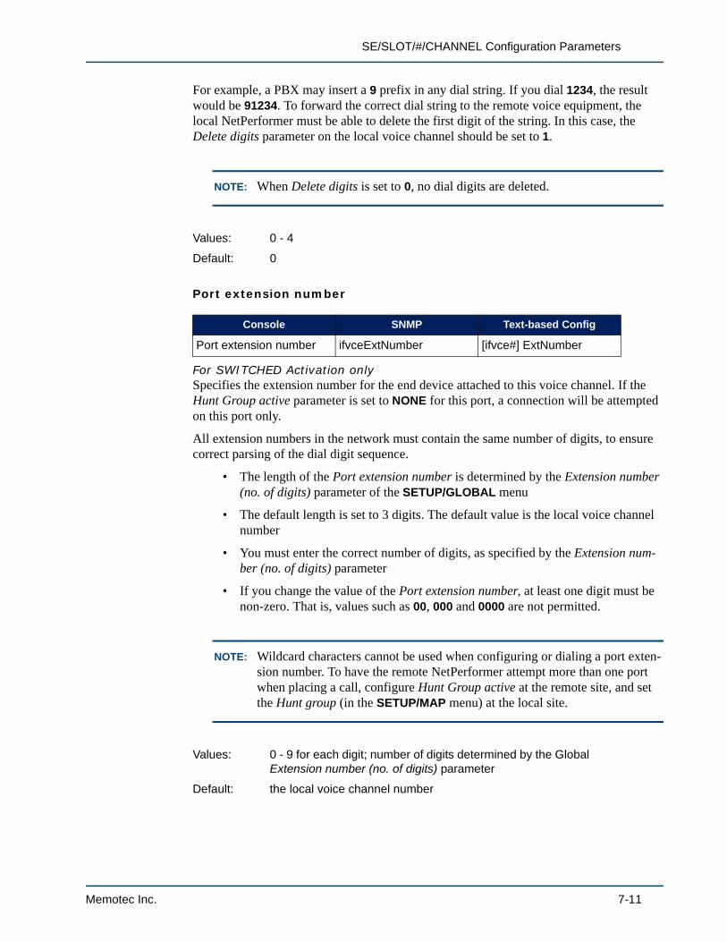
SE/SLOT/#/CHANNEL Configuration Parameters
For example, a PBX may insert a 9 prefix in any dial string. If you dial 1234, the result would be 91234. To forward the correct dial string to the remote voice equipment, the local NetPerformer must be able to delete the first digit of the string. In this case, the Delete digits parameter on the local voice channel should be set to 1.
NOTE: When Delete digits is set to 0, no dial digits are deleted.
Port extension number
For SWITCHED Activation onlySpecifies the extension number for the end device attached to this voice channel. If the Hunt Group active parameter is set to NONE for this port, a connection will be attempted on this port only.
All extension numbers in the network must contain the same number of digits, to ensure correct parsing of the dial digit sequence.
• The length of the Port extension number is determined by the Extension number (no. of digits) parameter of the SETUP/GLOBAL menu
• The default length is set to 3 digits. The default value is the local voice channel number
• You must enter the correct number of digits, as specified by the Extension num-ber (no. of digits) parameter
• If you change the value of the Port extension number, at least one digit must be non-zero. That is, values such as 00, 000 and 0000 are not permitted.
NOTE: Wildcard characters cannot be used when configuring or dialing a port exten-sion number. To have the remote NetPerformer attempt more than one port when placing a call, configure Hunt Group active at the remote site, and set the Hunt group (in the SETUP/MAP menu) at the local site.
Values: 0 - 4
Default: 0
Console SNMP Text-based Config
Port extension number ifvceExtNumber [ifvce#] ExtNumber
Values: 0 - 9 for each digit; number of digits determined by the Global Extension number (no. of digits) parameter
Default: the local voice channel number
Memotec Inc. 7-11

Analog Voice
Fwd digits
For SWITCHED Activation onlySpecifies which dial digits (if any) should be forwarded from the remote unit to the destination device.
• NONE: No dial digits are forwarded to the destination device when a call is initi-ated on this channel.
• ALL: The speed dial number and its associated extended digits are forwarded to the attached equipment. The extended digits may be specified in the Voice Map-ping Table or manually dialed by the user.
• EXT: Only the extended digits string is forwarded to the destination device.
NOTE: The EXT value is not available when the NetPerformer is installed with the SIP VoIP licensed software option.
Use the Fwd digits parameter when the NetPerformer voice channel connects to the trunk side of a PBX or a CO. If an automated answering system responds to the call, the PBX or CO can dial the telephone number to connect to a device on the station side.
NOTE: This parameter does not influence the digits that are sent from the local Net-Performer to the remote NetPerformer. Both the speed dial number and any associated extended digits are sent to the remote site at all times.
If the Fwd digits parameter is set to ALL or EXT, configuration of the following two parameters is also required.
Fwd type
For SWITCHED Activation onlyDetermines how the dial digits are sent to the remote unit for forwarding to the attached device, such as a PBX. They can be sent using pulse dial or Tone. Select PULSE or TONE according to the requirements of the destination user equipment.
Console SNMP Text-based Config
Fwd digits ifvceFwdDigits [ifvce#] FwdDigits
Values: NONE, ALL, EXT
Default: NONE
Console SNMP Text-based Config
Fwd type ifvceFwdType [ifvce#] FwdType
7-12 Memotec Inc.
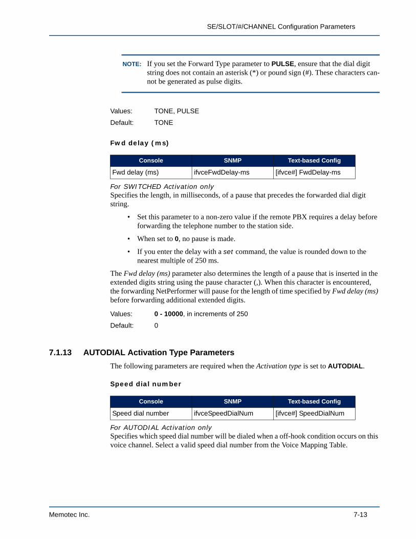
SE/SLOT/#/CHANNEL Configuration Parameters
NOTE: If you set the Forward Type parameter to PULSE, ensure that the dial digit string does not contain an asterisk (*) or pound sign (#). These characters can-not be generated as pulse digits.
Fwd delay (ms)
For SWITCHED Activation onlySpecifies the length, in milliseconds, of a pause that precedes the forwarded dial digit string.
• Set this parameter to a non-zero value if the remote PBX requires a delay before forwarding the telephone number to the station side.
• When set to 0, no pause is made.
• If you enter the delay with a set command, the value is rounded down to the nearest multiple of 250 ms.
The Fwd delay (ms) parameter also determines the length of a pause that is inserted in the extended digits string using the pause character (,). When this character is encountered, the forwarding NetPerformer will pause for the length of time specified by Fwd delay (ms) before forwarding additional extended digits.
7.1.13 AUTODIAL Activation Type Parameters
The following parameters are required when the Activation type is set to AUTODIAL.
Speed dial number
For AUTODIAL Activation onlySpecifies which speed dial number will be dialed when a off-hook condition occurs on this voice channel. Select a valid speed dial number from the Voice Mapping Table.
Values: TONE, PULSE
Default: TONE
Console SNMP Text-based Config
Fwd delay (ms) ifvceFwdDelay-ms [ifvce#] FwdDelay-ms
Values: 0 - 10000, in increments of 250
Default: 0
Console SNMP Text-based Config
Speed dial number ifvceSpeedDialNum [ifvce#] SpeedDialNum
Memotec Inc. 7-13
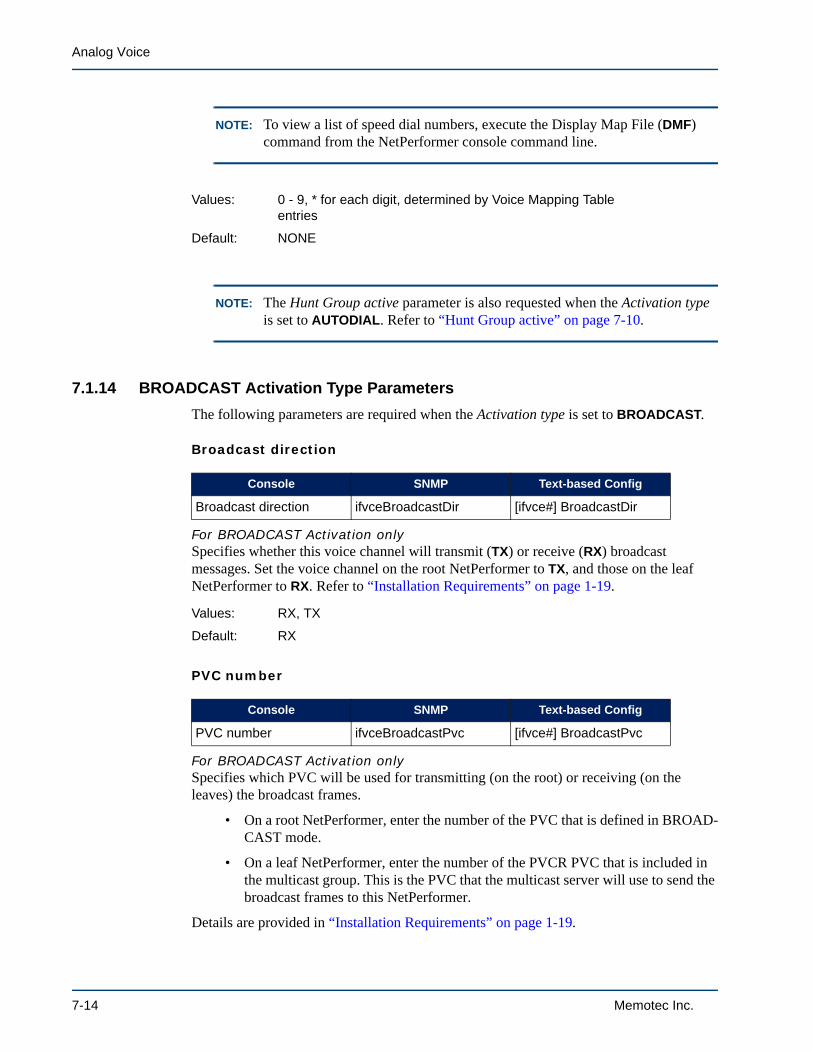
Analog Voice
NOTE: To view a list of speed dial numbers, execute the Display Map File (DMF) command from the NetPerformer console command line.
NOTE: The Hunt Group active parameter is also requested when the Activation type is set to AUTODIAL. Refer to “Hunt Group active” on page 7-10.
7.1.14 BROADCAST Activation Type Parameters
The following parameters are required when the Activation type is set to BROADCAST.
Broadcast direction
For BROADCAST Activation onlySpecifies whether this voice channel will transmit (TX) or receive (RX) broadcast messages. Set the voice channel on the root NetPerformer to TX, and those on the leaf NetPerformer to RX. Refer to “Installation Requirements” on page 1-19.
PVC number
For BROADCAST Activation onlySpecifies which PVC will be used for transmitting (on the root) or receiving (on the leaves) the broadcast frames.
• On a root NetPerformer, enter the number of the PVC that is defined in BROAD-CAST mode.
• On a leaf NetPerformer, enter the number of the PVCR PVC that is included in the multicast group. This is the PVC that the multicast server will use to send the broadcast frames to this NetPerformer.
Details are provided in “Installation Requirements” on page 1-19.
Values: 0 - 9, * for each digit, determined by Voice Mapping Table entries
Default: NONE
Console SNMP Text-based Config
Broadcast direction ifvceBroadcastDir [ifvce#] BroadcastDir
Values: RX, TX
Default: RX
Console SNMP Text-based Config
PVC number ifvceBroadcastPvc [ifvce#] BroadcastPvc
7-14 Memotec Inc.
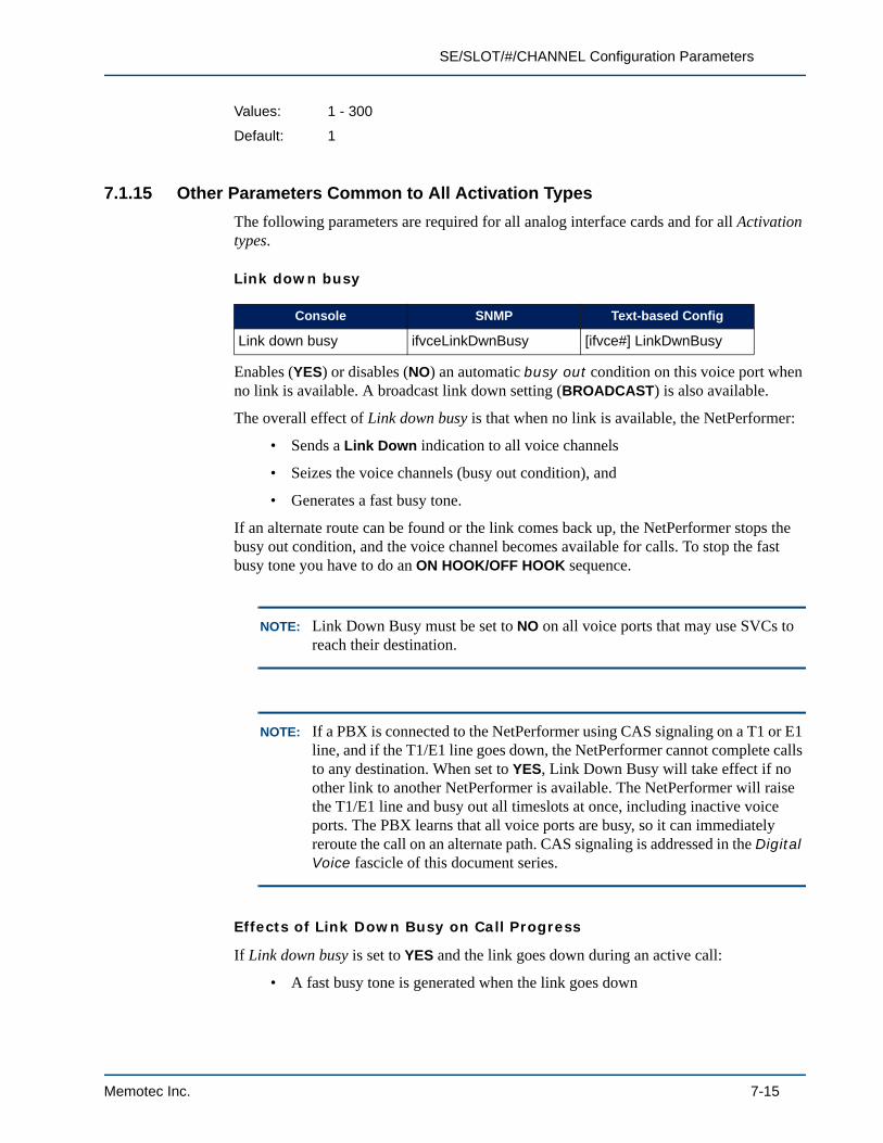
SE/SLOT/#/CHANNEL Configuration Parameters
7.1.15 Other Parameters Common to All Activation Types
The following parameters are required for all analog interface cards and for all Activation types.
Link down busy
Enables (YES) or disables (NO) an automatic busy out condition on this voice port when no link is available. A broadcast link down setting (BROADCAST) is also available.
The overall effect of Link down busy is that when no link is available, the NetPerformer:
• Sends a Link Down indication to all voice channels
• Seizes the voice channels (busy out condition), and
• Generates a fast busy tone.
If an alternate route can be found or the link comes back up, the NetPerformer stops the busy out condition, and the voice channel becomes available for calls. To stop the fast busy tone you have to do an ON HOOK/OFF HOOK sequence.
NOTE: Link Down Busy must be set to NO on all voice ports that may use SVCs to reach their destination.
NOTE: If a PBX is connected to the NetPerformer using CAS signaling on a T1 or E1 line, and if the T1/E1 line goes down, the NetPerformer cannot complete calls to any destination. When set to YES, Link Down Busy will take effect if no other link to another NetPerformer is available. The NetPerformer will raise the T1/E1 line and busy out all timeslots at once, including inactive voice ports. The PBX learns that all voice ports are busy, so it can immediately reroute the call on an alternate path. CAS signaling is addressed in the Digital Voice fascicle of this document series.
Effects of Link Down Busy on Call Progress
If Link down busy is set to YES and the link goes down during an active call:
• A fast busy tone is generated when the link goes down
Values: 1 - 300
Default: 1
Console SNMP Text-based Config
Link down busy ifvceLinkDwnBusy [ifvce#] LinkDwnBusy
Memotec Inc. 7-15

Analog Voice
• If all the links are down, all voice ports are advised with a Link Down indication, and fall into Link Down Busy state. If not all links are down, only PREDEFINED or AUTODIAL ports that use this link will be advised with a Link Down indica-tion, and fall into Link Down Busy state
• After 5 seconds, the NetPerformer verifies if another link is available
• If another link is available, the NetPerformer sends a Link Up indication to all DSPs in Busy handler state that could use that link to reach the destination. (Pre-defined or autodial ports that do not use the alternate link will not receive a Link Up indication.)
• The user must hang up to stop the fast busy tone. A dial tone is restored after an ON HOOK/OFF HOOK sequence
• The user can then redial
• If no other link is available, no Link Up indication is sent to the DSP, and the fast busy tone continues even after an ON HOOK/OFF HOOK sequence.
If Link down busy is set to YES and a new call is attempted while the link is down:
• A dial tone is generated when the user picks up the phone
• The user dials the number, and the NetPerformer sends a Connect Request to try to reach the destination
• Since the link is down, the NetPerformer receives a No Destination indication
• The NetPerformer generates a fast busy tone
• The user must hang up
• After 5 seconds, the NetPerformer verifies if another link is available (a port falls into Link Down Busy state for at least 5 seconds)
• If another link is available, the NetPerformer sends a Link Up indication to the DSP
• Once a link becomes available, the dial tone will be restored after an ON HOOK/OFF HOOK sequence
• The user can then redial.
NOTE: If the link is connected to a PBX that can route calls to an alternate source based on an all busy condition, the PBX will be able to recognize this condi-tion while the link is down and reroute any calls (when Link down busy is set to YES).
If Link down busy is set to NO and the link goes down during an active call:
• No tone is generated. There is silence on the line for as long as the link is down
• If the link comes back up within 10 seconds (before the DSP timeout) the call is reinstated, as long as the user did not hang up
7-16 Memotec Inc.

SE/SLOT/#/CHANNEL Configuration Parameters
• If the link is down for more than 10 seconds, the NetPerformer generates a nor-mal busy tone
• The user must hang up to stop the busy tone. A dial tone is restored after an ON HOOK/OFF HOOK sequence
• The user can then redial.
If Link down busy is set to NO and a new call is attempted while the link is down:
• A dial tone is generated when the user picks up the phone
• The user dials the number, and the NetPerformer sends a Connect Request to try to reach the destination
• Since the link is down, the NetPerformer receives a No Destination indication
• The NetPerformer generates a normal busy tone
• The user must hang up. A dial tone is restored after an ON HOOK/OFF HOOK sequence
• The user can then redial.
NOTE: When Link down busy is deactivated (set to NO) there is no fast busy tone, the link is never seized, and you can always dial out.
NOTE: On analog voice/fax ports there is no busy tone when the Country Code is equal to 100. Code 100, used in Korea, silences the busy tone on an FXS interface. The #6 DTMF tone is generated in the busy state every 30 seconds, regardless of the configuration.
Link Down Busy and NetPerformer Boot-up:
When Link down busy is set to YES and the NetPerformer is booted up, the response of the voice port depends on its activation type:
• PREDEFINED: When the NetPerformer boots up, predefined ports will initially be unable to reach the remote side, since no link is available for the first few sec-onds. A higher level task determines whether the destination is known. Once the destination is recognized, the port is no longer busied out, or seized. A link is now available, and the normal calling procedure can be carried out to the destina-tion.
• SWITCHED: For a switched port, the NetPerformer searches the Voice Mapping Table for the unit names of all valid destinations. As soon as one of these destina-tions is recognized and becomes available, the port is no longer seized. Thus the NetPerformer can attempt a call as soon as one accessible and valid remote site is found. Note that a remote site may be made accessible via a data connection.
Memotec Inc. 7-17
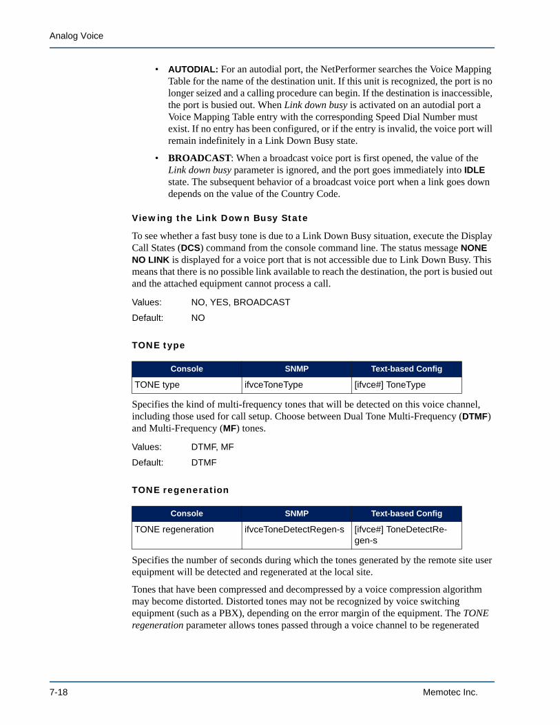
Analog Voice
• AUTODIAL: For an autodial port, the NetPerformer searches the Voice Mapping Table for the name of the destination unit. If this unit is recognized, the port is no longer seized and a calling procedure can begin. If the destination is inaccessible, the port is busied out. When Link down busy is activated on an autodial port a Voice Mapping Table entry with the corresponding Speed Dial Number must exist. If no entry has been configured, or if the entry is invalid, the voice port will remain indefinitely in a Link Down Busy state.
• BROADCAST: When a broadcast voice port is first opened, the value of the Link down busy parameter is ignored, and the port goes immediately into IDLE state. The subsequent behavior of a broadcast voice port when a link goes down depends on the value of the Country Code.
Viewing the Link Down Busy State
To see whether a fast busy tone is due to a Link Down Busy situation, execute the Display Call States (DCS) command from the console command line. The status message NONE NO LINK is displayed for a voice port that is not accessible due to Link Down Busy. This means that there is no possible link available to reach the destination, the port is busied out and the attached equipment cannot process a call.
TONE type
Specifies the kind of multi-frequency tones that will be detected on this voice channel, including those used for call setup. Choose between Dual Tone Multi-Frequency (DTMF) and Multi-Frequency (MF) tones.
TONE regeneration
Specifies the number of seconds during which the tones generated by the remote site user equipment will be detected and regenerated at the local site.
Tones that have been compressed and decompressed by a voice compression algorithm may become distorted. Distorted tones may not be recognized by voice switching equipment (such as a PBX), depending on the error margin of the equipment. The TONE regeneration parameter allows tones passed through a voice channel to be regenerated
Values: NO, YES, BROADCAST
Default: NO
Console SNMP Text-based Config
TONE type ifvceToneType [ifvce#] ToneType
Values: DTMF, MF
Default: DTMF
Console SNMP Text-based Config
TONE regeneration ifvceToneDetectRegen-s [ifvce#] ToneDetectRe-gen-s
7-18 Memotec Inc.

SE/SLOT/#/CHANNEL Configuration Parameters
locally, thus avoiding the possibility of distortion.
• When the TONE regeneration parameter is set to 0, the tone regenerator is always disabled and tones coming from the remote side through the voice chan-nel are decompressed as voice
• When set to 1, the tone regenerator is always on
• Values from 2 to 255 define a specific period, in seconds, during which the tone regenerator is enabled locally.
NOTE: The human voice can produce frequencies which may be interpreted as tones and then regenerated at the remote site if TONE regeneration is always on (set to 1). To avoid tone regeneration during a conversation, it is recommended that this parameter be enabled for a limited amount of time (set to 2 to 255).
TONE ON (ms)
Specifies the duration, in milliseconds, of the multi-frequency tone the NetPerformer uses to generate a single digit.
TONE OFF (ms)
Specifies the duration, in milliseconds, of the silence the NetPerformer adds between multi-frequency tones when generating a dial digit string.
The actual duration of the multi-frequency tone depends to a great extent on the user’s actions, especially for telephones that sound a tone for as long as a number key is pressed. People typically execute a tone duration of 100 - 750 ms, with silence periods of 300 - 1500 ms. Much shorter periods result from automated dialing: typically 60 - 120 ms for tones, with 50 - 150 ms of silence between tones.
Values: 0 - 255
Default: 1
Console SNMP Text-based Config
TONE ON (ms) ifvceToneOn-ms [ifvce#] ToneOn-ms
Values: 30 - 1000 in increments of 10
Default: 100
Console SNMP Text-based Config
TONE OFF (ms) ifvceToneOff-ms [ifvce#] ToneOff-ms
Values: 30 - 1000 in increments of 10
Default: 100
Memotec Inc. 7-19

Analog Voice
Pulse make/break ratio
Specifies the duration, in milliseconds, of the contact (or make) for each digit that is dialed using rotary type dialing. The NetPerformer calculates the break value by subtracting the make value from 100.
For example, the value 34 defines the make/break ratio as 34/66. This value is used in North America, Belgium, Denmark, U.K., France, Portugal and other countries, and is the default Pulse make/break ratio.
When you rotate the dial to a number and release it, a break/contact sequence is repeated once for each digit the dial passes as it returns to the starting position. If, for instance, you dial the number 3, what follows is a 66 ms break, a 34 ms make, a 66 ms break, a 34 ms make, a 66 ms break, then a continuous make (closed loop).
Telephone equipment manufacturers in other countries have implemented other make/break ratios. To ensure correct configuration of the Pulse Make/Break Ratio parameter for your site, contact your local telephone company for the make/break ratio that is currently in use.
Fax relay
Enables or disables handling of fax calls on this voice channel.
• NONE: Fax connections are not detected. Calls are treated as voice only.
NOTE: If a voice call experiences excessive noise, the NetPerformer could interpret it as a fax call. To ensure that all calls will be treated as voice regardless of noise conditions, set this parameter to NONE.
• FAX: Both voice and fax calls are allowed. The NetPerformer will pass fax sig-nals to the remote unit. The switch from voice to fax mode takes place automati-cally when a fax tone is detected.
NOTE: The Fax relay values are different when the NetPerformer is installed with the
Console SNMP Text-based Config
Pulse make/break ratio ifvcePulseMakeBreak-ms [ifvce#] PulseMakeBreak-ms
Values: 30 - 50 in increments of 4
Default: 34
Console SNMP Text-based Config
Fax relay ifvceFaxRelay [ifvce#] FaxRelay
7-20 Memotec Inc.

SE/SLOT/#/CHANNEL Configuration Parameters
SIP VoIP licensed software option:
• NONE: Fax connections are not detected. Calls are treated as voice only.
• T.38: T.38 negotiation is carried out. A SIP Invite message will be sent in T.38 fax mode as well as any voice codecs configured for negotiation (typically G.711 for fax). The unit will accept a T.38 fax call or a SIP Re-invite with one of the codecs configured for negotiation.
For example, if you set the SIP/CODEC NEGO parameters G711 alaw and G711 ulaw to YES, and set the Fax relay parameter on the voice channel to T.38, a SIP Re-invite message will be sent in T.38 fax mode as well as G711 alaw and G711 µlaw. Refer to the chapter Codec Negotiation in the Voice over IP (VoIP) Option fascicle of this document series.
• T.38_SG3: For support of Super G3 faxes. When the NetPerformer detects a Super G3 answering tone it forces a fallback to the G3 standard (at 14.4 Kbps). This permits establishing the connection using T.38 Fax Relay, which requires less bandwidth than Modem Passthru using G.711.
Maximum fax rate
Determines the maximum speed of the fax connection in bits per second. Fax connections can be made at standard speeds from 2400 bps to 14.4 Kbps.
ECM mode
Determines whether Error Correction Mode (ECM) will be used for fax connections on this voice channel. Set to ENABLE for ECM mode.
Values: NetPerformer base product: NONE, FAX
NetPerformer with SIP VoIP option: NONE, T.38, T.38_SG3
Default: NetPerformer base product: FAX
NetPerformer with SIP VoIP option: T.38
Console SNMP Text-based Config
Maximum fax rate ifvceMaxFaxRate [ifvce#] MaxFaxRate
Values: 2400, 4800, 7200, 9600, 12000, 14400
Default: 14400
Console SNMP Text-based Config
ECM mode ifvceFaxEcmMode [ifvce#] FaxEcmMode
Values: DISABLE, ENABLE
Default: DISABLE
Memotec Inc. 7-21

Analog Voice
Modem relay
Enables or disables handling of modem calls on this voice channel, and permits the Modem Passthru function.
• NONE: Modem connections are not detected. Calls are treated as voice only.
• MODEM: Both voice and modem calls are allowed. The NetPerformer will pass modem signals to the remote unit. The switch from voice to modem mode takes place automatically when a modem tone is detected.
• PASSTHRU: For Modem Passthru, which allows a modem connection to be established without using compression, echo cancelling or any other DSP pro-cessing of the traffic stream. The modem signal is sampled using the PCM64K codec algorithm. Modem Passthru simplifies the traffic on a PCM64K connec-tion, permitting higher modem connection speeds.
If the Modem relay parameter is set to MODEM, the following parameter is also required.
Maximum modem rate
Determines the maximum speed of the modem connection in bits per second. Modem connections can be made at standard speeds from 4800 bps to 14.4 Kbps.
V22 Maximum modem relay
Description: V22 Modem relay mode to Point Of Sale (POS) at 1200 and 2400 bps.
Values: NONE, V22 RELAY, V22+POS RELAY, POS RELAY; default value: NONE
V22 Maximum modem rate
Console SNMP Text-based Config
Modem relay ifvceModemRelay [ifvce#] ModemRelay
Values: NONE, MODEM, PASSTHRU
Default: NONE
Console SNMP Text-based Config
Maximum modem rate ifvceMaxModemRate [ifvce#] MaxModemRate
Values: 4800, 7200, 9600, 12000,14400
Default: 14400
Console SNMP Text-based Config
Slot channel x / V22 Modem relay ifvceV22ModemRelay [ifvce #] V22ModemRelay
Console SNMP Text-based Config
Slot channel x / V22 Maximum modem rate ifvceV22MaxModemRate [ifvce #] V22MaxModemRate
7-22 Memotec Inc.

SE/SLOT/#/CHANNEL Configuration Parameters
Description: V22 Maximum modem rate. This parameter is available only when the "V22 Modem relay” parameter is not set to a value different than NONE.
Values: 1200, 2400; default value: 1200
Enable DTMF Detection ON-TIME
The NetPerformer provides transport of DTMF signals. The Enable DTMF Detection ON-TIME parameter determines whether the duration of DTMF ON can be used to filter unwanted DTMF tones during call progress. Set this parameter to YES for DTMF tone filtering.
If the Enable DTMF Detection ON-TIME parameter is set to YES, the following parameter is also required.
DTMF ON-TIME duration (ms)
This parameter specifies the DTMF ON duration, in milliseconds, for filtering unwanted DTMF tones during call progress. To be properly detected by the NetPerformer, DTMF signals must be ON for a duration longer than the value of this parameter.
Redundant channel
Determines whether this channel will be used as a redundant link on a backup system. For details, consult the Redundancy Option fascicle of this document series.
NOTE: This parameter does not appear when the NetPerformer is installed with the SIP VoIP licensed software option, since PowerCell voice is not supported in SIP mode.
Console SNMP Text-based Config
Enable DTMF Detection ON-TIME ifvceEnableDtmfOnTime [ifvce#] EnableDtmfOnTime
Values: NO, YES
Default: NO
Console SNMP Text-based Config
DTMF ON-TIME duration (ms) ifvceDtmfOnTime [ifvce#] DtmfOnTime
Values: 20 - 50
Default: 35
Console SNMP Text-based Config
Redundant channel ifvceRedundantChannel [ifvce#] RedundantChan-nel
Memotec Inc. 7-23

Analog Voice
Egress ANI operation mode
During call setup, the NetPerformer can send locally defined egress ANI digits, or regenerate the ANI digits received from the calling unit. The Egress ANI operation mode parameter determines from which source the ANI digits are taken.
• NONE: The NetPerformer sends only those ANI digits that have been received from the calling unit
• INSERT: The NetPerformer inserts the egress ANI digits that are defined locally on the voice channel, but only if the remote unit did not send any ANI digits
• ALWAYS: The NetPerformer always sends the egress ANI digits that are defined locally on the voice channel, and ignores any ANI digits received from the call-ing unit.
Egress CHANNEL ANI digits
Specifies the ANI digits that will be sent during call setup when the Egress ANI operation mode requires locally defined egress ANI digits (INSERT or ALWAYS setting).
Ingress ANI operation mode
Ingress ANI digits can be defined at both ends of a NetPerformer connection. Typically, ingress ANI is defined at the remote location and is transported to the central site. However, it can operate in the other direction, depending on the direction of the call.
During call setup, the ingress ANI digits are transported from the site where the call originates to the site that receives the call, over the voice channels involved in the
Values: NO, YES
Default: NO
Console SNMP Text-based Config
Egress ANI operation mode
ifvceEgressANIMode [ifvce#] EgressANIMode
Values: NONE, INSERT, ALWAYS
Default: NONE
Console SNMP Text-based Config
Egress CHANNEL ANI digits
ifvceEgressChannelANI-Digits
[ifvce#] EgressChannelA-NIDigits
Values: Maximum 20-character alphanumeric string: 0-9, A-D, *, #
Default: no value
Console SNMP Text-based Config
Ingress ANI operation mode
ifvceIngressANIMode [ifvce#] IngressANIMode
7-24 Memotec Inc.

SE/SLOT/#/CHANNEL Configuration Parameters
connection. The Ingress ANI operation mode parameter determines the source of the ANI digits that are sent with the call:
• NONE: The NetPerformer sends only those ANI digits that have been received from the Telco equipment
• INSERT: The NetPerformer inserts the ingress ANI digits that are defined locally on the voice channel, but only if the Telco equipment did not send any ANI digits
• ALWAYS: The NetPerformer always sends the ingress ANI digits that are defined locally on the voice channel, and ignores any ANI digits received from the Telco equipment.
NOTE: On a NetPerformer installed with the SIP VoIP licensed software option, another mode is available: GATEWAY ID, which inserts the gateway number in the INVITE message during call setup to define the source of the call.
Ingress CHANNEL ANI digits
Specifies the ANI digits that will be sent during call setup when the Ingress ANI operation mode requires locally defined ingress ANI digits (INSERT or ALWAYS setting).
Values: NONE, INSERT, ALWAYS
Default: NONE
Console SNMP Text-based Config
Ingress CHANNEL ANI digits
ifvceIngressChannelANI-Digits
[ifvce#] IngressChan-nelANIDigits
Values: Maximum 20-character alphanumeric string: 0-9, A-D, *, #
Default: no value
Memotec Inc. 7-25

Analog Voice
7.2 FXS Channel ParametersIn addition to the common parameters described earlier, the following parameters are required for configuration of an FXS channel.
Country settings
For an FXS or FXO channelDetermines the ring cadence that will be generated from this voice channel, according to the standards used in various countries. Select the country where the attached telephony device is located.
On an FXS channel you can also set this parameter to CUSTOM, which allows you to customize the ring. If you select this value you will be prompted for all customizable settings.
NOTE: On legacy NetPerformer products this parameter is referred to as Ring type (SNMP: ifvceRingType), and has a shorter list of countries. At the console, enter a question mark (?) after the parameter to view the available choices.
Caller ID (ANI) transmission protocol
For an FXS channel only
Console SNMP Text-based Config
Country settings ifvceRingTypePhoenix [ifvce#] RingTypePhoenix
Values: ARGENTINA, AUSTRALIA, AUSTRIA, BAHRAIN, BELGIUM, BRAZIL, BULGARIA, CANADA, CHILE, CHINA, COLOMBIA, CROATIA, CYPRUS, CZECH REPUBLIC, DENMARK, ESCUADOR, EGYPT, EL SALVADOR, FINLAND, FRANCE, GERMANY, GREECE, HONG KONG, HUNGARY, ICELAND, INDIA, INDONESIA, IRELAND, ISRAEL, ITALY, JAPAN, JORDAN, KAZAKHSTAN, KUWAIT, LATVIA, LEBANON, LUXEMBOURG, MACAO, MALAYSIA, MALTA, MEXICO, MOROCCO, NETHERLANDS, NEW ZEALAND, NIGERIA, NORWAY, OMAN, PAKISTAN, PERU, PHILIPPINES, POLAND, PORTUGAL, ROMANIA, RUSSIA, SAUDI ARA-BIA, SINGAPORE, SLOVAKIA, SLOVENIA, SOUTH AFRICA, SOUTH KOREA, SPAIN, SWEDEN, SWITZER-LAND, SYRIA, TAIWAN, THAILAND, UNITED ARAB EMIR-ATES, UK, USA, YEMEN, CUSTOM
Default: USA
Console SNMP Text-based Config
Caller ID (ANI) transmis-sion protocol
ifvceAnalogCallerID [ifvce#] AnalogCallerID
7-26 Memotec Inc.

SE/SLOT/#/CHANNEL Configuration Parameters
Determines the protocol used for retransmitting the Caller ID (ANI) received from a remote unit. This feature is available on the SDM-9220 and SDM-9230 only. Refer to “Configuring Supplementary Services” on page 2-8.
• Bell 202: The voice channel uses Bell 202 tone modulation at 1200 baud to send the Caller ID. This is the best choice for a unit located in North America, Australia, China, Hong Kong or Singapore.
• V23: Uses CCITT V23 modem tones to send the Caller ID. This is the best choice for a unit located in Europe.
• OFF: No caller ID is transported over the FXS channel.
NOTE: OFF is the default value. You must change this value to allow the FXS channel to retransmit the caller ID.
Billing signals
For an FXS channel onlyDetermines the conditions for generating billing signals on this FXS channel (see “Configuring Supplementary Services” on page 2-8).
• EGRESS: Billing signals are generated if this channel places a call to the phone that is plugged into it
• INGRESS: Billing signals are generated if this channel receives a call from the phone that is plugged into it
• BOTH ENDS: Billing signals are generated if this channel either places or receives a call over the phone that is plugged into it.
• DISABLE: No billing signals are generated on this channel.
First billing signal time (s)
Values: OFF, BELL 202, V23
Default: OFF
Console SNMP Text-based Config
Billing signals ifvceAnalogBillingTones [ifvce#] AnalogBilling-Tones
Values: DISABLE, INGRESS, EGRESS, BOTH ENDS
Default: INGRESS
Console SNMP Text-based Config
First billing signal time (s)
ifvceAnalogFirstBilling-ToneTime
[ifvce#] AnalogFirstBilling-ToneTime
Memotec Inc. 7-27
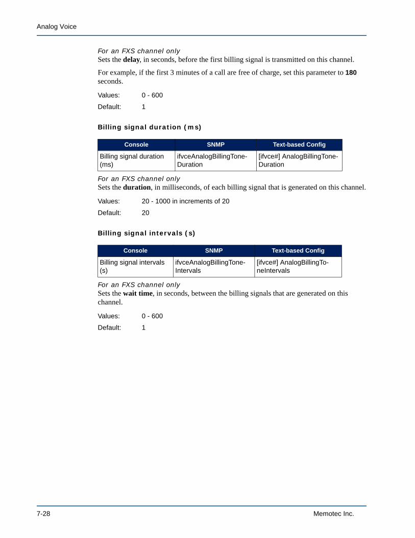
Analog Voice
For an FXS channel onlySets the delay, in seconds, before the first billing signal is transmitted on this channel.
For example, if the first 3 minutes of a call are free of charge, set this parameter to 180 seconds.
Billing signal duration (ms)
For an FXS channel onlySets the duration, in milliseconds, of each billing signal that is generated on this channel.
Billing signal intervals (s)
For an FXS channel onlySets the wait time, in seconds, between the billing signals that are generated on this channel.
Values: 0 - 600
Default: 1
Console SNMP Text-based Config
Billing signal duration (ms)
ifvceAnalogBillingTone-Duration
[ifvce#] AnalogBillingTone-Duration
Values: 20 - 1000 in increments of 20
Default: 20
Console SNMP Text-based Config
Billing signal intervals (s)
ifvceAnalogBillingTone-Intervals
[ifvce#] AnalogBillingTo-neIntervals
Values: 0 - 600
Default: 1
7-28 Memotec Inc.

SE/SLOT/#/CHANNEL Configuration Parameters
7.3 FXO Channel ParametersIn addition to the common parameters described earlier, the following parameters are required for an FXO channel.
FXO seizure delay
For an FXO channel onlyThis parameter determines whether a delay will be added during the call connection process to permit extended digit forwarding before the line is seized. Set FXO seizure delay to ENABLE if extended digit forwarding will be used.
FXO timeout (s)
For an FXO channel onlyThis parameter determines the maximum amount of time, in seconds, that the local voice channel will wait for a fax transmission to begin. If no fax tone occurs by the time the FXO timeout expires, the connection is terminated.
Impedance
For an FXO channel onlyDetermines the frequency and cadence of the ring that will be used on this voice channel. From the list below, select the value that is appropriate to your network. The default value, COUNTRY SPECS COMPATIBLE, means the impedance setting is determined from the current Country settings value (see “Country settings” on page 7-26).
NOTE: On legacy NetPerformer products this parameter can be set to DEFAULT or any multiple of 25 from 500 to 1000. The SNMP equivalent is ifvceImped-
Console SNMP Text-based Config
FXO seizure delay ifvceFxoSeizureDelay [ifvce#] FxoSeizureDelay
Values: DISABLE, ENABLE
Default: ENABLE
Console SNMP Text-based Config
FXO timeout (s) ifvceFxoTimeout-s [ifvce#] FxoTimeout-s
Values: 6 - 99
Default: 30
Console SNMP Text-based Config
Impedance ifvceImpedancePhoenix [ifvce#] ImpedancePhoe-nix
Memotec Inc. 7-29

Analog Voice
ance.
Caller ID (ANI) detection protocol
For an FXO channel onlyDetermines the protocol used for detecting the Caller ID (ANI) received from an FXS voice channel on a remote unit. Caller ID (ANI) can be detected on an FXO interface on the SDM-9220 and SDM-9230 only. Refer to “Configuring Supplementary Services” on page 2-8.
Select the same protocol as that configured on the FXS voice channel with the Caller ID (ANI) transmission protocol (see “Caller ID (ANI) transmission protocol” on page 7-26).
• Bell 202: The voice channel uses Bell 202 tone modulation at 1200 baud to detect the Caller ID. This is the best choice for a unit located in North America, Australia, China, Hong Kong or Singapore.
• V23: Uses CCITT V23 modem tones to detect the Caller ID. This is the best choice for a unit located in Europe.
• OFF: The caller ID cannot be detected on the FXO channel.
NOTE: OFF is the default value. You must change this value to allow the FXO channel to detect the caller ID.
Values: COUNTRY SPECS COMPATIBLE,600 OHMS,900 OHMS,270 OHMS + (750 OHMS || 150 NF),220 OHMS + (820 OHMS || 120 NF),370 OHMS + (620 OHMS || 310 NF),320 OHMS + (1050 OHMS || 230 NF),370 OHMS + (820 OHMS || 110 NF),275 OHMS + (780 OHMS || 150 NF),120 OHMS + (820 OHMS || 110 NF),350 OHMS + (1000 OHMS || 210 NF),0 OHM + (900 OHMS || 30 NF),600 OHMS + 2.16 UF,900 OHMS + 1 UF,900 OHMS + 2.16 UF,600 OHMS + 1 UF,GLOBAL COMPLEX IMPEDANCE
Default: COUNTRY SPECS COMPATIBLE
Console SNMP Text-based Config
Caller ID (ANI) detection protocol
ifvceAnalogCallerID [ifvce#] AnalogCallerID
7-30 Memotec Inc.

SE/SLOT/#/CHANNEL Configuration Parameters
NOTE: The Country settings (on the SDM-9220 or SDM-9230) or Ring type (on leg-acy products) parameter is also required for an FXO channel (see “Country settings” on page 7-26). However, the CUSTOM setting of this parameter is not available for FXO.
Values: OFF, BELL 202, V23
Default: OFF
Memotec Inc. 7-31
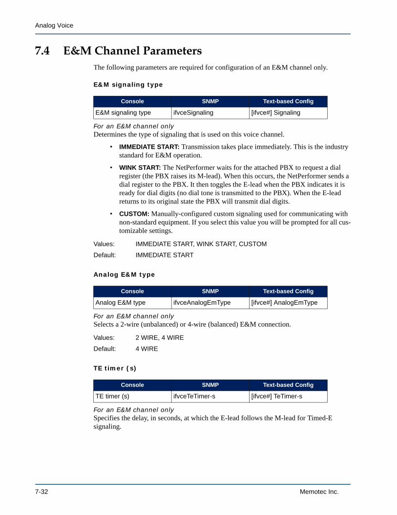
Analog Voice
7.4 E&M Channel ParametersThe following parameters are required for configuration of an E&M channel only.
E&M signaling type
For an E&M channel onlyDetermines the type of signaling that is used on this voice channel.
• IMMEDIATE START: Transmission takes place immediately. This is the industry standard for E&M operation.
• WINK START: The NetPerformer waits for the attached PBX to request a dial register (the PBX raises its M-lead). When this occurs, the NetPerformer sends a dial register to the PBX. It then toggles the E-lead when the PBX indicates it is ready for dial digits (no dial tone is transmitted to the PBX). When the E-lead returns to its original state the PBX will transmit dial digits.
• CUSTOM: Manually-configured custom signaling used for communicating with non-standard equipment. If you select this value you will be prompted for all cus-tomizable settings.
Analog E&M type
For an E&M channel onlySelects a 2-wire (unbalanced) or 4-wire (balanced) E&M connection.
TE timer (s)
For an E&M channel onlySpecifies the delay, in seconds, at which the E-lead follows the M-lead for Timed-E signaling.
Console SNMP Text-based Config
E&M signaling type ifvceSignaling [ifvce#] Signaling
Values: IMMEDIATE START, WINK START, CUSTOM
Default: IMMEDIATE START
Console SNMP Text-based Config
Analog E&M type ifvceAnalogEmType [ifvce#] AnalogEmType
Values: 2 WIRE, 4 WIRE
Default: 4 WIRE
Console SNMP Text-based Config
TE timer (s) ifvceTeTimer-s [ifvce#] TeTimer-s
7-32 Memotec Inc.

SE/SLOT/#/CHANNEL Configuration Parameters
Hoot & Holler application
For an E&M channel onlyA Hoot and Holler connection is a permanent voice connection, that is, one that is always off-hook. The call is always considered up, no matter what signaling information is carried from the user equipment.
• To configure a Hoot and Holler connection on this voice channel, set the Hoot & Holler application parameter to YES. Predefined line activation will be used on both sides of the connection.
• When this parameter is set to NO, the line activation type is determined from the Activation type parameter on this voice channel (see “Activation type” on page 7-8).
Push to Talk application
For an E&M channel onlyEnables a Push To Talk (PTT) application on the E&M interface. PTT is used to key a radio from a remote mobile location to either a control station or another remote location. Refer to “Push To Talk” on page 2-15 for application examples.
In an application involving a fixed control station:
• For the E&M channel to the control station, set the Push to Talk application parameter to PTT CONTROL
• For the E&M channel to the remote location, set Push to Talk application to PTT ANSWER
• The M lead is permanently connected to Signal Ground at the PTT ANSWER side, so that the E&M channel is up at all times.
In an application involving two remote mobile locations:
• Set the Push to Talk application parameter for the E&M channels on both sides of the connection to PTT CONTROL.
Tip: As a general rule of thumb in any PTT application, if the PTT device has a control button, you can set the corresponding E&M channel to PTT CONTROL.
Values: 0 - 255
Default: 0
Console SNMP Text-based Config
Hoot & Holler application ifvceHootHoller [ifvce#] HootHoller
Values: NO, YES
Default: NO
Console SNMP Text-based Config
Push to Talk application ifvcePushToTalk [ifvce#] PushToTalk
Memotec Inc. 7-33

Analog Voice
Set this parameter to DISABLE when Push To Talk is not required on this voice channel.
NOTE: Push To Talk is not available on the voice channel if the Hoot & Holler appli-cation parameter is set to YES.
Values: DISABLE, PTT CONTROL, PTT ANSWER
Default: DISABLE
7-34 Memotec Inc.

8
SE/MAP Configuration ParametersMemotec Inc. 8-1

Analog Voice
8.1 Operation
Specifies the type of operation you would like to execute at the console:
• ADD: To add a new MAP entry to the Voice Mapping Table
• MODIFY: To change an existing MAP entry
• DELETE: To delete a MAP entry from the Voice Mapping Table.
8.2 Entry digits
Defines the digit sequence for the Speed Dial Number. This is the number that the user will dial to reach the desired destination and port. The Entry digits can be any length up to 19 digits; all telephone pad keys can be used.
Use the wildcard character * (asterisk) to represent a range of digits. This is especially useful when designing the voice network for Domain Dialing, discussed in the Advanced Voice Features fascicle of this document series.
Each wildcard character must be replaced with a digit when dialing the number. For example, the speed dial number 1* may be defined for several destinations in Chicago. When dialing to this location, the user can enter 10, 11, 12 and so on up to 19, but cannot enter 1* from the telephone keypad.
8.3 Destination name
Specifies the NetPerformer at the remote site to which the call will be directed. Enter the Unit name of the remote NetPerformer unit.
You can use the * wildcard character, if desired. For example, if you have 3 units at one
Console SNMP Text-based Map
Operation not available not applicable
Values: ADD, MODIFY, DELETE
Default: ADD
Console SNMP Text-based Map
Entry digits not available [map#] MappingEntry
Values: 1 to 8-digit numeric string: 0 - 9, * for each digit
Default: no value
Console SNMP Text-based Map
Destination name not available [map#] UnitName
8-2 Memotec Inc.

SE/MAP Configuration Parameters
site, named BOSTON.1, BOSTON.2 and BOSTON.3, you can refer to all 3 units by setting the Destination name to BOSTON.*, BOSTON*, BOST* or any other shortened form ending in *. When you dial the Entry digits for this MAP entry, all 3 units will be examined for an available voice port.
NOTE: The Unit name is defined on the remote unit using the SETUP/GLOBAL sub-menu. Refer to SE/GLOBAL Configuration Parameters in the Quick Configuration fascicle of this document series.
8.4 Destination extension source
Specifies from which source the NetPerformer will take the destination extension number:
• HUNT: The NetPerformer will use a Hunt Group to complete the call. The call will be connected to the first available voice channel on the destination unit that belongs to a specific Hunt group.
Configure the Hunt Group with the Hunt group parameter, described below.
• USER: The call will be connected to the destination extension number that the user dials (after dialing the Speed Dial Number)
• MAP: The call will be connected to the extension number defined in this MAP entry.
Configure this extension number with the Destination extension parameter, described below.
If the Destination extension source is set to HUNT, the following parameter is also required:
Values: Maximum 32-character alphanumeric string
Default: NONE
Console SNMP Text-based Map
Destination extension source
not available [map#] ExtensionDig-itsSrc
Values: HUNT, USER, MAP
Default: HUNT
Memotec Inc. 8-3

Analog Voice
8.5 Hunt group
For HUNT Destination extension source onlySpecifies the Hunt Group on the destination unit that the NetPerformer will attempt in order to complete the call.
The destination unit will try to complete the call to the lowest numbered voice channel that has the specified Hunt Group active. If this channel is busy, the next voice channel in that Hunt Group will be attempted.
If the Destination extension source is set to MAP, the following parameter is also required:
8.6 Destination extension
For MAP Destination extension source onlyDefines the extension number that will be attempted on the remote NetPerformer. The remote unit will try to connect the call on the voice channel corresponding to the specified extension number.
All extension numbers in the network must contain the same number of digits, to ensure correct parsing of the dial digit sequence.
• The length of the Destination extension is determined by the Extension number (no. of digits) parameter of the SETUP/GLOBAL menu
• The default length is set to 3 digits
• You must enter the correct number of digits, as specified by the Extension num-ber (no. of digits) parameter. If you enter the wrong number of digits, the mes-sage Invalid Extension Number is displayed at the console.
• At least one digit of the Destination extension, must be non-zero. That is, values such as 00, 000 and 0000 are not permitted.
Console SNMP Text-based Map
Hunt group not available [map#] HuntExtension-Digits
Values: A, B, C, D, E, F
Default: A
Console SNMP Text-based Map
Destination extension not available [map#] DestinationExten-sionNb
Values: 0 - 9 for each digit; number of digits determined by the Global Extension number (no. of digits) parameter
Default: no value
8-4 Memotec Inc.

SE/MAP Configuration Parameters
8.7 Extended digits source
Specifies from which source the NetPerformer will take the extended digits that are to be forwarded over this voice channel to the remote side:
• NONE: No source is required for the extended digits. Use this value when no extended digits are to be forwarded to the remote unit (the voice channel Fwd digits parameter is set to NONE).
• USER: The user dials the extended digits that are forwarded to the remote side. The local voice channel will provide a dial tone and wait for the user to dial the extended digits. The user at the local site should dial the appropriate extended digits immediately after the speed dial number (and user-dialed extension num-ber, if required).
- The maximum number of digits that can be entered is determined by the Num-ber of user extended digits parameter in this MAP entry.
- The extended digits terminator, #, can be used to place the call before the maximum number of digits has been dialed and before the Dial timer has expired. Enter the desired digits, followed by #. The # terminator signifies that there are no more extended digits to process, and allows the call to be placed immediately.
• MAP: When placing the call, the local voice channel will use the extended digits defined in the Voice Mapping Table with the Extended digits to forward parame-ter.
When the Extended digits source is set to USER, the following parameter is also required.
8.8 Number of user extended digits
For USER Extended digits source onlyDefines the maximum number of user-dialed extended digits that can be forwarded to the remote unit.
Console SNMP Text-based Map
Extended digits source not available [map#] ExtendedDigitSrc
Values: NONE, USER, MAP
Default: NONE
Console SNMP Text-based Map
Number of user extended digits
not available [map#] UserExtended-Digits
Values: 0 - 27
Default: 0
Memotec Inc. 8-5

Analog Voice
When the Extended digits source is set to MAP, the following parameter is also required.
8.9 Extended digits to forward
For MAP Extended digits source onlyDefines the extended digits sequence that will be forwarded to the remote NetPerformer. Up to 30 digits can be forwarded.
You can include the characters A, B, C and D in the dial string to permit digit mapping that is tone type dependent. A, B and C are valid MF combinations used for ST3P, STP and ST2P, respectively.
NOTE: The global Dial timer parameter, if set to a non-zero value, can be applied to the forwarded digits. If the maximum number of extended digits is not reached, the Extended digits to forward will be sent automatically after the Dial timer expires.
8.10 Use SVC connection
Determines whether the remote NetPerformer will be accessed using SVCs in a Frame Relay network when this speed dial number is used. Set this parameter to YES to activate an SVC connection and continue with SVC configuration at the console. Set it to NO to disable an SVC connection. In this case, a Frame Relay connection must be made using PVCs.
If you are using SVCs, the following conditions must be met:
• The Management interface of the FR-USER port must be set to ANNEX-D. Refer to the WAN/Frame Relay fascicle of this document series
• The Link down busy parameter must be set to NO on all voice channels that may use SVCs to reach their destination.
Console SNMP Text-based Map
Extended digits to for-ward
not available [map#] ExtendedDig-itsString
Values: Maximum 30 digits, 0 - 9, A - D, , (pause), #, *
Default: no value
Console SNMP Text-based Map
Use SVC connection not available [map#] SvcConnection
8-6 Memotec Inc.

SE/MAP Configuration Parameters
• If you are using SVCs, but not fax or modem communications, the Fax Relay and Modem Relay parameters on the voice channel must both be set to NONE. This will prevent the SVCs from taking too much bandwidth.
• If you are using both SVCs and fax or modem communications, set the Maximum fax rate and Maximum modem rate parameters to the maximum speed the voice channel may require for fax or modem communications. This will provide suffi-cient bandwidth to both the SVCs and fax/modem transmissions.
The Link down busy, Fax relay, Modem relay, Maximum fax rate and Maximum modem rate parameters are described in SE/SLOT/#/CHANNEL Configuration Parameters on page 1.
If Use SVC connection is set to YES, the following parameters are also required.
8.11 SVC address type
Determines the type of SVC network addressing that will be used to access the remote NetPerformer. Select either E.164 or X.121. This parameter is required if two Frame Relay ports with different addressing types are available on the same NetPerformer unit.
8.12 SVC network address
Specifies the SVC network address that will be used to access the remote NetPerformer. This may be an E.164 or X.121 address, depending on the value of the SVC address type parameter.
Values: NO, YES
Default: NO
Console SNMP Text-based Map
SVC address type not available [map#] SvcAdressType
Values: E.164, X.121
Default: E.164
Console SNMP Text-based Map
SVC network address not available [map#] SvcNetAddr
Values: Maximum 15 digits, 0 - 9 for each digit
Default: no value
Memotec Inc. 8-7

Analog Voice
8.13 Add another map entry
Determines whether parameter prompts for another MAP entry will be provided at the console. If you select NO, the NetPerformer will save the MAP entry you have just defined, and display the message Saving map entry... at the console.
Console SNMP Text-based Map
Add another map entry not available not applicable
Values: NO, YES
Default: NO
8-8 Memotec Inc.

Index
Numerics6K packetization selection 7-48K packetization selection 7-3
AACELP algorithm 1-3ACELP-CN 7-2ACELP-CN parameters 7-3Activation type 7-8Add another map entry prompt 8-8Analog E&M type 7-32Analog FXO interface card
on signaling engine 1-11Analog FXS interface card
on signaling engine 1-10Analog port
CHANNEL parameters 7-2LINK parameters 6-2
Analog voice connections 1-8Applications
E&M-to-E&M 5-10FXO-to-FXS 5-14FXS-to-FXS 5-8, 5-12Push To Talk 2-15voice broadcasting 1-18
AUTODIAL Activation type parameters 7-13Autodial line activation 1-17
BBackground noise 1-6Billing signal duration (ms) 7-28Billing signal intervals (s) 7-28Billing signal type 6-3Billing signals 7-27Billing signals, on FXS interface 2-8Bit rate 1-3
variable 1-6BROADCAST Activation type parameters 7-14Broadcast direction 7-14Broadcast line activation 1-18Buffering 7-3, 7-4Busy signal 1-13
CCaller ID
on FXO interface 2-12
on FXS interface 2-11Caller ID (ANI) detection protocol 7-30Caller ID (ANI) transmission protocol 7-26Calling procedures 5-8Channel parameters 2-5Codecs 1-3Comfort noise level 7-5Compression 1-5
ratio 1-5variable rate 1-6
Configurationanalog voice connections 2-1voice broadcasting 1-19Voice Mapping Table 3-1
Country settings 7-26Custom signaling 1-7
DDecompression 1-5Delete digits 7-10Destination extension 8-4Destination extension source 8-3Destination name 8-2Dial tone 1-13Double talk threshold (db) 7-7Downloading Map file 3-8DSP 1-3, 1-5, 1-7DTMF ON-TIME duration (ms) 7-22, 7-23DTMF tones
bit rate of 1-6
EE&M
LINK parameters 6-4signaling types 6-4
E&M interfacecalling procedure 5-10usage 1-9
E&M signaling type parameter 7-32E&M type 6-4Echo canceler 7-7Echo canceling 1-7ECM mode 7-21Egress ANI operation mode 7-24Egress CHANNEL ANI digits 7-24Enable DTMF Detection ON-TIME 7-23Entry digits 8-2
Analog Voice 1

Extended digits source 8-5Extended digits to forward 8-6
FFallback 7-3, 7-4Fax application 5-8Fax demodulation 1-6Fax relay 7-20Fax transmissions 5-16First billing signal time (s) 7-27Frame Relay
multicast service 1-18Fwd delay (ms) 7-13Fwd digits 7-12Fwd type 7-12FXO
CHANNEL parameters 7-29, 7-32FXO interface 1-11FXO seizure delay 7-29FXO timeout (s) 7-29FXO-to-FXS application 5-14FXS
CHANNEL parameters 7-26LINK parameters 6-3
FXS interface 1-11calling procedure 5-12
FXS-to-FXS application 5-8, 5-12
GGenerated ring 1-13Generated tones 1-13
HHoot & Holler application parameter 7-33Hoot and Holler application 2-15Hot line 1-14Hunt group 8-4Hunt Group active 7-10
IImpedance parameter 7-29Ingress ANI operation mode 7-24Ingress CHANNEL ANI digits 7-25Initiating a call 5-2Interface types
FXO 1-11FXS 1-11initiating a call 1-20, 5-2terminating a call 1-20, 5-6
KKTS unit
support of 1-2
LLeaf, for voice broadcasting 1-18Line activation 1-14
autodial 1-17broadcast 1-18predefined 1-14switched 1-15
Link down busy 7-15Local inbound voice level (db) 7-6Local outbound voice level (db) 7-6Loop start signaling 1-10
MMAP
parameters 3-2MAP file, uploading 3-8Map parameters
uploading and downloading 3-8Maximum fax rate 7-21Maximum modem rate 7-22Mdlci 1-18Modem Relay 1-4Modem relay 7-22Multicast service 1-18Multi-frequency tones 1-13
NNumber of user extended digits 8-5
OOperation parameter 8-2
PParameter list
6K packetization selection 7-48K packetization selection 7-3Activation type 7-8Add another map entry 8-8Analog E&M type 7-32Billing signal duration (ms) 7-28Billing signal intervals (s) 7-28Billing signal type 6-3Billing signals 7-27Broadcast direction 7-14Caller ID (ANI) detection protocol 7-30Caller ID (ANI) transmission protocol 7-26Comfort noise level 7-5Country settings 7-26Delete digits 7-10Destination extension 8-4
2 Memotec Inc.

Destination extension source 8-3Destination name 8-2Double talk threshold (db) 7-7DTMF ON-TIME duration (ms) 7-22, 7-23E&M signaling type 7-32E&M type 6-4Echo canceler 7-7ECM mode 7-21Egress ANI operation mode 7-24Egress CHANNEL ANI digits 7-24Enable DTMF Detection ON-TIME 7-23Entry digits 8-2Extended digits source 8-5Extended digits to forward 8-6Fax relay 7-20First billing signal time (s) 7-27Fwd delay (ms) 7-13Fwd digits 7-12Fwd type 7-12FXO seizure delay 7-29FXO timeout (s) 7-29Hoot & Holler application 7-33Hunt group 8-4Hunt Group active 7-10Impedance 7-29Ingress ANI operation mode 7-24Ingress CHANNEL ANI digits 7-25Link down busy 7-15Local inbound voice level (db) 7-6Local outbound voice level (db) 7-6Maximum fax rate 7-21Maximum modem rate 7-22Modem relay 7-22Number of user extended digits 8-5Operation 8-2Pcm encoding law 6-2Port extension number 7-11Priority Level 7-6Protocol 7-2Pulse frequency (pps) 7-8Pulse make/break ratio 7-20Push to Talk application 7-33PVC number 7-14Redundant channel 7-23Remote port number 7-10Remote unit 7-9Silence suppression level 7-5Speed dial number 7-13Status 6-2SVC address type 8-7SVC network address 8-7TE timer (s) 7-32TONE OFF (ms) 7-19TONE ON (ms) 7-19TONE regeneration 7-18
TONE type 7-18Use SVC connection 8-6
ParametersACELP-CN 7-3AUTODIAL Activation type 7-13BROADCAST Activation type 7-14CHANNEL 2-5CHANNEL, on analog port 7-2CHANNEL, on FXO 7-29, 7-32CHANNEL, on FXS 7-26LINK, on analog port 6-2LINK, on E&M 6-4LINK, on FXS 6-3MAP 3-2PCM64K 7-5PREDEFINED Activation type 7-9SWITCHED Activation type 7-10
PBXapplication 5-10station-side connection 1-11support of 1-2trunk-side connection 1-9
Pcm encoding law 6-2PCM technology 1-4PCM64K 7-3
parameters 7-5Port extension number 7-11POTS line
support of 1-2PREDEFINED Activation type parameters 7-9Predefined line activation 1-14
calling procedure 5-9configuring 1-14initiating a call 5-2terminating a call 5-6
Priority Level 7-6Protocol parameter 7-2PSTN
support of 1-2Pulse frequency (pps) 7-8Pulse make/break ratio 7-20Push to Talk application 2-15, 7-33PVC number 7-14
RRedundant channel 7-23Remote port number 7-10Remote unit 7-9Ringback tone 1-13Root, for voice broadcasting 1-18
SSignaling
E&M 6-4
Analog Voice 3

tones, bit rate of 1-6Signaling Engine 1-3
custom signaling 1-7voice interfaces 1-8
Silence suppression level 7-5Speed dial number 1-16, 7-13Status parameter 6-2Supplementary services, on analog interface 1-23SVC address type 8-7SVC network address 8-7SVCs, conditions on voice channel 8-6SWITCHED Activation type parameters 7-10Switched line activation 1-14
calling procedure 5-12initiating a call 5-2terminating a call 5-6
TTE timer (s) 7-32Terminating a call 5-6TONE OFF (ms) 7-19TONE ON (ms) 7-19TONE regeneration 7-18TONE type 7-18Tones
audio 1-13physical 1-13
UUploading Map file 3-8Use SVC connection 8-6
VVariable bit rate 1-6Voice broadcasting 1-18
application 1-18Voice codecs 1-3Voice Mapping Table 3-2Voice switching
calling procedure 5-12
WWildcard
in MAP entry 3-3
4 Memotec Inc.

Analog Voice 5

REACH FURTHER. OFFER MORE.
Contact Memotec:
tel.: +1-514-738-4781e-mail: [email protected]
7755 Henri Bourassa Blvd. West Montreal, Quebec | Canada H4S 1P7 www.memotec.com