analog computer simulation of a parasitically … · an analog computer simulation of a...
TRANSCRIPT
N A S A TECHNICAL NOTE - D- -6070
ANALOG COMPUTER SIMULATION OF A PARASITICALLY LOADED ROTATING ELECTRICAL POWER GENERATING SYSTEM
N A T I O N A L A E R O N A U T I C S A N D S P A C E A D M I N I S T R A T I O N W A S H I N G T O N , D. C. NOVEMBER 1970 i
f i
https://ntrs.nasa.gov/search.jsp?R=19710001488 2020-04-23T11:35:09+00:00Z
TECH LIBRARY KAFB, NM
1. Report No.
NASA TN D-6070 "" .
4. Title and Subtitle ANALOG COMp1:
2. Government Accession No.
TER SIMULATION OF A PARA- SITICALLY LOADED ROTATING ELECTRICAL POWER GENERATING SYSTEM
. ." ~~ .
7. Author(s)
Leonard J. Gilbert . - ." .. - - 9. Performing Organization Name and Address
Lewis Research Center National Aeronautics and Space Administration Cleveland, Ohio 44135
. . . . .
12. Sponsoring Agency Name and Address
National Aeronautics and Space Administration Washington, D. C. 20546
~- - . - - - - .
15. Supplementary Notes
. . .. . 3. Recipient's Catalog No.
5. Report Date November 1970
6. Performing Organization Code
~
8. Performing Organization Report No.
E-5616 10. Work Unit No.
120-27 .~
11. Contract or Grant No.
13. Type of Riponand PeriodCovered
Technical Note 14. Sponsoring Agency Code . " . . . . .. -
""
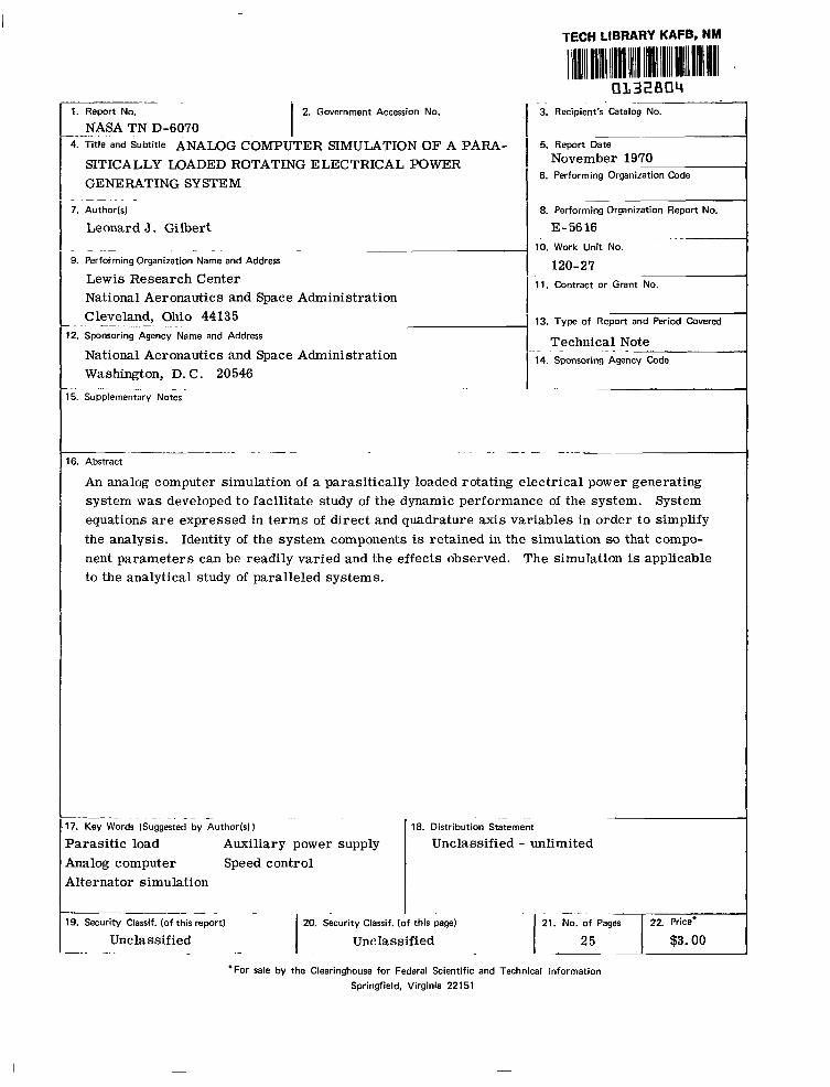
16. Abstract . . ~ " " -
An analog computer simulation of a parasit ically loaded rotating electrical power generating system was developed to facilitate study of the dynamic performance of the system. System equat ions are expressed in t e r m s of direct and quadrature axis var iables in order to s implify the analysis. Identity of the system components is retained in the simulation so that compo- nent parameters can be readily varied and the effects observed. The simulation is applicable to the analytical study of paralleled systems.
___ . - ~. .~ ~" . .
17. Key Words (Suggested by Author(s) j
Parasitic load Auxiliary power supply Analog computer Speed control Alternator simulation
" - ." - 18. Distribution Statement
Unclassified - unlimited
". I 19. Security Classif. (of this report) 20. Security Classif. (of this page)
Unclassified Unclassified _.__~ .. . . " ~ "_ . .
'For sale by the Clearinghouse for Federal Scientific and Technical Information Springfield, Virginia 22151


CONTENTS
Page SUMMARY . . . . . . . . . . . . . . . . . . . . . . . . . . . . . . . . . . . . . . . 1
INTRODUCTION . . . . . . . . . . . . . . . . . . . . . . . . . . . . . . . . . . . . 1
MATHEMATICAL REPRESENTATION O F ELECTRICAL SYSTEM COMPONENTS . 3 System Configuration . . . . . . . . . . . . . . . . . . . . . . . . . . . . . . . . 3 Analytical Approach . . . . . . . . . . . . . . . . . . . . . . . . . . . . . . . . . 4 Assumptions . . . . . . . . . . . . . . . . . . . . . . . . . . . . . . . . . . . . . 4 Alternator . . . . . . . . . . . . . . . . . . . . . . . . . . . . . . . . . . . . . . 5 Useful Load . . . . . . . . . . . . . . . . . . . . . . . . . . . . . . . . . . . . . 7 Speed Controller . . . . . . . . . . . . . . . . . . . . . . . . . . . . . . . . . . 8
Frequency discriminator . . . . . . . . . . . . . . . . . . . . . . . . . . . . . 10 Power amplifier . . . . . . . . . . . . . . . . . . . . . . . . . . . . . . . . . 10 Parasitic load . . . . . . . . . . . . . . . . . . . . . . . . . . . . . . . . . . . 12 Calculation of parasitic power . . . . . . . . . . . . . . . . . . . . . . . . . . 12
Voltage Regulator-Exciter . . . . . . . . . . . . . . . . . . . . . . . . . . . . . 13
COMPUTER REPRESENTATION O F GENERATING SYSTEM . . . . . . . . . . . . 14 Computer Equations . . . . . . . . . . . . . . . . . . . . . . . . . . . . . . . . . 14 Saturation Approximation . . . . . . . . . . . . . . . . . . . . . . . . . . . . . . 14 Simulation Performance . . . . . . . . . . . . . . . . . . . . . . . . . . . . . . 19
CONCLUDING REMARKS . . . . . . . . . . . . . . . . . . . . . . . . . . . . . . . 20
APPENDIX . SYMBOLS . . . . . . . . . . . . . . . . . . . . . . . . . . . . . . . . 21
REFERENCES . . . . . . . . . . . . . . . . . . . . . . . . . . . . . . . . . . . . . 22
iii

ANALOG COMPUTER SIMULATION OF A PARASITICALLY LOADED
ROTATING ELECTRICAL POWER GENERATING SYSTEM
by Leonard J. Gi lber t
Lewis Research Center
SUMMARY
An analog computer representation w a s developed to simulate an alternator with a parasitically loaded speed controller. The simulation permits the study of the dynamic and steady-state behavior of the average values of the electrical characterist ics of the power generating system. A detailed simulation of the electrical performance of a para- sitically loaded power generator had not been developed previously.
The discussion describes a balanced three-phase electrical generating system with balanced loads. The computer representations for all of the electrical components are presented. The identity of the components is retained in the simulation. Speed regula- tion, voltage regulation, load power factor, saturation effects, and amortisseur damp- ing are factors included in the representation. A good correspondence between computer and theoretical performance results, indicating that the simplifying assumptions are ac- ceptable.
The simulation is designed specifically to accommodate the study of paralleled para- sitically loaded alternators. A transformation to direct and quadrature reference axes is used in the analysis.
INTRODUCTION
An analog computer simulation was developed to simulate an electrical generating system consisting of an alternator with a parasitically loading speed controller. The simulation described provides a means of studying the dynamic performance of such an electrical power system. The computer output signals are proportional to average V a l -
ue s of the electrical quantities simulated. Analog computer simulations of a parasit i- cally loaded alternator have been reported by Tew (ref. 1) and Holt (ref. 2). But the de- tailed simulation described here has not been developed previously. In particular the

simulation is designed to be useful for studying the performance of paralleled parasiti- cally loaded generating systems.
Several power generating systems are being developed for space applications (refs. 3 to 5). The systems operate with constant total electrical loads provided by means of parasitic loads. Parasitic loading is an operational mode resorted to when the energy in the system energy source is relatively unlimited. As a consequence of its unlimited energy, the source can be used to control the generating system as well as to supply the electrical requirements of a useful load.
In these parasitically loaded equipments the parasitic load is used to complement the operational or useful load of the alternator so that the sum of all loads on the alter- nator is constant, as illustrated in figure 1. By thus limiting the load torque on the tur-
L
5 n 0
Total alternator power
\ Useful load \
\ \ \ \ /
\ /
Y / \
/ \ \
/ r
/ Parasitic load
/’
7 /’
\
\
’ P i - P[+ Pp
L f 0
Frequency
F igu re L - Schematic diagram of ideal load d i s t r i bu t i on of parasitically loaded alternator.
bine drive, the turbine speed is also limited. The magnitude of the parasitic load re- quired to balance a particular useful load is determined by a controller which senses the electrical frequency of the alternator output. This frequency varies inversely with the useful load applied to the alternator. By appropriate design of the sensing and loading circuits, the parasitic load and its control is made to serve as a speed control.
The parasitic loading control approach is resorted to in closed-cycle space power generating systems in order to avoid rapid control of source energy and precise flow control of the working fluid in the system. Such controls are necessary if the working
2

fluid flow is used to regulate the turbine speed. However, high operating temperatures, the fast reaction speeds required, and the corrosive nature of some working fluids make it undesirable to vary flows continuously for turbine regulation.
In a series of s tudies for the U. S. Ai r Force in 1957 the Energy Conversion Group a t the Massachusetts Institute of Technology developed a simulation of aircraft electrical power generating systems (ref. 6). The approach used here is modeled after that devel- opment. However, in the aircraft systems simulations parasitic loading of the alternator is not a factor, whereas i t is an integral part of some space power systems.
The discussion which follows describes a balanced three-phase alternator with bal- anced loads. The computer representations for all of the electrical subsystem compo- nents are presented, followed by a sample set of displays of characterist ic electrical signals from the simulation.
The specific system simulated is comprised of the following principal components: (1) Turbine driven alternator (2) Voltage regulator and exciter (3) Parasitic load speed controller (4) Useful load
The identification of each component of the system described is retained in the simula- tion. Physical parameters which determine the characterist ics of the system compo- nents are identifiable. Speed regulation, voltage regulation, load power factor, satura- tion effects, amortisseur damping, and saliency are factors included in the representa- tion. The simulation is flexible enough so that it can be augmented to include the dynamics of the drive, and startup and shutdown operation, although this is not done here.
MATHEMATICAL REPRESENTATION OF ELECTRICAL SYSTEM COMPONENTS
System Con f igu ra t i on
The program described simulates the electrical system i l lustrated in f igure 2. A three-phase synchronous alternator is turbine driven with constant power. The electri- ca l output of the alternator is applied to (1) a load representing the desired output, termed the useful load, and to (2) a paral le l load, termed the parasi t ic load. Because of the user's varying demands, the useful load varies. The parasitic load is used to keep the total load constant by balancing it with the input. By keeping the total load power constant the parasitic load functions as a speed control. A voltage regulator- exciter energizes the alternator f ield and regulates the terminal voltage of the alterna- to r as the volt-ampere demand varies.
3

Al ternator
r-" Parasitic load con t ro l l e r
Tu rb ine Al ternator
Parasit ic
con t ro l
Parasit ic load
Figure 2. - Electrical power generating system block diagram.
Analyt ical Approach
In order to study the dynamic performance of the electrical quantit ies of the system the set of simultaneous differential equations which describe the system must be solved. The solution of these equations is extremely complicated unless use is made of a t rans- formation suggested by Blondel's "two-reaction method" and developed by Park (ref. ?). The equations described in this report have been simplified by resolving the variables into components along direct and quadrature axes. This is a standard analytical ap- proach, and discussions of this approach are widely available in modern literature on synchronous machines (ref. 5). However, the use of quadrature reference axes for the var iab les i s a significant feature of this simulation, and the feature which differentiates it from previous simulations of parasitically loaded generating systems.
The simulation was undertaken for use ultimately in studying the dynamic behavior of paralleled parasitically loaded alternators. For paralleled systems information with respect to the relation between voltage and current and rotor is necessary for a com- plete understanding of performance. The use of the dq transformation not only greatly simplifies the solution of the system equations, but also facilitiates the determination of voltage-current phase relations.
When used for the study of two paralleled systems, duplicate equipments described here are required, in addition to transformation and load sharing networks.
Assumpt ions
The following assumptions have been made to facilitate and simplify the analysis:
4

(1) There is sinusoidal air gap flux distribution and sinusoidal winding distribution; that is, the magnetomotive forces in the armature are sinusoidally distributed.
(2) Phase loads are balanced. (3) Eddy current and hysteresis losses can be neglected. (4) Saturation effects take place only in the direct axis circuits. (5) Rotor damping can be represented by including two windings, one in the direct
axis and one in the quadrature axis. (6) Friction and windage losses are neglected. (7) Turbine output power is constant.
Assumptions (1) to (3) are basic assumptions made by R . H. Park ( ref . 7) in the devel- opment of his synchronous machine analysis. That analysis provides the basic circuit equations used to describe the alternator. Assumption (4) reduces the complexity of the simulation. This reduction is desirable and, in view of the alternator performance data usually available, is warranted. The usefulness of the simulation is not substantially re duced by this simplification. Assumption (5) is made because i t is not possible to define a current path through a solid rotor. A fictitious set of damper windings is assumed. The windings are represented in the analysis by one winding in each of the quadrature axes.
Alternator
The conventional generator equations, in terms of direct and quadrature components, as developed by R. H. Park, are listed in this section. They describe the functioning of the circui ts shown in figure 3. These equations are expressed in a per unit system chosen to make all the mutual reactances in any axis, d o r q equal (ref. 8). (All sym- bols are defined in the appendix. )
5
I

I
Quadrature axis
- Direct axis- -
Figure 3. - Schematic diagram of synchronous generator with two damper wind- ings.
The flux linkages in the preceding voltage equations are as follows:
@kq - q m q + *kqL = @mq + Xkqikq -
6

The active and reactive power generated at the terminals of the alternator and the electromagnetic torque developed are given by
P t = v i + v i d td q tq
QC = -vditq + Vqitd
U sef u I Load
The useful loads applied to the alternator consist of series resistance and inductance as illustrated in figure 4. In t e r m s of the direct and quadrature components of current, the load voltages a re expressed as
vd = Rl iz + XL (pil d) - Xz mil
v = R i + X,(piLq) + Xl w i l d q l l q
These equations can be rewritten to eliminate the requirement of an explicit Xz.
c
iZ
i
I.
Figure 4. - Schemati of usefu l load.
7

(This elimination simplifies the application of varied loads in the simulation. ) Dividing each side of the equation by R1 gives
For a given power factor useful load, only R1 need be varied to vary the magnitude of the load.
The currents idl and i a r e components of the total current components itd and ql
i which are determined from the alternator equations. Since the useful load current and the parasit ic load current are assumed to comprise the total al ternator current, tq
itd = il + ipd
itq = il + i Pq
The power dissipated in the useful load is equal to
PI = vdil d + vqil
Speed Controller
The parasitic load speed controller is a control feature which distinguishes this electrical generating system from conventional turboalternator electrical generating systems. Figure 5 is a functional block diagram of the controller. The controller sim-
- = Frequency i D pP Parasitic i A = i P Power discr iminator [Odd ampl i f ier
Figure 5. - Block diagram of parasitically loading speed control ler .
8

ulated is a proportional control: output load current is proportional to the deviation of the input signal frequency from a nominal value no.
by the frequency discriminator. The output of the discriminator, amplified, determines the magnitude of the alternator current through the parasitic load resistor.
When the controller is operating, the frequency deviation is detected and measured
In existing developmental parasitic load speed controllers (SNAP-2, SNAP-8, Bray- ton Power Systems) the control of the current through the load resistor is performed by phase control with saturable reactors or silicon controlled rectifiers (refs. 3 to 5, and 9). Such a phase-controlled current is illustrated in figure 6. Varying the firing angle
c
m c L L
V 3
Figure 6. - Waveshape of phase-controlled current.
(fig. 6) changes the effective value of this nonsinusoidal current. But in addition to changing the value of the current, varying the firing angle also has the effect of changing the phase angle between the applied voltage and the fundamental component of the non- sinusoidal current. The current fundamental lags the voltage as in an inductive circuit. It is this fundamental component of parasitic load current which is the power producing component. Thus, in effect, the variation of parasitic power is the result of a variable inductance. This effect is fully analyzed in reference 10.
9

The computer simulation of the speed controller is based upon this variable induc- tive effect of phase-controlled current.
Frequency discriminator. - .. -. . . - - The frequency discriminator is represented in the sim- ulation as a first degree lag network whose transfer function (ref. 11) is
where
a - Qo A f = f - f - 2 0
O - 2n
(The zero limitation is imposed because a frequency less than fo implies a negative useful load, a nonrealistic quantity. See fig. 1. ) The steady-state characteristic of the discriminator is illustrated in figure ?(a) where iDo is the output current of the discriminator at a frequency fo. Thus
iD = lD . r
+ iDO
Power amplifier. - The power amplifier has also been represented as a f i rs t degree . lag network (ref. 11) whose transfer function is
The steady-state characterist ic of this amplifier is illustrated in figure 7(b); thus
where iAo is the amplifier output current when iD = 0, and is such a value that
iAo = -KAiDO
The combined steady-state characteristic for the discriminator and amplifier is as shown in figure 7(c).
10

\ \ Slope = KD
\ \ \ \-
Af
(a) Characterist ic of frequency discriminator.
‘A
(b) Characteristic of power amplifier.
/ Slope = KAKD
( c ) Combined characteristic of discr iminator and ampl i f ier .
F igu re 7. - Form of steady-state characteristics of simulated speed control ler components.
11

"t
F igu re 8. - Schematic of equivalent parasitic load.
Parasitic load. - In order to simulate the effect of current phase control, the para- sitic load impedance is represented as a series fixed resistance and a variable induc- tance as in figure 8.
I
Calculation of parasitic power. - The computer is programmed to balance the input and output powers of the alternator. The power provided by the turbine is presumed to be constant and is so set. The power is assumed to be completely transferred across the alternator air gap and dissipated in the field, the armature windings, and the useful and parasitic loads; that is,
PIn = Pf $. Pa + Pz f P P
(For convenience Pf and Pa may be considered part of PL . )
made in the useful load, producing a load torque change in the system. The resulting turbine and load torque unbalance produces a speed change. The rotary speed becomes
In demonstrating the performance of the generating system a purposeful change is
P J
The parasitic load speed controller reacts to the speed change until the parasitic load change compensates for the useful load change and the turbine and load torques balance.
12

The power dissipated in the parasitic load resistor is
P = i R 2 P P P
Since R is fixed, in order that the current indicated in this equation equal the para- sitic current generated by the speed control amplifier, the inductance value must vary. The analytical expression used to compute the reactance required to balance the system is
P
P w i P
In t e r m s of the direct and quadrature components, the parasitic current becomes
1 1 Rp 1 .
xP iPd = - -
1 . Vd-" + w - 1
xp P lpd P Pq
and the power dissipated in the parasitic load resistor is
P = v i + v i P d Pd q Pq
Voltage Regulator-Exciter
The model used for the voltage regulator is represented by a lead-lag network whose transfer function is given as
where the error s ignal
13

This model was selected as a representative voltage regulator because it is the voltage control scheme used in an operating developmental generating system, the 400-hertz Brayton Power System (ref. 12). A block diagram illustrating such a regu- lator is shown in figure 9. It represents a stabilized shunt field exciter, sensitive to changes in generator terminal voltage and frequency.
Sensing Stabilized exciter
Figure 9. - Simulated voltage regulator-exciter block diagram.
COMPUTER REPRESENTATION OF GENERATING SYSTEM
Computer Equat ions
The equations presented in the preceding discussion were scaled and converted to a fo rm Convenient fo r application to a PACE 231R analog computer. The simulation in- volved 82 amplifiers, 32 multipliers, and two function generators.
The parameter values used in the simulation are tabulated in table I. The values of this table were obtained from component test results -where available (refs. 13 and 14) - design goals (ref. 15), and estimates of the parameters of a 400-hertz developmental Brayton P3wer System.
Block diagrams of the complete generating system as simulated are included as figures 10 to 12.
Saturat ion Approx imat ion
The nonlinearity of the flux linkage function due to saturation can be approximated by a scheme discussed in reference 16. This scheme approximates the saturation by means of the assumptions that (1) only the direct axis mutual reactance varies with flux, and (2) the direct axis mutual flux is reduced as a resul t of a fictitious "saturation cur- rent" is. This current is described in the following paragraphs.
The alternator no load saturation curve (which is a measurable characterist ic)
14
. .

TABLE I. - PARAMETER VALUE$
[These values were used in simulation runs for which t ransient t races are shown in fig. 14.1
Alternator
'otal inertia, J wmature resistance, Ra Pield resistance, Rf Iirect-axis damper resistance, Rkd hadrature-axis damper resistance, Rks irmature leakage reactance, XaL ?ield leakage reactance, XfL Iirect-axis damper reactance, Xkd $adrature-axis damper reactance, X lirect-axis mutual reactance, Xmd aadrature-axis mutual reactance, xmq
ks
~~
Speed control ~
liscriminator current at fo, iDo 2mplifier gain, KA Discriminator gain, KD Parasitic load resistance, R kmplifier time constant, T ~ , sec Discriminator time constant, T ~ , sec
P
~~
7.28 0.0183
0.00224 0.1450 0. 1450 0. 1280 0. 5770 0. 1158 0. 1680 1.0000 0.6230
0 . 9 5 5 0 ~ 1 0 - ~ 1 . 8 5 0 0 ~ 1 0 ~
0 . 0 4 6 4 ~ 1 0 - ~ 0. 5556 0.03 10 0.0050
Voltage regulator-exciter
Gain, K1 Gain, K 73. F Reference voltage, vRef 0.099E Time constant, T ~ , sec 0.09: Time constant, T ~ , sec 1. 54(
Base values I
-
t
I
I
> 1 - - 5 1 3 3
Power, PInO, kW 5 Phase voltage, vtO, V 120 Time base, cy 100 aper unit values unless otherwise indicated.
..
Field current, ifo, A Field voltage, vfO, V Frequency, f , Hz
2. f 576( 40(
Phase current, itO, A I 41.
15

I I 1 1 1 I l l I I
Figure 11. - Block diagram of frequency discriminator and amplifier.
16

r
, , Rl
+ L
Figure 12. - Block diagram of useful and parasitic loads.
shows that the terminal voltage is a nonlinear function of field current (fig. 13(a)); that is,
where Xmd(if) is the nonlinear factor. The assumption that under load the same func- tional relation exists between current and reactance makes
If the saturation curve under load is plotted as shown in figure 13(b), then
q m d
xm dO (if - itd + ikd) = ___ f($md)
17

‘f
(a) Alternator no load characteristic.
(b) Saturation curve replotted to show is.
Figure 13. - Use of saturation curves to determine saturation current.
where the nonlinearity is included in the term f(Qmd). This term is called the satura- tion current is. Its value can be determined from the saturation curve as follows:
Qmd i = (i - itd + ikd) - ~
xm dO s f
Then

1
J
Figure 14. - Simulation transient characteristics resulting from step changes in useful load, Useful load power factor = 0. 7 (lagging).
In the simulation this saturation effect is included by using a nonlinear function generator to generate is as a function of Qmd.
Simulation Performance
In order to demonstrate the performance of the simulation, recorder traces of several sample character is t ics resul t ing f rom s tep changes in useful load are presented in figure 14.
The characterist ics display the expected theoretical performance of parasitically loaded electrical power generating system. Upon the step removal of the useful load the terminal voltage increases suddenly, returning to a steady-state value with a t rans- ient typical of a lead-lag regulator characteristic. The slight increase in the useful load power immediately following the step change is the result of the voltage pulse from unloading of the alternator. The freq.uency increases exponentially to a steady-state
19
value, and displays the characteristic of an over-damped system. Similarly, the para- sitic load power increases in an exponential manner governed by the inductive nature of the parasitic load controller. The total power load (which in this case includes the arm- ature and f ield losses), after its transient dip, returns to its fixed steady-state value.
When this load change is reversed, that is, upon the step application of essentially a per unit useful load, the displayed characteristics change in the opposite direction. There is one significant difference because (in this instance) the added useful load is in- ductive (0.7 lagging power factor). The additional impedance to current change is evi- dent in the transient characteristics.
CONCLUDING REMARKS
The simulation developed herein permits dynamic analysis of parasitically loaded electrical power generating systems. Analysis of such regulated power systems without resor t to computers is prohibitive because of the complexity of the equations describing the systems. Used properly the simulation can be a valuable tool in the analysis of con- templated designs or the improvement of existing designs. With the computer, steady- state and transient stability can be observed as system conditions and parameters are changed.
The simulation described can be altered and expanded to include additional opera- tional factors (such as variable turbine power) and more refined models of the compo- nents. With the addition of load-sharing circuits the simulation can be used for the study of paralleled alternators.
Lewis Research Center, National Aeronautics and Space Administration,
Cleveland, Ohio, June 30, 1970, 120-27.
20

f
i
i'
J
K
P
P
Q R
T
V
X
a
e 7
+ 52
w
APPENDIX - SYMBOLS
(Unless otherwise indicated, all quantities are expressed as per unit. )
frequency, Hz (also functional nota- tion)
current
current (variable component)
total inertia
gain
power
differential operator d/dt
reactive volt-amperes
res is tance
torque
voltage
reactance (inductive)
t ime base
power factor angle
time constant
flux linkage
electrical frequency, rad/sec
electrical frequency
Subscripts:
A
a
D
d
e
f
In
k
L
1
m
P
q
Ref
S
T
t
0
amplifier
a rmature
discriminator
direct axis
e r r o r
field
input
damper
leakage
useful load
mutual
parasitic load
quadrature axis
reference
saturation
turbine
total or terminal
(zero) base or nominal value
2 1
REFERENCES
1. Tew, Roy C. ; Gerchman, Robert D. ; and Hurrell , Herbert G. : Analog-Computer Study of Parasitic-Load Speed Control for Solar-Brayton System Turboalternator. NASA TN D-3784, 1967.
2. Holt, Hugh M. : A Parasitic Load Speed Control for Dynamic Space Power Systems. M. S. Thesis, Univ. of Virginia, 1969.
3. Klann, John L. : 2 to 10 Kilowatt Solar or Radioisotope Brayton Power System. In- tersociety Energy Conversion Engineering Conference. Vol. I. IEEE, 1968, pp. 407-415.
4. Thur, George M.: SNAP-8 Power Conversion System Assessment. Intersociety Energy Conversion Engineering Conference. Vol. 1. IEEE, 1968, pp. 329-337.
5. Ingle, B. D. ; and Corcoran, C. S. : Development of a 1200-Hertz Alternator and Controls for Space Power Systems. Intersociety Energy Conversion Engineering Conference. Vol. 1. IEEE, 1968, pp. 438-447.
6. Riaz, M. ; and Smith, P. E . , Jr. : A Performance Study of an Aircraft A-C Gener- ating System Using Analog Computation. Tech. Note 57-160, Wright Air Develop- ment Center, 1957.
7. Park, R. N. : Two-Reaction Theory of Synchronous Machines Generalized Method of Analysis. AIEE Trans. , vol. 48, 1929, pp. 716-727.
8. White, David C. ; and Woodson, Herbert H. : Electromechanical Energy Conversion. John Wiley & Sons, Inc. , 1959.
9. Dauterman, W. E. ; and Viton, E. J. : SNAP 11 Rotational Speed Control. IRE Trans. on Nucl. Sci., vol. NS-9, no. 1, Jan. 1962, pp. 151-157.
10. Gilbert, Leonard J. : Reduction of Apparent-Power Requirement of Phase- Controlled Parasitically Loaded Turboalternator by Multiple Parasitic Loads. NASA TN D-4302, 1968.
11. Word, John L. ; Fischer , Raymond, L. E. ; and Ingle, Bill D. : Static Parasit ic Speed Controller for Brayton-Cycle Turboalternator. NASA TN D-4176, 1967.
12. Bollenbacher, Gary; Edkin, Richard A. ; and Perz, Dennis A. : Experimental Eval- uation of a Voltage Regulator - Exciter for a 15 Kilovolt-Ampere Brayton Cycle Alternator. NASA TN D-4697, 1968.
13. Valgora, Martin E. ; and Perz, Dennis A. : Steady-State Electrical Performance of a 400-Hertz Brayton Cycle Turboalternator and Controls. NASA TN D-5658, 1970.
22
14. Edkin, Richard A. ; Valgora, Martin E. ; and Perz, Dennis A. : Performance Characterist ics of 15 kVA Homopolar Inductor Alternator for 400 Hertz Brayton Cycle Space-Power System. NASA TN D-4698, 1968.
15. Dryer, A. M. ; Kirkpatrick, F. M. ; Russell, E. F.; Winsatt, J. M. ; and Yeager, L. J. : Alternator and Voltage Regulator-Exciter for a Brayton Cycle Space Power System. Vol. 1 - Alternator and Voltage Regulator-Exciter Design and Development. Rep. GE-A69-003, General Electric Co., May 1969.
16. Boffi, L. V. ; Riaz, M. ; and Smith, P. E . , Jr. : Analog Computer Repl.esenta- tions of Aircraft Parallel Alternating-Current Generating Systems. Tech. Note 56-384, Wright Air Development Center, 1956.
NASA-Langley, 1970 - 3 E- 56 16 23

NATIONAL AERONAUTICS AND SPACE ADMINISTRATION WASHINGTON, D. C. 20546
OFFICIAL BUSINESS FIRST CLASS MAIL
NATIONAL AERONAUTICS ANI POSTAGE AND FEES PAID
SPACE ADMINISTRATION
02u 001 2 8 51 30s 70286 00903 A I R FORCE WEAPONS L A B O R A T O R Y /WLcL/ K I R T L A I V D AFB, NEW M E X I C O 37117
A T T E, LOU BOdPAN, C H I E F , T E C H o L I B R A R Y
POSTMASTER: If Undeliverable (Section 158 Postal Manual) Do Not Return
"The aerotaalctical and space activities of the United States shall be condzlcted so as t o contribute . . . to the expansion of hzman knowl- edge of phenomena i g z the atmosphere agzd space. The Administration shall provide foY zhe widest practicable and appropriate dissemination of information concer@zg its nctizlities and t h e ~ e s z l t s thereof."
-NATIONAL AERONAUTICS AND SPACE ACT OF 1958
NASA SCIENTIFIC +AND TECHNICAL PUBLICATIONS
TECHNICAL REPORTS: Scientific and TECHNICAL TRANSLATIONS: Information technical information considered important, published in a foreign language considered complete, and a lasting contribution to existing to merlt NASA distribution in English. knowledge.
/
SPECIAL PUBLICATIONS: Information TECHNICAL NOTES: Information less broad in scope but nevertheless of importance as a contribution to existing knowledge.
TECHNICAL MEMORANDUMS: Information receiving limited distribution because of preliminary data, security classifica- tion, or other reasons.
CONTRACTOR REPORTS: Scientific and technical information generated under a NASA contract or grant and considered an important contribution to existing knowledge.
derived from or of value to NASA activities. Publications include conference proceedings, monographs, data compilations, handbooks, sourcebooks, and special bibliographies.
TECHNOLOGY UTILIZATION PUBLICATIONS: Information on technology used by NASA that may be of particular interest in commercial and other non-aerospace applications. Publications include Tech Briefs, Technology Utilization Reports and Notes, and Technology Surveys.
Details on the availability of these publications may be obtained from:
SCIENTIFIC AND TECHNICAL INFORMATION DIVISION
NATIONAL AERONAUTICS AND SPACE ADMINISTRATION Washington, D.C. 20546