anali of rauli raure roagaion in tougne ominan i coniering
TRANSCRIPT

Amirkabir Journal of Civil Engineering
Amirkabir J. Civil Eng., 52(2) (2020) 123-130DOI: 10.22060/ceej.2018.14498.5673j
Analysis of Hydraulic Fracture Propagation in Toughness Dominant with Considering Fluid Viscosity and Inertia Parameters Interaction: Higher Order Terms
A. Asgari1*, A. Golshani2 1 Department of Engineering and Technology, University of Mazandaran, Babolsar, Iran2 Department of Civil and Environmental Engineering, Tarbiat Modares University, Tehran, Iran
ABSTRACT: In the process of hydraulic fracture, various physical parameters such as; viscosity, inertia of fluid and toughness of rock do not influence the fracture propagation identically, and it is probable that one or more of the parameters be more pronounced. Therefore, it may persuade one special regime which is named base on the dissipation of energy. In an impermeable rock, the two limiting regimes can be identified with the dominance of one or the other of the two energy dissipation mechanisms corresponding to extending the fracture in the rock and to flow of viscous fluid in the fracture, respectively. In the viscosity-dominated regime, dissipation in extending the fracture in the rock is negligible compared to the dissipation in the viscous fluid flow, and in the toughness-dominated regime, the opposite holds. It is supposed that the flow of incompressible fluid in the fracture is unidirectional and laminar. Besides, the fracture is fully fluid-filled at all times and fracture propagation is described in the framework of linear elastic fracture mechanics (LEFM). The contribution of this research is a detailed study of the evaluation parameters’ effects on the propagation of hydraulic fracture an impermeable brittle rock. Here, the modified perturbation method suggested for evaluating fluid viscosity and inertia parameters interaction (FVII). The proposed method provides a good estimate of the solution in the wide range of the viscosity/inertia parameters because of the coexistence of both small parameters in the governing equations. The results showed that considering the FVII reduce the length of the crack, and the crack length decreases with increasing viscosity parameter, and the decreasing trend will be intensified by increasing the inertia of fluid. On the other hand, the effects of fluid viscosity in the hydraulic fracture injection process are more pronounced than the effects of the inertia parameter on the assumption of a laminar flow. Neglecting the effect of the FVII result in a significant error. These errors continue to increase with the increase, and may reach about 300%. At last, the results are compared with the available references, which confirms the logical process.
Review History:
Received: 2018-05-27Revised: 2019-02-22Accepted: 2019-09-18Available Online: 2018-09-15
Keywords:
Hydraulic fracture
Interaction effect
Inertia
Viscosity
Modified perturbation method
123
*Corresponding author’s email: [email protected]
Copyrights for this article are retained by the author(s) with publishing rights granted to Amirkabir University Press. The content of this article is subject to the terms and conditions of the Creative Commons Attribution 4.0 International (CC-BY-NC 4.0) License. For more information, please visit https://www.creativecommons.org/licenses/by-nc/4.0/legalcode.
1- INTRODUCTIONThe best references for the technical skills and practical
background of hydraulic fracturing treatments in the oil and gas industry are the compilations provided by Gidley et al [1], and Economides and Nolte [2]. In the last decades, researchers have made an effort to model the process of hydraulic fracturing both analytically and numerically; see Reference [3] for some further references. Some other investigation in the areas of analytical models for hydraulic fracturing are briefly noted in the following:
Spence and Sharp [4] presented a self-similar solution for a KGD crack propagating in an elastic, impermeable medium with finite toughness. Their model combines lubrication theory to model the flow incompressible viscous fluid in the fracture; the linear elasticity theory in plane strain to model the crack opening due to a given pressure distribution; and the fracture mechanics theory by using square-root tip
asymptote for the crack opening and propagation condition controlled by the stress intensity factor. Following Spence and Sharp’s method [4], Carbonell [5] have developed a self-similar solution for the asymptotic case of zero toughness. This solution is based on the so-called SCR [6] tip asymptote which describes the asymmetric behavior of opening and pressure at near the tip of the crack tip. The numerical method originally proposed by Spence and Sharp [4] and later in refined form by Adachi [7] and Asgari [8] is appropriate to find the solution in this intermediate regime, where the effects of fluid viscosity and rock toughness are of the same order. Ongoing, many researchers, in order to simplify the analysis of the problem, consider it as one of toughness regime (waste of energy due to toughness or hardness of the rock) e.g. Garagash (2000) [9] or viscosity-dominated (loss of energy due to high viscosity of the fluid) [10, 11]. Huang et al. [12] examined the propagation of a plane-strain fracture under condition of zero-viscosity of fluid. They have improved a self-similar solution under assumption of the dominance
A. Asgari1 and A. Golshani , Amirkabir J. Civil Eng., 52(2) (2020) 123-130, DOI: 10.22060/ceej.2018.14498.5673
124
of the fluid inertia forces as compared to the viscous drag. Some other researchers [4, 13, 14] have assumed that the fluid inertia effects on either fracture propagation or the fluid flow in the crack are negligible (even under conditions when fluid viscosity vanishes) and the fluid flow can be modeled by the lubrication theory [15]. Garagash (2006) [16] applied an explicit solution for a fracture propagating in the toughness-dominated regime when the energy dissipated in the viscous fluid flow inside the fracture is negligibly small compared to the energy expended in fracturing the solid medium. It was also shown that the established method of asymptotic expansion in the small parameter is equally applicable to study other small effects (e.g., fluid inertia) on the otherwise toughness-dominated solution. Consequently, Garagash [16] presented the scaling for the fracture propagation driven by inertial, unidirectional flow of viscous fluid, and evaluate the effect of inertia. Garagash [16] examined the inertia and viscosity parameter effects separately in the other words without considering FVII effect on the hydraulic fracture process. In this paper, the net pressure in the fracture, the crack opening, and the fracture half-length are obtained with considering the FVII effect on the toughness-dominated solution. The modified perturbation method is proposed here for evaluating the FVII effects on the otherwise toughness-dominated solution of a plane-strain hydraulic fracture.
2- MATHEMATICAL FORMULATION 2-1- Problem definition
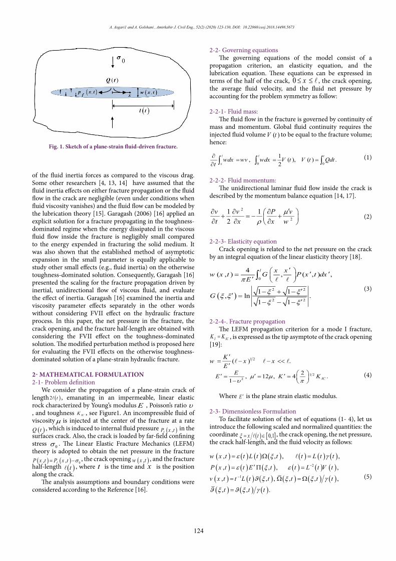
We consider the propagation of a plane-strain crack of length ( )2 t , emanating in an impermeable, linear elastic rock characterized by Young’s modulus E , Poisson’s ratio υ, and toughness ICK , see Figure1. An incompressible fluid of viscosityµ is injected at the center of the fracture at a rate ( )Q t , which is induced to internal fluid pressure ( ),fP x t in the
surfaces crack. Also, the crack is loaded by far-field confining stress 0σ . The Linear Elastic Fracture Mechanics (LEFM) theory is adopted to obtain the net pressure in the fracture( ) ( ) 0, ,fP x t P x t σ= − , the crack opening ( ),w x t , and the fracture
half-length ( )t , where t is the time and x is the position along the crack.
The analysis assumptions and boundary conditions were considered according to the Reference [16].
2-2- Governing equationsThe governing equations of the model consist of a
propagation criterion, an elasticity equation, and the lubrication equation. These equations can be expressed in terms of the half of the crack, 0 x≤ ≤ , the crack opening, the average fluid velocity, and the fluid net pressure by accounting for the problem symmetry as follow:
2-2-1- Fluid mass:The fluid flow in the fracture is governed by continuity of
mass and momentum. Global fluid continuity requires the injected fluid volume ( )V t to be equal to the fracture volume; hence:
0 0
1, ( ), ( ) .2
t
xwdx wv wdx V t V t Qdt
t∂
= = =∂ ∫ ∫ ∫
(1)
2-2-2- Fluid momentum:The unidirectional laminar fluid flow inside the crack is
described by the momentum balance equation [14, 17].
2
21 12
µρ
′∂ ∂ ∂ + = − + ∂ ∂ ∂ v v P vt x x w
(2)
2-2-3- Elasticity equationCrack opening is related to the net pressure on the crack
by an integral equation of the linear elasticity theory [18].
( )
0
2 2
2 2
4( , ) , ( , ) ,
1 1, ln .1 1
′ ′ ′= ′
′− + −′ =′− − −
∫
l x xw x t G P x t dxE
G
π
ξ ξξ ξ
ξ ξ
(3)
2-2-4-. Fracture propagationThe LEFM propagation criterion for a mode I fracture,
I ICK K= , is expressed as the tip asymptote of the crack opening [19]:
1 2( ) .′
= − − <<′
Kw x xE
(4)1 22
2, 12 , 4 .1
′ ′ ′= = = − IC
EE K Kµ µυ π
Where E ′ is the plane strain elastic modulus.
2-3- Dimensionless FormulationTo facilitate solution of the set of equations (1- 4), let us
introduce the following scaled and normalized quantities: the coordinate ( ) [ ]0,1x tξ = ∈
, the crack opening, the net pressure, the crack half-length, and the fluid velocity as follows:
( ) ( ) ( ) ( ) ( ) ( ) ( )( ) ( ) ( ) ( ) ( ) ( )( ) ( ) ( ) ( ) ( ) ( )( ) ( ) ( )
2
1
, , , ,
, , , ,
, , , , , ,
, , .
w x t t L t t t L t t
P x t t E t t L t V t
v x t t L t t t t t
t t t
ε ξ γ
ε ξ ε
ϑ ξ ξ ξ γ
ϑ ξ ϑ ξ γ
−
−
= Ω =
′= Π =
= Ω = Ω
=
(5)
Figure 1. Sketch of a plane-strain fluid-driven fracture.
Fig. 1. Sketch of a plane-strain fluid-driven fracture.

125
A. Asgari1 and A. Golshani , Amirkabir J. Civil Eng., 52(2) (2020) 123-130, DOI: 10.22060/ceej.2018.14498.5673
It is noted that “bar sign” corresponds to the normalized quantities.
Using the above transformations, Equations (1- 4) can be re-written in an alternative form as follows:
• Fluid mass1 1
20
1
1d , d ,2
d .
T
T
tV tLV L
t
ξ
ξ
ξ ξ ϑ ξγ
γ ξ ξγ ξ
Ω + Ω+Ψ = Ω Ω =
∂ΩΨ = Ω+ Ω− ∂
∫ ∫
∫
(6)
• Fluid momentum
2ñ m 2=G 1 1 G ,
1 .
T
T
tLL
t t
ξ ϑ ϑ ϑγ ϑξ ϑ ξ ξ
γ ξ ϑ ϑγ ϑ ξ ϑ
∂Π ∂ ∂− − − + +Φ + ∂ ∂ ∂ Ω
∂Φ = − + ∂
(7)
• Elasticity equation and fracture propagation
( ) ( ) ( ) ( )
( )
11
1 2 1 2k1
4, L , , , d ,
lim 1 G .
t t G tξ
ξ
ξ ξ ξ ξ ξ ξπ
ξ γ
−
− −
→
′ ′ ′Ω = Π = Π
− Ω =
∫
(8)
The terms TΦ and TΨ are time-transient parts in the continuity Equation 6 and momentum Equation 7, respectively.
Also, three dimensionless parameters kG , ìG , and ñG in
Equations 7 and 8 are expressed as:
3 2 6 4
kì ñ 3 2G ,G ,G .K L L LE V E tV E t V
µ ρ′ ′= = =
′ ′ ′
(9)
For more expressions of these dimensionless parameters in the three scaling, identified as the toughness scaling kG 1=, the viscosity scaling ìG 1= , and the inertia scaling ñG 1= , refer to [16].
Consequently, tV V and tL L in continuity Equation 6 and momentum Equation 7 are the corresponding constant exponents, and the time derivative operator to ( ).t t∂ ∂ in Equations 6 and 7 can be replaced by
k mk m
k k m m
G GG GG G G Gt tt
t ∂ ∂ ∂
= + ∂ ∂ ∂
(10)
Where over dot denotes the differential with respect tot .
3- BASIC IDEAIn this work, the modified perturbation method is suggested
to find an approximate solution to the problem of plane-strain hydraulic fracture propagating in an impermeable brittle rock. The perturbation method is applicable if dimensionless parameters can be considered as “small” quantities. Since there are three different dimensionless parameters kG , ìG and
ñG , thus we assume:
4
( )( )1 2
1 2
1 21,2,...,
0
...i i i
1 ...1, 2,3 or k,μ,ρ
( ,G ) ( )
G G ...G ( )n
n
nn
i
i i i
n i i ii
f f
f
= =
=
+
( ,G ) ( ,G ), ( ,G ), ( ,G ), (G ) ,
k,μ,ρi i i i if
i
=
=
kG 1=
μG =
ρG =
m n[m,n]
m=0 n=0( , , ) ( )f f
=
[0,0] [m,0] [0,n] [m,n], , , m n N= 1,2,...f f f f → m
n [m,n]f m n
•
( ) ( )( )
1
[0,0] [0,0] [0,0] [0,0]
1[0,0]2
[0,0] [0,0]0
1[0,0] [0,0]
1 2 1 2[0,0] [0,0]1
21: d 0,3
2 d , 0,
L ,
lim 1 .
−
−
− −
→
+ − =
= =
=
− =
•
[0,0] ( )f
[1,0] ( )f
(11)
4- TOUGHNESS-DOMINATED REGIME: CONSTANT INJECTION RATE
We assume the case of the toughness-dominated regime in a fracture, which results in Equation 6 kG 1= . Consequently, the solution in the toughness scaling is dependent on two parameters, the dimensionless viscosity ìG = , and the dimensionless inertia ñG = .
According to the toughness scaling, Equation 11 can be reduced as follows:
m n[m,n]
m=0 n=0( , , ) ( )f fξ ξ
∞ ∞
=∑∑
(12)
Where [0,0] [m,0] [0,n] [m,n], , , m n N= 1,2,...f f f f →∀ ∧ ∈ are zero-viscosity-inertia term, the term, m th-order of small viscosity and zero-inertia, n th-order of small inertia and zero-viscosity, and [m,n]f are m and n th order of the interaction term, respectively. Substituting Equation 12 in Equations (6-8) and organizing it based on coefficients of 1, , , , in the toughness scaling, gives:
• Zero- viscosity and inertia, [0,0]( )f ξ
( ) ( )( )
1
[0,0] [0,0] [0,0] [0,0]
1[0,0]2
[0,0] [0,0]0
1[0,0] [0,0]
1 2 1 2[0,0] [0,0]1
21: d 0,3
2 d , 0,
L ,
lim 1 .
ξ
ξ
ξ ξ ϑ
γ ξξ
ξ ξ
ξ γ
−
−
− −
→
Ω + Ω −Ω =
∂Π= Ω =
∂
Ω = Π
− Ω =
∫
∫
(13)
• Small viscosity, [1,0]( )f ξ
( ) ( )
( )
1
[1,0] [1,0]
[1,0] [0,0] [0,0] [1,0]
13
[1,0] [0,0] [1,0]0
[1,0] [0,0]2[0,0]
1[1,0] [1,0]
1 2 3 2[1,0] [1,0] [0,0]1
2: d3
,
d ,
,
L ,
1lim 1 .2
ξ
ξ
ξ ξ
ϑ ϑ
γ γ ξ
ϑξ
ξ ξ
ξ γ γ
−
− −
→
Ω + Ω
=Ω +Ω
= − Ω
∂Π=
∂ Ω
Ω = Π
− Ω = −
∫
∫
(14)
A. Asgari1 and A. Golshani , Amirkabir J. Civil Eng., 52(2) (2020) 123-130, DOI: 10.22060/ceej.2018.14498.5673
126
• Small inertia, [0,1]( )f ξ
( )
1[0,1]
[0,0] [0,0][0,0]
1
[0,1] [0,1] [0,0] [0,0] [0,1]
13
[0,1] [0,0] [0,1]0
[0,1] [0,0]2[0,0] [0,0]
[0,0]
1[0,1] [0,1
: 2 d3
2 2d 33 3
d ,
1 1 2 33
L
ξ
ξ
γξ ξ
γ
ξ ϑ ξ ϑ
γ γ ξ
ϑξγ ϑξ ϑ ξ
ξ −
− Ω + Ω
+ Ω − Ω + − Ω
= − Ω
∂Π ∂= + − ∂ ∂
Ω = Π
∫
∫
∫
( )
( )
]
1 2 3 2[0,1] [0,1] [0,0]1
,
1lim 1 .2ξ
ξ
ξ γ γ− −
→− Ω = −
(15)
• Interaction term, [1,1]( )f ξ
( )
1
[0,0] [0,0]2[0,0]
[1,1] [0,0] [0,1] [1,0]
:
1 2 d3 ξ
ξ ξγ
γ γ γ γ
Ω + Ω
× −
∫
1[0,1]
[1,0] [1,0][0,0]
2 d3 ξ
γξ ξ
γ
+ Ω + Ω ∫ (16)
1
[1,1] [1,1]2 2d3 3ξ
ξ ξ− Ω − Ω∫[1,1] [0,0] [0,0] [1,1]
[1,0] [1,0] [0,1] [0,1] 0.
ϑ ϑ
ϑ ϑ
+ Ω + Ω
+ Ω + Ω =
1[1,0] [0,1] 3
[1,1] [0,0] [1,1][0,0] 0
3d ,
γ γγ γ ξ
γ= − Ω∫
( )
( )
[0,1] [0,0] [0,0] [0,1]
[1,0][0,0][1,1] 2
3 [0,0][0,0]
[0,0][1,0]
[0,0][0,0] [1,0] [0,0] [0,0]
2
2 31
31 3
2 2 3 .3
ϑ ϑ
ϑξ ϑ
ξγξ
ϑϑ
ξ
ϑγ γ ξ ϑ ϑ
ξ
− Ω + Ω
∂ −∂Π = ∂ ∂ Ω + ∂ + − ∂
∂+ − + ∂ ( ) ( )
( )
1[1,1] [1,1]
1 2 5 2 3 2[1,1] [1,0] [0,1] [0,0] [1,1] [0,0]1
L ,
3 1lim 1 .4 2ξ
ξ ξ
ξ γ γ γ γ γ
−
− − −
→
Ω = Π
− Ω = −
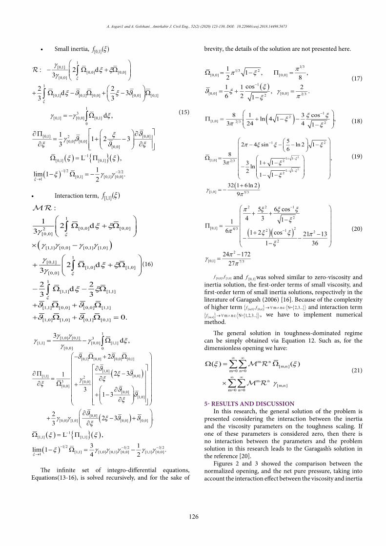
The infinite set of integro-differential equations, Equations(13-16), is solved recursively, and for the sake of
brevity, the details of the solution are not presented here.
( )
1 31 3 2
[0,0] [0,0]
1
[0,0] [0,0] 2 32
1 1 , ,2 8
cos1 1 2, .6 2 1
ππ ξ
ξϑ ξ γ
πξ
−
Ω = − Π =
= + =−
(17)
( )1
2[1,0] 2 3 2
8 1 3 cosln 4 1 ,3 24 4 1
ξ ξξπ ξ
− Π = + − − −
(18)
( )
2
2
1 2
1 1[1,0] 2 3 2
1 12
[1,0] 5 3
52 4 sin ln 2 16
8 ,3 1 13 ln
21 1
32 1 6ln 29
ξ
ξ
π ξ ξ ξ
π ξ
ξ
γπ
−
+ −
− −
− − − −
Ω = + − −
− − +
= −
(19)
( )( )
2 2 1
2
[0,1] 24 3 2 1 2
2
2
[0,1] 7 3
5 6 cos4 3 11
6 1 2 cos 21 131 36
24 17227
π ξ ξ ξ
ξ
π ξ ξ πξ
πγπ
−
−
+ +
− Π =
+ −− − −
−=
(20)
[0,0] [1,0],f f and [0,1]f was solved similar to zero-viscosity and inertia solution, the first-order terms of small viscosity, and first-order term of small inertia solutions, respectively in the literature of Garagash (2006) [16]. Because of the complexity of higher term [m,0] [0,n], m n N= 2,3...f f →∀ ∧ ∈ and interaction term [m,n] m n N= 1,2,3...f →∀ ∧ ∈ , we have to implement numerical method.
The general solution in toughness-dominated regime can be simply obtained via Equation 12. Such as, for the dimensionless opening we have:
m n[m,n]
m=0 n=0
m n[m,n]
m=0 n=0
( ) ( )
ξ ξ
γ
∞ ∞
∞ ∞
Ω = Ω
×
∑∑
∑∑
(21)
5- RESULTS AND DISCUSSIONIn this research, the general solution of the problem is
presented considering the interaction between the inertia and the viscosity parameters on the toughness scaling. If one of these parameters is considered zero, then there is no interaction between the parameters and the problem solution in this research leads to the Garagash’s solution in the reference [20].
Figures 2 and 3 showed the comparison between the normalized opening, and the net pure pressure, taking into account the interaction effect between the viscosity and inertia

127
A. Asgari1 and A. Golshani , Amirkabir J. Civil Eng., 52(2) (2020) 123-130, DOI: 10.22060/ceej.2018.14498.5673
parameters (this study) and without the interaction term [16]. On the other word, considering the interaction effect, it increases the size of the scaled opening and the reduction of the length of the crack.
Considering the effects of interaction term increases thenormalized opening and reduces the length of the crack.
Some of the outcomes of this research are as follows:
5-1- Dimensionless fracture lengthFigure4 shows the contour of the crack half-length in
terms of different values of viscosity and inertia parameters.According to this figure, the crack half-length increases
with the increase of the inertial parameter in the smaller values of the viscosity parameter, and change of crack half-length may become almost negligible for 0.0275 . For a
larger value of the viscosity parameter ( 0.0275>. ), the crack half-length decreases as the inertia parameter becomes greater.
It can also be concluded that the effects of fluid viscosity in the hydraulic fracture injection process are greater than the effects of the inertial parameter. However, ignoring the effects of inertia can even cause about 300% change in the solution under a particular situation.
5-2- The net scaled fluid pressure on the crack surfaceConsidering the FVII, it usually causes a maximum value
to occur in the process of the pressure-space curve (Figure 14). As shown in Fig.ure 5, in a constant inertia, the difference of pressure at the tip and the inlet increases as the viscosity increases.
Increasing the inertia parameter, in the smaller amounts of viscosity, reduces the pressure nearby the injection point and the middle of the crack and increases the pressure around the tip of the crack. On the other hand, the gradual increase of viscosity, the pressure increases at the inlet and decreases in the region of the tip of the crack. These results are due to the existence of the interaction term and . Undoubtedly, the description of the mechanism of interaction between these two parameters seems very complicated and requires more research and laboratory testing with this attitude.
5-3- The Normalized opening of crackFigure 6 shows the trend of opening, Ω = γΩ , for various
values of 0, 0.01,0.02, 0.03, 0.04= and 0, 0.1,0.2,0.3,0.4,0.5,0.6, 0.8=
, with considering FVII with third order ( )3 3O , . As shown, increasing the inertia of the fluid with zero-viscosity the crack may tend to develop a tear-drop shape, whereas, with increasing crack viscosity, the droplet form is released.
6- ConclusionsIn this research, the effect of interaction of viscosity and
inertia parameters on the net pressure in the fracture, the crack opening, and the fracture half-length of crack fluid in brittle rocks for different values of viscosity and inertia parameters for two-dimensional KGD crack in toughness regime using
Figure 2. Comparison of normalized opening, , considering the effect of interaction between viscosity and inertia parameters (this study) and without interaction effect [16].
1.0 0.5 0.0 0.5 1.0
0.5
0.0
0.5
1.00.05 , 0.8
Without Cross Term Garagash, 2006
With Cross Term VII This Study
0.05 , 0.1
0.01 , 0.10.01 , 0.8
Figure 3. Comparison of net fluid pressure, , considering the interaction effect between the viscosity and inertia parameters (this study) and without interaction term [16].
0.05 , 0.8
0.01 , 0.1
0.05 , 0.1
0.01 , 0.8
Without Cross Term Garagash, 2006
With Cross Term VII This Study
1.0 0.5 0.0 0.5 1.0
0.2
0.1
0.0
0.1
0.2
Fig. 2. Comparison of normalized opening, Ω , considering the effect of interaction between viscosity and inertia parameters
(this study) and without interaction effect [16].
Fig. 3. Comparison of net fluid pressure, Π , considering the interaction effect between the viscosity and inertia parameters
(this study) and without interaction term [16].
Figure 4. contour of the crack half-length in terms of different values of viscosity and inertia parameters
Fig. 4. contour of the crack half-length in terms of different values of viscosity and inertia parameters

A. Asgari1 and A. Golshani , Amirkabir J. Civil Eng., 52(2) (2020) 123-130, DOI: 10.22060/ceej.2018.14498.5673
128
modified perturbation method was investigated. The results are briefly noted in the following:
The half-length crack decreases with increasing viscosity and the decreasing trend increases with increasing inertia parameter. In greater amounts of viscosity, an increase in the inertia parameter leads to a decrease in the half-length of the crack. On the other hand, the lowering effect of the viscosity parameter is greater than the inertia enhancing effect. Therefore, it can be concluded that the effects of fluid viscosity in the hydraulic fracture injection process are more than the effects of the inertial parameter with the assumption that the flow is laminar.
Increasing the inertia parameter, in the smaller amounts of viscosity, reduces the pressure nearby the injection point and the middle of the crack and increases the pressure around the tip of the crack. On the other hand, the gradual increase of viscosity, the pressure increases at the inlet and decreases in the region of the tip of the crack. These results are due to the existence of the interaction term and . Increasing the inertia of the fluid with zero-viscosity the crack may tend to develop a tear-drop shape, whereas, with increasing crack viscosity, the droplet form is released.
REFERENCES[1] J.L. Gidley, Recent advances in hydraulic fracturing, (1989).[2] M.J. Economides, K.G. Nolte, U. Ahmed, Reservoir
stimulation, Wiley Chichester, 2000.[3] E. Detournay, D. Garagash, The near-tip region of a fluid-
Figure 5. The trend of net fluid pressure, Π , for various values of and in terms of various values of the viscosity parameter
0.01,0.02,0.03,0.04= , with considering FVII with third-order ( )3 3O ,
Figure 6. The trend of opening, Ω = γΩ , for various values of and
, with considering FVII with third order ( )3 3O ,

129
A. Asgari1 and A. Golshani , Amirkabir J. Civil Eng., 52(2) (2020) 123-130, DOI: 10.22060/ceej.2018.14498.5673
HOW TO CITE THIS ARTICLEA. Asgari, A. Golshani, Analysis of Hydraulic Fracture Propagation in Toughness Dominant with Considering Fluid Viscosity and Inertia Parameters Interaction: Higher Order Terms, Amirkabir J. Civil Eng., 52(2) (2020) 123-130.
DOI: 10.22060/ceej.2018.14498.5673
driven fracture propagating in a permeable elastic solid, Journal of Fluid Mechanics, 494 (2003) 1-32.
[4] D. Spence, P. Sharp, Self-similar solutions for elastohydrodynamic cavity flow, Proceedings of the Royal Society of London. A. Mathematical and Physical Sciences, 400(1819) (1985) 289-313.
[5] R.S. Carbonell, Self-similar solution of a fluid-driven fracture in a zero toughness elastic solid, Proc .Roy. Soc. London. Ser, A submitted for publication, 1996.
[6] J. Desroches, E. Detournay, B. Lenoach, P. Papanastasiou, J. Pearson, M. Thiercelin, A. Cheng, The crack tip region in hydraulic fracturing, in: Proceedings of the Royal Society of London A: Mathematical, Physical and Engineering Sciences, The Royal Society, 1994, pp. 39-48.
[7] J.I. Adachi, Fluid-driven fracture in permeable rock, University of Minnesota, 2001.
[8] A. Asgari, Hydraulic Fracture Propagation in Brittle Rock: Based on Hydro-Mechanical Model, Tarbait Modares University, Tehran, 2016.
[9] D. Garagash, Hydraulic fracture propagation in elastic rock with large toughness, in: 4th North American Rock Mechanics Symposium, American Rock Mechanics Association, 2000.
[10] D.I. Garagash, E. Detournay, Plane-strain propagation of a fluid-driven fracture: small toughness solution, Journal of Applied Mechanics, 72 (2005) 916.
[11] D. Garagash, E. Detournay, Viscosity-dominated regime of a fluid-driven fracture in an elastic medium, in: IUTAM Symposium on Analytical and Computational Fracture
Mechanics of Non-Homogeneous Materials, Springer, 2002, pp. 25-29.
[12] N. Huang, A. Szewczyk, Y. Li, Self-similar solution in problems of hydraulic fracturing, Journal of Applied Mechanics, 57 (1990) 877.
[13] D. Garagash, E. Detournay, The tip region of a fluid-driven fracture in an elastic medium, Journal of Applied Mechanics, 67(1) (2000) 183-192.
[14] R. Nilson, Gas-driven fracture propagation, Journal of Applied Mechanics, 48(4) (1981) 757-762.
[15] G. Batchelor, An Introduction to Fluid Dynamics Cambridge Univ, Press, Bentley House, London, (1967).
[16] D.I. Garagash, Plane-strain propagation of a fluid-driven fracture during injection and shut-in: Asymptotics of large toughness, Engineering Fracture Mechanics, 73(4) (2006) 456-481.
[17] R.A. Shapiro, The dynamics and thermodynamics of compressible fluid flow, New York: Ronald Press, 2(1) (1954).
[18] I.N. Sneddon, M. Lowengrub, P. Mathematician, Crack problems in the classical theory of elasticity, Wiley New York, 1969.
[19] J.R. Rice, Mathematical analysis in the mechanics of fracture, Fracture: an advanced treatise, 2 (1968) 191-311.
[20] D. Garagash, Transient solution for a plane-strain fracture driven by a shear-thinning, power-law fluid, International Journal for Numerical and Analytical Methods in Geomechanics, 30(14) (2006) 1439-1475.

This pa
ge in
tentio
nally
left b
lank