anaerobic water treatment technologies
TRANSCRIPT

Anaerobic Water Treatment Technologies
Shihwu Sung, Ph.D., PEDepartment of Civil, Construction & Environmental EngineeringIowa State University
National Cheng Kung UniversityJuly 4th, 2008

Wastewater Treatment Options
aerobic treatment for soluble chemical oxygen demand (COD) in 50 - 40,000 mg/L range
anaerobic treatment for high CODs (4000 -50,000 traditionally)
alternative processes for CODs < 50 mg/L (e.g., carbon adsorption, ion exchange) and > 50,000 mg/L (e.g., evaporation and incineration)

Anaerobic Waste Treatment : An Overview
Historical development:Mainly used for reducing mass of high solids wastes, e.g. human waste (nightsoil), animal manure, agricultural waste and sludge.
Early applications of anaerobic waste treatment include:
• Mouras automatic scavenger - cited in French journal cosmos in 1881 • Septic tank- developed by Donald Cameron in 1895 (England)

• Imhoff tank: developed by Karl Imhoff in 1905 (Germany)
Imhoff tank is a modified version of septic tank consisted of two - story in which sedimentation was allowed in upper tank and digestion of settled solids in the lower compartment.
Cont..
Uppertank
Lowertank
Imhoff tank

Cumulative Number of AD Plants for Industrial Applications
0
200
400
600
800
1000
1200
1978
1981
1984
1987
1990
1993
1996
1999
No.
of p
lant
s
(Source: (Source: FrankinFrankin, 2001), 2001)

AD – Waste Treatment and Resources Conservation
CH4
, H2
S, H2
, CO2
Anaerobic bioconversion
NH4
+, PO4
3-,S2-
CH4
, H2
S, H2
, CO2
Anaerobic bioconversion
NH4+, PO4
3-,S2-
BiosolidsBiosolids
Organic FertilizerOrganic FertilizerFoodFood
Liquid Wastes(Industrial,Domestic etc.)
Liquid Wastes(Industrial,Domestic etc.)
Slurries(Sewage sludge,Liquid manure)
Slurries(Sewage sludge,Liquid manure)
Solid Wastes(Manure,Organic Refuse)
Solid Wastes(Manure,Organic Refuse)
Agri-
residues(Cropsresidues etc.)
Agri-
residues(Cropsresidues etc.)
Scrubbing Scrubbing
CH4
, H2CH4
, H2
Renewable EnergyRenewable Energy
Treated effluentTreated effluent
IrrigationIrrigation
FoodFood
Post-treatment
Post-treatment
Fish ponds
Fish ponds
FoodFood
So
recoverySo
recovery
Micro-aerobic

Complex OrganicsCarbohydrates
ProteinsLipids
Simple Organics
Volatile Organic AcidsPropionate, Butyrate, etc.
Acetate H2
+ CO2
CH4
+ CO2
1. Hydrolysis
2. Acidogenesis
3. Methanogenesis
(1)
(2)
(3)
Anaerobic Digestion
72% 28%

Advantages of AD
1. Less energy requirement as no aeration is needed0.5-0.75 kWh energy is needed for every 1 kg of COD removal by aerobic process
2. Energy generation in the form of biogas1.16 kWh electricity is produced for every 1 kg of COD removal by anaerobic process
3. Less biomass (sludge) generationAnaerobic process produces only 20% of sludge that of aerobic process


Biodegradableorganic
1 kg
Biodegradableorganic
1 kg
Aerobic process
CO 2 + H 2 O
0.5 kg
CO2 + H2 O
0.5 kg
New biomass
0.5 kg
New biomass
0.5 kg
Anaerobic process
Biogas
> 0.9 kg
Biogas
> 0.9 kg
New biomass
< 0.1 kg
New biomass
< 0.1 kg
Biodegradableorganic
1 kg
Biodegradableorganic
1 kg
Waste + OWaste + O2 2 COCO22+H+H22O + new cellsO + new cells
Waste Waste CHCH44 + new cells+ new cells

4. Less nutrients (N & P) requirementLower biomass synthesis rate also implies less nutrients requirement: 20% of aerobic
5. Application of higher organic loading rate
5-10 times higher organic loading rates than aerobic processes
6. Space saving
Higher loading rate requires smaller reactor volume
7. Ability to transform several hazardous solvents including chloroform, trichloroethylene and trichloroethane
Advantages of AD - continued
Limitations of AD
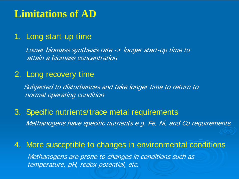
1. Long start-up time
Lower biomass synthesis rate -> longer start-up time to attain a biomass concentration
2. Long recovery timeSubjected to disturbances and take longer time to return to normal operating condition
3. Specific nutrients/trace metal requirementsMethanogens have specific nutrients e.g. Fe, Ni, and Co requirements
4. More susceptible to changes in environmental conditionsMethanogens are prone to changes in conditions such astemperature, pH, redox potential, etc.

5. Treatment of sulfate rich wastewater
The presence of sulfate reduces the methane yield could also inhibit the methanogens due to sulfide toxicity
6. Effluent quality of treated wastewaterMay not able to degrade the organic matter to the level meeting the discharge limits
7. Treatment of high protein & nitrogen containing wastewaterHigh ammonia may cause inhibition
Limitations of AD – continued

Comparison between Anaerobic & Aerobic processes
Anaerobic AerobicOrganic loading rate:High loading rates:10-40 kg COD/m3-day Low loading rates:0.5-1.5 kg COD/m3-day
(for high rate reactors, e.g. AF, & UASB) (for activated sludge process)
High biomass yield:0.35-0.45 kg VSS/kg CODBiomass yield:Low biomass yield:0.05-0.15 kg VSS/kg COD
(biomass yield is not constant but depends on types of substrates metabolized)
(biomass yield is fairly constant irrespectiveof types of substrates metabolized)
Specific substrate utilization rate:
High rate: 0.75-1.5 kg COD/kg VSS-day Low rate: 0.15-0.75 kg COD/kg VSS-day
Start-up time:Long start-up: 1-2 months for mesophilic
: 2-3 months for thermophilicShort start-up: 1-2 weeks

Anaerobic Aerobic
Microbiology:Multi-step process and diverse group ofmicroorganisms degrade organic mattersin a sequential order
Mainly a one-species phenomenon
SRT:Longer SRT is essential to retain the slowgrowing methanogens
SRT of 4-10 days is enough
Environmental factors:
Highly susceptible to changes inenvironmental conditions
Less susceptible to changes in environmental conditions.
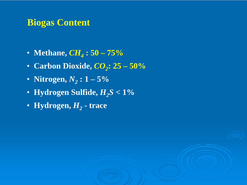
Biogas Content
• Methane, CH4 : 50 – 75%• Carbon Dioxide, CO2 : 25 – 50%• Nitrogen, N2 : 1 – 5%• Hydrogen Sulfide, H2 S < 1%• Hydrogen, H2 - trace

CO2 (g) CO2 (l) + H2 O H2 CO3KH
H2 CO3 H+ + HCO3- H+ + CO3
-2Ka1 Ka2
KH = Henry’s Law constant
pKa1 = 6.33pKa2 = 10.33 at 20oC
Methane Content
• Carbon Dioxide content can be estimated by reactor pHand bicarbonate concentrations
• Methane content is the balance of carbon dioxide

Relationship between pH, bicarbonate
and carbon dioxide at 35oC and 1 atm
pressure
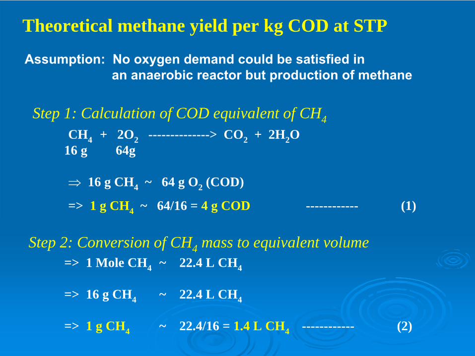
Theoretical methane yield per kg COD at STP
Step 2: Conversion of CH4 mass to equivalent volume=> 1 Mole CH4 ~ 22.4 L CH4
=> 16 g CH4 ~ 22.4 L CH4
=> 1 g CH4 ~ 22.4/16 = 1.4 L CH4 ------------ (2)
Step 1: Calculation of COD equivalent of CH4CH4 + 2O2 --------------> CO2 + 2H2 O
16 g 64g
⇒ 16 g CH4 ~ 64 g O2 (COD)
=> 1 g CH4 ~ 64/16 = 4 g COD ------------ (1)
Assumption: No oxygen demand could be satisfied inan anaerobic reactor but production of methane
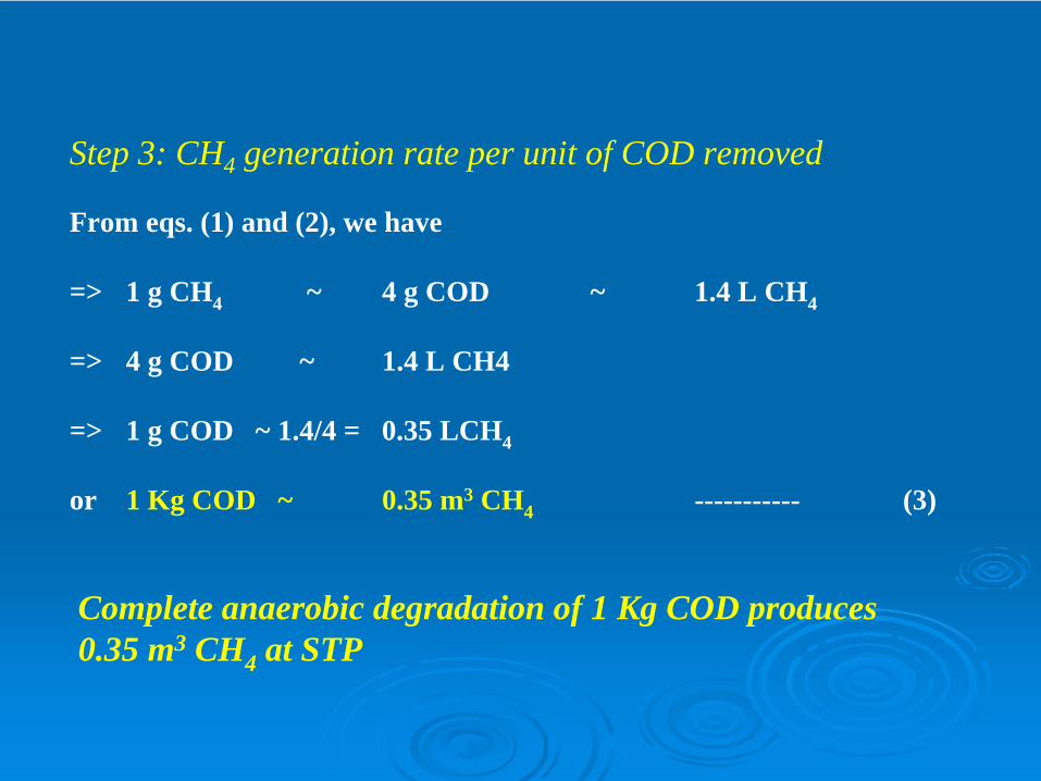
Step 3: CH4 generation rate per unit of COD removed
From eqs. (1) and (2), we have
=> 1 g CH4 ~ 4 g COD ~ 1.4 L CH4
=> 4 g COD ~ 1.4 L CH4
=> 1 g COD ~ 1.4/4 = 0.35 LCH4
or 1 Kg COD ~ 0.35 m3 CH4 ----------- (3)
Complete anaerobic degradation of 1 Kg COD produces0.35 m3 CH4 at STP
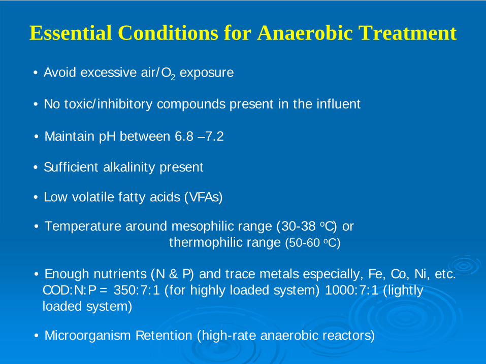
Essential Conditions for Anaerobic Treatment
• Enough nutrients (N & P) and trace metals especially, Fe, Co, Ni, etc. COD:N:P = 350:7:1 (for highly loaded system) 1000:7:1 (lightlyloaded system)
• Avoid excessive air/O2 exposure
• No toxic/inhibitory compounds present in the influent
• Maintain pH between 6.8 –7.2
• Sufficient alkalinity present
• Low volatile fatty acids (VFAs)
• Temperature around mesophilic range (30-38 oC) or thermophilic range (50-60 oC)
• Microorganism Retention (high-rate anaerobic reactors)

Anaerobic Process Configurations
Low rate anaerobic reactors High rate anaerobic reactors
Anaerobic lagoon
Septic tank
Standard rateanaerobic digester
Imhoff tank
Slurry type bioreactor, temperature, mixing, SRT or other environmental conditions are not regulated. Loading of 1-2 kg COD/m3-day..
Anaerobic Sequencing BatchReactor (ASBR)
Anaerobic contact process
Anaerobic filter (AF)
Upflow anaerobic slugdeBlanket (UASB)
Fluidized bed Reactor
Hybrid reactor: UASB/AF
Able to retain very high concentration ofactive biomass in the reactor. Thus extremely high SRT could be maintainedirrespective of HRT. Load 5-20 kg COD/m3-dCOD removal efficiency : 80-90% .

Anaerobic LagoonSuspended growth continuously/batch fed systemTypical depth of lagoons range from 15 to 35 feetLagoons can be covered to collect methane and reduce odors, but can also remain uncovered.Lagoons often used in slaughterhouse industry (FDL Foods, Dubuque, IA)Typical detention times of 1 – 50 daysTemperature dependent
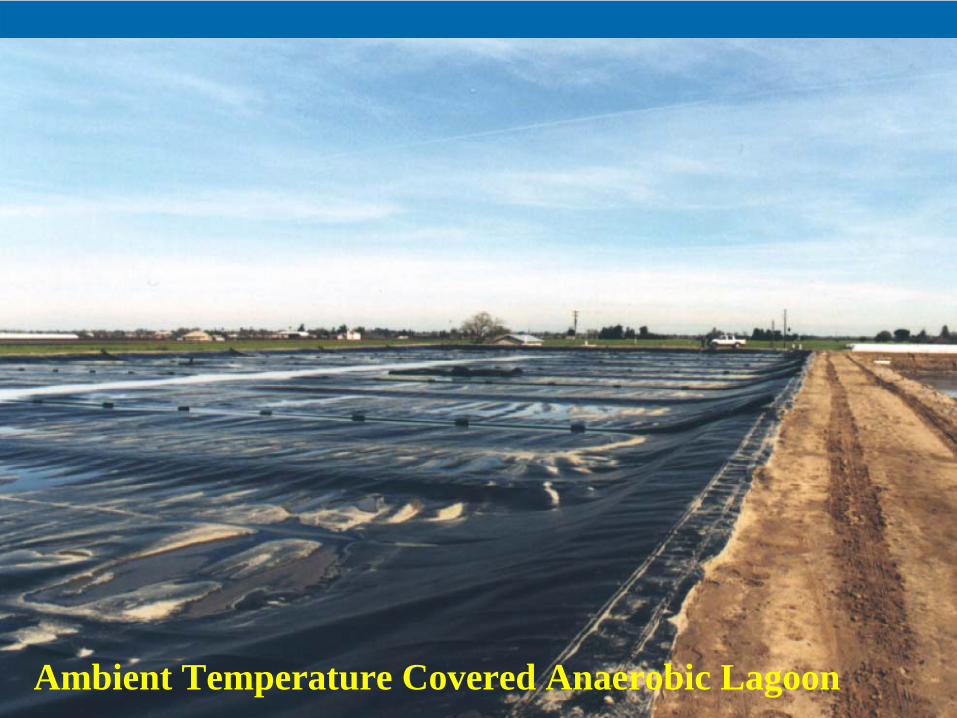
Ambient Temperature Covered Anaerobic Lagoon
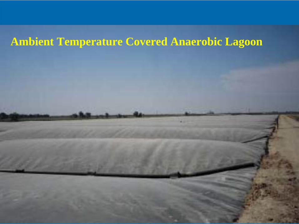
Ambient Temperature Covered Anaerobic Lagoon
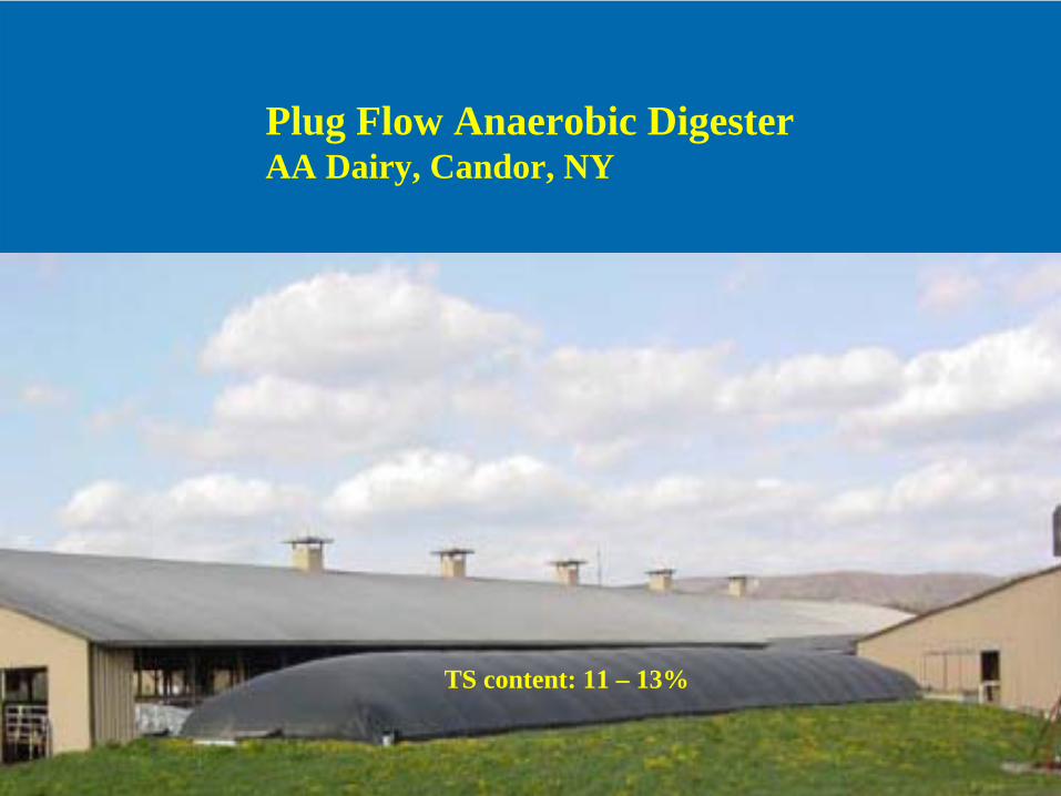
Plug Flow Anaerobic DigesterAA Dairy, Candor, NY
TS content: 11 – 13%

Traditional AD vs. High-Rate AD
• Adequate Mixing
• Temperature Control
• Effective Way to Retain Biomass
- Separate solids retention time (SRT) from hydraulic retention time (HRT). SRT >> HRT
SRT = mass of solids in system (g) / daily solids wasted rate (g/day)

Hydraulic retention time (HRT)
Hydraulic retention time (HRT) is defined:
HRT, days =Volume V (m3)
=Flow rate Q (m3/day)
For a given HRT, the size of reactor can be easily determined since flow rate (Q) is known
Digester volume, V (m3) = Flow rate (Q) x HRT (θH )
V, m3
Influent flow rate(Q), m3/day
Q
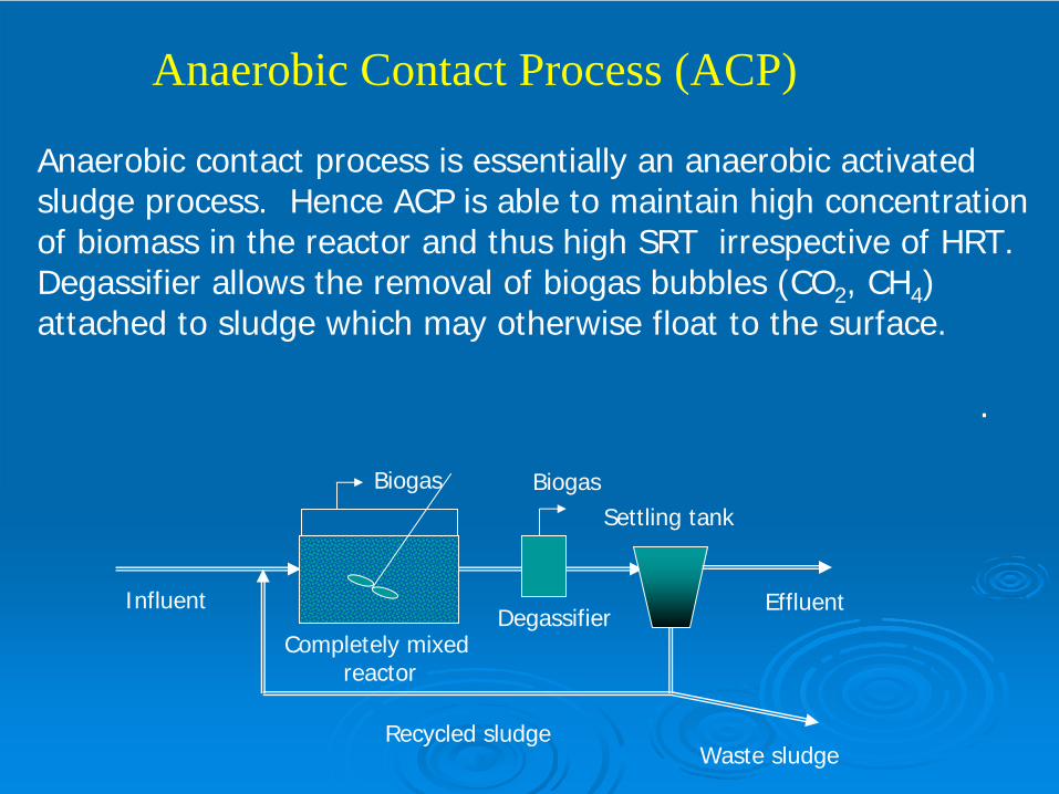
Anaerobic Contact Process (ACP)
Influent Effluent
Waste sludgeRecycled sludge
Completely mixed reactor
Biogas
Degassifier
BiogasSettling tank
Anaerobic contact process is essentially an anaerobic activated sludge process. Hence ACP is able to maintain high concentration of biomass in the reactor and thus high SRT irrespective of HRT.Degassifier allows the removal of biogas bubbles (CO2 , CH4 ) attached to sludge which may otherwise float to the surface.
.

ACP was initially developed for the treatment of dilute wastewater such as meat packing plant which had tendency to form a settleable flocs. ACP is suitable for the treatment of wastewater containing suspended solids.
The biomass concentration in the reactor ranges from 4-6 g/Lwith maximum concentration as high as 25-30 g/L dependingon settleability of sludge. The loading rate ranges from 0.5 –5 kg COD/m3-day. The required SRT could be maintained by controlling the recycle rate similar to activated sludge process.
Cont..
media
effluent
influent
biogas
flow distributionre
circ
ulat
ion
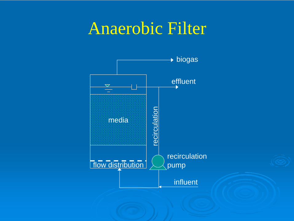
Anaerobic Filter
recirculationpump
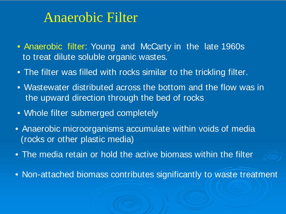
Anaerobic Filter
• Anaerobic filter: Young and McCarty in the late 1960s to treat dilute soluble organic wastes.
• The filter was filled with rocks similar to the trickling filter.
• Wastewater distributed across the bottom and the flow was in the upward direction through the bed of rocks
• Whole filter submerged completely
• Anaerobic microorganisms accumulate within voids of media (rocks or other plastic media)
• The media retain or hold the active biomass within the filter
• Non-attached biomass contributes significantly to waste treatment

Originally, rocks were employed as packing medium inanaerobic filter. But due to very low void volume (40-50%),serious clogging problem was witnessed. Now, many synthetic packing media made up of plastics, ceramic tilesof different configuration have been used in anaerobic filters.The void volume in these media ranges from 85-95 %. Moreover, these media provide high specific surface areatypically 100 m2/m3 or above which enhance biofilm growth.
Cont..

Down flow anaerobic filter is similar to trickling filter in operation. DAF is closer to fixed film reactor as loosely held biomass/sludge within the void spaces is potentially washed out of reactor. There is less clogging problem and wastewater with some SS concentration can be treated using DAF.
Down Flow Anaerobic Filter (DAF)
Cont..
Typically HRT varies from 0.5 – 4 days & the loading ratesvaries from 5 - 15 kg COD/m3-day. Biomass wastage isgenerally not needed.
.
Effluent
Influent
biogas
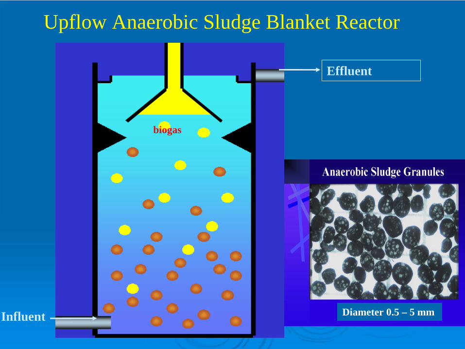
Upflow Anaerobic Sludge Blanket Reactor
Diameter 0.5 – 5 mm

influent
recirculationpump
baffles
granular sludge
gasbubbles
threephase separator
biogas
flocculentsludge
distribution baffle
effluentweir
effluent
UASB
granulegas bubble
floc particle

originalgranule diameter
gravitational force
buoyancyforce
upflow velocity
gas bubbles
Upf
low
in U
AS
B re
acto
r
Upf
low
in U
AS
B re
acto
r

Upflow Anaerobic Sludge Blanket (UASB)
UASB was developed in 1970s by Lettinga in the Netherlands. UASB is essentially a suspended growth system in which proper hydraulic and organic loading rate is maintained in order to facilitate the dense biomass aggregation known as granulation. The size of granules is about 1-5 mm diameter. Since granules are bigger in size and heavier, they will settle down and retain within the reactor. The concentration of biomass in the reactor may become as high as 50 g/L. Thus a very high SRT can be achieved even at very low HRT of 4 hours.
The granules consist of hydrolytic bacteria, acidogen/acetogensand methanogens. Complex organic degrading granules show layered structure with a surface layer of hydrolytic/fermentativeAcidogens. A mid-layer comprising of syntrophic colonies and an interior with acetogenic methanogens.

Loading rate:15-30 kg COD/m3-day
Important components of UASB:1. Influent flow distributor2. Sludge blanket3. Solid-liquid-gas separator4. Effluent collector
Type of waste treatable by UASB:Alcohol, bakers yeast, bakery, brewery, candy, canneries,chocolate, citric acid, coffee, dairy & cheese, distillery, Domestic sewage, fermentation, fruit juice, fructose, landfill leachate,paper & pulp, pharmaceutical, potato processing, rubber,sewagesludge liquor, slaughter house, soft drinks, starch (barley, corn,wheat), sugar processing, vegetable & fruit, yeast, etc.
Cont..

Important considerations in UASB operation
• Provide optimum pH, and enough alkalinity.
• Addition of Ca2+ at 200 mg/L promotes granulation. Ca2+ conc.higher than 600 mg/L may form CaCO3 crystals which mayallow methanogens to adhere to and then become washed outof the system.
• Initial seeding of some well digested anaerobic sludge couldbe used. The seed occupies 30-50% of total reactor volume.Minimum seeding is 10% of the reactor volume.
• Supplement nutrients and trace metals if needed. Provide N & P at a rate of COD: N:P of 400:7:1 (conservative estimate).

Expanded Granular Sludge Bed (EGSB) Reactor
USAB
EGSB (Triple Baffle Internal Settler)
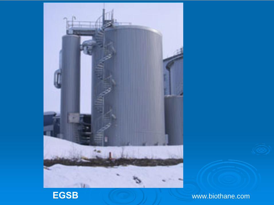
www.biothane.comEGSB

SETTLE DECANT FEED REACT
SETTLED BIOMASS
SUPERNATANT
DECANT PORTS
BIOGAS RECYCLE
EFFLUENT FEED
BIOGAS
Anaerobic Sequential Batch Reactor (ASBR)Anaerobic Sequential Batch Reactor (ASBR)

Anaerobic Sequencing Batch Reactor (ASBR)
Developed at Iowa State University by Dague and SungBatch fed suspended growth system.ASBR relies on internal clarification for solids retention by allowing biomass to settle.Four distinct phases – Feed – React – Settle - DecantFour phases compose one cycle.Cycle lengths vary from 4 to 24 hours.Good system for wastes with high solids.Studies show that intermittent mixing is as effective as continuous mixingLow F/M at end of react cycle allows low gas production during settle phase.By lowering settle time selection of better settling granules can occur.Granulation is key to system (see UASB).

ASBR
Demonstration atCrawford farm

ASBR Digester- Liquid Swine Waste

Temperature-Phased Anaerobic Digestion (TPAD)
LABORATORY SETUP
Feed Tank Thermophilic at 55oC
Mesophilic at 35oC
H2 S scrubber H2 S scrubber
Gasmeter Gasmeter
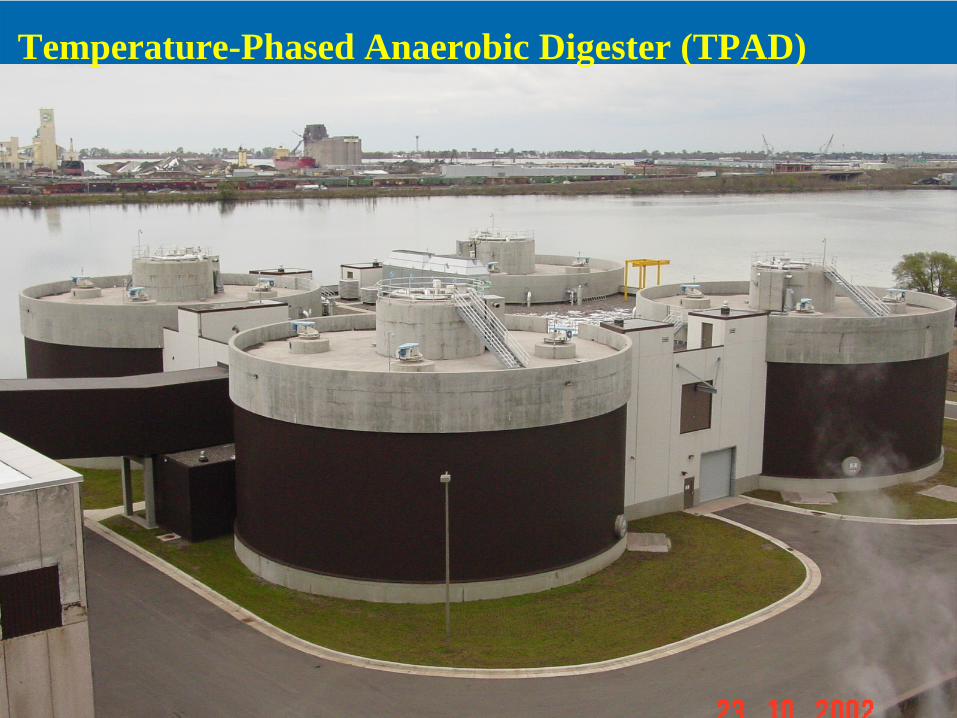
Temperature-Phased Anaerobic Digester (TPAD)
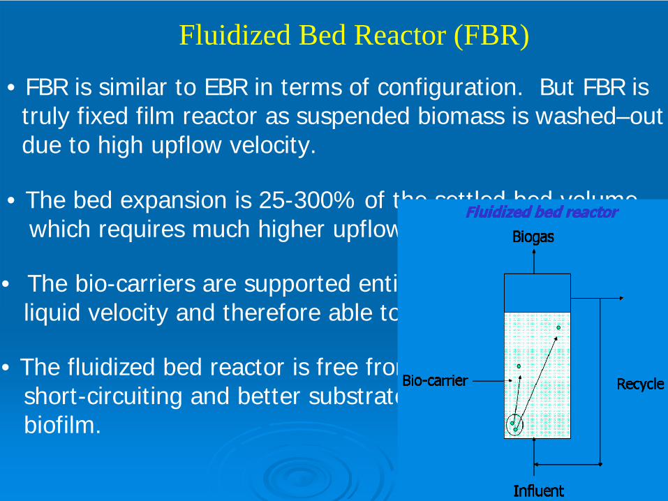
Fluidized Bed Reactor (FBR)
• FBR is similar to EBR in terms of configuration. But FBR istruly fixed film reactor as suspended biomass is washed–outdue to high upflow velocity.
• The bed expansion is 25-300% of the settled bed volumewhich requires much higher upflow velocity (10-25 m/hr).
• The bio-carriers are supported entirely by the upflowliquid velocity and therefore able to move freely in the bed.
• The fluidized bed reactor is free from clogging problem short-circuiting and better substrate diffusion within the biofilm.
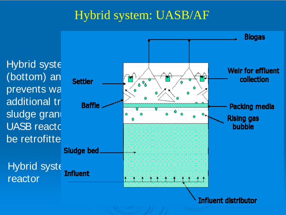
Hybrid system: UASB/AF
Hybrid system incorporates both granular sludge blanket(bottom) and anaerobic filter (top). Such approach prevents wash-out of biomass from the reactor. Furtheradditional treatment at the top bed due to the retention ofsludge granules that escaped from the bottom sludge bed.UASB reactor facing a chronic sludge wash-out problem canbe retrofitted using this approach.
Hybrid system may be any combination or two types of reactor

Biogas
Sludge
Anaerobic baffled reactorIn anaerobic baffled reactor, the wastewater passes overand under the baffles. The biomass accumulates in Between the baffles which may in fact form granules withtime. The baffles present the horizontal movement ofof biomass in the reactor. Hence high concentration ofbiomass could be maintained within the reactor.

Low energy consumption (no aeration needed)Low sludge production(1/5th of aerobic)Able to maintain long SRT - minimize biomass wash-out
Superior effluent quality for water reuse
Useful energy byproduct – methane
Operation at ambient temperature
Minimum knowledge of AMBR for low strength wastewater
Membrane
Anaerobic bioreactor
Anaerobic Membrane Bioreactor (AMBR)
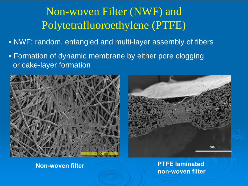
Non-woven Filter (NWF) and Polytetrafluoroethylene (PTFE)
Non-woven filter PTFE laminated non-woven filter
500μm
• NWF: random, entangled and multi-layer assembly of fibers
• Formation of dynamic membrane by either pore clogging or cake-layer formation

25.0
pH ORPLevel Sensor
25.0
pH ORPLevel Sensor
Outlet Pressure
Inlet Pressure
Pressure Valve
Peristaltic Pump
P
Outlet Pressure
Inlet Pressure
Pressure Valve
Peristaltic Pump
P
25.0
pH ORPLevel Sensor
25.0
pH ORPLevel Sensor
Outlet Pressure
Inlet Pressure
Pressure Valve
Peristaltic Pump
P
Outlet Pressure
Inlet Pressure
Pressure Valve
Peristaltic Pump
P
AMBR schematic

Acknowledgement:These studies were supported by grants from• Midwest Grain Processors (MGP); Lakota, IA• Western Lake Superior Sanitary District, Duluth, MN• Iowa Energy Center, Nevada, Iowa• Black & Veatch Corporations, Kansas, KS• U.S. Department of Energy • U.S. Department of Agriculture through Iowa
Biotechnology Byproducts Consortium

Question?