an2764, improving the transient immunity performance of
TRANSCRIPT

Freescale SemiconductorApplication Note
AN2764Rev. 0, 06/2005
Improving the Transient Immunity Performance of Microcontroller-Based Applicationsby: Ross Carlton, Greg Racino, John Suchyta
Freescale Semiconductor, Inc.
Introduction
Increased competition among appliance manufacturers, as well as market regulatory pressures, are challenging original equipment manufacturers (OEMs) to reduce the cost of their products while ensuring compatible operation in increasingly severe electro-magnetic environments. As a result of this focus on cost control, implementing the necessary transient immunity protections to prevent appliance malfunction due to transients on power and signal lines is becoming ever more challenging for the appliance designer. Because traditional power supply designs and electro-magnetic interference (EMI) controls are sacrificed for lower-cost solutions, the appliance designer must develop new techniques to meet applicable regulatory electro-magnetic compatibility (EMC) requirements.
This application note discusses the effects of transient electrical disturbances on embedded microcontrollers (MCUs) and suggests practical hardware and software design techniques that can provide cost-effective protection for electrical fast transients (EFT), electrostatic discharge (ESD), and other power line or signal line transients of short duration. Although this discussion is targeted at appliance manufacturers, these principles also apply to applications in consumer, industrial, and automotive electronics.
© Freescale Semiconductor, Inc., 2005. All rights reserved.

The Challenge
The Challenge
As real-world electrical disturbances are understood and modeled, new standards are developed to characterize, monitor, and qualify the effects of these disturbances in applications. These standards provide guidance for the appliance system designer and challenges for the integrated circuit (IC) and component designers.
Environment
The transient immunity environment for commercial electrical and electronic products includes both electrostatic discharge (ESD) and electrical fast transients (EFT). These transients are defined in IEC 61000-4-21 (or ANSI C63.16) and IEC 61000-4-42, respectively. These standards include test methods that are performed by the OEM designer to meet product specifications and regulatory requirements.
The ESD waveform is intended to simulate the discharge from a human operator. The electrostatic discharge is injected at any location that the operator is likely to touch. This includes all user accessible controls and external connectors. The test levels for ESD vary widely depending on application. Values for air and contact discharge can be as low as 2 kV for commercial applications or as high as 20 kV for some automotive applications. The ESD waveform specified in IEC 61000-4-2 has a rise time of 0.7 ns to 1.0 ns, resulting in a noise bandwidth (1/πtr) of approximately 450 MHz.
The EFT waveform is intended to simulate the transients created by the switching of relays or the interruption of inductive loads on the power mains. Though primarily intended for injection on the product’s AC power cord, the EFT waveform can also be injected onto signal and control lines to simulate the coupling of the EFT onto these lines. Although test levels for the EFT transient are specified with amplitudes as high as to 4 kV, higher levels of immunity performance are sometimes required for particularly severe environments. The EFT waveform specified in IEC 61000-4-4 has a rise time of 3.5 ns to 6.5 ns resulting, in a noise bandwidth (1/πtr) of approximately 90 MHz.
Issues In Embedded Applications
Low-cost, MCU-based embedded applications are particularly susceptible to performance degradation during ESD and EFT events. This sensitivity to fast rise time transients is to be expected, even for MCUs running at relatively low clock frequencies. This sensitivity is due to the process technologies used. Today’s semiconductor process technologies for low-cost, 8-bit and 16-bit MCUs implement transistor gate lengths in the 0.65 µm to 0.25 µm range. These gate lengths are capable of generating and responding to signals with rise times in the sub-nanosecond range (or an equivalent bandwidth of greater than 300 MHz). As a result, an MCU is capable of responding to ESD or EFT signals injected onto its pins.
Improving the Transient Immunity Performance of Microcontroller-Based Applications, Rev. 0
2 Freescale Semiconductor

The Challenge
In addition to the process technology, MCU performance in the presence of an ESD or EFT event is affected by the design of the IC and its package, the design of the printed circuit board (PCB), the software running on the MCU, the design of the system, and the characteristics of the ESD or EFT waveform when it reaches the MCU. The relative impact of each performance driver (where to focus effort for maximum effect) is shown in the pie chart in Figure 1.
Figure 1. Performance Driver Impact on Application Transient Immunity
IC design considerations, other than those directly related to the process technology, have an effect on MCU performance when subjected to transients. These design considerations include the composition of ESD suppression devices on I/O pins, the design and layout of I/O pin structures, and any dedicated EMC circuitry. ESD devices, which are normally designed to prevent damage during part handling and PCB assembly operations, can range from simple diodes and FET snap back mode protection to complex active filters. The design of these ESD protection components must ensure compatibility with the need for powered and operational transient protection. The design and layout of I/O pin structures must be done carefully to prevent device damage due to electrical over-stress (EOS) and unwanted current injection. EMC controls and other techniques, such as physical separation or circuit isolation, will also impact transient immunity performance — potentially at a significant cost due to die size impact.
The choice of MCU package has an effect on transient immunity performance. The primary package characteristics that impact transient immunity performance are package type and package dimensions. The package type will determine the baseline impedance of the package pins due to the resistance and coupling (capacitive and inductive) to adjacent pins and/or bond wires. If the package employs a substrate to connect the die bond pads to the package pins, its impedance characteristics will also impact performance. Note that while there are exceptions, similar package types tend to have similar performance characteristics because they have similar capacitances and impedances. Package dimensions influence PCB layout and composition. For example, surface-mount packages generally have smaller footprints than equivalent through-hole packages that can reduce overall PCB dimensions or provide more space to implement board-level suppression techniques.
MCU PACKAGE
PROCESS TECHNOLOGY
MCU DESIGN
PCB DESIGN
SYSTEM DESIGN
Improving the Transient Immunity Performance of Microcontroller-Based Applications, Rev. 0
Freescale Semiconductor 3

The Challenge
Areas of MCU Vulnerability
Considering that most MCUs are specified and designed to generate and respond to signals with rise times comparable to ESD and EFT events, vulnerability to these events should be expected. Areas of MCUs that are typically vulnerable to ESD and EFT signals include:
• Power and ground pins• Edge-sensitive digital inputs• High-frequency digital inputs • Analog inputs• Clock (oscillator) pins• Substrate• Multiplexed pin functions• ESD protection circuitry
Some MCUs have multiple power and ground pins to isolate high speed digital functions from low speed or noise-sensitive analog functions. These supply pins should be filtered appropriately to prevent disturbances in one functional area from affecting another. Low-cost MCUs may have only a single set of power and ground pins, which makes isolation difficult, and consequentially makes filtering more important. A transient that gets propagated to a supply line can potentially disrupt any circuit connected to the power distribution system.
Edge-sensitive inputs are particularly vulnerable to transients. These inputs are usually timer or external interrupt inputs. Even with external low-pass filtering connected to the input, a sufficiently large transient can inject enough energy to disrupt MCU operation. Transients that don’t disrupt the MCU can still be propagated as glitches (see Figure 2).
Figure 2. Transient Generation of Logic Glitches
High speed digital inputs, such as clock and data inputs, are less likely to have low-pass filtering and consequently can register transients as valid data pulses. External isolation techniques are necessary to eliminate this vulnerability.
Analog inputs are generally lower impedance than digital inputs and can experience physical damage if not protected during ESD and EFT transients. However, on most MCUs, the analog inputs are multiplexed with general-purpose I/O pins and have a small sampling window in which the lower input impedance is active. A transient appearing at an analog input pin during an analog-to-digital conversion will result in distorted data due to the signal disruption. Effective software filtering techniques help mitigate this vulnerability.
GLITCH
Improving the Transient Immunity Performance of Microcontroller-Based Applications, Rev. 0
4 Freescale Semiconductor

The Challenge
Most MCUs have a built-in oscillator amplifier so that an external crystal or resonator is all that is needed to ensure a stable high-frequency system clock. The oscillator pins can pass noise pulses as valid clock edges and are considered to be the most vulnerable inputs to the system. Appropriate PCB layout is the preferred method to eliminate this risk.
As shown in Figure 3, transients can travel from the point of entry and affect circuits via several paths. Signal path #1 results from the I/O pin input circuitry attempting to process the transient as if it were data. A false signal can be sent to core circuitry, such as the Serial Peripheral Interface (SPI) which can cause data corruption. As shown by signal path #2, system input signals that exceed the power rails of the MCU will inject current into the I/O pin structure as soon as the signal level exceeds the ESD protection diode’s forward bias voltage. The I/O pin structure and on-chip ESD protection network can dissipate small amounts of injected energy. However, if the injected current is greater than the local circuit can handle, this excessive current can find alternative paths through the supply rails or substrate and disrupt other circuitry. The final signal path, shown by #3, is due to current being injected into the device substrate. Substrate injection currents can flow to remote locations on the die and disrupt sensitive analog circuitry. Current injection is generally minimized by using series resistors.
Figure 3. Transient Current Injection Paths Inside the MCU
General-purpose MCUs have I/O ports that can have more that one function multiplexed on a pin. An electrical disturbance that causes enough energy to disrupt digital logic can also affect the local circuitry that selects the pin function. The resulting fault could change the pin state, the pin directionality, or the pin function.
Vulnerability is particularly troublesome for general-purpose MCUs that are designed to meet the needs of many applications. For these MCUs, it is impractical or impossible to protect all vulnerable areas without adversely affecting functional performance in at least some applications.
Application-specific MCUs can be protected with greater success, but some vulnerability will continue to exist if the operational frequency or bandwidth of the MCU overlaps the bandwidth of the ESD and EFT signals.
SPI
ATD
CPU
MEMORY
SILICON p– SUBSTRATE
1
2
VSS
VDD
3
Improving the Transient Immunity Performance of Microcontroller-Based Applications, Rev. 0
Freescale Semiconductor 5

The Challenge
MCU Failure Modes
Failure modes for integrated circuits (ICs) are typically classified into one of five categories as specified in IEC 62132-1 and shown in Table 1. The classification is determined by the performance of the IC in the presence of the ESD or EFT signal. This performance is dependent on the type of IC and its functional and parametric operation as documented in its data sheet.
Freescale’s interpretation of the IEC’s classification of IC EMC degradation specific to MCUs is shown in Table 2. The resulting table recognizes that there are two distinct levels of recovery for IEC level C: external reset and power-on reset (or cycling power). Each of these functions can be performed with external circuitry or by operator intervention.
For MCUs, performance degradation can take many forms. Common forms of temporary degradation include but are not limited to internal reset, latch-up, memory corruption, and code runaway. MCUs with internal reset circuits can generally resume operation without operator involvement if the fault is an unexpected reset or code runaway that is caught by a watchdog timer. External reset circuits may be required when internal reset circuits are not suitable. Recovery from latch-up and volatile memory corruption (RAM) requires cycling the power to the system. Nonvolatile memory corruption (FLASH, EEPROM) requires a more extensive process of re-programming the system, which can be viewed as a
Table 1. IEC Classification of IC Performance Degradation
Class Description
A All functions of the IC perform as designed during and after exposure to a disturbance.
BAll functions of the IC perform as designed during exposure; however, one or more of them may go beyond the specified tolerance. All functions return automatically to within normal limits after the disturbance is removed. Memory functions shall remain Class A.
CA function of the IC does not function as designed during exposure but returns automatically to normal operation after the disturbance is removed.
DA function of the IC does not function as designed during exposure and does not return to normal operation until the disturbance is removed and the IC is reset by simple operator action.
EOne or more functions of the IC do not perform as designed during and after exposure and cannot be returned to normal operation.
Table 2. Freescale Classification of MCU Performance Degradation
Class Description
A Normal performance within the specification limits during application of the transient
BTemporary degradation or loss of function or performance which is self-recoverable after the transient is removed. Device returns to normal performance.
CTemporary degradation or loss of function or performance which requires an external reset after the transient is removed. Device returns to normal performance.
DTemporary degradation or loss of function or performance which requires that power be cycled after the transient is removed. Device returns to normal performance.
EPermanent degradation or loss of function which is not recoverable due to damage or loss of data
Improving the Transient Immunity Performance of Microcontroller-Based Applications, Rev. 0
6 Freescale Semiconductor

Hardware Techniques
temporary MCU degradation if the system can be re-worked, or as a permanent degradation if it cannot be re-worked.
Permanent degradation is typically due to silicon damage that can cause increased leakage current on input/output (I/O) pins or power pins. The damage can affect analog measurements, input impedances, and output drive strength. With increased leakage current, the electronic system may still operate within specification for a while, but it may ultimately fail due to damage from the transient stress. Other permanent degradation can be caused by melted or fused power traces and bond wires resulting in opens and/or shorts.
Impact of MCU Design Trends
The MCU design trend that particularly impacts transient immunity performance is the drive to continually reduce the minimum gate length of individual field effect transistors (FETs), making them smaller and faster. This trend is the result of market pressure on semiconductor manufacturers to reduce the cost of their products by making die sizes smaller. The result is that maintaining the immunity performance of MCUs is becoming increasingly difficult. When coupled with continuing cost reductions by OEMs at the application or system level, the immunity problem becomes more severe.
MCU designers are challenged to develop better methods to dissipate the energy injected during a transient event. Although designers would appreciate more area in which to include transient suppression circuits, this is generally not allowed in order to keep the die size and cost to a minimum. Some of the remaining options available to the designer include modifying semiconductor attributes (doping and materials) and changing the vertical structure of the I/O pin.
Hardware Techniques
The hardware design techniques used for an application will establish the baseline immunity performance. The purpose of hardware techniques is to protect the MCU from performance degradation or long-term MCU reliability problems.
Hardware techniques should be maximized to ensure desired EMC performance before attempting any software techniques. This is important because software techniques do not reduce the level of transients to which the MCU is exposed — they only reduce the impact of these signals on system operation. Even though the application performance may not be degraded, exposure to transients can adversely affect long-term reliability.
In order to produce an application that meets both the regulatory EMC requirements and minimizes cost, the design process must be both methodical and iterative. Rigorous system and PCB design methodologies are required to ensure quality and consistency in the design process. Without such methodologies, achieving EMC compliance will be accidental and unrepeatable. The design process must also be iterative to ensure the best possible system design and PCB layout. A design that minimizes cost cannot be completed properly in one pass — regardless of the quality of personnel or tools. An EMC-compliant, low-cost application is the result of close and consistent collaboration between the EMC engineer and all other engineering disciplines (i.e., electrical engineers, mechanical engineers, PCB layout engineers, etc.).
Improving the Transient Immunity Performance of Microcontroller-Based Applications, Rev. 0
Freescale Semiconductor 7

Hardware Techniques
Transient Suppression and Control Components
Components used to suppress or control transients, as well as their implementation details and RF characteristics, are described in technical documentation from the component manufacturers as well as in many books, papers, and articles. Therefore, this application note will not go into detail on component selection and specific usage. The following paragraphs provide a basic description of how the most typically used components are employed in low-cost designs for achieving the desired level of transient immunity.
Components used to suppress or control transients can be grouped into two main categories:
• Components that shunt transient currents (voltage limiters)
• Components that block transient currents (current limiters)
Note that depending on the rise time (frequency bandwidth) of the transient, a component may function as either a shunt or a block. For instance, at a slow rise time (low frequency bandwidth) an inductor will have little impedance (a shunt). At faster rise times (higher frequency bandwidth), an inductor will have greater impedance (a block). As a result, transient suppression components must be carefully selected for the optimal operating conditions. The actual performance of the component in the application will depend on the frequency-based characteristics of the component and the board layout.
Resistors
Series resistance between two nodes can provide inexpensive and effective transient protection blocking or limiting transients with frequency-independent resistance. Resistance can be used to create low-pass filters and to decouple power domains. Series resistance is primarily suited to protecting digital or analog signals that carry low currents and can accept a modest voltage drop (across the series resistance). Typically, wire-wound or carbon-composition resistors are used due to their ability to survive large transient currents. Important characteristics to consider when selecting resistors are the steady-state maximum power rating, maximum working voltage, and dielectric withstand voltage. The parasitic shunt capacitance and series inductance of a resistor do not require special consideration in transient protection applications.
Capacitors
Capacitors are used in a variety of transient protection roles: bypassing or charge storage (as a limiter of voltage variations) and power decoupling (as a shunt element in a low-pass filter or a series element in a high-pass filter). In either role, the capacitor can be used to effectively shunt fast transients of limited energy, such as ESD or EFT. Capacitors are not practical for shunting larger transient currents due to lightning, surge, or switching large inductive loads. Important characteristics to consider when selecting capacitors are the maximum DC voltage rating, parasitic inductance, parasitic resistance, and over-voltage failure mechanism. When used in conditions where the maximum voltage rating may be exceeded, capacitors should be of the self-healing type, such as the metallized polyester film capacitor.
Ferrite Beads and Inductors
Ferrite beads and inductors are used to decouple power domains by creating low-pass filters. In these applications, a series ferrite bead or inductor is used to block or limit transients with frequency-dependent impedance. Series inductance is primarily suited to protecting power lines and digital or analog signals
Improving the Transient Immunity Performance of Microcontroller-Based Applications, Rev. 0
8 Freescale Semiconductor

Hardware Techniques
that carry high currents or cannot accept the voltage drop imposed by a series resistance. Important characteristics to consider when selecting ferrite beads or inductors are the maximum DC current rating, parasitic resistance, permeability of the ferrite material, DC resistance, and parasitic inter-winding capacitance in the case of wound inductors.
Common-Mode Chokes
Common-mode chokes present a large inductance in series with common-mode sources and small or negligible inductance in series with differential-mode sources. These inductances suppress common-mode signals while having a negligible effect on power frequency differential-mode signals. As a result, the common-mode choke is one of the most effective transient protection components. When used with capacitors to form a low-pass filter, common-mode chokes can be even more effective. Important characteristics to consider when selecting a common-mode choke are the maximum differential-mode DC current rating, common-mode inductance, differential-mode inductance, and DC resistance.
Filters
Filters are used to achieve greater performance than single capacitive or inductive components. Filters use multiple capacitive and inductive components that are specifically selected to achieve the desired performance.
Transient Voltage Suppressors
The transient voltage suppressor (TVS) is used to control and limit the voltage developed across any two or more terminals. The TVS accomplishes this task by clamping the voltage level and diverting transient currents from sensitive circuitry when a trigger voltage is reached. TVS devices tend to have response times in inverse proportion to their current-handling capability. As a result, two devices (one with slow response and high current capability and one with fast response but low current capability) are often required to achieve the desired protection level.
TVS devices can be used to suppress transients on the AC mains, DC mains, and other power supply systems. They can also be used to clamp transient voltages generated by the switching of inductive loads within an application.
Varistors
The varistor (or voltage-variable resistor) is a non-linear, symmetrical, bipolar device that dissipates energy into a solid, bulk material such as a metal oxide in the case of the common metal oxide varistor (MOV). As a result, the varistor will effectively clamp both positive and negative high current transients. The one issue with varistors is that the actual trigger voltage can vary widely from the specified value. Transient protection designs using varistors must accommodate this characteristic. Currently, MOVs are the best of the available non-linear devices for the protection of electronics from transient voltages propagating on the AC mains.
Improving the Transient Immunity Performance of Microcontroller-Based Applications, Rev. 0
Freescale Semiconductor 9

Hardware Techniques
Avalanche and Zener Diodes
The avalanche and Zener diodes are silicon diodes intended for operation in the reverse breakdown mode. The primary difference between these two diodes is the mechanism of reverse breakdown: avalanche or Zener. Typically, the Zener diodes have a reverse breakdown voltage of less than 5 V while diodes with reverse breakdown voltages of greater than 8 V use the avalanche mechanism.
System Power and Signal Entry
The first and best opportunity to eliminate transient immunity problems is at the point of power or signal entry into the application. If the immunity signal can be sufficiently suppressed at this point, the remaining hardware and software techniques may not be necessary. The impact of this is twofold: the risk on noncompliance is reduced or eliminated; and the cost and effort in other areas of the design are reduced.
Examples of point of entry power filters and signal line filters are shown in Figure 4 and Figure 5, respectively. Power filters are readily available from numerous vendors in both standard and custom packages. Filter performance can also be selected from standard offerings or customized for the particular application.
Figure 4. Point of Entry Power Filter Examples
Figure 5. Point of Entry Signal Line Filter Examples
STANDARD FILTERS CUSTOM FILTERS
Improving the Transient Immunity Performance of Microcontroller-Based Applications, Rev. 0
10 Freescale Semiconductor

Hardware Techniques
If power and signal connections to the application are not optimized for transient suppression at the point of entry, the compliance problem increases in complexity because control of the immunity signals has been lost. The result is that all of the remaining hardware and software techniques may be needed to ensure good EMC performance.
These two conditions are illustrated in Figure 6. Transient suppression devices suitable for point of entry applications are readily available from numerous suppliers or, if needed or desired, custom solutions can be designed.
Figure 6. Point of Entry Filter Placement
System Connector Location
If power and signals are filtered at their point of entry into the application, the location of connectors is not critical. However, if the power and signals are not filtered, connector location becomes very important. In this case, connectors should be located so that the cable’s length between the application chassis and the connected load is as short as possible. A short connection will reduce the amount of energy radiated into the chassis but will have no effect on the conducted immunity signal. In addition, separate power connectors from signal connectors as much as possible.
System Cable Routing
Where cable lines are unfiltered, never, under any circumstances, route power lines and signal lines in the same cable bundle. Doing so will only ensure that the noise on the power/signal lines will be coupled to the other signal/power lines in the bundle. Failing to follow this rule will serve to maximize the complexity of the problem by ensuring many more noisy signals in the system.
Where cable lines are filtered, power and signal lines may be routed together in the same cable bundle only if there is no possibility of creating a self-compatibility problem. For instance, a self-compatibility problem may exist if the application contains subsystems or components that generate transient noise (e.g., relays, motors, and compressors) as a result of normal operation. If the possibility of a self-compatibility problem exists, default to the rule for unfiltered lines.
CONDUCTEDFILTER
PCB2
PCB1
CONDUCTED
RADIATED PCB2
PCB1
Filtered — Conducted immunity signal suppressed. Clean power supplied to PCB1 and no internal radiation.
No Filter — Conducted immunity signal propagates to PCB1 and radiates to couple to PCB2 and interior cables.
Improving the Transient Immunity Performance of Microcontroller-Based Applications, Rev. 0
Freescale Semiconductor 11

Hardware Techniques
System Component Placement
The placement of subsystems, components or cables is important — particularly for self-compatibility. Noisy subsystems, components or cables should be physically isolated from sensitive electronics, such as the MCU, to minimize radiated noise coupling. Physical isolation can take the form of separation (distance) or shielding.
Also, separate AC-to-DC power supply circuits from analog and digital logic circuits. If possible, use a separate, dedicated PCB for AC-to-DC power supply circuits.
System and PCB Power Supply
The second opportunity to eliminate transient immunity problems is at the application’s power supply. The transient protection in the power supply can be standalone or be designed to work in conjunction with protection at the power entry point. In either case, protection is required to prevent damage to the power supply and logic components as well as to prevent any performance degradation of the application.
Power supply designs typically fall into one of two categories: linear or switching. A basic representation of each type of power supply is shown in Figure 7. Each design style has its own considerations for ensuring transient immunity in the application.
Figure 7. Power Supply Types
Advances in power supply design technology have allowed the development of new low-cost versions of traditional power supply designs. Although low-cost designs are very attractive, cost reductions are typically achieved at the expense of EMC. Therefore, the successful implementation of a low-cost design will require greater planning and expertise to meet the required immunity performance levels.
Traditional Linear Power Supply
The linear AC-to-DC power supply can be approximated as a series resistance between the input and the output. Feedback control can optionally be used to provide a specified output voltage by varying the value of the series resistance. Traditional linear power supplies have many positive performance characteristics, such as excellent EMI performance, but are limited in applications by efficiency, heat dissipation, and size. A block diagram of a generic linear power supply is shown in Figure 8.
LINEAR POWER SUPPLY SWITCHING POWER SUPPLY
VOUT
+
–
RLCONTROL VOUT
+
–
RL
CONTROL
CO
Improving the Transient Immunity Performance of Microcontroller-Based Applications, Rev. 0
12 Freescale Semiconductor

Hardware Techniques
Figure 8. Generic Linear Power Supply
Neither the DC output nor the ground should be directly connected to the AC mains (line or neutral) unless required for functionality. In addition, there are four areas of a traditional linear power supply that require consideration and possibly protection. These areas are described as follows:
1. The transformer (or the rectifier diodes, if a transformer is not used), needs protection from excessive primary common mode and differential mode voltages on the AC mains. Protection components include fuses or fusible resistors (RF) to limit current, varistors (MOV) to clamp transient voltages, line-to-line “X” capacitors (CX) to shunt differential mode noise, line-to-ground “Y” capacitors (CY) to shunt common mode noise, and chokes to impede both common mode and differential mode noise. These protection components also work together to form a series of low-pass filters. An example of an AC mains EMI filter with both differential and common mode filter elements is shown in Figure 9 and Figure 10 for both 2-wire and 3-wire power, respectively.
Figure 9. AC Mains EMI Filter for 2-Wire Power
Figure 10. AC Mains EMI Filter for 3-Wire Power
RECTIFIERFILTER
CAPACITORS
DC-DCLINEAR
REGULATOR
FILTERCAPACITORS
FILTEREDDC OUTPUT 2EMI FILTERUNFILTERED
AC INPUT
L
N
G TRANSFORMER
FILTEREDDC OUTPUT 1
DM CHOKE
MOV
DM CHOKE
UNFILTEREDAC INPUT
N
L
CX
CM CHOKE
CX
FILTEREDAC OUTPUT
+
–
TRANSIENTPROTECTION
DIFFERENTIALMODE FILTER
COMMONMODE FILTER
RF
DM CHOKE
MOV
DM CHOKE
UNFILTEREDAC INPUT
N
L
CX
CM CHOKE
FILTEREDAC OUTPUT
+
–
TRANSIENTPROTECTION
DIFFERENTIALMODE FILTER
COMMONMODE FILTER
RF
MOV
+
G
+
CY
CY
Improving the Transient Immunity Performance of Microcontroller-Based Applications, Rev. 0
Freescale Semiconductor 13

Hardware Techniques
2. If a transformer (T) is used between the AC mains and the rectifier diodes (BR), the rectifier diodes need protection from excessive current and excessive reverse voltage. Differential mode protection is achieved by using a high-voltage, line-to-line aluminum electrolytic capacitor (CBulk). The addition of line-to-line “X” capacitors (CX) from the secondary coil back to the primary reduces common mode noise. In addition, for three-wire power systems, line-to-ground aluminum electrolytic capacitors (CBulk_CM) provide additional common mode protection. Note that while the rectifiers are shown in a full-wave bridge configuration, a half-wave configuration is also possible.
Figure 11. Transformer, Rectifier, and Filter Capacitors for 2-Wire Power
Figure 12. Transformer, Rectifier, and Filter Capacitors for 3-Wire Power
3. The voltage regulator input (if used) and the filter capacitors need protection from excessive voltage. Protection can be achieved by specifying a higher working voltage for the filter capacitor and by using a transient voltage suppressor such as a Zener diode (DZener) as shown in Figure 13.
Figure 13. Regulator and Filter Capacitors
FILTEREDDC OUTPUT
BR
CX
CBulk
+
–
+FILTERED
AC
L
N
T
FILTEREDDC OUTPUT
BR
CX
CBulk
+
–
+FILTERED
AC
L
N
T +
+
CBulk_CM
CBulk_CM
GCX
DRect
CBulk CBypassDZener
+
–
+
–
FILTEREDDC
SECONDARYDC OUTPUT
DC-DCLINEAR
REGULATOR
Improving the Transient Immunity Performance of Microcontroller-Based Applications, Rev. 0
14 Freescale Semiconductor

Hardware Techniques
4. The voltage regulator output (if used) and loads need protection from excessive voltage and require bypassing to reduce noise as shown in Figure 13. Over voltage protection should be achieved by connecting a rectifier diode (DRect) from the voltage regulator output to the input to discharge the regulated power rail during power-down. In addition, decoupling capacitors (CBulk, CBypass) can be used to control noise on the secondary DC output. Transient voltage suppressors (DZener) can be added in parallel with the bypass capacitors if additional protection is needed.
Low-Cost Linear Power Supply
A low-cost version of the linear power supply is called a passive (capacitive/resistive) dropper power supply. This power supply type is suitable for current requirements of up to approximately 120 mA. Diagrams showing two possible examples of a passive dropper power supply are shown in Figure 14 and Figure 15. This supply type can be approximated as a series resistance between the input and the output with a Zener diode (DZener) to establish the output voltage. This low-cost linear power supply design eliminates the conversion efficiency, heat dissipation, and parts cost of the traditional design style; however, at the cost of increasing the complexity of achieving EMC.
Figure 14. Passive Dropper Power Supply (Buck Regulator)
Figure 15. Passive Dropper Power Supply (Inverting Regulator)
EMC complexity is increased in these designs because one of the AC mains lines actually becomes one terminal of the regulated DC power supply. This is to say that either the VDD or VSS pin(s) of a microcontroller are directly connected to the AC mains. As a result, the microcontroller will be subjected to all disturbances on the AC mains. This situation can easily cause microcontroller susceptibility problems unless the proper measures are taken.
DRect
DZener
+
–
DRect
CX
RS
RD
L
FILTEREDAC INPUT
N
UNFILTEREDDC OUTPUT
DRect
DZener
–
+
CX
RS
RD
L
FILTEREDAC
N
UNFILTEREDDC
Improving the Transient Immunity Performance of Microcontroller-Based Applications, Rev. 0
Freescale Semiconductor 15

Hardware Techniques
It is highly recommended that point of entry power filtering, as shown for a traditional linear power supply in Figure 9 and Figure 10, is used. If the power entry point is not filtered, using a passive dropper power supply will require significant designer time and effort to implement the necessary immunity controls. For the protection of any attached DC-DC regulators, use the protection recommended for traditional linear power supplies shown in Figure 13.
An additional problem with this power supply type is that application self-compatibility becomes a real issue — particularly in applications with relays that switch AC mains power to inductive loads (such as motors and compressors). Unless the transients generated by these switched loads are properly suppressed, the microcontroller will also be subjected to them as well.
Traditional Switching Power Supply
The switching AC-to-DC power supply varies the duty cycle of a series switch according to feedback from the output. Traditional switching power supplies deliver higher efficiency at the expense of higher noise on the DC output. A block diagram of a generic linear power supply is shown in Figure 16. For switching power supplies, it is important to optically isolate the feedback loop to ensure the regulated supply and ground are isolated from the mains to maximize immunity performance.
Figure 16. Generic Switching Power Supply
Neither the DC output nor the ground should be directly connected to the AC mains (line or neutral) unless required for functionality. In addition, there are four areas of a traditional switching power supply that require consideration and, possibly, protection. These areas are described as follows:
1. The rectifier diodes need protection from excessive primary common mode and differential mode voltages on the AC mains. Protection components and EMI filter designs are the same as for linear power supplies as shown in Figure 9 and Figure 10.
2. While not required specifically for protection, the rectified voltage must be filtered and smoothed. Differential mode filtering is achieved by using a high-voltage, line-to-line aluminum electrolytic capacitor (CBulk) as shown in Figure 17. In addition, for three-wire power systems, line-to-ground aluminum electrolytic capacitors (CBulk_CM) provide additional common mode filtering as shown in Figure 18.
FILTERCAPACITORS
DC-DCLINEAR
REGULATOR
FILTERCAPACITORS
FILTEREDDC OUTPUT
EMI UNFILTEREDAC INPUT
L
N
G
FILTEREDDC OUTPUT
RECTIFIER
SWITCH
TRANSFORMER
FEEDBACK
FILTERCAPACITORSFILTER
Improving the Transient Immunity Performance of Microcontroller-Based Applications, Rev. 0
16 Freescale Semiconductor

Hardware Techniques
Figure 17. Rectifier and Filter Capacitors for 2-Wire Power
Figure 18. Rectifier and Filter Capacitors for 3-Wire Power
3. The switch, controller, and feedback circuitry will need protection as specified or recommended by the manufacturer of the switching controller. Care should be taken to ensure that the regulated supply and ground lines are not DC connected to the AC mains unless required for functionality. Use optical isolation in the feedback circuit whenever possible, or as recommended by the manufacturer of the switching controller.
4. The voltage regulator input (if used) and the filter capacitors need protection from excessive voltage. Protection can be achieved by specifying a higher working voltage for the filter capacitor and by using a transient voltage suppressor such as a Zener diode (DZener) as shown in Figure 19.
Figure 19. Regulator and Output Protection
5. The voltage regulator output (if used) and loads need protection from excessive voltage and require bypassing to reduce noise as shown in Figure 19. Over-voltage protection should be achieved by connecting a rectifier diode (DRect) from the voltage regulator output to the input to discharge the regulated power rail during power-down. In addition, decoupling capacitors (CBulk, CBypass) can be used to control noise on the secondary DC output. Transient voltage suppressors (DZener) can be added in parallel with the bypass capacitors if additional protection is needed.
FILTEREDDC
BRCBulk
+
–
+FILTERED
AC
L
N
FILTEREDDC
BRCBulk
+
–
+FILTERED
AC
L
N
+
+
CBulk_CM
CBulk_CM
G
DRect
CBulk CBypassDZener
+
–
+
–
FILTEREDDC
SECONDARYDC OUTPUT
DC-DCLINEAR
REGULATOR
Improving the Transient Immunity Performance of Microcontroller-Based Applications, Rev. 0
Freescale Semiconductor 17

Hardware Techniques
Low-Cost Switching Power Supply
A low-cost version of the traditional switching power supply, called a non-isolated switching power supply, is designed to be an alternative to the passive (capacitive/resistive) dropper power supply. This power supply is suitable for current requirements as high as 400 mA but may increase as the switching technology improves. Diagrams showing two possible examples of a non-isolated switching power supply are shown in Figure 20 and Figure 21. This low-cost switching power supply design reduces the component cost and layout complexity of the traditional design style; once again, at the cost of increasing the complexity of achieving EMC.
Figure 20. Non-Isolated Switching Power Supply (Buck Regulator)
Figure 21. Non-Isolated Switching Power Supply (Inverting Regulator)
As for the passive dropper power supply, EMC complexity is increased in these designs because one of the AC mains actually becomes one terminal of the regulated DC power supply. This is to say that either the VDD or VSS pin(s) of a microcontroller are directly connected to the AC mains. As a result, the microcontroller will be subjected to all disturbances on the AC mains. This situation can easily cause microcontroller susceptibility problems unless the proper measures are taken.
It is highly recommended that power point of entry filtering, as shown for a traditional linear power supply in Figure 9 and Figure 10, is used. If the power entry point is not filtered, using a non-isolated switching power supply will require either strict compliance with the schematic and layout recommendations of the switching controller manufacturer or significant designer time and effort implementing the necessary immunity controls. For the protection of any attached DC-DC regulators, use the protection recommended for traditional linear power supplies shown in Figure 13.
DRect CBulk
+
–
L
+FILTERED
CBypass
CONTROL FEEDBACK
L
N
ACFILTERED
DC
HV POWERMOSFETSWITCH
DRect
+
–L
+FILTERED
CBypassCONTROL
N
ACFILTERED
DC
HV POWERMOSFETSWITCH
CBulk
Improving the Transient Immunity Performance of Microcontroller-Based Applications, Rev. 0
18 Freescale Semiconductor

Hardware Techniques
Another problem with this power supply type is that application self-compatibility becomes a real issue — particularly in applications with relays that switch AC mains power to inductive loads, such as motors and compressors. Unless the transients generated by these switched loads are properly suppressed, the microcontroller will also be subjected to them as well.
PCB Floorplan
Before a PCB layout begins, care must be taken to properly place components. Low-level analog, high-speed digital, and noisy circuits (relays, high-current switchers, etc.) must be separated from each other to limit coupling between the PCB subsystems to a minimum. Begin the PCB design by partitioning the available board space into separate functional areas as shown in Figure 22.
Figure 22. PCB Segmentation
Each regulated DC power domain is isolated by its own decoupling filter (DF). The decoupling filter is typically a low-pass filter with both series and parallel elements as shown in Figure 23. The series elements, or blocks, are chosen based on the functional and EMC requirements and are typically resistors, inductors, or ferrite beads. The parallel components, or shunts, are capacitors.
Figure 23. Generic Decoupling Filter
EMIFILTER
POWERSUPPLY DF
DF
BP
BPBP
MCUSENSORS
ANALOG INPU
TSIN
PUTS
REL
AY
REL
AY
REL
AY
OUTPUTS OUTPUTS OUTPUTS
LPFLPF
DIGITAL DC POWER DOMAIN
ANALOG DC POWER DOMAIN
AC POWER DOMAIN
GROUND DISTRIBUTION POINT
FILTEREDDC INPUT
VDD_ISO
VSS_ISOVSS
VDD
UNFILTEREDDC INPUT
Improving the Transient Immunity Performance of Microcontroller-Based Applications, Rev. 0
Freescale Semiconductor 19

Hardware Techniques
Each digital logic component, such as the MCU, or other sensitive circuit block should be provided with a high-frequency bypass capacitor (BP) as shown in Figure 22. The bypass capacitor, in addition to providing a local source of charge to reduce emissions, serves to limit transients at the protected device’s power pins. In addition, low-pass filters (LPF) should be provided for each input and output to prevent noise that is coupled to connected cables from disturbing circuitry on the PCB.
When placing components, consider the potential routing of traces between the different functional areas, particularly clocks and other high-speed signals. The layout should be iteratively reviewed and corrected until all EMI risks have been addressed.
PCB Power Distribution
After the initial PCB segmentation and component placement is complete, the power distribution system should be defined. The design of the power distribution system is the most important part of ensuring PCB EMC because it is the basis for all EMC controls. The ground and supply nets should be implemented as planes or short, wide traces. The ground (VSS) system should be defined first and the supply (VDD) system second.
To design a successful grounding scheme, the designer must be aware of the paths that ground currents will take to identify possible common-mode impedance problems, reduce loop areas, and prevent noisy return currents from interfering with low-level circuits. A good methodology is to start with a ground plane and selectively remove copper for power and signals. Avoid the use of vias and wire jumpers to connect different areas of ground. Vias and wire jumpers add inductance that can create common impedance noise between circuits that could cause functional degradation.
Ensure that all MCU pins tied to VSS are connected using a plane or short, wide trace to provide a common reference with a minimal voltage differential between any two connections. Such voltage differentials generate noise currents in the ground system of the PCB and the MCU.
After the ground system has been routed on the PCB, the supply system should be designed. Supply lines should run parallel to the ground lines on the same or adjacent layers if physically possible. If not, do not compromise the ground layout for the sake of the supply layout. Supply system noise can be decoupled with filters, but the ground system cannot. If discrete inductance is required, wire jumpers can potentially be used.
Some additional design guidelines include:
• Isolate digital, analog, high current, and PCB I/O grounds from each other
• Connect different grounds at single point, typically at the power supply
• Consider adding impedance in the ground path only when necessary
When routing the ground and supply distribution systems, it is important to consider the location and connection of any filtering or decoupling components. Creating a good power distribution system is an iterative process that will require several passes.
In the case where regulated power (VDD and/or VSS) is routed off the PCB using a connector, it should be isolated from filtered DC power as shown in Figure 24. Capacitors should be connected between the connector supply pins and unfiltered DC power. The typical value of the capacitors (C) is 1 nF to 100 nF while the typical value of inductance (L) is 100 µH to 100 mH.
Improving the Transient Immunity Performance of Microcontroller-Based Applications, Rev. 0
20 Freescale Semiconductor

Hardware Techniques
Figure 24. Routing Regulated Power Off the PCB
Bypassing
Bypassing is the reduction of high-frequency current flow in a high impedance path by shunting that path with a bypass, typically a capacitor. Bypassing is used to reduce current noise on power supply lines by reducing the time rate of change of current (di/dt) being drawn through the inductance of the power distribution system. A capacitor performs this function by providing a local source of high-frequency current at the IC.
Inadequate bypassing increases system noise margins and ultimately leads to incorrect, unreliable, or unstable operation. For a bypass network (a capacitor or group of capacitors) to perform properly,
• Capacitance must be sufficient to provide the needed transient current to the load
• Impedance between the network and its load must be very low
• Loop area of the network must be as small as possible
The size of the required capacitance can be calculated either by using readily available formulas and the characteristics of the decoupled MCU or, even better, by experimentation and measurement. The following set of equations will give the designer a good starting point for selecting the correct decoupling capacitance.
1. Determine the average power supply current (Iavg), which can be measured or calculated from the MCU electrical specification by:
where Pavg is the average power dissipated by the MCU, and VDD is the power supply voltage. The average power is typically referred to in Freescale electrical specifications as the dissipated power (PD), which consists of both internal core power (PINT) and input/output (I/O) pin power (PIO) such that:
FILTERED VDD
VSS
VDD
DECOUPLINGFILTER
FILTERED VSS
CO
NN
ECTO
RMCU
I/OR
C
C
L
LC
Iavg
PavgVDD--------------=
Pavg PD PINT PIO+IavgVDD-------------= = =
Improving the Transient Immunity Performance of Microcontroller-Based Applications, Rev. 0
Freescale Semiconductor 21

Hardware Techniques
PD can be calculated from the equations provided in an MCU electrical specification or measured. PIO can also be calculated or measured but, in some applications, it can be omitted.
2. Calculate the charge (δQ) to be drawn from the decoupling capacitor at the clock edge by:
where fc is the clock frequency.
3. Calculate the capacitance (C) needed to source the needed charge while maintaining the voltage supply to within some ripple specification by:
where n is the supply voltage ripple in percent (%).
4. Select a package with a resonant frequency (fo) that is at least twice the clock frequency by:
where Lpackage is the series inductance of the selected package. This inductance is typically associated with the physical characteristics of the bond wires and package leads — shorter and wider wires or leads will provide less inductance and a higher resonant frequency. The impedance of a capacitor over frequency (ZC(jw)) is calculated by:
where
Decoupling
Decoupling is the isolation of two circuits on a common power supply to prevent the transmission of noise. The decoupling circuit is typically a low-pass filter. The low-pass filter is usually not symmetrical — the isolation is not equal in both directions though the network. Decoupling achieves circuit isolation by using shunt elements (capacitors, TVSs, etc.) and block elements (resistors, inductors, ferrites, etc.) to limit the high-frequency content of transmitted signals or power. Noise that is not shunted to its return path will be attenuated by the series impedance.
QδIavg
fc-----------=
C QδVδ
-------Iavg
fc VDD× n×---------------------------------= =
fO1
2π Lpackage C×-----------------------------------------------=
ZC jω( ) RS1
jωC---------- jωLpackage+ +=
ω 2 π× f×=
Improving the Transient Immunity Performance of Microcontroller-Based Applications, Rev. 0
22 Freescale Semiconductor

Hardware Techniques
Bypassing and Decoupling Layout
To achieve the minimal impedance of the network, any filter or decoupling components connected between the MCU pins and VSS should be connected to the MCU VSS pin(s) using planes or short, wide traces. The impedance of these connections and, therefore, the filter performance, can be adversely affected by the layout patterns used on the PCB to mount the filter component and connect it to the MCU. These layout patterns add series inductance to the impedance of the network, which results in a lower resonant frequency. A comparison of component layout patterns is shown in Figure 25.
Figure 25. Layout Pattern Inductance Comparison
Reducing the impedance of the filter network typically has the effect of minimizing the loop area of the filter network. An example of filter network (decoupling capacitor) current loop area is shown in Figure 26. As the length of the trace (x) between the MCU and decoupling capacitor increases, the loop and series inductance also increase. This reduces the efficiency of both emissions and susceptibility coupling paths.
Figure 26. Decoupling Loop Area
5.0 nH 0.5 nH
MCUDECOUPLING
TOP: COMPONENTS
IN1: VDD PLANE
IN2: VSS PLANE
CAPACITOR
DECOUPLING CURRENT LOOP
MUTUALLY INDUCTIVE COUPLING LOOP
SUPPLY CURRENT
DECOUPLING CURRENT
x
Improving the Transient Immunity Performance of Microcontroller-Based Applications, Rev. 0
Freescale Semiconductor 23

Hardware Techniques
MCU Oscillator Circuit
Clock sources for MCUs are available in two types: mechanical resonant devices, such as crystals and ceramic resonators; and passive RC (resistor-capacitor) oscillators. The optimum clock source for a particular application will depend on cost, required accuracy, desired power consumption, and the requirements of the operational environment, which includes EMC. A summary of clock source characteristics is shown in Table 3.
Normal values of feedback resistors in an external oscillator circuit do not affect noise susceptibility. However, noise susceptibility (ability of spurious noise to disrupt the crystal) is affected when the series resistance is too high. The choice of bias resistor and load capacitors in the oscillator circuit (in the case of the Pierce oscillator configuration) can lower the signal amplitude at the oscillator input pin (typically OSC1 or EXTAL), which increases the chance of input noise disrupting the signal. In systems with EMC susceptibility concerns, an oscillator configuration should be chosen which results in a large amplitude signal at the oscillator input pin.
Lower frequency crystal oscillator circuits result in signals with slower rise and fall times and the oscillator input pin. This increases the potential of noise affecting the input signal.
The oscillator circuit is often a primary source of susceptibility in an application. To maximize immunity, the oscillator components should be closely grouped and located near to the oscillator pins of the MCU. All traces associated with the oscillator circuit should be as short as possible. The oscillator circuit should be surrounded by guard traces connected to the VSS pin of the MCU with short ground traces or a ground plane. The oscillator circuitry should also be physically isolated or shielded from any I/O signal traces routed to off-board connectors. Layouts that incorporate these rules are shown in Figure 27 and Figure 28.
Table 3. MCU Clock Source Characteristics
Clock Source Advantages Disadvantages
Ceramic Resonator Lower costSensitive to EMI, humidity and vibration. Drive circuit matching.
Crystal Low costSensitive to EMI, humidity and vibration. Drive circuit matching.
Crystal Oscillator Module
Insensitive to EMI and humidity. No additional components or matching issues.
High cost. High power consumption. Large size. Sensitive to vibration.
RC Oscillator Lowest cost.Sensitive to EMI, humidity and vibration. Poor temperature and supply voltage rejection. Usually large size.
Silicon OscillatorInsensitive to EMI, humidity, and vibration. Fast startup. Small size. No additional components or matching issues.
Temperature sensitivity generally worse than crystal and ceramic resonator. Some have high power consumption.
Improving the Transient Immunity Performance of Microcontroller-Based Applications, Rev. 0
24 Freescale Semiconductor

Hardware Techniques
Figure 27. Layout Example for Crystal < 1 MHz (Not to Scale)
The layout in Figure 27 is one possible layout example which correctly applies the filtering and crystal layout guidelines. This layout is more appropriate for low-frequency crystals (<1MHz) due to the isolation of the crystal circuit from the digital power domain. The design of this one-layer board is driven by the selected MCU: the MC908AP64 in the 44LQFP package. Components are surface mount and are as specified in the data sheet for the MC908AP64 Family of 8-bit microcontrollers, which can be found at www.freescale.com. The components are classified as follows:
• Crystal circuitry: crystal, C1, C2, R1 and R2.
• Power supply bypassing: C3, C4, and C5.
• Input pin filter: C6 and C7
• CGMXFC filter: C7, C8 and R3.
VREFHVREFL
Crystal
R2
C1 R1
C2
C6
C7
C8
R3C9
C4
C5
VDDOSC1OSC2VSS
IRQ
RESET
VSSA
VDD
A
XFC
Power
Ground
Ground trace
Power trace
Sensitive input trace
GPIO trace
Wire jumper
Thru-hole via
C3Power
Ground
VREFHVREFL
CrystalCrystal
R2R2
C1C1 R1R1
C2C2
C6C6
C7C7
C8
C8
R3R3C9C9
C4
C4
C5C5
VDDOSC1OSC2VSS
IRQ
RESET
VSSA
VDD
A
XFC
Power
Ground
Ground trace
Power trace
Sensitive input trace
GPIO trace
Wire jumper
Thru-hole via
Ground trace
Power trace
Sensitive input trace
GPIO trace
Wire jumper
Thru-hole via
C3C3Power
Ground
Improving the Transient Immunity Performance of Microcontroller-Based Applications, Rev. 0
Freescale Semiconductor 25

Hardware Techniques
Figure 28. Layout Example for Crystal > 1 MHz (Not to Scale)
The layout in Figure 28 is another possible layout example which correctly applies the filtering and crystal layout guidelines. This layout is more appropriate for high-frequency crystals (>1MHz) due to common impedance coupling of the oscillator circuit to the digital power domain (between C6 and the VSS pin of the MCU). As for the previous example, the design of this one-layer board is driven by the selected MCU: the MC908AP64 in the 44LQFP package. Components are surface mount and are as specified in the data sheet for the MC908AP64 Family of 8-bit microcontrollers, which can be found at www.freescale.com. Note that resistors (R0) are 0-Ω resistors used to enable a connection from the VSS pin to bypass capacitor C2.
VREFHVREFL
C3
Crystal
R0
R2
C1 R1
C2
R0
C6
C7
C8
R3C9
C4
C5
VDDOSC1OSC2VSS
IRQ
RESET
VSSA
VDD
A
XFC
Power
Ground
Ground trace
Power trace
Sensitive input trace
GPIO trace
Wire jumper
Thru-hole via
VREFHVREFL
C3
C3
CrystalCrystal
R0
R0
R2R2
C1C1 R1R1
C2C2
R0
R0
C6C6
C7C7
C8
C8
R3R3C9C9
C4
C4
C5C5
VDDOSC1OSC2VSS
IRQ
RESET
VSSA
VDD
A
XFC
Power
Ground
Ground trace
Power trace
Sensitive input trace
GPIO trace
Wire jumper
Thru-hole via
Ground trace
Power trace
Sensitive input trace
GPIO trace
Wire jumper
Thru-hole via
Improving the Transient Immunity Performance of Microcontroller-Based Applications, Rev. 0
26 Freescale Semiconductor

Hardware Techniques
Input Signals
Whether at the system or PCB level, transients on input signals create a particularly challenging problem. Inputs are typically coupled to supply and ground through EMI and ESD control devices in addition to being connected to circuitry that will operate on the state of the signal. As a result, inputs require the same considerations as power pins but include additional considerations based on the functional requirements of the application.
EMI and ESD control devices must provide the required level of protection without degrading the input signal or the characteristics of the receiving circuitry beyond specification. For circuitry with an operating bandwidth outside the noise bandwidth of the transient waveform, protection can be achieved by the use of low-pass, high-pass, or band-pass filters. For circuitry with an operating bandwidth within the noise bandwidth of the transient waveform, implementing effective protection without, at least temporarily, degrading performance can be very difficult or even impossible. In this case, the designer may have to rely on software techniques discussed later in this application note.
The standard protection for inputs is the low-pass filter as shown in Figure 29. The series resistance limits the injected current. The parallel capacitor shunts the transient current into the ground system as it attempts to hold the voltage to its steady-state value. The values of resistance and capacitance can be varied to either maximize protection or minimize impact on the input signal. Although the capacitor is typically referenced to VSS (as shown), it can also be referenced to VDD.
Figure 29. Typical Low-Pass Filter TransientProtection on Input Pin
Additional strategies for limiting transients on inputs include:
• Clamp the input voltage using transient voltage suppressor (TVS) devices
• Limit the input current using series resistance or impedance
• Shield input cables with braided or solid shields
• Shield PCB traces with guard traces, microstrip or stripline techniques
• Use line terminations to reduce ringing and overshoot
• Terminate unused input pins to VDD or VSS
If sensitive input signals are to be routed off the PCB, place the MCU near the off-board connector. If not, place the MCU where the trace lengths of these signals will be as short as possible.
VDD
MCU
INPUT
100 nFVSS
1kΩ
Improving the Transient Immunity Performance of Microcontroller-Based Applications, Rev. 0
Freescale Semiconductor 27

Software Techniques
Reset and Interrupt Request Inputs
The most sensitive input signals in a MCU-based system, after the oscillator inputs, are the reset and interrupt request inputs. These signals are easily corrupted by electromagnetic cross-coupled signals. Interference on these lines could easily disrupt the MCU by interrupting code execution with an unexpected reset or interrupt. In addition, the internal clock signals could glitch or go out of phase and bring the application to a halt. To protect these inputs to transient susceptibility, utilize the circuit shown in Figure 30.
Figure 30. Typical Transient Protection on Reset and IRQ Pins
In-Circuit Programming Inputs
The remaining special-purpose input that sometimes requires protection is the background debug or in-circuit programming input. This input requires minimal distortion of the relatively high-frequency input signal. As a result, a relatively light capacitance is placed to protect this high-frequency input as shown in Figure 31. The actual value of the allowable capacitance should be determined by experimentation.
Figure 31. Typical Transient Protection on BKGD Pin
Software Techniques
In many instances, the way the embedded software is structured and how it interacts with the remainder of the system can have a profound effect on the EFT test performance of a system. It can be impractical and costly to completely eliminate transients at the hardware level, so the system and software designers
VDD
MCU
RESET
100 nFVSS
4.7–10 kΩ
1N4148(optional)
VDD
MCU
BKGD
10 nFVSS
Improving the Transient Immunity Performance of Microcontroller-Based Applications, Rev. 0
28 Freescale Semiconductor

Software Techniques
should plan for the occasional erroneous signal or power glitch that could cause the software to perform erratically. Erratic actions on the part of the software can be classified into two different categories:
• False Signal Detection: The MCU sees changes in input signals, or on-chip hardware reacts to input signals that are out of the ordinary, and the software does not have the “intelligence” to ignore them or deal with them in a safe and appropriate manner.
• Code Runaway: Code runaway occurs when the disturbance is so significant that the software code execution flow is disrupted and the CPU begins to execute code out of sequence or from incorrect areas of memory.
We refer to the approach to software design that addresses these problems as “defensive software design.” The following is a list of some common and effective techniques used in defensive software design.
Digital Input Pins
This concern is particularly important when input pins are vulnerable in the system. Generally, noise glitches in the system last for a duration measured in the 10s to low 100s of nanoseconds. Using a simple software filtering technique such as a majority vote or polling will allow the system to ignore these glitches. The general application of this technique is described in Figure 32.
Figure 32. Example of Majority Vote
INPUT SIGNAL
CPU READS
RESULTANT
INPUT SIGNAL
CPU READS
RESULTANT
INPUT SIGNALERROR IN
ERROR INRESULTANT
NO ERROR INRESULTANT
INPUT SIGNALERROR IN
SIGNAL ERROR WITH NO VOTING
NO SIGNAL ERROR WHEN VOTING IS USED
Improving the Transient Immunity Performance of Microcontroller-Based Applications, Rev. 0
Freescale Semiconductor 29

Software Techniques
In the majority vote technique, the input is read a predetermined number of times and the logic state that is read a majority of the time is considered the proper state.
In the polling technique, when a pin state change is detected, the pin is sampled several more times over a predetermined time interval to make sure the pin remains in that state. This ensures that the state change is of sufficient duration to be considered a valid change and not a glitch. This is a particularly useful technique to use on interrupt inputs such as an IRQ pin or keyboard interrupt (KBI) pins. It is often used when de-bouncing mechanical switch inputs.
Digital Outputs and Crucial Registers
Within the main system software loop, user software should frequently update outputs and other critical registers that control output pins. These include:
• Data direction registers
• I/O modules that can be modified by software
• RAM registers that are used for vital pieces of the application
This ensures that any minor malfunction will be corrected without a major upset. The refresh of these registers should be as regular as possible. Reliability of outputs and RAM registers should not be affected with constant writing/updating. Care should be taken to ensure that functions, such as serial communications and timers, are in an inactive state when they are reinitialized because some status bits are affected by a write to the corresponding control register.
Boundary Checking
Boundary checking refers to a method of validating input signals to the MCU. This technique will have to be used in cases where input signals (either digital or analog) cannot be “filtered” as in the majority voting scheme discussed previously.
For example, an electrical glitch reaches the input capture pin to a timer block. The timer count value that is captured can be examined to determine whether it is relatively close to the expected value. As a further example, suppose that the timer input capture is being used to measure the duration of an input pulse. If the input signal can have an input period range of — for example — 1 ms to 10 ms, then a measured time period of 5 µs should be considered “bad data” and dealt with appropriately.
Oscillator and Other Sensitive Analog Pins
The most vulnerable pins on an MCU are usually the high impedance analog pins such as those used in oscillator circuits, a PLL (phase-locked loop), and analog signal inputs. In general, software cannot correct for a pin that is poorly protected by the hardware in this case. Special care in board layout and design must be the focus with these types of pins.
However, filtering techniques similar to those discussed above for digital pins can be applied to some analog signal input pins such as those that feed an analog-to-digital converter (ADC). In this case, the converted values can be analyzed to determine whether the values are within expected boundaries; by performing simple averaging on all valid conversions, most noise effects can be diminished.
Improving the Transient Immunity Performance of Microcontroller-Based Applications, Rev. 0
30 Freescale Semiconductor

Software Techniques
Software Flow
Token Passing
Structured code techniques should be used at all times. When passing control from the main loop to a subroutine (or procedure), always pass control with token bytes in RAM that the subroutine can check. As soon as the return from subroutine occurs, the token bytes should be cleared or changed to the next value. This prevents the code in these routines from being called and executed accidentally by runaway code. A simplified example is shown in Figure 33 and Figure 34.
Figure 33. Token Passing, Main Loop
Figure 34. Token Passing, Subroutine
START OF MAIN LOOP
CLEAR ALL TOKENS
SET TOKEN FOR SUB_1
JSR SUB_1
CLEAR TOKENS
SET TOKEN FOR SUB_x
JSR SUB_x
NO TOKEN OK?
YES
SUB_x
CHECK TOKEN
SUBROUTINE TASKS
RETURN FROMSUBROUTINE
Improving the Transient Immunity Performance of Microcontroller-Based Applications, Rev. 0
Freescale Semiconductor 31

Software Techniques
Filling Unused Memory
If code runaway ever occurs, a convenient way to restore normal operation is to fill unused memory with a single byte instruction. Use either an SWI (software interrupt) or a NOP (no operation) instruction followed by an occasional JSR start instruction as shown in Figure 35 and Figure 36, respectively.
|Unused_mem: SWI
SWISWI|||SWI|
Figure 35. Memory Fill with SWI
|Unused_mem: NOP
NOP||JMP Known_PlaceNOPNOP||JMP Known_Place|
Known_Place: JMP Reset_routine|
Figure 36. Memory Fill with NOP
This technique is best implemented so that the SWI service routine can determine whether (through token passing or other means) the interrupt was called intentionally and take the appropriate action. Most linkers or programmers have options that can be used to fill unused memory blocks with the same data.
Unused Interrupt Vectors
Define all interrupt vectors, even those that are not used. Vectors from unused MCU functions should be pointed to a safe routine, which could indicate an error condition if executed.
Improving the Transient Immunity Performance of Microcontroller-Based Applications, Rev. 0
32 Freescale Semiconductor

Software Techniques
Hardware Protection Features
Hardware protection features are included in the MCU to improve system stability and reliability. They help gracefully recover the system in the event of a significant electrical disturbance that is too severe for the hardware defense mechanisms and may result in a code runaway condition. In general, try to use every protection feature available in the MCU of choice.
Before listing good design practices, it is also imperative that the MCU initialization code ensures that these features are turned on. In some MCUs, there will be an enable bit in a configuration register, which controls the most of these features. Because these bits are often “write once” bits, it is necessary for the software to write these control bits even if the default states are not changed. This will prevent a runaway code situation from unintentionally turning the protection mechanism features off.
COP (Computer Operating Properly or Watchdog)
The following is a list of good practices that should be followed to ensure that the COP hardware will recover from a runaway code situation quickly and reliably. The scope and spirit of these guidelines is to minimize the likelihood that a random set of conditions could service the COP.
• Use the shortest COP timeout period possible to ensure that a runaway condition will not last very long. The nature of the application will dictate the actual COP timeout period chosen.
• Avoid placing COP refreshes in interrupt routines. Interrupts can be serviced even if the CPU is stuck in an unknown loop within the main program.
• Ideally use one COP refresh operation within the main loop.
• If main loop period is greater than COP timeout, refreshes should be placed at equal intervals of 80% of COP timeout period.
• If the main loop period is much less than COP timeout, introduce a software count which will only refresh at approximately 80% of COP timeout period.
• Any loop that services the COP should timeout within a finite amount of time. The time will depend on how long the system can tolerate the CPU executing code incorrectly.
• No loop that services the COP should have a jump instruction from the bottom of the loop to the top of the loop unless it is based on multiple conditions, not just a single CPU instruction.
• The decision to service or not service the COP should be based on multiple conditions, not just one. For example, do not base the decision on a single CPU condition code bit or on a single status register bit.
• Memory should be examined to ensure that it does not contain a string of bytes that, if executed, would feed the COP unintentionally. For example, a data table inside an HC08 MCU device may reside somewhere in memory that contains the following string of data embedded within it:
… $C7, $FF, $FF, …
If the CPU gets lost and tries to execute an instruction from the location with the $C7 in it, it would perform a write to location $FFFF, which would feed the COP in an HC08 MCU.
• Servicing the COP should be based on a set of conditions extremely unlikely to randomly occur. Do not make decisions to service the COP based on a single bit or byte in RAM or a single status register bit. Check the system state for integrity before servicing the COP.
Improving the Transient Immunity Performance of Microcontroller-Based Applications, Rev. 0
Freescale Semiconductor 33

Conclusion
Illegal Instruction and Illegal Address Resets
Use these features if they exist on the chosen MCU. It’s potentially a way of quickly recovering the system during a runaway code condition. Along with these interrupt or reset events, many MCUs have a reset status register and an interrupt status register that may be helpful in determining the source of the reset or interrupt so that the software can take the appropriate action.
An illegal address reset is most effective on MCUs with smaller amounts of memory because these MCUs are more likely to experience runaway code landing in an unimplemented section of their memory maps.
Low-Voltage Detect (LVD) Circuits
If the chosen MCU contains an integrated power supply monitoring circuit which will reset the MCU in the event of sudden power loss, this feature can be used to protect the MCU from going into a code runaway condition. However, keep in mind that the LVD circuit may not detect a very fast loss and recovery of the supply voltage because the response time of these circuits is often intentionally slow.
Other Tips
If possible, design software so that MCU resets can be tolerated. Systems with good feedback and system integrity checking are more reliable and can recover from a spurious system reset much easier.
Conclusion
Achieving transient immunity in a low-cost embedded application can be a difficult and time-consuming process, particularly if not addressed early and often in the design of an application. In addition, making the mistake of not addressing transient protection as close to the AC mains as possible will also adversely affect the complexity of EMC protection. The initial design of an embedded application should maximize EMC so that design budgets and production schedules are met without delays at the EMC compliance stage. Cost reductions can be easily implemented at a later date if the desired EMC performance is still achieved. It is always easier to remove components while in production than it is to add them late in the design.
In general, the EFT or ESD performance of a system can be dramatically affected by the choices made in the software architecture and operation. As stated earlier, these techniques should be viewed as a necessary but last line of defense against adverse system reaction to EFT or ESD events. The software can affect how the system will react to a disturbance if it reaches the MCU, but the hardware PCB board and system hardware design should diminish or eliminate the disturbance before it reaches the MCU.
Acknowledgments
The authors would like to thank Dugald Campbell and Harald Kreidl, also of Freescale Semiconductor, for contributions that made this work possible.
Improving the Transient Immunity Performance of Microcontroller-Based Applications, Rev. 0
34 Freescale Semiconductor

References
References
IEC 61000-4-2, Electromagnetic compatibility (EMC) — Part 4-2: Testing and measurement techniques — Electrostatic discharge immunity test, International Electrotechnical Commission, 2001.
IEC 61000-4-4, Electromagnetic Compatibility (EMC) — Part 4-4: Testing and measurement techniques — Electrical fast transient/burst immunity test, International Electrotechnical Commission, 2001.
Ronald B. Standler, Protection of Electronic Circuits from Overvoltages, John Wiley & Sons, 1989, pp. 265-283.
Ken Kundert, “Power Supply Noise Reduction”, The Designer’s Guide (www.designers-guide.com), 2004.
Larry D. Smith, “Decoupling Capacitor Calculations for CMOS Circuits”, Electrical Performance of Electrical Packages Conference, Monterey CA, November 1994, Pages 101–105.
Bibliography
Ronald B. Standler, Protection of Electronic Circuits from Overvoltages, John Wiley & Sons, 1989.
Clayton Paul, Introduction to Electromagnetic Compatibility, Wiley & Sons, 1992.
Bernard Keiser, Principles of Electromagnetic Compatibility, Artech House, 1987.
T.C. Lun, “Designing for Board Level Electromagnetic Compatibility”, Freescale Application Note AN2321, www.freescale.com.
Improving the Transient Immunity Performance of Microcontroller-Based Applications, Rev. 0
Freescale Semiconductor 35

Appendix A: Example Application 1
Appendix A: Example Application 1
To demonstrate the application of the guidance contained in this application note, a generic appliance controller board was designed. This generic application is based on the MC68HC908AP32 8-bit microcontroller.
Board Features
The demonstration board was designed with the following features:• Based on Freescale’s MC68HC908AP32 8-bit microcontroller• In-circuit programming header• Low-cost 32-kHz crystal oscillator source• One potentiometer input with LED readout• Two push-button switch inputs for microcontroller mode control• One 8-bit GPIO port connected to off-board connector• Three outputs driving relays that switch AC power to off-board loads• Traditional, generic linear power supply with step-down transformer, full-wave bridge, and
secondary voltage regulation
Board Design
The demonstration board was designed using the practices and limitations that many appliance manufacturers around the world use, including:
• A single layer board design• Wire jumpers for connectivity• Surface-mount components on copper side of board• Through-hole components on the substrate side of board• Off-the-shelf components, including the transformer
Board Schematic
The schematic of the demonstration board is shown in the Figure 37 and Figure 38. Figure 37 shows the microcontroller and all related inputs and outputs. Figure 38 shows the power supply and the AC relays.
Improving the Transient Immunity Performance of Microcontroller-Based Applications, Rev. 0
36 Freescale Semiconductor

1
1
2
2
3
3
4
4
5
5
6
6
D D
C C
B B
A A
CGMXFC44
OSC15
OSC26
IRQ19
SDA/PTB0 14SCL/PTB1 13TXD/PTB2 12RXD/PTB3 10T1CH0/PTB4 8T1CH1/PTB5 3T2CH0/PTB6 1T2CH1/PTB7 43
RST11
PTD0/KBI042 PTD1/KBI141 PTD2/KBI240 PTD3/KBI337 PTD4/KBI436 PTD5/KBI535 PTD6/KBI634 PTD7/KBI733
ADC0/PTA0 30ADC0/PTA1 29ADC0/PTA2 28ADC0/PTA3 27ADC0/PTA4 26ADC0/PTA5 25ADC0/PTA6 24ADC0/PTA7 23
IRQ2/PTC0 22PTC1 21MISO/PTC2 20MOSI/PTC3 19SS/PTC4 18SPSCK/PTC5 17SCTXD/PTC6 16SCRXD/PTC7 15
68HC908AP32QFP44
U1A
VSS
7V
DD
4
VR
EFL
31V
RE
FH32
VSS
A38
VD
DA
39
VR
EG
2
68HC908AP32U1B
1A16
AB
CD
E
FG
1B15
1C3
1D2
1E1
1F18
1G17
1DP4
AN1 14
2A11
AB
CD
E
FG
2B10
2C8
2D6
2E5
2F12
2G7
2DP9
AN2 13
LEFTDIGIT
RIGHTDIGIT
HDSP-5521LD1
560R181A1B1C1D1E1F1G
560R20560R22560R23560R25560R30560R31
560R62A2B2C2D2E
2G
560R7560R9560R12560R13560R15560R17
1A1B1C1D1E1F1G
2A2B2C2D2E2F2G
VCC
10 n
FC
12
GND
VCC
QFP44
100R42
VCC
100R41
GND
+5AN
AGND
10MR8
330KR3
32 kHZY1
22 pFC9
22 pFC6
GND
1KR10220 nFC15
10 nFC14GND
10KR1
+5AN
AGND
3.9KR40
0.1 uFC30
RLY3RLY2RLY1
S1
S2
GND
10KR38
10KR39
VCC
GPIO3GPIO4GPIO5GPIO6GPIO7GPIO8
S1S2
S2
S10.
1 uF
C13
10 n
FC
10
0.1
uFC
11
10 n
FC
22
0.1
uFC
20
GPIO2
GPIO1
10KR27
1 23 45 67 89 1011 1213 1415 16
3M 499345-3P1
GNDRST#IRQ#ICP
VCCOSCVCC
GND
OSC
10KR2810KR2
VCC
GND
POT
Rev.: ASheetof
12
File: C:\Projects\Freescale_EMC_board\MCU.SCHDOC
Printed: 9/7/2004By: KSB
Section: MCU SECTIONPCB P/N: TBDProject:
Freescale Semiconductor
ConfidentialInformationProprietary to
Cannot open fileC:\Projects\SELIB\FREESCALE_LOGO.bmp
EMC TEST BOARD
2F
ICP
RST#IRQ#
0.1
uFC
8
0.1
uFC
7
GND
10K
R5
10K
R4
VCC
10KR26
6
5
8
7
2
1
4
3
AMP 640445-8P2
0.1
uFC1
6
1KR11 GPIO1
GPIO2
GPIO3
GPIO4
GPIO5
GPIO6
GPIO7
GPIO8
0.1
uFC1
8
1KR14
1KR16
1KR19
1KR21
1KR24
1KR29
1KR32
0.1
uFC1
7
0.1
uFC1
9
0.1
uFC2
5
0.1
uFC2
4
0.1
uFC2
3
0.1
uFC2
1
GND
MICROCONTROLLER DISPLAY
POTENTIOMETER
I/O CONNECTOR
IN CIRCUIT PROGRAMMING SKT
PUSH-BUTTON SWITCHES
0R33
VCC
GND
0R37
OPT
ION
AL22
0 uF
C1
LEFT
RIGHT
0.00
1 uF
C5
GND

1
1
2
2
3
3
4
4
5
5
6
6
D D
C C
B B
A A
470 uF 35VC2
POWER SUPPLY
LINE
NEUTRAL
AC POWER IN
WIRING EXTERNAL
PGND
470 uF 16VC4
PGND
0.1 uFC36
+VRLY
0.1 uFC35
OUTPUT RELAYS
TO PC BOARD
+26V TYP.
+13V TYP.
1
4
5
6
7
8
TAMURA 3FS-3162.4 VA
T1
S20K275V1
1P4A
2P4B
0.1 uFX2
C3
FERRITE120Z 100 MHz
L2
FERRITE120Z 100 MHz
L3
0.001 uFC33
RGND
IN1 OUT 3
GN
D2
78M05
SOT223
VR1
1N4001D2
13
MM
BZ
33V
AD
6A
23
D6B
VCC
FERRITE240Z 100 MHz
L5
FERRITE240Z 100 MHz
L4
0.00
1 uF
C34
GND
+5 VDC
1
32
MMBT4401SOT23
Q1
2 3
51
G5Q-1AK1
2P3B
+VRLY
RLY1
RGND
2 3
51
G5Q-1AK2
3P3C
+VRLY
2 3
51
G5Q-1AK3
4P3D
+VRLY
Rev.: ASheetof
22
File: C:\Projects\Freescale_EMC_board\POWER.SCHDOC
Printed: 9/7/2004By: KSB
Section: POWER & RELAYSPCB P/N: TBDProject:
Freescale Semiconductor
ConfidentialInformationProprietary to
Cannot open fileC:\Projects\SELIB\FREESCALE_LOGO.bmp
EMC TEST BOARD
2
3
1
4
LINE FILTER
L1
1P3A
4.7KR36
0.1 uFC29
GND
1
32
MMBT4401SOT23
Q2RLY2
RGND
4.7KR34
0.1 uFC27
GND
1
32
MMBT4401SOT23
Q3RLY3
RGND
4.7KR35
0.1 uFC28
GND
0.1 uFC32
+ 1
- 4
~2
~3
W005GD1
1 3
BAS-16D5
1 3
BAS-16D4
1 3
BAS-16D3
LINE
NEUT
NEUT
LINE
0.1
uFC
31
0.1
uFC
26

Appendix A: Example Application 1
Board Layout
The board layout for the single copper layer of the demonstration board is shown in Figure 39. AC power enters the board in the upper, left corner and is routed to both the linear power supply (below) and the relays (below-center). The DC power domain, including the microcontroller, fills the right side of the board.
Figure 39. PCB Layout, Copper Side
MCU DEBUG
I/O CONNECTOR
PORT
POWER SUPPLY
AC LOAD CONNECTOR
Improving the Transient Immunity Performance of Microcontroller-Based Applications, Rev. 0
Freescale Semiconductor 39

Appendix A: Example Application 1
Metal wire jumpers, which are used to make connections, and other details are visible in the photographs of the top and bottom of the PCB shown in Figure 40 and Figure 41, respectively.
Figure 40. PCB Top
Figure 41. PCB Bottom
Improving the Transient Immunity Performance of Microcontroller-Based Applications, Rev. 0
40 Freescale Semiconductor

Appendix A: Example Application 1
Bill of Materials
The list of parts used in the construction of the PCB is shown in Table 4. All parts were readily available, commercial off-the-shelf components purchased from DigiKey. These parts, or equivalents, should be available from any of the major electronics distributors.
Table 4. Bill of Materials
Item # Designator Description Footprint Dist. Dist. Cat. No.1 PCB2 C6, 9 Cap 22pF 5% 50V NPO 0805 0805 DK 311-1103-13 C5, 33, 34 Cap 1 nF 5% 50V X7R 0805 0805 DK 311-1127-14 C10, 12, 14, 22 Cap 10 nF 5% 50V X7R 0805 0805 DK 478-1383-1
5 C7, 8, 11, 13, 16-21, 23-32, 35, 36 Cap 0.1uF 10% 50V X7R 0805 0805 DK 311-1140-1
6 C15 Cap 0.22uF 10% 16V X7R 0805 0805 DK 490-1670-17 C3 Cap 0.1 uF X-type 275 VAC 17.5x6 DK P105248 C1 Cap 220 uF 6.3V AE 6.3D 2M 6.3D 2M DK P111669 C4 Cap 1000 uF 16V AE 10D 5.0M 10D 5M DK P5142
10 C2 Cap 470 uF 35V AE 10D 5.0M 10D 5M DK P516811 D3-5 Diode BAS16 single SOT23 SOT23 DK BAS16DICT12 D6 Diode MMBZ20 dual TVS 20V SOT23 SOT23 DK MMBZ20VALT10SCT13 D2 Diode 1N4001 1A 50V rectifier DO-41 DK 1N4001DICT14 D1 Diode bridge 1A 50V cylinder DK W005GDI15 K1-3 Relay G5Q-1A 24V SPST DK Z22016 L2, 3 Ferrite 120/100MHz 0.8A 0805 0805 DK 240-1041-117 L4, 5 Ferrite 300/100MHz 0.7A 0805 0805 DK 240-2218-118 L1 Line filter ELF17N005A DK PLK117119 LD1 LED dual 0.56 in. digit red DK 516-1216-520 P1 Header 16-pin 0.1 in. 2x8 protected 30uin AU DK MHB16K21 P4 Header 2-pin MTA 0.156 in. DK A197122 P3 Header 4-pin MTA 0.156 in. DK A197223 P2 Header 8-pin MTA 0.156 in. DK A197424 Q1-3 Trans MMBT4401 GP NPN SOT23 SOT23 DK MMBT4401DICT25 R33, 37 Res 0 ohm 1/10W 0805 0805 DK 311-0.0ACT26 R41, 42 Res 100 5% 1/10W 0805 0805 DK 311-100ACT
27 R6, 7, 9, 12, 13, 15, 17, 18, 20, 22, 23, 25, 30, 31 Res 560 5% 1/10W 0805 0805 DK RHM560ACT
28 R10, 11, 14, 16, 19, 21, 24, 29, 32 Res 1K 5% 1/10W 0805 0805 DK 311-1.0KACT
29 R40 Res 3.9K 5% 1/10W 0805 0805 DK 311-3.9KACT30 R34-36 Res 4.7K 5% 1/10W 0805 0805 DK 311-4.7KACT31 R2, 4, 5, 26-28, 38, 39 Res 10K 5% 1/10W 0805 0805 DK 311-10KACT32 R3 Res 330K 5% 1/10W 0805 0805 DK 311-330KACT33 R8 Res 10 MEG 1/10W 0805 0805 DK 311-10MACT34 R1 Pot 10K linear 9mm DK P3C310335 S1, 2 Switch tactile 6 mm DK P12216SCT36 R3, 8, 16, 19 Transformer 2.4VA 115VAC 16VAC CT Mouser 553-F16-15037 U1 IC MC68HC908AP32 microcontroller QFP-44 QFP44 Freescale samples38 V1 Varistor size 20 275 VAC DK S20K27539 VR1 IC voltage regulator 78M05 SOT223 SOT223 DK 296-12290-140 Y1 Xtal 32.768 KHz cylinder DK SE3201
Improving the Transient Immunity Performance of Microcontroller-Based Applications, Rev. 0
Freescale Semiconductor 41

Appendix A: Example Application 1
Test Method
The demonstration board was tested for transient immunity performance in accordance with IEC 61000-4-4. The test was performed using a Haefely PEFT-4010 electrical fast transient generator.
Test Conditions
The conditions under which the testing was performed were as follows:
• All test and support equipment was installed on a grounded copper reference plane.
• The test board was located 10 cm above the grounded reference plane.
• In order to emulate a worse case wire routing scenario, all eight I/O signals from the board connector P2 were taped to the power cord over a 10 cm distance.
• The safety ground from the power cord was not utilized. It was not connected at the board.
• The power cord was coiled and held 10 cm above the grounded reference plane.
• The three relays on the PCB were connected to 15-W lamps through 45 cm lengths of wire.
Test Configuration
The tested hardware configurations are summarized below.
1. All components populated, lamps toggling, I/O wires taped parallel to power cord.
2. Same as #1 but with the following component changes: removed metal oxide varistor (V1), replaced R33 and R37 with 0 Ω resistors, removed common-mode filter (L1).
3. Same as #2 but with the following component changes: removed MCU bulk capacitor (C1), removed ferrite beads in 24V supply (L2 & L3), removed ferrite beads in MCU supply (L4 & L5).
Test Software
The test software performs the following functions:
• After reset, all segments of the 7-segment displays are turned on and all three lamp relays are closed.
• Pressing switch S1 toggles the LED display mode between marching segments and displaying a HEX value ($00 to $FF). The speed of the marching segments or the HEX value displayed is proportional to the voltage on analog input. The potentiometer (R1) can be adjusted to vary the voltage to the analog input and the converted value will be displayed in real time on the display.
• Pressing switch S2 toggles the lamp test mode. Each press of the switch will change the number of lamps that are illuminated or cause all of the lamps to automatically cycle on and off.
Improving the Transient Immunity Performance of Microcontroller-Based Applications, Rev. 0
42 Freescale Semiconductor

Appendix A: Example Application 1
Test Results
The EFT test results are summarized in Table 5. In either of the three tested hardware configurations, the example application did not experience any detectable performance degradation. The data in the table represents the absolute value of the highest passing (non-failing) test voltage. If the value is followed by a ‘+’ sign, then this was the maximum value that could be tested with the EFT generator.
In either of the three tested hardware configurations, the example application did not experience any detectable performance degradation up to the limit of the test generator.
Table 5. Summary of EFT Test Results
HardwareConfiguration
LinePositive
[kV]
LineNegative
[kV]
NeutralPositive
[kV]
NeutralNegative
[kV]
1 4.5+ 4.5+ 4.5+ 4.5+
2 4.5+ 4.5+ 4.5+ 4.5+
3 4.5+ 4.5+ 4.5+ 4.5+
Improving the Transient Immunity Performance of Microcontroller-Based Applications, Rev. 0
Freescale Semiconductor 43

Appendix B: Example Application 2
Appendix B: Example Application 2
To demonstrate the application of the guidance contained in this application note, a generic appliance controller board was designed. This generic application is based on the MC68HC908AP32 8-bit microcontroller.
Board Features
The demonstration board was designed with the following features:
• Based on Freescale’s MC68HC908AP32 8-bit microcontroller
• In-circuit programming header
• Low-cost 32-kHz crystal oscillator source
• One potentiometer input with LED readout
• Two push-button switch inputs for microcontroller mode control
• One 8-bit GPIO port connected to off-board connector
• Three outputs driving relays that switch AC power to off-board loads
• Low-cost, passive dropper linear power supply with secondary voltage generation
Board Design
The demonstration board was designed using the practices and limitations that many appliance manufacturers around the world use, including:
• A single layer board design
• Wire jumpers for connectivity
• Surface-mount components on copper side of board
• Through-hole components on the substrate side of board
• Off-the-shelf components, including the transformer
Board Schematic
The schematic of the demonstration board is shown in the Figure 42 and Figure 43. Figure 42 shows the microcontroller and all related inputs and outputs. Figure 43 shows the power supply and the AC relays.
Improving the Transient Immunity Performance of Microcontroller-Based Applications, Rev. 0
44 Freescale Semiconductor

1
1
2
2
3
3
4
4
5
5
6
6
D D
C C
B B
A A
CGMXFC44
OSC15
OSC26
IRQ19
SDA/PTB0 14SCL/PTB1 13TXD/PTB2 12RXD/PTB3 10T1CH0/PTB4 8T1CH1/PTB5 3T2CH0/PTB6 1T2CH1/PTB7 43
RST11
PTD0/KBI042 PTD1/KBI141 PTD2/KBI240 PTD3/KBI337 PTD4/KBI436 PTD5/KBI535 PTD6/KBI634 PTD7/KBI733
ADC0/PTA0 30ADC0/PTA1 29ADC0/PTA2 28ADC0/PTA3 27ADC0/PTA4 26ADC0/PTA5 25ADC0/PTA6 24ADC0/PTA7 23
IRQ2/PTC0 22PTC1 21MISO/PTC2 20MOSI/PTC3 19SS/PTC4 18SPSCK/PTC5 17SCTXD/PTC6 16SCRXD/PTC7 15
68HC908AP32QFP44
U1A
VSS
7V
DD
4
VRE
FL31
VR
EFH
32
VSS
A38
VD
DA
39
VRE
G2
68HC908AP32U1B
1A16
AB
CD
E
FG
1B15
1C3
1D2
1E1
1F18
1G17
1DP4
AN1 14
2A11
AB
CD
E
FG
2B10
2C8
2D6
2E5
2F12
2G7
2DP9
AN2 13
LEFTDIGIT
RIGHTDIGIT
HDSP-5521LD1
560R181A1B1C1D1E1F1G
560R20560R21560R23560R25560R29560R31
560R62A2B2C2D2E
2G
560R7560R10560R12560R13560R15560R17
1A1B1C1D1E1F1G
2A2B2C2D2E2F2G
VCC
10 n
FC
14
GND
VCC
QFP44
100R40
VCC
100R39
GND
+5AN
AGND
10MR8
330KR3
32 kHZY1
22 pFC11
22 pFC6
GND
1KR9220 nFC16
10 nFC15GND
10KR1
+5AN
AGND
3.9KR38
0.1 uFC33
RLY3RLY2RLY1
S1
S2
GND
10KR35
10KR37
VCC
GPIO3GPIO4GPIO5GPIO6GPIO7GPIO8
S1S2
S2
S1
0.1
uFC
13
10 n
FC
7
0.1
uFC
12
10 n
FC
23
0.1
uFC
21
GPIO2
GPIO1
10KR26
1 23 45 67 89 1011 1213 1415 16
3M 2516-6002UBP1
GNDRST#IRQ#
ICP
VCCOSCVCC
GND
OSC
10KR2710KR2
VCC
GND
POT
2F
ICP
RST#IRQ#
0.1
uFC
10
0.1
uFC
9
GND
10K
R5
10K
R4
VCC
200KR36
6
5
8
7
2
1
4
3
AMP 640445-8P2
0.1
uFC1
7
1KR11 GPIO1
GPIO2
GPIO3
GPIO4
GPIO5
GPIO6
GPIO7
GPIO8
0.1
uFC2
0
1KR14
1KR16
1KR19
1KR22
1KR24
1KR28
1KR32
0.1
uFC1
8
0.1
uFC1
9
0.1
uFC2
6
0.1
uFC2
5
0.1
uFC2
4
0.1
uFC2
2
GND
MICROCONTROLLER DISPLAY
POTENTIOMETER
I/O CONNECTOR
IN CIRCUIT PROGRAMMING SKT
PUSH-BUTTON SWITCHES
0R34
VCC
GND
0R33
OPT
ION
AL
, DO
NO
T ST
UFF
220
uFC
1
LEFT
RIGHT
0.00
1 uF
C8
GND
Rev.: B2Sheetof
12
File: C:\Projects\Freescale_EMC_board\Rev. B2\MCU1.SCHDOC
Printed: 5/5/2005By:Section: MCUPCB P/N: EMC REV. BProject:
Freescale Semiconductor
ConfidentialInformationProprietary to
APxx EMC TEST BOARD
KSB/MSB
0.1
uFC3
4
0.1
uFC3
5
GND
TXDTP3
RXDTP2
0.1
uFC
31
PULSE
CHANGE HISTORY:
CLARIFIED THAT R33 AND R34 NOT NORMALLY STUFFEDSCHEMATIC REVISION B1

1
1
2
2
3
3
4
4
5
5
6
6
D D
C C
B B
A A
1000uF 16VC2
POWER SUPPLY
LINE
NEUTRAL
AC POWER IN
WIRING EXTERNAL
PGND
1000 uF 16VC5
PGND
+VRLY
OUTPUT RELAYS
TO PC BOARD+10V TYP.
S20K275V1
1P4A
2P4B
0.1 uFX2
C4
1N4004D2
VCC
FERRITE300Z 100 MHz
L3
FERRITE300Z 100 MHz
L2
0.00
1 uF
C36
GND
235
1
G5Q-1AK1
2P3B
+VRLY
RLY1
235
1
G5Q-1AK2
3P3C
235
1
G5Q-1AK3
4P3D
2
3
1
4
LINE FILTER
L1
1P3A
0.1 uFC30
GND
RLY2
0.1 uFC29
GND
RLY3
0.1 uFC28
GND
13
BAS-16D5
13
BAS-16D4
13
BAS-16D3
LINE
NEUT
NEUT
LINE
0.1
uFC
32
0.1
uFC
27
AMP 640445-4
AMP 640445-4
Rev.: B2Sheetof
22
File: C:\Projects\Freescale_EMC_board\Rev. B2\POWER1.SCHDOC
Printed: 5/5/2005By:Section: POWER & RELAYSPCB P/N: EMC REV. BProject:
Freescale Semiconductor
ConfidentialInformationProprietary to
APxx EMC TEST BOARD
KSB/MSB
5.1V 1WZ2
5.1V 1WZ1
-VRLY
+VRLY
+VRLY
1N4004
D13.3 uF 200VC3
DO NOT STUFFR45
82KR43
0R41
0R42
0R30
-VRLY
-VRLY
-VRLY
1
32
MMUN2211Q3
1
32
MMUN2211Q2
1
32
MMUN2211Q1
1
2 3MMUN2111Q4
1
2 3MMUN2111Q5
1
2 3MMUN2111Q6
GND
GND
GND
82KR44
VCCTP4
GNDTP1
PULSE
1N4004D101
1N4004D102
CHANGE HISTORY:
DIODES D101 AND D102 NOT ON REV. B ARTWORKSCHEMATIC REVISION B1
ADDED TO BOARD AS PATCHESC3 CHANGED FROM 4.7 UF TO 3.3 UFR45 DELETEDR30, 41, 42 CHANGED FROM 10 TO 0 OHMS

Appendix B: Example Application 2
Board Layout
The board layout for the single copper layer of the demonstration board is shown in Figure 44. AC power enters the board in the upper, left corner and is routed to both the linear power supply (below) and the relays (below-center). The DC power domain, including the microcontroller, fills the right side of the board.
Figure 44. PCB Layout, Copper Side
MCU DEBUG
I/O CONNECTOR
PORT
POWER SUPPLY
AC LOAD CONNECTOR
Improving the Transient Immunity Performance of Microcontroller-Based Applications, Rev. 0
Freescale Semiconductor 47

Appendix B: Example Application 2
Metal wire jumpers, which are used to make connections, and other details are visible in the photographs of the top and bottom of the PCB shown in Figure 45 and Figure 46, respectively.
Figure 45. PCB Top
Figure 46. PCB Bottom
Improving the Transient Immunity Performance of Microcontroller-Based Applications, Rev. 0
48 Freescale Semiconductor

Appendix B: Example Application 2
Bill of Materials
The list of parts used in the construction of the PCB is shown in Table 6. All parts were readily available, commercial off-the-shelf components purchased from DigiKey. These parts, or equivalents, should be available from any of the major electronics distributors.
Table 6. Bill of Materials
Item # Designator Qty. Description Footprint Dist. Dist. Cat. No.1 1 PCB2 C6, 11 2 Cap 22pF 5% 50V NPO 0805 0805 DK 311-1103-13 C8, 36 2 Cap 1 nF 5% 50V X7R 0805 0805 DK 311-1127-14 C7, 14, 15, 23 4 Cap 10 nF 5% 50V X7R 0805 0805 DK 478-1383-1
5 C9, 10, 12, 13, 17-22, 24-35 22 Cap 0.1uF 10% 50V X7R 0805 0805 DK 311-1140-1
6 C16 1 Cap 0.22uF 10% 16V X7R 0805 0805 DK 490-1670-17 C4 1 Cap 0.1 uF X-type 275 VAC 17.5x6 DK P105248 C1 1 Cap 220 uF 6.3V AE 6.3D 2M 6.3D 2M DK P111669 C2, 5 2 Cap 1000 uF 16V AE 10D 5.0M 10D 5M DK P514210 C3 1 Cap 3.3 uF 250V Met Poly 20.8L/17.5M DK P1098511 D3-5 3 Diode BAS16 single SOT23 SOT23 DK BAS16DICT12 D1, 2, 101, 102 4 Diode 1N4004 1A 400V rectifier DO-41 DK 1N4004DICT13 K1-3 3 Relay G5Q-1A 5V SPST Mouser 653-G5Q-1A-DC514 L2, 3 2 Ferrite 120/100MHz 0.8A 0805 0805 DK 240-1041-115 L1 1 Line filter ELF17N005A DK PLK117116 LD1 1 LED dual 0.56 in. digit red DK 516-1216-517 P1 1 Header 16-pin 0.1 in. 2x8 protected 30uIN AU DK MHB16K18 P4 1 Header 2-pin MTA 0.156 in. DK A197119 P3 1 Header 4-pin MTA 0.156 in. DK A197220 P2 1 Header 8-pin MTA 0.156 in. DK A197421 Q1-3 3 Trans MMUN2211 NPN bias 10K/10K SOT23 SOT23 DK MMUN2211LT1OSCT22 Q4-6 3 Trans MMUN2111 PNP bias 10K/10K SOT23 SOT23 DK MMUN2111LT1OSCT
23 R30, 41, 42, [33, 34, 35] 3 Res 0 ohm 1/10W 0805 0805 DK 311-0.0ACT
24 R30, 41, 42, 45 4 Res 10 ohm 1/10W 0805 0805 DK 311-10ACT25 R39, 40 2 Res 100 5% 1/10W 0805 0805 DK 311-100ACT
26 R6, 7, 10, 12, 13, 15, 17, 18, 20, 21, 23, 25, 29, 31 14 Res 560 5% 1/10W 0805 0805 DK RHM560ACT
27 R9, 11, 14, 16, 19, 22, 24, 28, 32 9 Res 1K 5% 1/10W 0805 0805 DK 311-1.0KACT
28 R38 1 Res 3.9K 5% 1/10W 0805 0805 DK 311-3.9KACT29 R2, 4, 5, 26, 27, 35, 37 7 Res 10K 5% 1/10W 0805 0805 DK 311-10KACT30 R43, 44 2 Res 82K 5% 1/10W 0805 0805 DK 311-82KACT31 R36 1 Res 200K 5% 1/10W 0805 0805 DK 311-200KACT32 R3 1 Res 330K 5% 1/10W 0805 0805 DK 311-330KACT33 R8 1 Res 10 MEG 1/10W 0805 0805 DK 311-10MACT34 R1 1 Pot 10K linear 9 mm DK P3C310335 S1, 2 2 Switch tactile 6 mm DK P12216SCT36 U1 1 IC MC68HC908AP32 microcontroller QFP-44 QFP44 Freescale samples37 V1 1 Varistor size 20 275 VAC DK S20K27538 Y1 1 Xtal 32.768 KHz cylinder DK SE320139 Z1, 2 2 Zener 1N4733 5.1V 5% 1W DO-41 DK 1N4733ADICT
ACCESSORIES NOT PART OF PCB ASSEMBLY40 [Plugs into P4] 1 Socket 2-pin MTA DK A1995041 [Plugs into P3] 1 Socket 4-pin MTA DK A1995242 [Plugs into P2] 1 Socket 8-pin MTA DK A1995643 [For 3 sockets above] 14 Terminal crimp female MTA tin DK A19990CT
Improving the Transient Immunity Performance of Microcontroller-Based Applications, Rev. 0
Freescale Semiconductor 49

Appendix B: Example Application 2
Test Method
The demonstration board was tested for transient immunity performance in accordance with IEC 61000-4-4. The test was performed using a Haefely PEFT-4010 electrical fast transient generator.
Test Conditions
The conditions under which the testing was performed were as follows:
• All test and support equipment was installed on a grounded copper reference plane.
• The test board was located 10 cm above the grounded reference plane.
• In order to emulate a worse case wire routing scenario, all eight I/O signals from the board connector P2 were taped to the power cord over a 10 cm distance.
• The safety ground from the power cord was not utilized. It was not connected at the board.
• The power cord was coiled and held 10 cm above the grounded reference plane.
• The three relays on the PCB were connected to 15-W lamps through 45 cm lengths of wire.
Test Configuration
The tested hardware configurations are summarized below.
1. All components populated, lamps toggling, I/O wires taped parallel to power cord.
2. Same as #1 but with the following component changes: removed metal oxide varistor (V1), replaced R33 and R37 with 0 Ω resistors, removed common-mode filter (L1).
3. Same as #2 but with the following component changes: removed MCU bulk capacitor (C1), removed ferrite beads in 24V supply (L2 & L3), removed ferrite beads in MCU supply (L4 & L5).
Test Software
The test software performs the following functions:
• After reset, all segments of the 7-segment displays are turned on and all three lamp relays are closed.
• Pressing switch S1 toggles the LED display mode between marching segments and displaying a HEX value ($00 to $FF). The speed of the marching segments or the HEX value displayed is proportional to the voltage on analog input. The potentiometer (R1) can be adjusted to vary the voltage to the analog input and the converted value will be displayed in real time on the display.
• Pressing switch S2 toggles the lamp test mode. Each press of the switch will change the number of lamps that are illuminated or cause all of the lamps to automatically cycle on and off.
Improving the Transient Immunity Performance of Microcontroller-Based Applications, Rev. 0
50 Freescale Semiconductor

Appendix B: Example Application 2
Test Results
The EFT test results are summarized in Table 7. In either of the three tested hardware configurations, the example application did not experience any detectable performance degradation. The data in the table represents the absolute value of the highest passing (non-failing) test voltage. If the value is followed by a ‘+’ sign, then this was the maximum value that could be tested with the EFT generator.
In either of the three tested hardware configurations, the example application did not experience any detectable performance degradation up to the limit of the test generator.
Table 7. Summary of EFT Test Results
HardwareConfiguration
LinePositive
[kV]
LineNegative
[kV]
NeutralPositive
[kV]
NeutralNegative
[kV]
1 4.5+ 4.5+ 4.5+ 4.5+
2 4.5+ 4.5+ 4.5+ 4.5+
3 4.5+ 4.5+ 4.5+ 4.5+
Improving the Transient Immunity Performance of Microcontroller-Based Applications, Rev. 0
Freescale Semiconductor 51

Appendix C: Example Application 3
Appendix C: Example Application 3
To demonstrate the application of the guidance contained in this application note, a generic appliance controller board was designed. This generic application is based on the MC9S08AW60 8-bit microcontroller.
Board Features
The demonstration board was designed with the following features:
• Based on Freescale’s MC68HC9S08AW60 8-bit microcontroller
• In-circuit programming header
• Low-cost 32-kHz crystal oscillator source
• Two potentiometer inputs with LED readout
• Two push-button switch inputs for microcontroller mode control
• One 10-bit GPIO port connected to off-board connector
• Three outputs driving relays that switch AC power to off-board loads
• Low-cost, passive dropper linear power supply with secondary voltage generation
Board Design
The demonstration board was designed using the practices and limitations that many appliance manufacturers around the world use, including:
• A single layer board design
• Wire jumpers for connectivity
• Surface-mount components on copper side of board
• Through-hole components on the substrate side of board
• Off-the-shelf components, including the transformer
Board Schematic
The schematic of the demonstration board is shown in the Figure 47 and Figure 48. Figure 47 shows the microcontroller and all related inputs and outputs. Figure 48 shows the power supply and the AC relays.
Improving the Transient Immunity Performance of Microcontroller-Based Applications, Rev. 0
52 Freescale Semiconductor

1
1
2
2
3
3
4
4
5
5
6
6
D D
C C
B B
A A
1A16
AB
CD
E
FG
1B15
1C3
1D2
1E1
1F18
1G17
1DP4
AN1 14
2A11
AB
CD
E
FG
2B10
2C8
2D6
2E5
2F12
2G7
2DP9
AN2 13
LEFTDIGIT
RIGHTDIGIT
HDSP-5521LD1
560R271A1B1C1D1E1F1G
560R25560R23560R21560R20560R16560R14
560R122A2B2C2D2E
2G
560R11560R10560R9560R8560R5560R3
VCC
10 n
FC
6
GND
VCC 100R29
VCC
100R30
GND
+5AN
AGND
4.7MR18
1KR17
16 MHzY1
22 pFC20
22 pFC19
GND
+5AN
AGND
3.9KR32
0.1 uFC31
RLY3RLY2RLY1
S1
S2
GND
10K
R33
10K
R34
VCC
S2
S1
0.1
uFC
7
10 n
FC
16
0.1
uFC
18
OSC
2F
200KR386
5
8
7
2
1
4
3
10
9
AMP 1-640445-0P3
0.1
uFC
21
1KR13 GPIO1
GPIO2
GPIO3
GPIO4
GPIO5
GPIO6
GPIO7
GPIO8
0.1
uFC
22
1KR15
1KR19
1KR22
1KR24
1KR26
1KR28
1KR31
0.1
uFC
23
0.1
uFC
24
0.1
uFC
13
0.1
uFC
11
0.1
uFC
10
0.1
uFC
12
GND
MICROCONTROLLER DISPLAY
POTENTIOMETERS
GPIO CONNECTOR
ISP PORT
PUSH-BUTTON SWITCHES
220
uFC
1
LEFT
RIGHT
1 nF
C8
Rev.: ASheetof
12
File: C:\Projects\FREESCALE_EMC\Rev.C\MCU.SCHDOC
Printed: 4/13/2005By:Section: MCUPCB P/N: AW60 EMC REV. AProject:
Freescale Semiconductor
ConfidentialInformationProprietary to
AWxx EMC TEST BOARD
KSB/MSB
LINE SYNC
VSS
21VD
D22
VR
EFL
55V
RE
FH54
VSS
AD
45V
DD
AD
44
VSS
59
MC9S08AW60U1B
QFP64
BKGD/MS56
PTG6/EXTAL58
PTG5/XTAL57
IRQ12
RST3
SCL1/PTC0 60SDA1/PTC1 61MCLK/PTC2 62TXD2/PTC3 63PTC4 1RXD2/PTC5 64
PTA0 26PTA1 27PTA2 28PTA3 29PTA4 30PTA5 31PTA6 32PTA7 33
AD1P0/PTB0 34AD1P1/PTB1 35AD1P2/PTB2 36AD1P3/PTB3 37AD1P4/PTB4 38AD1P5/PTB5 39AD1P6/PTB6 40AD1P7/PTB7 41
AD1P8/PTD0 42AD1P9/PTD1 43KBI1P5/AD1P10/PTD2 46KBI1P6/AD1P11/PTD3 47TPM2CLK/AD1P12/PTD4 50AD1P13/PTD5 51TPM1CLK/AD1P14/PTD6 52KBIP7/AD1P15/PTD7 53
PTG4/KBI1P449
PTG3/KBI1P348
PTG2/KBI1P225
PTG1/KBI1P124
PTG0/KBI1P023
PTC6 9
PTF0/TPM1CH24 PTF1/TPM1CH35 PTF2/TPM1CH46 PTF3/TPM1CH57 PTF4/TPM2CH08 PTF5/TPM2CH111 PTF612 PTF710
PTE0/TXD113 PTE1/RXD114 PTE2/TPM1CH015 PTE3/TPM1CH116 PTE4/SS117 PTE5/MISO118 PTE6/MOSI119 PTE7/SPSCK120
MC9S08AW60U1A
1A1B1C1D1E1F1G
2A2B2C2D2E2F2G
S3
S4
10K
R36
10K
R37
S4
S3
S1S2S3S4
10KR4
TXDRXDVCC
RXDTXD
POT1POT2
R110K
+5AN
AGND
3.9KR35
0.1 uFC32
R210K
LEFT
RIGHT
POT1
POT2
GPIO1GPIO2GPIO3GPIO4GPIO5GPIO6GPIO7GPIO8
21
3
P1
1 nF
C9
GND
GND
GND
AN1AN2
1KR6
1KR7
0.1
uFC
14
0.1
uFC
15AN1
AN2
AGND
ANALOG INPUT CONNECTOR
1 23 45 6
P4
VCC
GND
RST#
RST#
BKGD
BKGD
SERIAL I/O
1 nFC25
1 nFC17
RLY1RLY2RLY3
GND
VCC
GND
GND
AGND
2
1
3
AMP 640445-3P2
RLY1RLY2RLY3
VCC
OPTIONAL COMPONENTSONLY FOR PRECISION TIMINGUNNEEDED FOR TYPICAL CONTROLLER
0.1 uFC26

1
1
2
2
3
3
4
4
5
5
6
6
D D
C C
B B
A A
1000uF 16VC4
POWER SUPPLY
LINE
NEUTRAL
AC POWER IN
WIRING EXTERNAL
PGND
1000 uF 16VC5
PGND
+VRLY
OUTPUT RELAYS
TO PC BOARD+10V TYP.
S20K275V1
1P6A
2P6B
0.1 uFX2
C2
1N4004D4
VCC
FERRITE300Z 100 MHz
L2
FERRITE300Z 100 MHz
L3
0.00
1 uF
C34
GND
235
1
G5Q-1AK1
2P5B
+VRLY
RLY1
235
1
G5Q-1AK2
3P5C
235
1
G5Q-1AK3
4P5D
2
3
1
4
LINE FILTER
L1
1P5A
0.1 uFC33
GND
RLY2
0.1 uFC30
GND
RLY3
0.1 uFC27
GND
13
BAS-16D7
13
BAS-16D6
13
BAS-16D5
LINE
NEUT
NEUT
LINE
0.1
uFC
28
0.1
uFC
29
AMP 640445-4
AMP 640445-4
Rev.: ASheetof
22
File: C:\Projects\FREESCALE_EMC\Rev.C\POWER.SCHDOC
Printed: 4/13/2005By:Section: POWER & RELAYSPCB P/N: AW60 EMC REV. AProject:
Freescale Semiconductor
ConfidentialInformationProprietary to
AWxx EMC TEST BOARD
KSB/MSB
5.1V 1WZ2
5.1V 1WZ1
-VRLY
+VRLY
+VRLY
1N4004
D33.3 uF 200VC3
82KR39
-VRLY
-VRLY
-VRLY
1
32
MMUN2211Q3
1
32
MMUN2211Q2
1
32
MMUN2211Q1
1
2 3MMUN2111Q4
1
2 3MMUN2111Q5
1
2 3MMUN2111Q6
GND
GND
GND
82KR40
VCCTP1
GNDTP2
LINE SYNC
1N4004D1
1N4004D2

Appendix C: Example Application 3
Board Layout
The board layout for the single copper layer of the demonstration board is shown in Figure 49. AC power enters the board in the upper, left corner and is routed to both the linear power supply (below) and the relays (below-center). The DC power domain, including the microcontroller, fills the right side of the board.
Figure 49. PCB Layout, Copper Side
Metal wire jumpers, which are used to make connections, and other details are visible in the photographs of the top and bottom of the PCB shown in Figure 50 and Figure 51, respectively.
MCU DEBUG
I/O CONNECTOR
PORT
POWER SUPPLY
AC LOAD CONNECTOR
Improving the Transient Immunity Performance of Microcontroller-Based Applications, Rev. 0
Freescale Semiconductor 55

Appendix C: Example Application 3
Figure 50. PCB Top
Figure 51. PCB Bottom
Improving the Transient Immunity Performance of Microcontroller-Based Applications, Rev. 0
56 Freescale Semiconductor
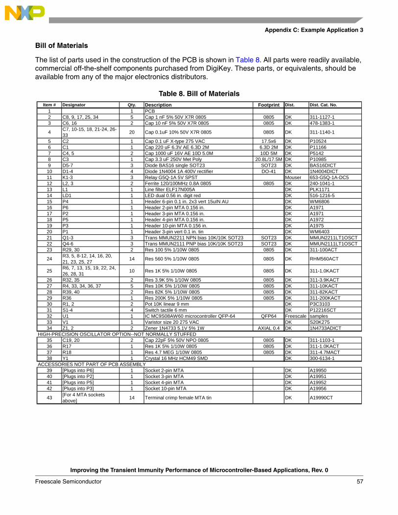
Appendix C: Example Application 3
Bill of Materials
The list of parts used in the construction of the PCB is shown in Table 8. All parts were readily available, commercial off-the-shelf components purchased from DigiKey. These parts, or equivalents, should be available from any of the major electronics distributors.
Table 8. Bill of MaterialsItem # Designator Qty. Description Footprint Dist. Dist. Cat. No.
1 1 PCB2 C8, 9, 17, 25, 34 5 Cap 1 nF 5% 50V X7R 0805 0805 DK 311-1127-13 C6, 16 2 Cap 10 nF 5% 50V X7R 0805 0805 DK 478-1383-1
4 C7, 10-15, 18, 21-24, 26-33 20 Cap 0.1uF 10% 50V X7R 0805 0805 DK 311-1140-1
5 C2 1 Cap 0.1 uF X-type 275 VAC 17.5x6 DK P105246 C1 1 Cap 220 uF 6.3V AE 6.3D 2M 6.3D 2M DK P111667 C4, 5 2 Cap 1000 uF 16V AE 10D 5.0M 10D 5M DK P51428 C3 1 Cap 3.3 uF 250V Met Poly 20.8L/17.5M DK P109859 D5-7 3 Diode BAS16 single SOT23 SOT23 DK BAS16DICT
10 D1-4 4 Diode 1N4004 1A 400V rectifier DO-41 DK 1N4004DICT11 K1-3 3 Relay G5Q-1A 5V SPST Mouser 653-G5Q-1A-DC512 L2, 3 2 Ferrite 120/100MHz 0.8A 0805 0805 DK 240-1041-113 L1 1 Line filter ELF17N005A DK PLK117114 LD1 1 LED dual 0.56 in. digit red DK 516-1216-515 P4 1 Header 6-pin 0.1 in. 2x3 vert 15uIN AU DK WM680616 P6 1 Header 2-pin MTA 0.156 in. DK A197117 P2 1 Header 3-pin MTA 0.156 in. DK A197118 P5 1 Header 4-pin MTA 0.156 in. DK A197219 P3 1 Header 10-pin MTA 0.156 in. DK A197520 P1 1 Header 3-pin vert 0.1 in. tin DK WM640321 Q1-3 3 Trans MMUN2211 NPN bias 10K/10K SOT23 SOT23 DK MMUN2211LT1OSCT22 Q4-6 3 Trans MMUN2111 PNP bias 10K/10K SOT23 SOT23 DK MMUN2111LT1OSCT23 R29, 30 2 Res 100 5% 1/10W 0805 0805 DK 311-100ACT
24 R3, 5, 8-12, 14, 16, 20, 21, 23, 25, 27 14 Res 560 5% 1/10W 0805 0805 DK RHM560ACT
25 R6, 7, 13, 15, 19, 22, 24, 26, 28, 31 10 Res 1K 5% 1/10W 0805 0805 DK 311-1.0KACT
26 R32, 35 2 Res 3.9K 5% 1/10W 0805 0805 DK 311-3.9KACT27 R4, 33, 34, 36, 37 5 Res 10K 5% 1/10W 0805 0805 DK 311-10KACT28 R39, 40 2 Res 82K 5% 1/10W 0805 0805 DK 311-82KACT29 R36 1 Res 200K 5% 1/10W 0805 0805 DK 311-200KACT30 R1, 2 2 Pot 10K linear 9 mm DK P3C310331 S1-4 4 Switch tactile 6 mm DK P12216SCT32 U1 1 IC MC9S08AW60 microcontroller QFP-64 QFP64 Freescale samples33 V1 1 Varistor size 20 275 VAC DK S20K27534 Z1, 2 2 Zener 1N4733 5.1V 5% 1W AXIAL 0.4 DK 1N4733ADICT
HIGH-PRECISION OSCILLATOR OPTION--NOT NORMALLY STUFFED35 C19, 20 2 Cap 22pF 5% 50V NPO 0805 0805 DK 311-1103-136 R17 1 Res 1K 5% 1/10W 0805 0805 DK 311-1.0KACT37 R18 1 Res 4.7 MEG 1/10W 0805 0805 DK 311-4.7MACT38 Y1 1 Crystal 16 MHz HCM49 SMD DK 300-6134-1
ACCESSORIES NOT PART OF PCB ASSEMBLY39 [Plugs into P6] 1 Socket 2-pin MTA DK A1995040 [Plugs into P2] 1 Socket 3-pin MTA DK A1995141 [Plugs into P5] 1 Socket 4-pin MTA DK A1995242 [Plugs into P3] 1 Socket 10-pin MTA DK A19956
43 [For 4 MTA sockets above] 14 Terminal crimp female MTA tin DK A19990CT
Improving the Transient Immunity Performance of Microcontroller-Based Applications, Rev. 0
Freescale Semiconductor 57

Appendix C: Example Application 3
Test Method
The demonstration board was tested for transient immunity performance in accordance with IEC 61000-4-4. The test was performed using a Haefely PEFT-4010 electrical fast transient generator.
Test Conditions
The conditions under which the testing was performed were as follows:
• All test and support equipment was installed on a grounded copper reference plane.
• The test board was located 10 cm above the grounded reference plane.
• In order to emulate a worse case wire routing scenario, all eight I/O signals from the board connector P2 were taped to the power cord over a 10 cm distance.
• The safety ground from the power cord was not utilized. It was not connected at the board.
• The power cord was coiled and held 10 cm above the grounded reference plane.
• The three relays on the PCB were connected to 15-W lamps through 45 cm lengths of wire.
Test Configuration
The tested hardware configurations are summarized below.
1. All components populated, lamps toggling, I/O wires taped parallel to power cord.
2. Same as #1 but with the following component changes: removed metal oxide varistor (V1), replaced R29 and R30 with 0 Ω resistors, removed common-mode filter (L1).
3. Same as #2 but with the following component changes: removed 220uF MCU bulk capacitor (C1), removed ferrite beads in MCU supply (L2 & L3), removed 10nF capacitors (C6 & C16).
Test Software
The test software performs the following functions:
• After reset, the LED display indicates the source of the reset condition and opens all three lamp relays. Pressing any switch starts the test software.
• Pressing switch S1 manually toggles the three relays in sequence. Repeatedly pressing the switch will cycle the relays through a repeating sequence [Relay1 ON, Others OFF -> Relay2 ON, Others OFF -> Relay3 ON, Others OFF -> All OFF].
• Pressing switch S2 toggles between manual and automatic sequencing of the relays. When the manual mode is selected, switch S1 controls the sequencing of the relays. When automatic mode is selected, the relays automatically sequence through a repeating cycle [Relay1 ON, Others OFF -> Relay2 ON, Others OFF -> Relay3 ON, Others OFF -> All OFF].
• Pressing switch S3 toggles between the available analog inputs: two potentiometers (R1 & R2) and external inputs on connector J2 (J2:1 and J2:2). The result of the analog conversion on the selected input is displayed on the LED display (LD1).
• Pressing switch S4 toggles the LED display mode between marching segments and displaying a HEX value ($00 to $FF). The speed of the marching segments or the HEX value displayed is proportional to the voltage on analog input.
Improving the Transient Immunity Performance of Microcontroller-Based Applications, Rev. 0
58 Freescale Semiconductor

Appendix C: Example Application 3
Test Results
The EFT test results are summarized in Table 9. In either of the three tested hardware configurations, the example application did not experience any detectable performance degradation. The data in the table represents the absolute value of the highest passing (non-failing) test voltage. If the value is followed by a ‘+’ sign, then this was the maximum value that could be tested with the EFT generator.
In either of the three tested hardware configurations, the example application did not experience any detectable performance degradation up to the limit of the test generator.
Table 9. Summary of EFT Test Results
HardwareConfiguration
LinePositive
[kV]
LineNegative
[kV]
NeutralPositive
[kV]
NeutralNegative
[kV]
1 4.5+ 4.5+ 4.5+ 4.5+
2 4.5+ 4.5+ 4.5+ 4.5+
3 4.5+ 4.5+ 4.5+ 4.5+
Improving the Transient Immunity Performance of Microcontroller-Based Applications, Rev. 0
Freescale Semiconductor 59

AN2764Rev. 0, 06/2005
How to Reach Us:
Home Page:www.freescale.com
E-mail:[email protected]
USA/Europe or Locations Not Listed:Freescale SemiconductorTechnical Information Center, CH3701300 N. Alma School RoadChandler, Arizona 85224+1-800-521-6274 or [email protected]
Europe, Middle East, and Africa:Freescale Halbleiter Deutschland GmbHTechnical Information CenterSchatzbogen 781829 Muenchen, Germany+44 1296 380 456 (English)+46 8 52200080 (English)+49 89 92103 559 (German)+33 1 69 35 48 48 (French)[email protected]
Japan:Freescale Semiconductor Japan Ltd.HeadquartersARCO Tower 15F1-8-1, Shimo-Meguro, Meguro-ku,Tokyo 153-0064Japan0120 191014 or +81 3 5437 [email protected]
Asia/Pacific:Freescale Semiconductor Hong Kong Ltd.Technical Information Center2 Dai King StreetTai Po Industrial EstateTai Po, N.T., Hong Kong+800 2666 [email protected]
For Literature Requests Only:Freescale Semiconductor Literature Distribution CenterP.O. Box 5405Denver, Colorado 802171-800-441-2447 or 303-675-2140Fax: [email protected]
Information in this document is provided solely to enable system and software implementers to use Freescale Semiconductor products. There are no express or implied copyright licenses granted hereunder to design or fabricate any integrated circuits or integrated circuits based on the information in this document.
Freescale Semiconductor reserves the right to make changes without further notice to any products herein. Freescale Semiconductor makes no warranty, representation or guarantee regarding the suitability of its products for any particular purpose, nor does Freescale Semiconductor assume any liability arising out of the application or use of any product or circuit, and specifically disclaims any and all liability, including without limitation consequential or incidental damages. “Typical” parameters that may be provided in Freescale Semiconductor data sheets and/or specifications can and do vary in different applications and actual performance may vary over time. All operating parameters, including “Typicals”, must be validated for each customer application by customer’s technical experts. Freescale Semiconductor does not convey any license under its patent rights nor the rights of others. Freescale Semiconductor products are not designed, intended, or authorized for use as components in systems intended for surgical implant into the body, or other applications intended to support or sustain life, or for any other application in which the failure of the Freescale Semiconductor product could create a situation where personal injury or death may occur. Should Buyer purchase or use Freescale Semiconductor products for any such unintended or unauthorized application, Buyer shall indemnify and hold Freescale Semiconductor and its officers, employees, subsidiaries, affiliates, and distributors harmless against all claims, costs, damages, and expenses, and reasonable attorney fees arising out of, directly or indirectly, any claim of personal injury or death associated with such unintended or unauthorized use, even if such claim alleges that Freescale Semiconductor was negligent regarding the design or manufacture of the part.
Freescale™ and the Freescale logo are trademarks of Freescale Semiconductor, Inc.All other product or service names are the property of their respective owners.
© Freescale Semiconductor, Inc. 2005 All rights reserved.