an2390 application note
TRANSCRIPT
August 2007 Rev 1 1/42
AN2390Application note
A flexible universal battery charger
IntroductionIn everyday life, more and more portable electronic appliances, such as mobile phones, are powered by re-chargeable batteries so the demand for battery chargers for charging these batteries is increasing all the time.
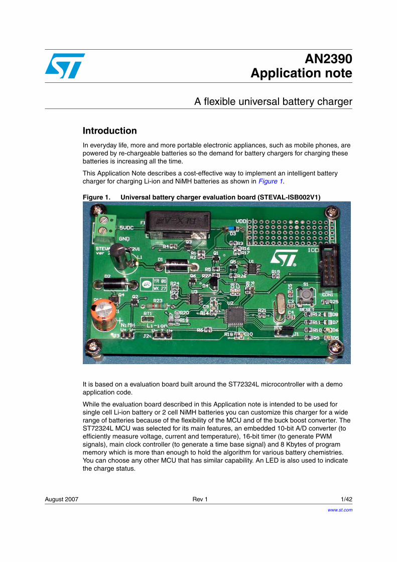
This Application Note describes a cost-effective way to implement an intelligent battery charger for charging Li-ion and NiMH batteries as shown in Figure 1.
Figure 1. Universal battery charger evaluation board (STEVAL-ISB002V1)
It is based on a evaluation board built around the ST72324L microcontroller with a demo application code.
While the evaluation board described in this Application note is intended to be used for single cell Li-ion battery or 2 cell NiMH batteries you can customize this charger for a wide range of batteries because of the flexibility of the MCU and of the buck boost converter. The ST72324L MCU was selected for its main features, an embedded 10-bit A/D converter (to efficiently measure voltage, current and temperature), 16-bit timer (to generate PWM signals), main clock controller (to generate a time base signal) and 8 Kbytes of program memory which is more than enough to hold the algorithm for various battery chemistries. You can choose any other MCU that has similar capability. An LED is also used to indicate the charge status.
www.st.com

AN2390
2/42
The evaluation board is powered from a 5 V supply. This supply is purposely chosen to show the application of the modified buck-boost converter. This is because, while a buck converter can be used to charge 2 cell NiMH battery from a 5 V supply, it is not generally suitable for charging a 4.2 V Li-ion battery due to the presence of protection diodes and other components which induce a voltage drop of around 1 V so you can not use a buck converter in this case.
The modified non-inverting buck-boost converter circuit used in this application note needs only one inductor and requires only an extra PWM signal compared to the kind of buck converter that is normally used. By using the switches in different forms, this converter can be used either as a buck converter or as a boost converter. Using the flexibility of the MCU, this converter is capable of charging a wide variety of batteries as can be seen from the evaluation board, where this converter has been used in buck converter mode to charge NiMH batteries, while a combination of buck-boost converter and boost converter modes are used to charge Li-ion batteries. For more details on the buck-boost converter, please refer to AN2389.

AN2390 Contents
3/42
Contents
1 Theory of operation . . . . . . . . . . . . . . . . . . . . . . . . . . . . . . . . . . . . . . . . . 5
1.1 Li-ion battery charging . . . . . . . . . . . . . . . . . . . . . . . . . . . . . . . . . . . . . . . . 5
1.2 NiMH battery charging . . . . . . . . . . . . . . . . . . . . . . . . . . . . . . . . . . . . . . . . 7
1.2.1 Negative delta V method . . . . . . . . . . . . . . . . . . . . . . . . . . . . . . . . . . . . . 7
1.2.2 Zero delta voltage method . . . . . . . . . . . . . . . . . . . . . . . . . . . . . . . . . . . . 7
1.2.3 Max temperature detection method . . . . . . . . . . . . . . . . . . . . . . . . . . . . . 7
1.3 Slot management . . . . . . . . . . . . . . . . . . . . . . . . . . . . . . . . . . . . . . . . . . . . 8
1.4 Man-machine interface . . . . . . . . . . . . . . . . . . . . . . . . . . . . . . . . . . . . . . . . 8
2 Evaluation board implementation . . . . . . . . . . . . . . . . . . . . . . . . . . . . . . 9
2.1 Charging circuitry . . . . . . . . . . . . . . . . . . . . . . . . . . . . . . . . . . . . . . . . . . . . 9
2.1.1 DC (Buck-Boost) converter component selection . . . . . . . . . . . . . . . . . 10
Inductor selection . . . . . . . . . . . . . . . . . . . . . . . . . . . . . . . . . . . . . . . . . . . . . . . . .10
Capacitor selection . . . . . . . . . . . . . . . . . . . . . . . . . . . . . . . . . . . . . . . . . . . . . . . .10
2.1.2 Battery discharge protection . . . . . . . . . . . . . . . . . . . . . . . . . . . . . . . . . 10
2.2 Analog measurement circuitry . . . . . . . . . . . . . . . . . . . . . . . . . . . . . . . . . 11
2.2.1 Voltage reference generation . . . . . . . . . . . . . . . . . . . . . . . . . . . . . . . . . 11
2.2.2 Current measurement . . . . . . . . . . . . . . . . . . . . . . . . . . . . . . . . . . . . . . 12
2.2.3 Voltage measurement . . . . . . . . . . . . . . . . . . . . . . . . . . . . . . . . . . . . . . 12
2.2.4 Temperature sensing . . . . . . . . . . . . . . . . . . . . . . . . . . . . . . . . . . . . . . . 13
2.2.5 Battery recognition mechanism . . . . . . . . . . . . . . . . . . . . . . . . . . . . . . . 14
Li-ion battery recognition scheme. . . . . . . . . . . . . . . . . . . . . . . . . . . . . . . . . . . . .14
NiMH battery recognition scheme . . . . . . . . . . . . . . . . . . . . . . . . . . . . . . . . . . . .14
2.2.6 Power supply restrictions . . . . . . . . . . . . . . . . . . . . . . . . . . . . . . . . . . . . 16
2.3 MCU software . . . . . . . . . . . . . . . . . . . . . . . . . . . . . . . . . . . . . . . . . . . . . . 17
2.3.1 Architecture . . . . . . . . . . . . . . . . . . . . . . . . . . . . . . . . . . . . . . . . . . . . . . 17
2.3.2 Use of the ST7 MCU on-chip peripherals . . . . . . . . . . . . . . . . . . . . . . . 19
2.3.3 State diagrams . . . . . . . . . . . . . . . . . . . . . . . . . . . . . . . . . . . . . . . . . . . . 20
3 How to use the evaluation board . . . . . . . . . . . . . . . . . . . . . . . . . . . . . . 27
3.1 Connecting the evaluation board . . . . . . . . . . . . . . . . . . . . . . . . . . . . . . . 27
3.1.1 Jumper Connections . . . . . . . . . . . . . . . . . . . . . . . . . . . . . . . . . . . . . . . 27
3.1.2 Powering and running the evaluation board . . . . . . . . . . . . . . . . . . . . . . 28
3.2 Warnings/ Limitations . . . . . . . . . . . . . . . . . . . . . . . . . . . . . . . . . . . . . . . . 28

Contents AN2390
4/42
3.3 Example test results with evaluation board . . . . . . . . . . . . . . . . . . . . . . . 28
3.3.1 Test environment . . . . . . . . . . . . . . . . . . . . . . . . . . . . . . . . . . . . . . . . . . 28
3.3.2 Li-ion battery charger . . . . . . . . . . . . . . . . . . . . . . . . . . . . . . . . . . . . . . . 29
3.3.3 NiMH battery charger . . . . . . . . . . . . . . . . . . . . . . . . . . . . . . . . . . . . . . . 31
4 Conclusion: a low-cost flexible solution . . . . . . . . . . . . . . . . . . . . . . . . 35
5 References . . . . . . . . . . . . . . . . . . . . . . . . . . . . . . . . . . . . . . . . . . . . . . . . 36
Appendix A . . . . . . . . . . . . . . . . . . . . . . . . . . . . . . . . . . . . . . . . . . . . . . . . . . . . . . . 37
A.1 Source file organization. . . . . . . . . . . . . . . . . . . . . . . . . . . . . . . . . . . . . . . 37
A.2 Schematic . . . . . . . . . . . . . . . . . . . . . . . . . . . . . . . . . . . . . . . . . . . . . . . . . 38
A.3 BOM . . . . . . . . . . . . . . . . . . . . . . . . . . . . . . . . . . . . . . . . . . . . . . . . . . . . . 39
Revision history . . . . . . . . . . . . . . . . . . . . . . . . . . . . . . . . . . . . . . . . . . . . . . . . . . . . 41
AN2390 Theory of operation
5/42
1 Theory of operation
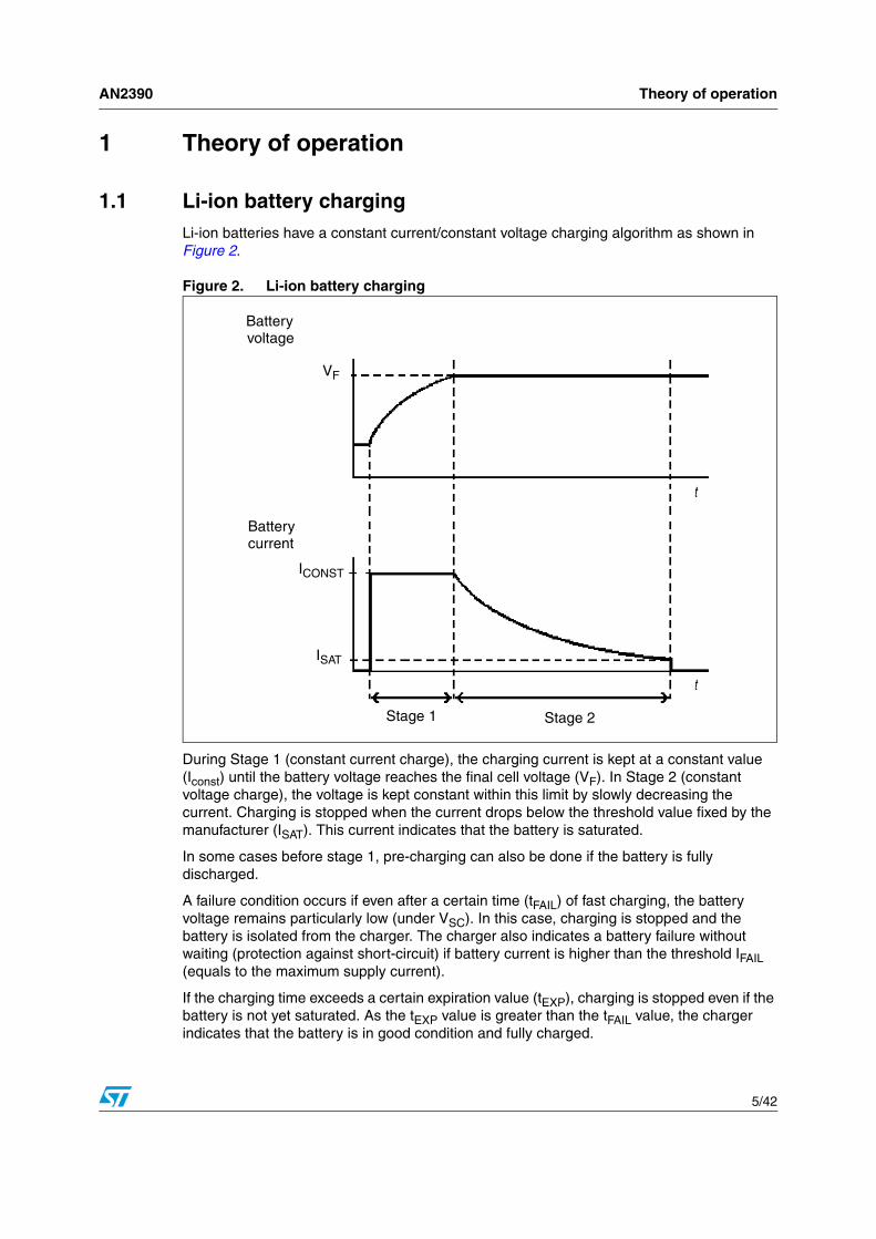
1.1 Li-ion battery chargingLi-ion batteries have a constant current/constant voltage charging algorithm as shown in Figure 2.
Figure 2. Li-ion battery charging
During Stage 1 (constant current charge), the charging current is kept at a constant value (Iconst) until the battery voltage reaches the final cell voltage (VF). In Stage 2 (constant voltage charge), the voltage is kept constant within this limit by slowly decreasing the current. Charging is stopped when the current drops below the threshold value fixed by the manufacturer (ISAT). This current indicates that the battery is saturated.
In some cases before stage 1, pre-charging can also be done if the battery is fully discharged.
A failure condition occurs if even after a certain time (tFAIL) of fast charging, the battery voltage remains particularly low (under VSC). In this case, charging is stopped and the battery is isolated from the charger. The charger also indicates a battery failure without waiting (protection against short-circuit) if battery current is higher than the threshold IFAIL (equals to the maximum supply current).
If the charging time exceeds a certain expiration value (tEXP), charging is stopped even if the battery is not yet saturated. As the tEXP value is greater than the tFAIL value, the charger indicates that the battery is in good condition and fully charged.
Stage 1 Stage 2
Battery current
voltageBattery
VF
ICONST
ISAT

Theory of operation AN2390
6/42
The battery temperature is also monitored. If the battery overheats, charging is suspended until the battery cools down.
Once the battery is saturated, its voltage is still monitored to prevent the battery from discharging completely. If the battery voltage drops below VSAT, charging restarts until VF is reached again. Charge time is reset when trickle charging starts.
Table 1. Li-ion charge parameters used in the evaluation board
Symbol Meaning Value Unit
VMAX Maximum charging voltage 4.3
V
VF Final battery voltage 4.2
VTRI Trickle charge voltage 4.12
VFAST Fast charge voltage 3.0
VSC Battery failure voltage 1.5
IFAST Fast charge current 1000
mAISAT Battery saturation current 20
IFAIL Short circuit current 1200
tFAIL Battery failure time 30 s
tEXP Charge expire time 4 h
AN2390 Theory of operation
7/42
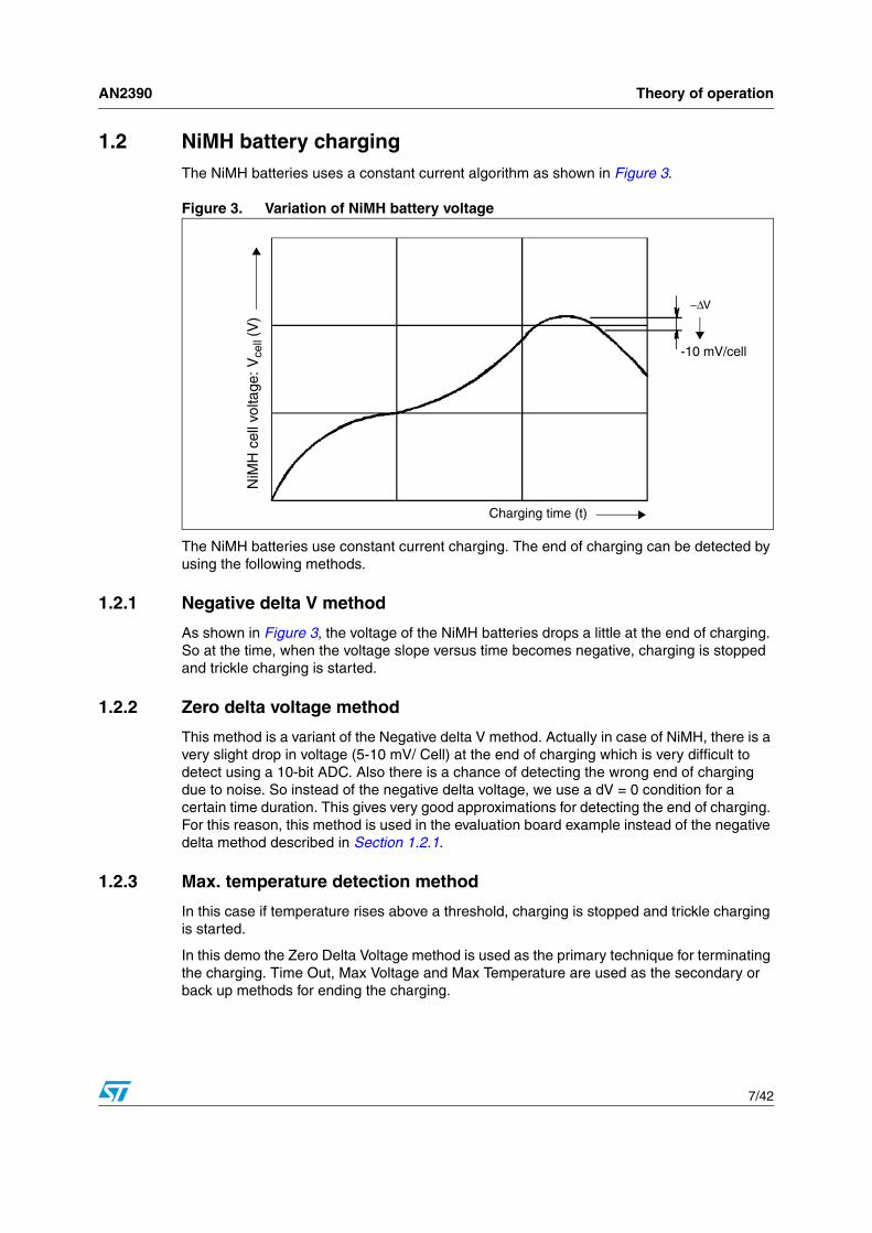
1.2 NiMH battery chargingThe NiMH batteries uses a constant current algorithm as shown in Figure 3.
Figure 3. Variation of NiMH battery voltage
The NiMH batteries use constant current charging. The end of charging can be detected by using the following methods.
1.2.1 Negative delta V method
As shown in Figure 3, the voltage of the NiMH batteries drops a little at the end of charging. So at the time, when the voltage slope versus time becomes negative, charging is stopped and trickle charging is started.
1.2.2 Zero delta voltage method
This method is a variant of the Negative delta V method. Actually in case of NiMH, there is a very slight drop in voltage (5-10 mV/ Cell) at the end of charging which is very difficult to detect using a 10-bit ADC. Also there is a chance of detecting the wrong end of charging due to noise. So instead of the negative delta voltage, we use a dV = 0 condition for a certain time duration. This gives very good approximations for detecting the end of charging. For this reason, this method is used in the evaluation board example instead of the negative delta method described in Section 1.2.1.
1.2.3 Max. temperature detection method
In this case if temperature rises above a threshold, charging is stopped and trickle charging is started.
In this demo the Zero Delta Voltage method is used as the primary technique for terminating the charging. Time Out, Max Voltage and Max Temperature are used as the secondary or back up methods for ending the charging.
NiM
H c
ell v
olta
ge: V
cell
(V)
−∆V
-10 mV/cell
Charging time (t)

Theory of operation AN2390
8/42
Once the battery is saturated, its voltage is still monitored to prevent the battery from discharging completely. If the battery voltage drops below VTRI, charging restarts until VF is reached again. Charge time is reset when trickle charging starts.
1.3 Slot managementIn the demo, there are two different kinds of slots for charging Li-ion and NiMH battery chemistries to show that it can support wide range of batteries. But the positive terminal of one slot is shorted to the positive slot of another battery and similarly for the negative terminals. So the system can support charging of only one battery at a time. Hence you must take care to connect only one battery at a time to the charger. Otherwise the batteries will be shorted together.
1.4 Man-machine interfaceThe charger periodically checks for battery presence so no button is needed to start or stop charging. An LED is used to indicate the charge status as listed in Table 3..
A reset button is also included on the evaluation board to manually reset the application.
Table 2. NiMH Charge parameters used in the evaluation board
Symbol Meaning Value Unit
VMAX Max Battery Voltage 1.7/Cell
VVTRI Trickle Charge Voltage 1.0V/Cell
VFAIL Battery Failure Voltage 0.9/Cell
ICONST Constant Charge Current 1000
mAITRICKLE_1 Initial Trickle Charging Current 250
ISAT Battery Saturation Current 65
IFAIL Short Circuit Current 1200
tINITIAL Initial Delay 10minutes
tFAIL Battery Failure Time 30
tEXP Charge Expire Time 4h
tFAST Fast Charging Time 2
Table 3. LED slot status color code
LED output Charging status
OFF No battery in the slot
Flashing @ 1 Hz Charging ongoing
Flashing @ 2 Hz Problem in charging
ON Battery Present/ Charging Complete
AN2390 Evaluation board implementation
9/42
2 Evaluation board implementation
2.1 Charging circuitryThe evaluation board implements a solution with an external low-voltage DC supply.
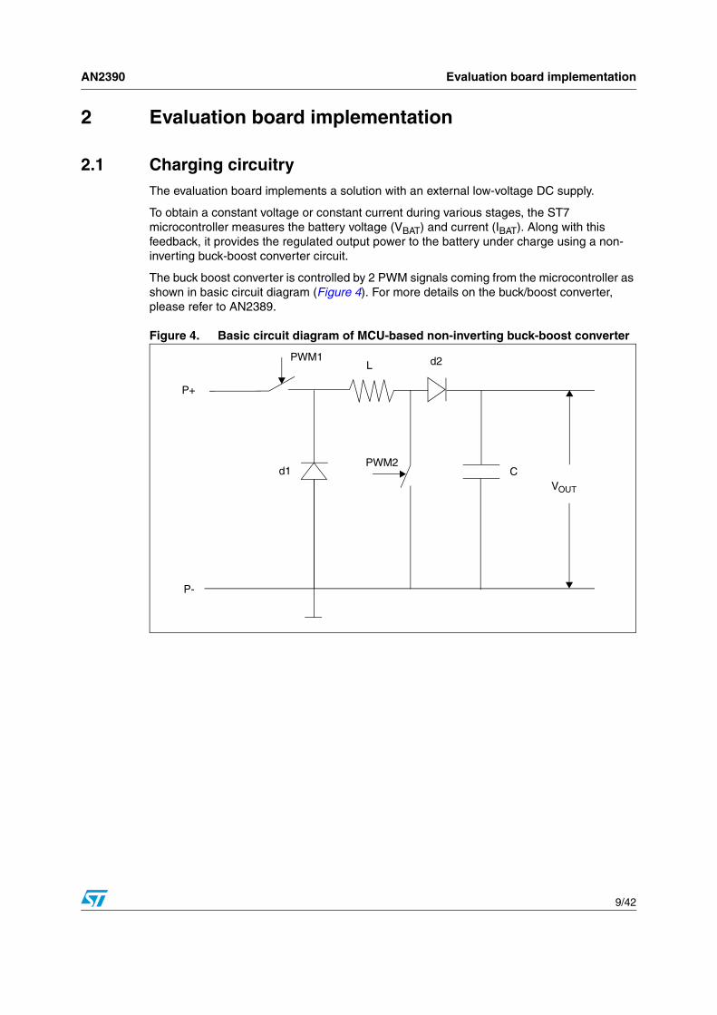
To obtain a constant voltage or constant current during various stages, the ST7 microcontroller measures the battery voltage (VBAT) and current (IBAT). Along with this feedback, it provides the regulated output power to the battery under charge using a non-inverting buck-boost converter circuit.
The buck boost converter is controlled by 2 PWM signals coming from the microcontroller as shown in basic circuit diagram (Figure 4). For more details on the buck/boost converter, please refer to AN2389.
Figure 4. Basic circuit diagram of MCU-based non-inverting buck-boost converter
PWM1
PWM2
VOUT
Cd1
P-
P+
L d2

Evaluation board implementation AN2390
10/42
2.1.1 DC (Buck-Boost) converter component selection
The value of inductor L and capacitor C are selected by the following section. For more detail please refer to AN2389.
Inductor selection
The minimum value of the inductor can be selected by choosing the maximum of the values given by the following two formulae:
Here Vsat1 and Vsat2 are the saturation voltages of the two switches Sw1 and Sw2.
Iout and Vout are the maximum output current and voltage respectively.
Vd1 and Vd2 is the voltage drop across diodes d1 and d2.
The duty cycle of the PWM signals driving switch Sw1 (PWM1) and Sw2 (PWM2) are D1 and D2 respectively.
Capacitor selection
The minimum capacitor value can be selected using the following formula to keep the variation in Vout with in 1%:
In practice we take inductor and capacitor values that are 25% more than the values calculated using the above formulae.
2.1.2 Battery discharge protection
If the charger is not powered on or if the battery is already fully charged, the PNP transistor is kept permanently off which isolates the battery from the charger. Because of series diode available in the buck-boost circuitry there is no reverse current flowing into the charger. Therefore, the battery discharges into the output capacitor and resistive bridge. This allows battery voltage measurement while consuming very little current. Also some leakage current flows through the output capacitor.
T * [ ( Vin - Vsat1) * D1 - Vsat2 * D2 - Vout * (D1 - D2))]Lmin =
2 * Iout
T * [ Vd1 + Vout] * ( 1 - D1)Lmin =
2 * Iout
100 * Iout * (1 - D1) * TCmin =
Vout
AN2390 Evaluation board implementation
11/42
2.2 Analog measurement circuitry
2.2.1 Voltage reference generation
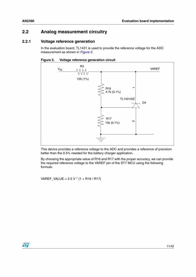
In the evaluation board, TL1431 is used to provide the reference voltage for the ADC measurement as shown in Figure 5.
Figure 5. Voltage reference generation circuit
This device provides a reference voltage to the ADC and provides a reference of precision better than the 0.5% needed for the battery charger application.
By choosing the appropriate value of R16 and R17 with the proper accuracy, we can provide the required reference voltage to the VAREF pin of the ST7 MCU using the following formula:
VAREF_VALUE = 2.5 V * (1 + R16 / R17)
21R16
4.7k (0.1%)
100 (1%)
R3
TL1431AIZ
R1715k (0.1%)
D4
VAREFVIN

Evaluation board implementation AN2390
12/42
2.2.2 Current measurement
The current measurement circuit is given in Figure 6.
Figure 6. Voltage and current measurement circuit
As shown in the above diagram, a shunt (R23) is connected in series to the battery in order to measure the charging current. The drop across this sense resistor is further amplified by using the OP-AMP (Operational Amplifier) LM258A for better resolution and this amplified voltage is measured by the ST7 microcontroller using ADC channel AIN1. The amplification factor is chosen such that the OP-AMP output has a voltage range between ground and VDD.
2.2.3 Voltage measurement
The voltage measurement circuit is also given in Figure 6 above, where the ST7 ADC channel, AIN0 is used for voltage measurement. In the evaluation board, while the input supply voltage Vsupply = 5 V, the microcontroller is supplied with VDD = 3.3 V. Therefore, it is not possible to read the battery voltage directly, but this voltage is attenuated by using a resistor bridge (R19, R20). However, this attenuation must still allow us to make full use of the whole ADC input range (0 to VDD).
Note: The ST7 MCU does not measure VBAT, it measures VB, which is proportional to (VBAT + RS* IBAT). Some calculation must be performed on the conversion results to get the actual battery voltage.
R195k (0.5%)
R205k (0.5%)
AIN0 VB
VBAT
V+
V-
AIN8
BTI LI-ION BATTERY
AIN1
R223.3k (0.5%) 13.32k (0.5%)
R24
VCC
O2
2-2+
O1
1-
1+GND
12
34
87
65
LM258AD
R23
0.5,1W (0.5%)
VIN
U3
th

AN2390 Evaluation board implementation
13/42
2.2.4 Temperature sensing
The circuit for the temperature measurement is given in Figure 7.
Figure 7. Temperature measurement circuit
For Li-ion, there is an inbuilt NTC so there is no need for an external thermistor but for NiMH, an external NTC is connected to the negative terminal of the battery.
The same measurement technique is used for both cases. Here the ST7 ADC channel AIN8 is used for the Li-ion temperature measurement and ST7 ADC channel AIN14 is used for NiMH.
For this demo application, we do not need to monitor the temperature very extensively. We only need to detect extreme hot or cold conditions. For this reason, rather than using a look-up table to calculate the temperature, certain predefined parameters are used and these parameters are compared with the temperature reading in terms of NTC resistance which simplifies the calculation.
VDDBattery
RS
ST7 analog input(AIN8 or AIN14)

Evaluation board implementation AN2390
14/42
Figure 8. NTC resistance value indication for Li-ion
Note: 1 Here Rheat corresponds to 45°C as the temperature limit for Heat Condition and Rcold corresponds to 0°C as the temperature limit for Cold condition for safe charging for both Li-ion and NiMH batteries.
2 RDET is a dummy condition to detect when no battery is in the slot. This threshold is used to detect the battery presence for Li-ion battery only. For NiMH we use a different battery recognition scheme as explained in the following section.
2.2.5 Battery recognition mechanism
In this demo, different techniques are used for Li-ion and NiMH batteries to recognize whether a battery is present in the evaluation board or not.
Li-ion battery recognition scheme
As explained in the previous section, for Li-Ion batteries, the in-built NTC thermistor is used to detect battery presence as shown in Figure 8
NiMH battery recognition scheme
In this case, there is no inbuilt NTC in the NiMH as there is in a Li-ion battery. Hence we can not use the same technique for recognizing a NiMH battery. The NiMH battery recognition circuit is shown in Figure 9.
Rdet
Rcold
Rheat
No battery present
Cold condition
Battery under normal temperature conditions
Heat condition

AN2390 Evaluation board implementation
15/42
Figure 9. NiMH battery recognition circuit
Here the combination of two transistors works as a switch which is controlled by the E_Front signal coming from the ST7 MCU. The algorithm for NiMH battery recognition is as follows.
To charger
BT2Ni-MH BATTERY
V-
V+Q5
VIN
R26470
R27470
R7
1k
Q6
E_FRONT
2STR1215
2STR1215
13
2
3 1
2

Evaluation board implementation AN2390
16/42
Figure 10. NiMH battery recognition algorithm
Here if the battery current is less than a predefined threshold, switch (Q5) as shown in Figure 9, is enabled and the battery voltage is measured if the battery voltage is lower than the certain threshold the battery is considered connected otherwise it is considered not to be connected to the evaluation board.
2.2.6 Power supply restrictions
The battery characteristics have a direct influence on the choice of the DC power supply. The supply must be able to drive enough current to charge the battery, even in fast charge mode.
● VSUPPLY must be larger than (VCE|SAT + Vdiode + VBAT_MAX + RS* ICONST).
Also the MCU, Buck-Boost DC-DC converter, LED and OpAmp consumption must be taken into account as well. RS is the sense resistor, indicated as R23 in Figure 6.
In this demo, a DC supply providing 5 V and 2 A is chosen which is sufficient to satisfy the above condition.
NiMH BATTRecog Algo
NO Exit
YES
ENABLE THE SWITCH AND MEASURE THE BATTERY
VOLTAGE
IF (IBAT > IOPEN)
NO
BATTERY NOT PRESENT
YES
END
BATTERY PRESENTIF (VBAT > VOPEN)

AN2390 Evaluation board implementation
17/42
2.3 MCU software
2.3.1 Architecture
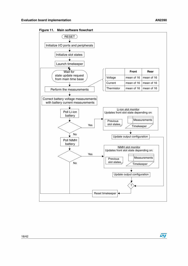
The software provided in this demo has state machine architecture. To explain more, various charging states can be defined for each slot. Each slot is driven by its state machine, with some interactions to implement front slot priority.
In order to measure the charge time, a timekeeper is implemented and counters are incremented periodically. Most of the time, slot states are unchanged. This implies that the PWM duty cycle, charge enable signals and LED on/off states are constant. Periodically, the ST7 microcontroller measures the battery current, battery voltage and thermistor voltage of both slots. Using the measurements and the timekeeper values, it updates slot states and the output configuration. If necessary, it resets the timekeeper.
Evaluation board implementation AN2390
18/42
Figure 11. Main software flowchart
RESET
Initialize I/O ports and peripherals
Launch timekeeper
Initialize slot states
Wait for state update requestfrom main time base
Perform the measurements
Correct battery voltage measurements with battery current measurements
Poll Li-ionbattery
Poll NiMHbattery
Front Rear
Voltage mean of 16 mean of 16
Current mean of 16 mean of 16
Thermistor mean of 16 mean of 16
Li-ion slot monitorUpdates front slot state depending on:
Previousslot states
Measurements
Timekeeper
Update output configuration
NiMH slot monitorUpdates front slot state depending on:
Previousslot states
Measurements
Timekeeper
Update output configuration
?
Reset timekeeper
Yes
Yes
No
No

AN2390 Evaluation board implementation
19/42
2.3.2 Use of the ST7 MCU on-chip peripherals
The time base is generated using the Main Clock Controller and the PWM is generated by the 16-bit timer. In order to minimize supply current, the ST7 core puts itself into WAIT mode between two state updates which is updated @50 ms for Li-ion and @5 s for NiMH but the PWM duty cycle for both is updated @50 ms. The reason for keeping the state update high for NiMH is to detect the end of charging conditions properly which requires monitoring the voltage difference (Zero Delta Voltage Condition) for a long period of time, keeping a low value might result in wrong detection. The selection of state update request for NiMH depends on the user application.
In this demo, the same interrupt condition (Timer reaching zero) also increments the timekeeper counters. This means the timekeeper is synchronized with the state updates.
The timekeeper divides the standard timer frequency. To do this, it has three counters: tick, timeKeeper_Low and timeKeeper_Hi.
The analog to digital converter (ADC) is used intensively before each slot state update. In most cases, the PWM output cannot be disabled, so due to switching noise, the ADC accuracy is not optimal. To reduce errors, the ADC measures battery voltage, battery current and battery temperature 16 times in a row and takes the average as the final value. The software is able to remove any spurious errors due to noise to avoid any wrong interpretations. The slot state monitoring software works with the mean values.
As explained earlier, battery voltage measurements must be corrected with battery current measurements. These corrections require some computing, performed on the 16-bit words.
Table 4. Charge timekeeper counters
tick timeKeeper_Low timeKeeper_hi
Increment Condition Timer Zero IT tick = 0 timeKeeper_Low = 0
Period
General TTMZ 125 * TTMZ 60,000 * TTMZ
Evaluation board
2 ms 250 ms 1 min
Evaluation board implementation AN2390
20/42
2.3.3 State diagrams
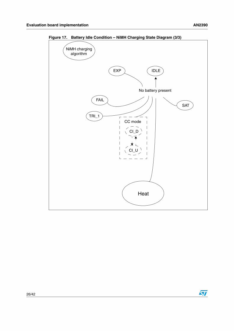
A slot can be in one of the nine states as described in following table. These states are updated periodically as described earlier in Section 2.3.1
It is important to understand that this choice of states is only one solution and that there are many possible ways to manage the behavior of the charger.
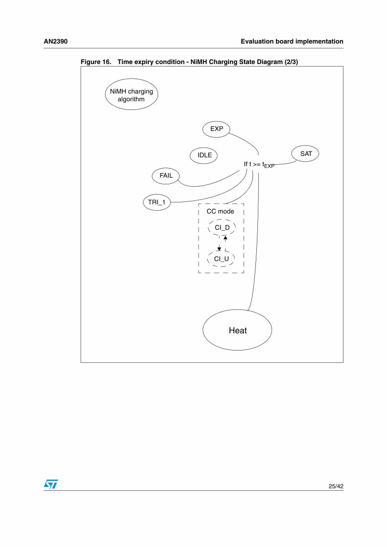
The state transition diagram is too complex to be shown in a single figure, it has been divided into six parts shown in Figure 12 through Figure 17. In the diagrams, 't' stands for the timekeeper value. The rectangles represent actions performed once during a state transition.
Table 5. Slot state definitions
Name MeaningOutput configuration
Slot outputs PWM duty cycle
IDLE Slot emptyCharge disabled,
LEDs off Unchanged
TRI_1 1st Trickle charge stateCharge enabled,
LED blinking @ 1HzUpdated periodically to
have Ibat = Itri_1
CI Constant current chargeUpdated periodically to
have Ibat = Iconst
CVConstant voltage charge,
duty cycle downUpdated periodically to
have Vbat = VF
TRI_2 2nd Trickle charge stateUpdated periodically to
have Ibat = Itri_2
SAT Battery saturated Charge disabled,LED ON
Unchanged
EXP Charge time expired
FAIL Battery failureCharge disabled,
LED blinking @ 2HzHEATCharge suspended
by overheat

AN2390 Evaluation board implementation
21/42
Figure 12. General charging flow – Li-ion charging state diagram (1/3)
Heat
Li-ion charging algorithm EXP
IDLE
TRI_2
TRI_1
SAT
CI_D
CI_U
CC mode
CV_D
CV_U
CV mode
If VBAT > VF
If IBAT > ISAT
If VBAT < VSAT
If VBAT > VF
Suspend PWM until it gets to normal condition
Trickle charging to maintaincurrent = 0.2C
FAIL
If (IBAT > IFAIL) OR if (VBAT < VSC AND t > tFAIL)
If VBAT > VFAST

Evaluation board implementation AN2390
22/42
Figure 13. Time expiry condition – Li-ion charging state diagram (2/3)
Heat
Li-ion charging algorithm EXPIDLE
FAIL
TRI_2
TRI_1
SAT
CI_D
CI_U
CC mode
CV_D
CV_U
CV mode
If t >= tEXP

AN2390 Evaluation board implementation
23/42
Figure 14. Battery Idle condition – Li-ion charging state diagram (3/3)
Heat (Suspend
IDLE
FAIL
TRI_1
EXP or SAT
CI_D
CI_U
CC mode
CV_D
CV_U
CV mode
No battery present
PWM)

Evaluation board implementation AN2390
24/42
Figure 15. General charging flow – NiMH charging state diagram (1/3)
Heat
NiMH charging algorithm EXP
IDLEFAIL
TRI_1
SAT
CI_D
CI_U
CC mode
If (dV/dt for timeCheck)
Suspend PWM
Trickle charging to maintaincurrent = 0.2C,
If VBAT > V
TRI
no -dV checking Trickle charging to keep current = 0.033C to 0.05C
Or, if VBAT > VMAXOr, if (t > tFAST)
If (IBAT > IFAIL) OR if (VBAT < VFAIL AND t > 30 min)
AN2390 Evaluation board implementation
25/42
Figure 16. Time expiry condition - NiMH Charging State Diagram (2/3)
Heat
NiMH charging algorithm
EXP
IDLE
FAIL
TRI_1
CI_D
CI_U
CC mode
If t >= tEXP
SAT
Evaluation board implementation AN2390
26/42
Figure 17. Battery Idle Condition – NiMH Charging State Diagram (3/3)
Heat
NiMH charging algorithm
EXP IDLE
FAIL
TRI_1
CI_D
CI_U
CC mode
SAT
No battery present

AN2390 How to use the evaluation board
27/42
3 How to use the evaluation board
3.1 Connecting the evaluation board
3.1.1 Jumper Connections
The following jumpers must be correctly configured for proper operation of the evaluation board.
J1: This is a 3-pin connector for selecting between ICC clock and resonator clock.
Figure 18. ICC connector
ICC clock is used only when we need to re-program the ST7 microcontroller. For normal operation please short pin 1 and pin 2.
J2, J3: These jumpers are used to connect charger slots for different batteries as shown in Figure 19.
Figure 19. J2 and J3 connections
1 2 3
EXT OSC1 ICC_OSC
J1
2-CELL NiMH
BATTERY CHARGER SLOT
UNIVERSAL BATTERY
CHARGER
RT1: NTCCONNECTOR
J2 CONNECTOR FOR NiMHV+ V-
J3 CONNECTOR FOR Li-ION
V+ T V-
1-CELL Li-ION
BATTERY CHARGER SLOT
Put NTC close to slot

How to use the evaluation board AN2390
28/42
The role of each jumper is as follows:
J2: Used to connect NiMH Battery Charger Slot
J3: Used to connect NiMH Battery Charger Slot
RT1: RT1 is used to connect external NTC. This NTC is put close to the NiMH charger slot to correctly monitor the NiMH battery temperature.
3.1.2 Powering and running the evaluation board
After all the jumpers are connected as described in Section 3.1.1, you can connect the power supply. To connect the power supply there is a power jack X1 (5V, Gnd) available on the evaluation board. You need to connect a DC power supply of (5V, 2A) to this connector.
After connecting the power supply, you need to press the Reset button on the evaluation board for correct operation.
Now the evaluation board is in running mode and you can monitor the charging status through LED D5 status as mentioned in Table 3.
Note: It is necessary to press the Reset button once after connecting the power supply as the LVD feature is not used in this evaluation board. However the LVD can be implemented in a real application
3.2 Warnings/ LimitationsThe user should be aware of the following warnings/limitations when using this evaluation board.
1. Only one type of battery can be charged at a time and there is no protection to prevent shorting the batteries if they are connected simultaneously in both slots. So the user has to make sure to connect only one battery at a time.
2. There is no protection for reverse battery polarity connection but it can be provided on customer request.
3. To minimize noise spikes at the input power supply, please connect a capacitor of 100 - 220 uF between the input power supply and Gnd.
3.3 Example test results with evaluation board
3.3.1 Test environment
In this implementation of the buck-boost converter, the following values are taken into account.
Transistor drop |VCE| (SAT) = 0.2V, Diode drop |Vd| = 0.55 V, L = 75 mH, C = 470 uF, Max Vsense = 0.5V, Fcpu = 8 MHz, Fpwm = 16 kHz and Ambient Temperature = 24 deg C. Also the timer is updated at 500 Hz.

AN2390 How to use the evaluation board
29/42
3.3.2 Li-ion battery charger
The following parameter values are used in the Li-ion charger:
The following values are programmed for the different phases:
1) Precharge Phase:
Here Vbat <= 3.0 V and charging current: 200 mA
2) Constant Current Phase:
Here 3.0 < Vbat < 4.2 V and charging current: 500 mA
3) Constant Voltage Phase:
Here 4.15< Vbat < 4.2 V
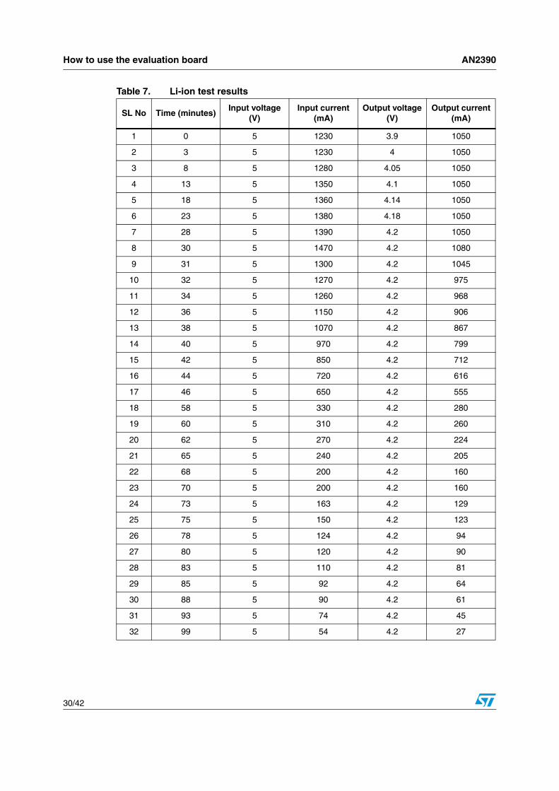
Table 9 shows the results of an experiment with the evaluation board charging a single Li-ion battery.
Table 6. Li-ion battery charger parameters
SL No Parameter name Value
Input Parameter
1 Input Supply Voltage 5 V
2 Max Input Supply Current 2A
Output Parameter
3 Max Battery Output Voltage 4.2V
4 Max Output Current 1000 mA
How to use the evaluation board AN2390
30/42
Table 7. Li-ion test results
SL No Time (minutes)Input voltage
(V)Input current
(mA)Output voltage
(V)Output current
(mA)
1 0 5 1230 3.9 1050
2 3 5 1230 4 1050
3 8 5 1280 4.05 1050
4 13 5 1350 4.1 1050
5 18 5 1360 4.14 1050
6 23 5 1380 4.18 1050
7 28 5 1390 4.2 1050
8 30 5 1470 4.2 1080
9 31 5 1300 4.2 1045
10 32 5 1270 4.2 975
11 34 5 1260 4.2 968
12 36 5 1150 4.2 906
13 38 5 1070 4.2 867
14 40 5 970 4.2 799
15 42 5 850 4.2 712
16 44 5 720 4.2 616
17 46 5 650 4.2 555
18 58 5 330 4.2 280
19 60 5 310 4.2 260
20 62 5 270 4.2 224
21 65 5 240 4.2 205
22 68 5 200 4.2 160
23 70 5 200 4.2 160
24 73 5 163 4.2 129
25 75 5 150 4.2 123
26 78 5 124 4.2 94
27 80 5 120 4.2 90
28 83 5 110 4.2 81
29 85 5 92 4.2 64
30 88 5 90 4.2 61
31 93 5 74 4.2 45
32 99 5 54 4.2 27

AN2390 How to use the evaluation board
31/42
The total time was around 99 minutes in which the constant current phase remained for around 30 minutes. Figure 20 shows the graph of the output current versus time.
Figure 20. Output Current vs. Time
The variation in the output current was around +/- 10mA and the variation in output voltage was +/- 20 mV.
3.3.3 NiMH battery charger
The following parameter values are used for the NiMH charger.
The following values are programmed for the different phases:
1) Pre-charging Phase:
Here Vbat <= 1.0 V and charging current: 0.1 C = 200 mA
Charging time taken by the battery: 10 minutes (approximately)
2) Constant Current Phase:
Charging Current = 1 A and Programmed charging time = 2 Hr
Output Current (mA) Vs Time (Minutes)
0
200
400
600
800
1000
1200
0 13 28 32 38 44 60 68 75 83 93
Time (Minutes)
Cur
rent
(mA
)
Table 8. Table 8: NiMH battery charger parameters
SL No Parameter name Value
Input Parameter
1 Input Supply Voltage 5 V
2 Max Input Supply Current 2 A
Output Parameter
3 Max Battery Output Voltage 1.7 V / cell
4 Output Current 1000 mA

How to use the evaluation board AN2390
32/42
3) Saturation Phase:
Charging Current = 0.03 C = 60 mA, and Expiry Time = 4 Hr.
In this case the C rate is 1000 mA. After the expiry time is over, charging is stopped till a new battery is inserted.
Table 9 shows the results of an experiment for constant current charging phase for a 2 Cell NiMH battery charger.

AN2390 How to use the evaluation board
33/42
The variation in the output current was around +/- 10 mA and the variation in output voltage was +/- 20 mV. Figure 21 shows the graph of the output current versus time.
Table 9. NiMH test results
SL No Time (minutes)Input voltage
(V)Input current
(A)Output voltage
(V)Output current
(mA)
1 0 5 1.01 3.16 1015
2 5 5 1.01 3.165 1015
3 10 5 1.01 3.168 1015
4 15 5 1.01 3.172 1015
5 20 5 1.01 3.168 1015
6 25 5 1.01 3.16 1015
7 30 5 1.01 3.168 1015
8 35 5 1.03 3.172 1015
9 40 5 1.03 3.175 1015
10 45 5 1.03 3.186 1015
11 50 5 1.03 3.2 1015
12 55 5 1.03 3.206 1015
13 60 5 1.03 3.214 1015
14 65 5 1.03 3.223 1015
15 70 5 1.03 3.231 1015
16 75 5 1.03 3.245 1015
17 80 5 1.05 3.252 1015
18 85 5 1.05 3.264 1015
19 90 5 1.05 3.282 1015
20 95 5 1.05 3.3 1015
21 100 5 1.08 3.35 1020
22 105 5 1.08 3.4 1020
23 110 5 1.08 3.38 1020
24 115 5 1.08 3.37 1020
25 120 5 1.08 3.37 1020
26 125 5 1.08 3.37 1020
27 130 5 1.08 3.36 1020
How to use the evaluation board AN2390
34/42
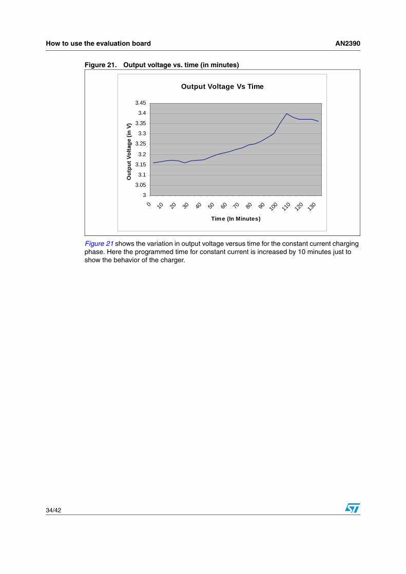
Figure 21. Output voltage vs. time (in minutes)
Figure 21 shows the variation in output voltage versus time for the constant current charging phase. Here the programmed time for constant current is increased by 10 minutes just to show the behavior of the charger.
Output Voltage Vs Time
3
3.05
3.1
3.15
3.2
3.25
3.3
3.35
3.4
3.45
0 10 20 30 40 50 60 70 80 90 100
110
120
130
Time (In Minutes)
Out
put V
olta
ge (i
n V)

AN2390 Conclusion: a low-cost flexible solution
35/42
4 Conclusion: a low-cost flexible solution
Everything on the evaluation board has been designed to make it easy to adapt in any way (to other types of battery, new behavior specifications, additional design constraints, etc.).
● The demo is developed with an ST72324L microcontroller device but you can choose another MCU device if you so desire.
● Because of the flexibility of the MCU, you can modify the firmware for wide variety of applications and this is well supported by the flexible non inverting buck boost converter which can adapt to different supply voltages. For example, you could easily make a USB charger to charge a 4.2 V Li-ion battery.
● The firmware is developed in ‘C’ language. So it is easily upgradeable.
● The number of components needed for each slot (charging and feedback) is minimal, so replacing them is inexpensive.
● The code size is approximately 3 Kbytes. The current firmware supports Li-ion and NiMh battery chemistry but it can be easily converted to charge other battery chemistries, for example to charge SLA batteries.
● ST’s low cost PNP and NPN transistors and diodes are used to implement this converter which makes it even more cost-effective.

References AN2390
36/42
5 References
[1] AN2389: “An MCU-based low cost non-inverting buck-boost converter for battery chargers”, STMicroelectronics

AN2390
37/42
Appendix A
A.1 Source file organizationThe code is written in ‘C’ language. The Code Size is approximately 3 Kbytes. The source code consists of 3 source files and 3 header files as listed below:
● main.c: it consists of the main subroutine.
● BC_func.c: These files contain the definitions of all the functions used in the main subroutine.
● Interrupt_vector.c: it consists of the interrupt vector mapping files.
● BC_func.h: it consists of the declarations of all the global variables and the functions used in the main.
● ST7lib_config.h: It is the configuration file and also consists of the #define statements for assembly language instructions like ‘NOP’ etc.
● st7lites2_5_reg.h: It contains the declarations of the hardware registers.
This modular organization makes it easier to perform minor modifications to the software.
Table 10. Examples of minor software modifications
If you want to change… …only modify…
Voltage thresholds
BC_Func.hPWM frequency
State update frequency
Timing thresholds
I/O Configuration BC_InititalizePeripheral() in BC_Func.c
State diagram
BC_SlotMonitor() function in BC_Func.cState definitions
Transition conditions
Transition priority

AN2390
38/42
A.2 Schematic
12
34
56
78
ABCD
87
65
43
21
D C B A
Scal
eSh
eet
Size
FCSM
No.
DW
GN
o.R
ev
1of
1
A3
1
STM
icro
elec
tron
ics
PvtL
tdPl
otno
.1,K
now
ledg
ePa
rkII
I,G
reat
erN
oida
-201
308,
UP
IND
IA
UN
IVE
RSA
L_B
ATT
_CH
AR
GE
R
L1
75uH
/100
0mA
C6 2.
2uF
/16V
C5
10nF
R19
5k(0
.5%
)
R20
5k(0
.5%
)
R8 1k
R22
3.3k
(0.5
%)
R21
4.7k
R9
470
R24
13.3
2k(0
.5%
)C
147
0uF/
16V
Uni
vers
alB
atte
ryC
harg
er
VD
D
BT
2
R23
0.5,
1W(0
.5%
)
t
RT
1
4.7k
/NT
C
E_F
RO
NT
D5
LE
D
D6
LE
D
D7
LE
D
D8
LE
D
R10
470
R11
470
R12
470
AIN
1
E_FRONT
PWM-1
PWM
-1
LE
D1
LE
D2
LE
D3
LE
D4
AIN
8
AIN
14
VD
D
S1
VD
D
AIN
0
2
3 1
Q1
2ST
R12
15
R2
100
R1
330
Vsu
pply
R5
470
D1
1N58
21V
in
PWM-2
R4
100
R6
1k
LED1
PWM
-2
R3
100
(1%
)
R17
15k
(0.1
%)
R16
4.7k
(0.1
%)
1 2
3D
4T
L14
31A
IZ
VA
RE
F
D2
1N58
21
12
34
56
78
910
CO
N1
HE
AD
ER
5X2
GN
D
OSC1
VD
DIC
CSE
L
ICC
DA
TA
ICC
CL
KR
ESE
TR
25
10k
ICC
V+
AIN
8V
-
V+
V-
Y1
16M
Hz
C3 33
pF
C4 33
pF
OSC
_EX
T
OSC
2
123
J1
OSC
_EX
T
V+
V-
V-
Li-I
ON
BA
TT
ER
Y
Ni-M
HB
AT
TE
RY
Li-I
ON
BA
TT
ER
Y
Ni-M
HB
AT
TE
RY
th
BT
1
VD
D
AIN
8
LE
D2
LE
D3
LE
D4
AIN0
AIN14
GN
D
VDD
GN
DV
AR
EF
RE
SET
OSC
1O
SC2
R14
10k
(1%
)
R18
4.7k
(1%
)
ICC
SEL
ICCDATA
ICCCLK
1
2 3
Q4
2ST
F136
0
C1
C2
B3
E4
C5
C6
Q3
STT
818B
O1
1
1-2
1+3
GN
D4
2+5
2-6
O2
7V
CC
8U
3
LM
258A
D
Vou
t1
GN
D2
GN
D3
NC
4IN
HIB
IT5
GN
D6
GN
D7
Vin
8U
1
KF3
3BD
TR
(HS)/PB430
PDO31PD1
32
PB028
PF7
7
PB329
PE026
VDD25 O
SC1
24
OSC
223
VSS
22
RE
SET
21
ICC
SEL
20
PA7
19
PA6
18
PA4
17
PE127
PC0
8
PC19
PC2 10
PC311
PC412
PC513
PA316
VA
RE
F1
VSS
2
AIN
8/PF
03
PF1
4
AIN
10/P
F45
PF6
6
PC715
PC6 14
U2
ST72
F324
LK
2T6
R15
10k
13
2
Q5
2ST
R22
15
R7
1k
1 2 3
J2
1 2
J3
D3
IN41
48
Vin
Vin
2
3 1Q
22S
TR
1215
R13
68
Vsu
pply
C2
100n
F(N
otT
oB
eM
ount
ed)
AIN1
VD
D
F1 FUSE
2
C7 10
0nF
AIN
0
C8 10
0nF
AIN
1
C9 10
0nF
AIN
8
C10 10
0nF
AIN
14
2
3 1
Q6
2ST
R12
15
R26
470
R27
470
1 2
X1

AN2390
39/42
A.3 BOM
Table 11. Bill of material
Index Qty ReferenceValue / Generic
Part NumberPackage
Manufacturer
Manufacturer’s ordering code / Recordable Part
Number
1 1 C1 470uF/16V RB-.2/.4 Any
2 6C3, C4, C7, C8, C9, C10
100nF 805 Any
3 1 C6 2.2 uF/ 16V 805 Any
4 1 C5 10nF 805 Any
5 1 CON1 HEADER 5X2 IDC-10B Any
6 2 D1, D2 1N5821DO-
201ADST 1N5821
7 1 D3 IN4148DO-35-
THAny
8 2 D4 TL1431 TO-92 ST TL1431AIZ
9 4D5, D6, D7,
D8LED LED Any
10 1 F1 FUSE2 FUSE Any
11 1 J1 CON3 SIP-3 Any
12 1 J2 CON3 SIP-3 Any
13 1 J3 CON2 SIP-2 Any
14 1 L1 75uH/1000mA IND Any
15 3 Q1, Q2, Q6 2STR1215 SOT-23 ST 2STR1215
16 1 Q3 STT818BSOT23-
6LST STT818B
17 1 Q4 2STF1360 SOT-89 ST 2STF1360
18 1 Q5 2STR2215 SOT-23 ST 2STR2215
19 1 R1 330 805 Any
20 7R5, R9, R10,
R11, R12, R26, R27
470 805 Any
21 1 R13 68 805 Any
22 2 R14, R15 10k (1%) 805 Any
23 1 R16 4.7k (0.1%) 805 Any
24 1 R17 15k (0.1%) 805 Any
25 1 R18 4.7k (1%) 805 ST
26 2 R19, R20 5k (0.5%) 805 Any
27 1 R2, R7 100 805 Any

AN2390
40/42
28 1 R21 4.7k 805 Any
29 1 R22 3.3k (0.5%) 805 Any
30 1 R23 0.5, 1W (0.5%) RES Axail Any
31 1 R24 13.32k (0.5%) 805 Any
32 1 R25 10k 805 Any
33 1 R3 100 (1%) 805 Any
34 1 R4 100 805 Any
35 3 R6, R8 1k 805 Any
36 1 RT1 4.7k/NTC RAD-0.1 Any
37 1 S1 SW-PB PUSH Any
38 1 U1 KF33 SO-8 ST KF33BDTR
39 1 U2 ST72F324L TQFP-32 ST ST72F324LK2T6
40 1 U3 LM258AD SO-8 ST LM258AD
41 1 X1Power
ConnectorEuro 2 pin Any
42 1 Y1 16MHz XTAL-1 Any
Table 11. Bill of material
Index Qty ReferenceValue / Generic
Part NumberPackage
Manufacturer
Manufacturer’s ordering code / Recordable Part
Number

AN2390 Revision history
41/42
Revision history
Table 12. Document revision history
Date Revision Changes
21-Aug-2007 1 Initial release.
AN2390
42/42
Please Read Carefully:
Information in this document is provided solely in connection with ST products. STMicroelectronics NV and its subsidiaries (“ST”) reserve theright to make changes, corrections, modifications or improvements, to this document, and the products and services described herein at anytime, without notice.
All ST products are sold pursuant to ST’s terms and conditions of sale.
Purchasers are solely responsible for the choice, selection and use of the ST products and services described herein, and ST assumes noliability whatsoever relating to the choice, selection or use of the ST products and services described herein.
No license, express or implied, by estoppel or otherwise, to any intellectual property rights is granted under this document. If any part of thisdocument refers to any third party products or services it shall not be deemed a license grant by ST for the use of such third party productsor services, or any intellectual property contained therein or considered as a warranty covering the use in any manner whatsoever of suchthird party products or services or any intellectual property contained therein.
UNLESS OTHERWISE SET FORTH IN ST’S TERMS AND CONDITIONS OF SALE ST DISCLAIMS ANY EXPRESS OR IMPLIEDWARRANTY WITH RESPECT TO THE USE AND/OR SALE OF ST PRODUCTS INCLUDING WITHOUT LIMITATION IMPLIEDWARRANTIES OF MERCHANTABILITY, FITNESS FOR A PARTICULAR PURPOSE (AND THEIR EQUIVALENTS UNDER THE LAWSOF ANY JURISDICTION), OR INFRINGEMENT OF ANY PATENT, COPYRIGHT OR OTHER INTELLECTUAL PROPERTY RIGHT.
UNLESS EXPRESSLY APPROVED IN WRITING BY AN AUTHORIZED ST REPRESENTATIVE, ST PRODUCTS ARE NOTRECOMMENDED, AUTHORIZED OR WARRANTED FOR USE IN MILITARY, AIR CRAFT, SPACE, LIFE SAVING, OR LIFE SUSTAININGAPPLICATIONS, NOR IN PRODUCTS OR SYSTEMS WHERE FAILURE OR MALFUNCTION MAY RESULT IN PERSONAL INJURY,DEATH, OR SEVERE PROPERTY OR ENVIRONMENTAL DAMAGE. ST PRODUCTS WHICH ARE NOT SPECIFIED AS "AUTOMOTIVEGRADE" MAY ONLY BE USED IN AUTOMOTIVE APPLICATIONS AT USER’S OWN RISK.
Resale of ST products with provisions different from the statements and/or technical features set forth in this document shall immediately voidany warranty granted by ST for the ST product or service described herein and shall not create or extend in any manner whatsoever, anyliability of ST.
ST and the ST logo are trademarks or registered trademarks of ST in various countries.
Information in this document supersedes and replaces all information previously supplied.
The ST logo is a registered trademark of STMicroelectronics. All other names are the property of their respective owners.
© 2007 STMicroelectronics - All rights reserved
STMicroelectronics group of companies
Australia - Belgium - Brazil - Canada - China - Czech Republic - Finland - France - Germany - Hong Kong - India - Israel - Italy - Japan - Malaysia - Malta - Morocco - Singapore - Spain - Sweden - Switzerland - United Kingdom - United States of America
www.st.com