an1188: efp01 coulomb counting - silicon labs
TRANSCRIPT

AN1188: EFP01 Coulomb Counting
This application note describes the configuration, calibration, andoperation of the Coulomb counter on the EFP01 Energy FriendlyPower Management IC (PMIC). The integrated Coulomb countercan losslessly measure the charge drawn from each DCDC andLDO. A software example demonstrating the Coulomb countingfeature is included in this application note.
KEY POINTS
• Ability to losslessly measure charge drawnfrom each DCDC and LDO.
• Internally integrated calibration registersfor accurate calibration.
• Example C-code• Multiple IDE projects
silabs.com | Building a more connected world. Rev. 0.3
1. Device Compatibility
This application note supports the EFP01 Energy Friendly PMIC product family.
The EFP01 devices consist of:• EFP0101• EFP0102• EFP0103• EFP0104• EFP0106• EFP0107• EFP0108• EFP0109• EFP0110• EFP0111
AN1188: EFP01 Coulomb CountingDevice Compatibility
silabs.com | Building a more connected world. Rev. 0.3 | 2
2. System Overview
2.1 Introduction
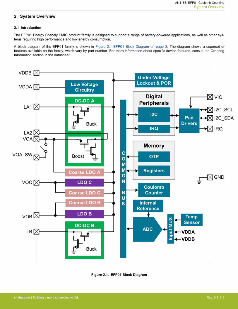
The EFP01 Energy Friendly PMIC product family is designed to support a range of battery-powered applications, as well as other sys-tems requiring high performance and low energy consumption.
A block diagram of the EFP01 family is shown in Figure 2.1 EFP01 Block Diagram on page 3. The diagram shows a superset offeatures available on the family, which vary by part number. For more information about specific device features, consult the OrderingInformation section in the datasheet.
Memory
DC-DC B
DC-DC A
Buck
Boost
Buck
VOA
VOA_SW
VOC
VOB
LB
LA2
LA1
VDDA
VDDB
ADC VDDA
Internal Reference
I2C_SCL
VIO
VDDB
I2C_SDA
IRQ
Digital Peripherals
I2C
IRQ
Registers
OTP
Coulomb Counter
Inpu
t MU
XGND
Low Voltage Circuitry
LDO B
Coarse LDO A
COMMON
BUS
LDO C
Coarse LDO C
Coarse LDO B
Temp Sensor
Under-Voltage Lockout & POR
PadDrivers
Figure 2.1. EFP01 Block Diagram
AN1188: EFP01 Coulomb CountingSystem Overview
silabs.com | Building a more connected world. Rev. 0.3 | 3
2.2 Power Modes
The EFP01 can provide up to three voltage rails for EFR32 and EFM32 devices from a single input supply voltage.
The EFP01 has two independent DCDC converters: DCDC A and DCDC B, each requiring an external inductor. DCDC A can use buck/boost, wired buck, or wired boost configurations, while DCDC B only supports buck configuration.
In addition, the EFP01 has two integrated LDOs supplied from the VDDB pin: LDO B and LDO C. LDO B is internally wired in parallelwith DCDC B. LDO C can be used independently, or it can be externally wired in parallel with DCDC A.
Finally, each EFP01 output (VOA, VOB, VOC) has its own coarse regulator in parallel for use in EM4. The coarse regulators have verylow quiescent current draw, but have poor output regulation (e.g., the output may range from ~1.7 to 3.4 V) and can only support verylight loads (~100 μA).
2.3 Energy Modes
The EFP01 operates in 3 different energy modes to optimize efficiency based on the expected load: EM0, EM2, and EM4. The Cou-lomb counter is available in EM0 and EM2 modes. In EM4 mode, all DCDCs and LDOs are disabled, and the load is powered by thecoarse regulators. Since the Coulomb counter is exclusive to the DCDCs and the LDOs, it is not available in EM4 mode.
AN1188: EFP01 Coulomb CountingSystem Overview
silabs.com | Building a more connected world. Rev. 0.3 | 4

3. Coulomb Counter
The EFP01's DCDC converters use pulse-frequency modulation (PFM) to drive each DCDC and LDO output (details on PFM DCDCoperation can be found in AN1187: EFP01 Design Considerations). The EFP01's Coulomb counter counts the number of PFM pulsesdelivered to each of its outputs. If the charge-per-pulse (CPP) is known, the total charge from an output can be calculated:
Total Charge = Number of PFM pulses × CPP
3.1 Calibration
Before use, the EFP01’s Coulomb counter must be calibrated to determine the CPP. To aid in calibration, the EFP01 can provide 8different current loads (4 high and 4 low), which can be enabled on each of the 3 outputs: VOA, VOB, and VOC. Once the known inter-nal current load is applied to the desired output, the EFP01 counts the number of 10 MHz clock cycles required for a fixed number ofPFM pulses to occur.
The EFP01 calibration registers/bitfields consist of the following:• CC_CAL.CCL_SEL: Selects the output to calibrate (VOA, VOB, or VOC)• CC_CAL.CCL_LVL: Selects the magnitude of the current load applied to the selected output• CC_CAL.CC_CAL_NREQ: Selects the number of PFM pulses to count over during calibration• CCC_MSBY/CCC_LSBY: During calibration, this 16-bit register pair is retasked to store the number of 10 MHz clock cycles that
were counted. The CCC_MSBY/CCC_LSBY registers are always used during calibration, regardless of which output is calibrated.
After the CC_CAL register is configured, calibration can be initiated by setting the CC_CAL_STRT bit in the CMD register. The Cou-lomb counter should be disabled before intializing the calibration. If the Coulomb counter was previously enabled, it can be disabled bywriting a 0 to the CC_EN bit in the CC_CTRL register.
Calibration status can be monitored via the CCC_ISDONE bit in the STATUS_G register. This flag can additionally be configured togenerate an interrupt by writing a 1 to the CCC_ISDONE_UNMASK bit in the STATUS_GM register. Once the CCC_ISDONE flag isset, indicating that the EFP01's calibration process is complete, the host firmware can calculate the CPP. Given the load current, num-ber of PFM pulses, and calibration time, the equation to calculate CPP is given by:
CPP = Calibration Time × EFP Load CurrentNumber of PFM pulses
In reality, the system processor also draws some load current during calibration, so a more accurate equation is:
CPP = Calibration Time × (EFP Load Current + System Load Current)Number of PFM pulses
Since the System Load Current is unknown, the user can't accurately calculate a CPP value with a single calibration. Two calibrationsmust be taken: one with a large EFP Load Current, and another with a small EFP Load Current.
The equation for the large load current is:
I large load + Isystem =CPP × NumPulseslarge
Timelarge
The equation for the small load current is:
Ismall load + Isystem =CPP × NumPulsessmall
Timesmall
Combining these two equations give:
CPP =I large load - Ismall load
NumPulseslargeTimelarge
-NumPulsessmall
Timesmall
Given that NumPulses = 2(NREQ + 1) and Time = Count / 107, we can expand the equation to:
CPP =I large load - Ismall load
107 × 2NREQlarge+1
Countlarge- 107 × 2
NREQsmall+1
Countsmall
Note that this solution doesn't require any knowledge of the system load current — however, it assumes that the system load currentremains relatively constant during the duration of the calibration measurements.
AN1188: EFP01 Coulomb CountingCoulomb Counter
silabs.com | Building a more connected world. Rev. 0.3 | 5

3.1.1 NREQ Calculation and Overflow Prevention
The CCC_MSBY and CCC_LSBY registers do not support overflow protection during calibration (i.e., the CC_FULL status flag will nev-er be set and no interrupt will be generated). For optimal accuracy, the CC_CAL_NREQ value should be selected to ensure that themaximum number of 10 MHz clock cycles can be counted without risk of overflow. A maximum allowed NREQ value can safely bedetermined using the procedure described below:
1. Set NREQ = 0 (2 PFM pulses)2. Set CC_LVL to the current load you plan to run the calibration with3. Set CMD.CC_CAL_STRT = 1 and read the resulting COUNT from the CCC_MSBY and CCC_LSBY result registers to determine
the count-per-pulse:
COUNTPERPULSE = COUNT2NREQ+1 = COUNT
2
4. Because the combined COUNT register width is 16-bits, the maximum number of PFM pulses we can generate without overflow isgiven by:
MAX PULSES = 216
COUNTPERPULSE5. Therefore, the maximum supported NREQ without risk of overflow is given by:
NREQmax = ROUNDDOWN (LOG2( 217
COUNT ) - 1)3.2 Recalibration
Changes in external and internal conditions of the device can affect the accuracy of the previously determined charge-per-pulse (CPP).For example, recalibration may be required to maintain an accurate CPP after the following events:• Significant change in input supply voltage• Significant change in temperature• Change in DCDC Operating Mode (e.g., Buck mode to LDO mode)• Change in Energy Mode (e.g. EM0 -> EM2)
3.2.1 Input Supply Voltage
A significant change in input supply voltage can affect the CPP. When using a power supply that can change voltage, such as a battery,it is important to periodically check the input supply voltage and recalibrate the Coulomb counter accordingly. The supply voltage ap-plied to either the VDDA or VDDB pin of the EFP01 can be read using the VDD_AVG_MSN and VDD_AVG_LSBY registers.
In the EFP0111 Boost Bootstrap configuration, the supply voltage is not connected to either the VDDA or VDDB pins, so the EFP01cannot measure the supply voltage. Instead, the host processor's ADC should monitor the supply voltage.
3.2.2 Temperature
A significant change in temperature can affect the CPP. It is important to periodically check the temperature of the EFP01 and recali-brate the Coulomb counter accordingly. The EFP01's internal die temperature can be read from the TEMP_MSN and TEMP_LSBY reg-isters.
3.2.3 DCDC Operating Mode
The CPP may vary depending on the operating mode of the converter. For example, if DCDC B is configured in buck with LDO mode(i.e., the converter automatically switches between buck and LDO modes depending on input voltage), the CPP when the converter isin buck can differ from the CPP when the converter is operating in LDO mode. For this reason, it may be necessary to calibrate a givenDCDC converter in each of its expected operating modes. Thus if DCDC B is in buck with LDO mode, and the battery voltage is suffi-ciently close to the output voltage such that the converter may switch to LDO mode, calibration should be performed on DCDC B oncein buck mode and again in LDO mode.
The current DCDC operating modes of DCDC A and DCDC B are reported by the CCA_MODE and CCB_MODE fields of theCC_MODE register, respectively. For calibration purposes, the operating modes can be temporarily forced using the BB_MODE andBK_MODE fields in the BB_CTRL3 and BK_CTRL1 registers for DCDC A and DCDC B, respectively. Host firmware is expected tomaintain a CPP for each operating mode of the converter.
AN1188: EFP01 Coulomb CountingCoulomb Counter
silabs.com | Building a more connected world. Rev. 0.3 | 6

3.2.4 Energy Mode
The EFP01's energy mode can affect the CPP if the peak current settings in EM0 and EM2 are different.
The VOB output has independent result registers for EM0 and EM2, and may need to be calibrated in each energy mode if the outputtarget voltage or the peak current settings differ between EM0 and EM2.
The VOA output has a shared result register pair for EM0 and EM2. The BB_IPK and BB_IPK_EM2 peak current values are expectedto be the same to ensure a consistent CPP for VOA, regardless of energy mode.
3.3 Operation
During operation, the Coulomb counter stores the count of PFM pulses into the correpsonding register pair. Each register pair is com-posed a register that contains the most significant byte of the pulse count, and another register that contains the least significant byte ofthe pulse count. There are four result register pairs:• CCA_MSBY/CCA_LSBY: Stores pulse count for VOA in EM0/2• CCB0_MSBY/CCB_LSBY: Stores pulse count for VOB in EM0• CCB2_MSBY/CCB2_LSBY: Stores pulse count for VOB in EM2• CCC_MSBY/CCC_LSBY: Stores pulse count for VOC in EM0/2
When DCDC A is operating with LDO C in parallel (e.g., the EFP0104), the resulting counts are split between the CCA and CCC resultregisters. When DCDC A is powering the load, the counts are stored in the CCA result register. When LDO C is powering the load, thecounts are stored in the CCC result registers, even though LDO C is driving the VOA output.
3.3.1 Prescaler
The actual value stored in a given Coulomb counter result register pair is scaled according to the CC_PRESCL field in the CC_CTRLregister. This setting applies globally such that the count in a given result register pair represents 2(16 - (2 × CC_PRESCL)) PFM pulses.Note that the prescaler setting does not affect the CCC_MSBY/LSBY registers during calibration.
3.3.2 Enabling/Disabling
In order to start Coulomb counting, write a 1 to the CC_EN bit in the CC_CTRL register.
In order to stop Coulomb counting, write a 0 to the CC_EN bit in the CC_CTRL register.
3.3.3 Servicing
Once enabled, the Coulomb counter result registers will eventually overflow, so some amount of firmware maintenance is required. TheCC_THRSH field in the CC_CTRL register sets the desired overflow threshold (50%, 62.5%, 75%, or 87%) for setting the CC_FULLflag in the STATUS_G register. Note that the CC_FULL_UNMASK bit in the STATUS_GM register must be set to 1 so that an interruptcan be requested when the CC_FULL flag is set.
When the firmware receives a CC_FULL interrupt, all relevant Coulomb counter result registers should be read and added to local hostfirmware variable counts. Additionally, each converter's operating mode should be determined (by reading the CCA_MODE orCCB_MODE field in the CC_MODE register for DCDC A or DCDC B, respectively) in order to perform battery life calculations using therelevant CPP value. The Coulomb counter result registers must be cleared after reading them by writing a 1 to the CC_CLR bit in theCMD register.
AN1188: EFP01 Coulomb CountingCoulomb Counter
silabs.com | Building a more connected world. Rev. 0.3 | 7
4. Firmware Configuration and Maintenance
The EFP01 calibration registers are configured by a host device. The host can write to the EFP01's CC_CAL register to configure thecalibration routine as guided in 3.1 Calibration. Once calibration is complete, the host can enable the Coulomb counter by setting theCC_EN bit in the CC_CTRL register. Aftwards, the host can follow the operation routine as described in 3.3 Operation.
The EFP01's Coulomb counter can function with minimal software intervention once it's been started. Below are the maintenance stepsrequired by the host firmware:• The Coulomb counter result registers will periodically overflow. Read and clear the result registers as instructed in 3.3.3 Servicing.• Calculate the total charge for each output based on the equation shown in 3. Coulomb Counter.• Monitor any change in conditions that could affect the CPP value as indicated in 3.2 Recalibration.
The Figure 4.1 Coulomb Counter Firmware Routine Flowchart on page 9 shows the typical procedure of the host firmware. Note thatthis flowchart is a guideline rather than an absolute standard. However, disabling the Coulomb counter prior to calibration and calibrat-ing prior to operation should be strictly followed.
AN1188: EFP01 Coulomb CountingFirmware Configuration and Maintenance
silabs.com | Building a more connected world. Rev. 0.3 | 8

Figure 4.1. Coulomb Counter Firmware Routine Flowchart
AN1188: EFP01 Coulomb CountingFirmware Configuration and Maintenance
silabs.com | Building a more connected world. Rev. 0.3 | 9

5. Software Example
Coulomb Counting with EFR32MG21 + EFP0104
This application note provides a software example that demonstrates the Coulomb counting feature on the BRD4179B SoC board. TheBRD4179B is comprised of an EFR32MG21 powered by an EFP0104. This example uses the integrated Coulomb counter to monitorcharge and current consumption on the DCDC A output (VOA) and displays the information via the VCOM port.
This software example undergoes three main stages:• EFR32MG21 (host) and EFP0104 configuration and communication setup• Coulomb counter calibration• Coulomb counter operation and calculation of the charge consumption on VOA
UG422: EFR32xG21 2.4 GHz 10 dBm with EFP Wireless Starter Kit User's Guide contains additional information regarding theBRD4179B SoC board.
AN1188: EFP01 Coulomb CountingSoftware Example
silabs.com | Building a more connected world. Rev. 0.3 | 10

6. Related Documents
• EFP01 Energy Friendly PMIC Family Data Sheet• AN1187: EFP01 Design Considerations• UG422: EFR32xG21 2.4 GHz 10 dBm with EFP Wireless Starter Kit User's Guide
AN1188: EFP01 Coulomb CountingRelated Documents
silabs.com | Building a more connected world. Rev. 0.3 | 11

7. Revision History
Revision 0.3
July 2021• Added EFP0101, EFP0102, EFP0103 and EFP0106 OPNs to device compatibility list.
Revision 0.2
April 2021• Added EFP0107 and EFP0110 OPNs to device compatibility list.• Clarifications to 3.1 Calibration section.• Clarifications to the 3.1.1 NREQ Calculation and Overflow Prevention section.
Revision 0.1
June 2020• Initial Revision.
AN1188: EFP01 Coulomb CountingRevision History
silabs.com | Building a more connected world. Rev. 0.3 | 12

Silicon Laboratories Inc.400 West Cesar ChavezAustin, TX 78701USA
www.silabs.com
IoT Portfoliowww.silabs.com/IoT
SW/HWwww.silabs.com/simplicity
Qualitywww.silabs.com/quality
Support & Communitywww.silabs.com/community
Simplicity StudioOne-click access to MCU and wireless tools, documentation, software, source code libraries & more. Available for Windows, Mac and Linux!
DisclaimerSilicon Labs intends to provide customers with the latest, accurate, and in-depth documentation of all peripherals and modules available for system and software imple-menters using or intending to use the Silicon Labs products. Characterization data, available modules and peripherals, memory sizes and memory addresses refer to each specific device, and “Typical” parameters provided can and do vary in different applications. Application examples described herein are for illustrative purposes only. Silicon Labs reserves the right to make changes without further notice to the product information, specifications, and descriptions herein, and does not give warranties as to the accuracy or completeness of the included information. Without prior notification, Silicon Labs may update product firmware during the manufacturing process for security or reliability reasons. Such changes will not alter the specifications or the performance of the product. Silicon Labs shall have no liability for the consequences of use of the infor-mation supplied in this document. This document does not imply or expressly grant any license to design or fabricate any integrated circuits. The products are not designed or authorized to be used within any FDA Class III devices, applications for which FDA premarket approval is required or Life Support Systems without the specific written consent of Silicon Labs. A “Life Support System” is any product or system intended to support or sustain life and/or health, which, if it fails, can be reasonably expected to result in significant personal injury or death. Silicon Labs products are not designed or authorized for military applications. Silicon Labs products shall under no circumstances be used in weapons of mass destruction including (but not limited to) nuclear, biological or chemical weapons, or missiles capable of delivering such weapons. Silicon Labs disclaims all express and implied warranties and shall not be responsible or liable for any injuries or damages related to use of a Silicon Labs product in such unauthorized applications. Note: This content may contain offensive terminology that is now obsolete. Silicon Labs is replacing these terms with inclusive language wherever possible. For more information, visit www.silabs.com/about-us/inclusive-lexicon-project
Trademark InformationSilicon Laboratories Inc.®, Silicon Laboratories®, Silicon Labs®, SiLabs® and the Silicon Labs logo®, Bluegiga®, Bluegiga Logo®, Clockbuilder®, CMEMS®, DSPLL®, EFM®, EFM32®, EFR, Ember®, Energy Micro, Energy Micro logo and combinations thereof, “the world’s most energy friendly microcontrollers”, Ember®, EZLink®, EZRadio®, EZRadioPRO®, Gecko®, Gecko OS, Gecko OS Studio, ISOmodem®, Precision32®, ProSLIC®, Simplicity Studio®, SiPHY®, Telegesis, the Telegesis Logo®, USBXpress® , Zentri, the Zentri logo and Zentri DMS, Z-Wave®, and others are trademarks or registered trademarks of Silicon Labs. ARM, CORTEX, Cortex-M3 and THUMB are trademarks or registered trademarks of ARM Hold-ings. Keil is a registered trademark of ARM Limited. Wi-Fi is a registered trademark of the Wi-Fi Alliance. All other products or brand names mentioned herein are trademarks of their respective holders.