an1120/d: basic servo loop motor control using the ... · pdf filemotor control using the...
TRANSCRIPT

AN1120/DRev. 1, 11/2001
Basic Servo Loop Motor Control Using the MC68HC05B6 MCU
Application Note
Fre
esc
ale
Se
mic
on
du
cto
r, I
nc
...
By Jim Gray
General Description
This application note describes a basic circuit and software implementing proportional derivative (PD) closed-loop speed control for a brush motor using four integrated circuits (ICs), two opto discretes, and less than 200 bytes of code.
Feedback control systems using digital algorithms implemented on microcontroller units (MCUs) are becoming increasingly commonplace. The use of an MCU in this type of control application is justified when system flexibility is needed, such as varying drive motors or storing wear parameters in electrically erasable programmable read-only memory (EEPROM). Typically, the system would be modeled mathematically in the discrete time domain due to the use of sampled rather than continuous data. The linear difference equations describing the transfer function of the system are solved using z-transforms, allowing, in the case of proportional-integral-derivative (PID) control, the determination of constants for proper system performance and stability. However, this level of analysis is not necessary to illustrate how straightforward the implementation is using the MC68HC05B6 and the MPM3004 TMOS™ H-bridge. The generalized flow of a PD loop is shown in Figure 1.
Figure 1. PD Loop Flow
Kp
KDs
Gp(s)µ (t)ƒ(t)R(s)
Gc(s)
© Motorola, Inc., 2001
For More Information On This Product, Go to: www.freescale.com

AN1120/D
F
ree
sca
le S
em
ico
nd
uc
tor,
I
Freescale Semiconductor, Inc.n
c..
.
The transfer function of Gc(s) consists of the PD control, and Gp(s) represents the power amplifier, motor, and load. Here s is a complex variable having both real and imaginary parts. The proportional term Kp can be accomplished with shifting operations, at least to the resolution of powers of 2. The derivative term, KDs, of ƒ(t) is approximately
where ƒ(kT) is the current value of the controller parameter, and ƒ(k –1)T is the value of the same parameter at the previous sampling time. In this example, KDs is realized as the rate of change of the difference between the measured and the desired period of motor-shaft rotation.
The MC68HC05B6 is an M68HC05 MCU Family member with two channels of programmable pulse-length modulation on-chip. When used with an H-bridge device such as the MPM3004, these channels can control bidirectional currents of up to 10-A continuous (25-A peak) at 60 V (See Figure 2). Two I/O pins and both pulse-length modulation (PLM) channels are used to control the MPM3004. Proper gate drive and level conversion is provided by the MC34151 dual inverting gate drivers. Input to the control loop consists of the MLED71 infrared emitter and MRD750 photo Schmitt trigger detector coupled through a slotted disc on the motor shaft. The TCAP2 pin and associated input capture registers are used to convert the optical index marks into a time measurement. Great care must be taken to ensure an adequate current source for the MPM3004 and to isolate the supply for the MC34151s. Separate circuit runs and 0.1-µF bypass capacitors on the MC34151 ICs were used in this case.
The justification for adding a derivative term to a proportional controller can be easily understood by examining the reasons for the overshoot and ringing typical of an underdamped proportional-only controller. When proportional control applies additional power to correct an underspeed condition, it does so continuously until the error term is zero, resulting in a power setting that ensures an overspeed condition. The converse occurs when reducing motor speed. The rate of change of the error signal as excessive power is being applied to correct underspeed will be a relatively large negative value (the error term is being rapidly reduced). Thus, the derivative of the error term is of the correct sign to compensate the proportional gain term. One effect of this compensation is to retard the loop’s response time, but the proportional gain can be increased to offset this.
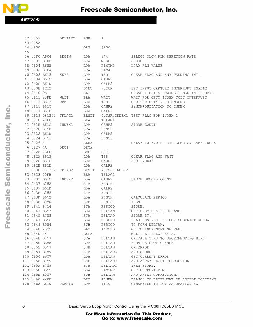
The listing (see MC68HC05B6 Servo Loop Motor Control Example) shows the assembly source code for speed measurement and the PD control of PLMA, which drives the power H-bridge in one direction. The opposite direction of rotation is obtained by complementing bits 0 and 1 of port A and driving the opposite lower leg of the H-bridge with PLMB. Eight-bit arithmetic was used exclusively in this example for space and clarity. Although this approach is functional, 16-bit routines for multiply and divide, given in Reference 2, are
dƒ(t)dt t = kT ≅
1T [ƒ (kT) – ƒ (k – 1)T]
2 Basic Servo Loop Motor Control Using the MC68HC05B6 MCU
For More Information On This Product, Go to: www.freescale.com

AN1120/DGeneral Description
F
ree
sca
le S
em
ico
nd
uc
tor,
I
Freescale Semiconductor, Inc.n
c..
.
Fig
ure
2. B
lock
Dia
gra
m o
f S
ervo
Lo
op
Mo
tor
Co
ntr
ol
+
+ +
+
+ +
GN
D3
INPU
T B4
INPU
T A2
V CC
6 5.7
V
+
GN
D3
INPU
T A
INPU
T B 42
V CC
6
100 k 100 k 100 k 100 k
MC
3315
1
+ +
+
+ +
––
10 2
DC
MO
TOR
12
9
4
3
5
8
Q2
Q1
Q3
Q4
7
6
V CC
MPM
3004
100
Ω
100
Ω
100
Ω
100
Ω
7 5
7
DRI
VEO
UTP
UT A
DRI
VEO
UTP
UT B
DRI
VEO
UTP
UT A
DRI
VEO
UTP
UT B
5
2
240
ΩV C
C
270
Ω
OUT
PUT
MRD
750
1M
LED
71
3R
L
411018 6 15 24 25 26 27 28 29 30 31 32 33 34 35 36 37 38 39 42 43 44 45 46 47 48 49
10 K
16 17 19 9 11 22 8 7 40 20 21 51 52 50 1 2 23 3 4 5 13 14 12
RESE
T
NCNC PA7
PA6
PA5
PA4
PA3
PA2
PA1
PA0
PB7
PB6
PB5
PB4
PB3
PB2
PB1
PB0
PC7
PC6
PC5
PC4
PC3
PC2
PC1
PC0
OS C
1
IRQ
OSC
2
PD4
PD3
TCAP
1
V RH
V RL
V PP1
PLM
A
PLM
B
SCLK
TDO
RDI
TCM
P2
TCM
P1
TCAP
2
PD7
PD6
PD5
PD1
PD0
PC2
MC68HC05B4/B6 MCU
V DD
V SS
+
Basic Servo Loop Motor Control Using the MC68HC05B6 MCU 3
For More Information On This Product, Go to: www.freescale.com

AN1120/D
F
ree
sca
le S
em
ico
nd
uc
tor,
I
Freescale Semiconductor, Inc.n
c..
.
better for finer control. Routines to set initial values, control direction of rotation, and check for motor stall are also necessary, although they are not shown in this application note.
Figure 3 shows the response of the system to various changes in load. The data was captured in an emulator trace buffer (Motorola CDS8 Jewelbox) and plotted using a data base program. Beginning from a no-load condition at 4 s, loading (an uncalibrated friction brake) was ramped to cause approximately a 50-percent duty cycle. Starting at 10 s, the load was then increased again until the system was at the limit of compliance — i.e., at full power and still maintaining the desired speed. Next, at 14 s, approximately half the load was rapidly (0.1 s) removed. The gain of the proportional term was 2, and the derivative constant was 1. In systems where a low-pass filter would be beneficial or the steady state error is potentially large, an integral term could be added for full PID control.
Figure 3. Step Response of PLM Motor Control
References
1. Kuo, Benjamin C., Automatic Control Systems, New Jersey: Prentice-Hall, 1987.
2. M6805UM/AD2, M6805 HMOS/M146805 CMOS Family User’s Manual, New Jersey: Prentice-Hall, 1983.
3. MC68HC05B6/D, MC68HC05B6 Data Sheet, Motorola, 1988.
4. M68HC05AG/AD, M68HC05 Applications Guide, Motorola, 1989.
100
90
80
70
60
50
40
30
20
100 2 4 6 8 10 12 14 16 18
PLM
DUT
Y C
YCLE
(PER
CEN
T)
TIME (s)
4 Basic Servo Loop Motor Control Using the MC68HC05B6 MCU
For More Information On This Product, Go to: www.freescale.com

AN1120/DMC68HC05B6 Servo Loop Motor Control Example
F
ree
sca
le S
em
ico
nd
uc
tor,
I
Freescale Semiconductor, Inc.n
c..
.
MC68HC05B6 Servo Loop Motor Control Example
1 **************************************************************************** 2 * MC68HC05B6 SERVO LOOP MOTOR CONTROL EXAMPLE * 3 * This program performs a closed loop servo speed control using PLMA for * 4 * output. Speed is measured optically with a slotted disk. The optically * 5 * detected index mark, controls TCAP2 which allows calculation of the * 6 * period of revolution for the loop input. * 7 **************************************************************************** 8 9 0000 org $0 10 cycles off 11 0000 12 0000 PADR RMB 1 13 0001 PBDR RMB 1 14 0002 PCDR RMB 1 15 0003 PDIDR RMB 1 16 0004 PADDR RMB 1 17 0005 PBDDR RMB 1 18 0006 PCDDR RMB 1 19 20 000A ORG $0A 21 22 000A PLMA RMB 1 23 000B PLMB RMB 1 24 000C MISC RMB 1 25 26 0012 ORG $12 27 28 0012 TCR RMB 1 29 0013 TSR RMB 1 30 0014 CAHR1 RMB 1 31 0015 CALR1 RMB 1 32 0016 COHR1 RMB 1 33 0017 COLR1 RMB 1 34 0018 CNTHR RMB 1 35 0019 CNTLR RMB 1 36 001A ACNTHR RMB 1 37 001B ACNTLR RMB 1 38 001C CAHR2 RMB 1 39 001D CALR2 RMB 1 40 41 0050 ORG $50 42 43 0050 BCNTH RMB 1 44 0051 BCNTL RMB 1 45 0052 ECNTH RMB 1 46 0053 ECNTL RMB 1 47 0054 PERIOD RMB 1 48 0055 PLMTMP RMB 1 MUST BE INITIALIZED WITH STARTING VALUE 49 0056 DESPRD RMB 1 MUST BE INITIALIZED WITH DESIRED PERIOD COUNT 50 0057 DELTAN RMB 1 51 0058 DELTAO RMB 1
Basic Servo Loop Motor Control Using the MC68HC05B6 MCU 5
For More Information On This Product, Go to: www.freescale.com
AN1120/D
F
ree
sca
le S
em
ico
nd
uc
tor,
I
Freescale Semiconductor, Inc.n
c..
.
52 0059 DELTADC RMB 1 53 005A 54 0F00 ORG $F00 55 56 00F0 A604 BEGIN LDA #$4 SELECT SLOW PLM REPETION RATE 57 0F02 B70C STA MISC SPEED 58 0F04 B655 LDA PLMTMP LOAD PLM VALUE 59 0F06 B70A STA PLMA 60 0F08 B613 KEYS LDA TSR CLEAR FLAG AND ANY PENDING INT. 61 0F0A B61C LDA CAHR2 62 0F0C B61D LDA CALR2 63 0F0E 1E12 BSET 7,TCR SET INPUT CAPTURE INTERRUPT ENABLE 64 0F10 9A CLI CLEAR I BIT ALLOWING TIMER INTERRUPTS 65 0F11 20FE WAIT BRA WAIT WAIT FOR OPTO INDEX TCIC INTERRUPT 66 0F13 B613 RPM LDA TSR CLR TSR BITY 4 TO ENSURE 67 0F15 B61C LDA CAHR2 SYNCHRONIZATION TO INDEX 68 0F17 B61D LDA CALR2 69 0F19 081302 TFLAG1 BRSET 4,TSR,INDEX1 TEST FLAG FOR INDEX 1 70 0F1C 20FB BRA TFLAG1 71 0F1E B61C INDEX1 LDA CAHR2 STORE COUNT 72 0F20 B750 STA BCNTH 73 0F22 B61D LDA CALR2 74 0F24 B751 STA BCNTL 75 0F26 4F CLRA DELAY TO AVOID RETRIGGER ON SAME INDEX 76 0F27 4A DEC1 DECA 77 0F28 26FD BNE DEC1 78 0F2A B613 LDA TSR CLEAR FLAG AND WAIT 79 0F2C B61C LDA CAHR2 FOR INDEX2 80 0F2E B61D LDA CALR2 81 0F30 081302 TFLAG2 BRSET 4,TSR,INDEX2 82 0F33 20FB BRA TFLAG2 83 0F35 B61C INDEX2 LDA CAHR2 STORE SECOND COUNT 84 0F37 B752 STA ECNTH 85 0F39 B61D LDA CALR2 86 0F3B B753 STA ECNTL 87 0F3D B652 LDA ECNTH CALCULATE PERIOD 88 0F3F B050 SUB BCNTH THEN 89 0F41 B754 STA PERIOD STORE. 90 0F43 B657 LDA DELTAN GET PREVIOUS ERROR AND 91 0F45 B758 STA DELTAO STORE IT. 92 0F47 B656 LDA DESPRD LOAD DESIRED PERIOD, SUBTRACT ACTUAL 93 0F49 B054 SUB PERIOD TO FORM DELTAN. 94 0F4B 2529 BLO INCSPD GO TO INCREMENTING PLM 95 0F4D 48 LSLA MULTIPLY ERROR BY 2. 96 0F4E B757 STA DELTAN OR FALL THRU TO DECREMENTING HERE. 97 0F50 B658 LDA DELTAO FORM RATE OF CHANGE 98 0F52 B057 SUB DELTAN OR ERROR 99 0F54 B759 STA DELTADC AND STORE.100 0F56 B657 LDA DELTAN GET CURRENT ERROR101 0F58 B059 SUB DELTADC AND APPLY DE/DT CORRECTION102 0F5A B759 STA DELTADC THEN STORE.103 0F5C B655 LDA PLMTMP GET CURRENT PLM104 0F5E B057 SUB DELTAN AND APPLY CORRECTION.105 0560 2208 BHI ADJDN BRANCH TO DECREMENT IF RESULT POSITIVE106 0F62 A610 PLMMIN LDA #$10 OTHERWISE IN LOW SATURATION SO
6 Basic Servo Loop Motor Control Using the MC68HC05B6 MCU
For More Information On This Product, Go to: www.freescale.com

AN1120/DMC68HC05B6 Servo Loop Motor Control Example
F
ree
sca
le S
em
ico
nd
uc
tor,
I
Freescale Semiconductor, Inc.n
c..
.
107 0F64 B70A STA PLMA KEEP PLM AT MINIMUM.108 0F66 B755 STA PLMTMP109 0F68 2023 BRA DONE110 0F6A A110 ADJDN CMP #$10 SEE IF PLM AT MINIMUM111 0F6C 2202 BHI DECSPD112 0F6E 20F2 BRA PLMMIN113 0F70 B70A DECSPD STA PLMA DECREMENT PLMA114 0F72 B755 STA PLMTMP UPDATE PLMA TEMPORARY LOCATION115 0F74 2107 BRA DONE116 0F76 48 INCSPD LSLA MULTIPLY ERROR BY 2117 0F77 B757 STA DELTAN INCREMENT WITH SATURATION118 0F79 B658 LDA DELTAO FORM RATE OF CHANGE119 0F7B B057 SUB DELTAN OF ERROR.120 0F7D BB57 ADD DELTAN NOW ADD IT TO CURRENT DELTA121 0F7F B759 STA DELTADC TO FORM RATE OF CHANGE COMPENSATED ERROR.122 0F81 B655 LDA PLMTMP GET CURRENT PLM123 0F83 B059 SUB DELTADC AND APPLY CORRECTION.124 0F85 2502 BL0 ADJUP125 0F87 2004 BRA DONE IN SATURATION OR CORRECTION EQUALS 0126 0F89 B70A ADJUP STA PLMA127 0F8B B755 STA PLMTMP128 0F8D 80 DONE RTI RETURN TO WAIT129130131 1FF0 ORG $1FF0 SET VECTORS132 1FF0 0F00 FDB BEGIN R133 1FF2 0F00 FDB BEGIN SCI134 1FF4 0F00 FDB BEGIN TOV135 1FF6 0F00 FDB BEGIN TOC136 1FF8 0F13 FDB RPM TIC137 1FFA 0F00 FDB BEGIN IRQ138 1FFC 0F00 FDB BEGIN SWI139 1FFE 0F00 FDB BEGIN RES140 2000 END
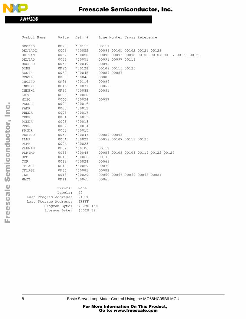
Symbol Table:
Symbol Name Value Def. # Line Number Cross Reference
ACNTHR 001A *00036ACNTLR 001B *00037ADJDN 0F6A *00110 00105ADJUP 0F89 *00126 00124BCNTH 0050 *00043 00072 00088BCNTL 0051 *00044 00074BEGIN 0F00 *00056 00132 00133 00134 00135 00137 00138 00139CAHR1 0014 *00030CAHR2 001C *0038 00061 00067 00071 00079 00083CALR1 0015 *00031CALR2 001D *00039 00062 00068 00073 00080 00085CNTHR 0018 *00034CNTLR 0019 *00035COHR1 0016 *00032COLR1 0017 *00033DEC1 0F27 *00076 00077
Basic Servo Loop Motor Control Using the MC68HC05B6 MCU 7
For More Information On This Product, Go to: www.freescale.com
AN1120/D
F
ree
sca
le S
em
ico
nd
uc
tor,
I
Freescale Semiconductor, Inc.n
c..
.
Symbol Name Value Def. # Line Number Cross Reference
DECSPD 0F70 *00113 00111DELTADC 0059 *00052 00099 00101 00102 00121 00123DELTAN 0057 *00050 00090 00096 00098 00100 00104 00117 00119 00120DELTAO 0058 *00051 00091 00097 00118DESPRD 0056 *00049 00092DONE 0F8D *00128 00109 00115 00125ECNTH 0052 *00045 00084 00087ECNTL 0053 *00046 00086INCSPD 0F76 *00116 00094INDEX1 0F1E *00071 00069INDEX2 0F35 *00083 00081KEYS 0F08 *00060MISC 000C *00024 00057PADDR 0004 *00016PADR 0000 *00012PBDDR 0005 *00017PBDR 0001 *00013PCDDR 0006 *00018PCDR 0002 *00014PDIDR 0003 *00015PERIOD 0054 *00047 00089 00093PLMA 000A *00022 00059 00107 00113 00126PLMB 000B *00023PLMMIN 0F62 *00106 00112PLMTMP 0055 *00048 00058 00103 00108 00114 00122 00127RPM 0F13 *00066 00136TCR 0012 *00028 00063TFLAG1 0F19 *00069 00070TFLAG2 0F30 *00081 00082TSR 0013 *00029 00060 00066 00069 00078 00081WAIT 0F11 *00065 00065
Errors: NoneLabels: 47
Last Program Address: $1FFFLast Storage Address: $FFFF
Program Byte: $009E 158Storage Byte: $0020 32
8 Basic Servo Loop Motor Control Using the MC68HC05B6 MCU
For More Information On This Product, Go to: www.freescale.com
AN1120/DMC68HC05B6 Servo Loop Motor Control Example
F
ree
sca
le S
em
ico
nd
uc
tor,
I
Freescale Semiconductor, Inc.n
c..
.
Basic Servo Loop Motor Control Using the MC68HC05B6 MCU 9
For More Information On This Product, Go to: www.freescale.com
AN1120/D
F
ree
sca
le S
em
ico
nd
uc
tor,
I
Freescale Semiconductor, Inc.n
c..
.
10 Basic Servo Loop Motor Control Using the MC68HC05B6 MCU
For More Information On This Product, Go to: www.freescale.com

AN1120/DMC68HC05B6 Servo Loop Motor Control Example
F
ree
sca
le S
em
ico
nd
uc
tor,
I
Freescale Semiconductor, Inc.n
c..
.
Basic Servo Loop Motor Control Using the MC68HC05B6 MCU 11
For More Information On This Product, Go to: www.freescale.com
F
ree
sca
le S
em
ico
nd
uc
tor,
I
Freescale Semiconductor, Inc.n
c..
.
AN1120/D For More Information On This Product,
Go to: www.freescale.com