an0025: peripheral reflex system (prs) · 1. peripheral reflex system 1.1 introduction the...
TRANSCRIPT
AN0025: Peripheral Reflex System (PRS)
This application note describes the Peripheral Reflex System(PRS) features and how these can be used to improve the sys-tem’s energy performance and reduce MCU workload and laten-cy.Some examples are presented and described in detail.
For simplicity, EFM32 Wonder Gecko, Gecko, Giant Gecko, Leopard Gecko, TinyGecko, Zero Gecko, and Happy Gecko are a part of the EFM32 Gecko Series 0.
EZR32 Wonder Gecko, Leopard Gecko, and Happy Gecko are a part of the EZR32Wireless MCU Series 0.
EFM32 Pearl Gecko and Jade Gecko (and future devices) are a part of the EFM32Gecko Series 1.
EFR32 Blue Gecko, Flex Gecko, and Mighty Gecko are a part of the EFR32 WirelessGecko Series 1.
KEY POINTS
• This document discusses PRS producersand consumers.
• Asynchronous mode PRS for EM2/3operation.
• The enhanced PRS supports configurablelogic.
• This application note includes:• This PDF document• Source files
• Example C-code• Multiple IDE projects
Timer
ADC
DMA
PRS Ch
PRS Ch
silabs.com | Smart. Connected. Energy-friendly. Rev. 1.08
1. Peripheral Reflex System
1.1 Introduction
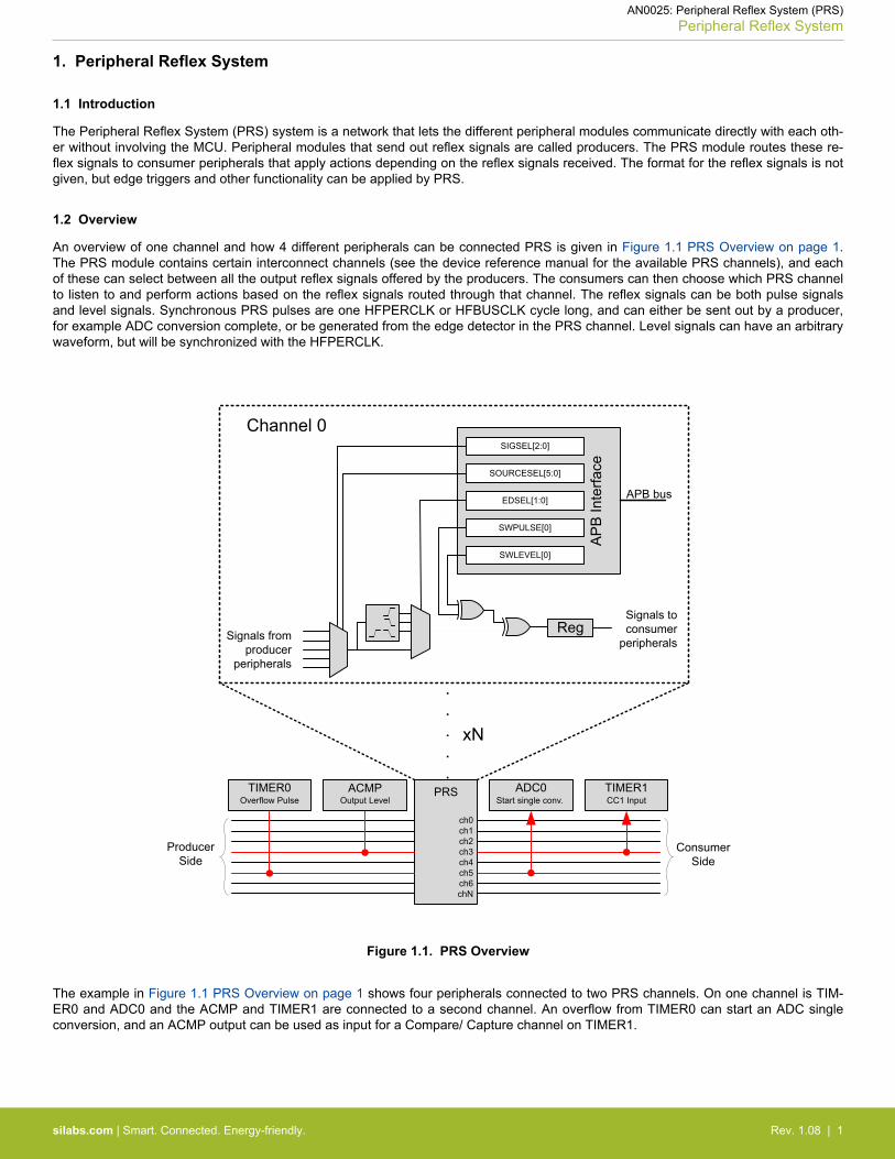
The Peripheral Reflex System (PRS) system is a network that lets the different peripheral modules communicate directly with each oth-er without involving the MCU. Peripheral modules that send out reflex signals are called producers. The PRS module routes these re-flex signals to consumer peripherals that apply actions depending on the reflex signals received. The format for the reflex signals is notgiven, but edge triggers and other functionality can be applied by PRS.
1.2 Overview
An overview of one channel and how 4 different peripherals can be connected PRS is given in Figure 1.1 PRS Overview on page 1.The PRS module contains certain interconnect channels (see the device reference manual for the available PRS channels), and eachof these can select between all the output reflex signals offered by the producers. The consumers can then choose which PRS channelto listen to and perform actions based on the reflex signals routed through that channel. The reflex signals can be both pulse signalsand level signals. Synchronous PRS pulses are one HFPERCLK or HFBUSCLK cycle long, and can either be sent out by a producer,for example ADC conversion complete, or be generated from the edge detector in the PRS channel. Level signals can have an arbitrarywaveform, but will be synchronized with the HFPERCLK.
AP
B In
terfa
ce
Reg
SIGSEL[2:0]
EDSEL[1:0] APB bus
Signals from producer
peripherals
Signals to consumer
peripherals
SWPULSE[0]
SWLEVEL[0]
SOURCESEL[5:0]
PRSTIMER0 ADC0
ch0ch1ch2ch3ch4ch5ch6chN
Start single conv.
Producer Side
Overflow Pulse
Consumer Side
TIMER1CC1 Input
ACMPOutput Level
xN
Channel 0
.
.
.
.
.
Figure 1.1. PRS Overview
The example in Figure 1.1 PRS Overview on page 1 shows four peripherals connected to two PRS channels. On one channel is TIM-ER0 and ADC0 and the ACMP and TIMER1 are connected to a second channel. An overflow from TIMER0 can start an ADC singleconversion, and an ACMP output can be used as input for a Compare/ Capture channel on TIMER1.
AN0025: Peripheral Reflex System (PRS)Peripheral Reflex System
silabs.com | Smart. Connected. Energy-friendly. Rev. 1.08 | 1
2. General Operation
2.1 Asynchronous Mode
Reflex channels can operate in two modes: synchronous or asynchronous. In synchronous mode, reflex signals are clocked on theHFPERCLK or HFBUSCLK (available in EFM32 Gecko Series 1 and EFR32 Wireless Gecko Series 1 devices) and can be used by anyreflex consumer. However, this will not work in Energy Mode 2 (EM2) or Energy Mode 3 (EM3), since the HFPERCLK or HFBUSCLKwill be turned off.
Asynchronous reflex channels are not clocked on HFPERCLK or HFBUSCLK and can be used even in Energy Mode 2 (EM2) or Ener-gy Mode 3 (EM3). However, the asynchronous mode can only be used by a subset of the reflex consumers marked with Async Supportin Table 2.3 Reflex Consumers on page 6. Peripherals that can produce asynchronous reflexes are marked with Async Support inTable 2.2 Reflex Producers on page 4.
To use these reflex signals asynchronously, set the ASYNC bitfield in the PRS_CHx_CTRL register for the PRS channel selecting thereflex signal (see 4.6 Asynchronous GPIO PRS Triggered PCNT in EM2 and 5.4 Asynchronous GPIO PRS Triggered PCNT in EM3).
Note:1. Asynchronous mode is not available in the EFM32 Gecko (EFM32G) device.2. If a reflex channel with ASYNC set is used in a consumer not supporting asynchronous reflexes, the behavior is undefined.
2.2 Channel Functions
Different functions can be applied to a reflex signal within the PRS module. Each channel includes an edge detector to enable genera-tion of pulse signals from level signals.
Edge detection can be applied to a PRS signal using the EDSEL bitfield in the PRS_CHx_CTRL register. When edge detection is ena-bled, changes in the PRS input will result in a pulse on the PRS channel.
In EFM32 Gecko Series 1 and EFR32 Wireless Gecko Series 1 devices:
• Signals on the PRS input also have to be at least one HFBUSCLK period wide in order to be detected properly. This applies to allcases when asynchronous mode is not used in the PRS.
• There are two options for communication between peripherals on different prescaled clocks, for example between peripherals onHFBUSCLK and HFPERCLK:• For level signals, no action is needed, but software must make sure that the level signals are held long enough for the destination
domain to detect them.• For pulse signals, edge detection and stretch (EDSEL and STRETCH bitfields in the PRS_CHx_CTRL register) should be ena-
bled. When edge detection and stretch are enabled on a PRS source, the output on the PRS channel is held long enough for thedestination domain to detect the pulse. This also works if there are multiple destination domains running at different frequencies.
The PRS channels can also be manually triggered by writing to the PRS_SWPULSE or PRS_SWLEVEL registers (see 4.4 SoftwareGenerated PRS Pulse Triggers DAC Conversion).
PRS_SWLEVEL is a programmable level for each channel and holds the value it is programmed to. The PRS_SWPULSE register willcause the PRS channel to output a one-HFPERCLK or one-HFBUSCLK cycle high pulse if the corresponding channel bit is set to 1.
The SWLEVEL and SWPULSE signals are then XOR'ed with the selected input from the producers to form the output signal sent to theconsumers listening to the channel. For example, when SWLEVEL is set, if a producer produces a signal of 1, this will cause a channeloutput of 0. This is illustrated in Figure 1.1 PRS Overview on page 1.
The emlib functions• void PRS_SourceSignalSet(unsigned int ch, uint32_t source, uint32_t signal, PRS_Edge_TypeDef edge)
• void RS_SourceAsyncSignalSet(unsigned int ch, uint32_t source, uint32_t signal)
can be used to easily configure the PRS channels.
By specifying the PRS channel, producing peripheral, signal from the peripheral, and edge for pulse generation (synchronous mode),the function configures the PRS accordingly.
Note: The edge detector controlled by the EDSEL bitfield in the PRS_CHx_CTRL register should only be used when working with syn-chronous reflexes, that is, the ASYNC bitfield in the PRS_CHx_CTRL register is cleared.
AN0025: Peripheral Reflex System (PRS)General Operation
silabs.com | Smart. Connected. Energy-friendly. Rev. 1.08 | 2

2.3 Route PRS Channel to GPIO Pin
It is possible to route a PRS channel to a GPIO pin for debugging or use it as an enable signal.
Table 2.1. Route PRS Channel to GPIO pin
EFM32 Gecko Series 0 and EZR32 Series 0 EFM32 Gecko Series 1 and EFR32 Wireless GeckoSeries 1
Availability Only PRS channel 0 to 3 can route to GPIO pin All PRS channels can route to GPIO pin
Register PRS_ROUTE register for enable and location • PRS_ROUTE register for enable• PRS_ROUTELOCx registers for location
Note: This feature is not available in the EFM32 Gecko (EFM32G) device.
AN0025: Peripheral Reflex System (PRS)General Operation
silabs.com | Smart. Connected. Energy-friendly. Rev. 1.08 | 3
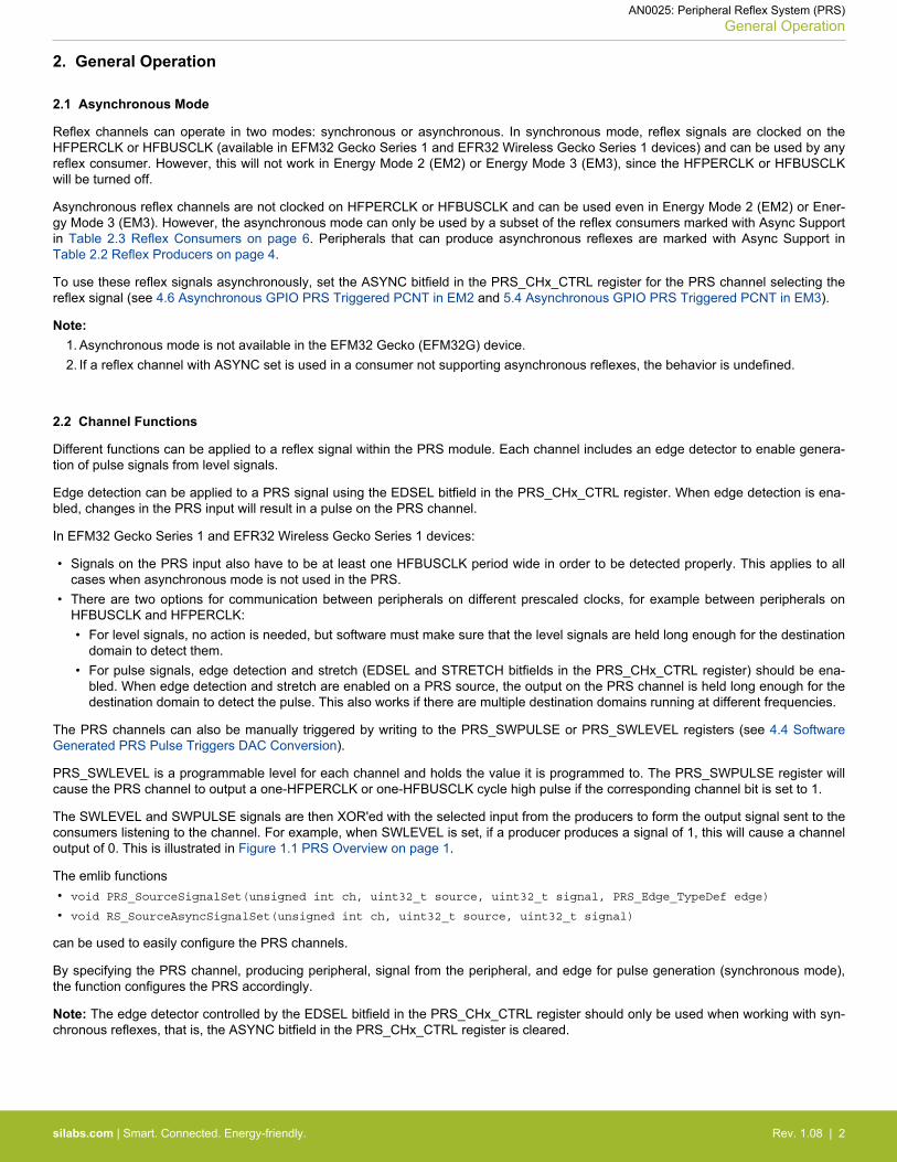
2.4 Producers
Each PRS channel can choose between signals from several producers, which is configured in the SOURCESEL bitfield in thePRS_CHx_CTRL register. Each producer outputs a signal which can be selected by setting the SIGSEL bitfield in the PRS_CHx_CTRLregister. Setting the SOURCESEL bitfield to 0 (off) leads to a constant zero output from the input mux. An overview of the availableproducers is given in the table below.
Note: Not all modules and reflex outputs are available on a given device. Refer to the device reference manual and data sheet fordetails.
Table 2.2. Reflex Producers
Module Reflex Output Output Format Async Support
ACMP Comparator Output Level Yes
ADC Single Conversion Done Pulse Yes1
Scan Conversion Done Pulse Yes1
DAC Channel 0 Conversion Done Pulse —
Channel 1 Conversion Done Pulse —
GPIO Pin 0 to Pin 15 Input Level Yes
RTC Overflow Pulse Yes
Compare Match 0 Pulse Yes
Compare Match 1 Pulse Yes
TIMER Underflow Pulse —
Overflow Pulse —
Compare/Capture Channel Out-put
Level —
UART TX Complete Pulse —
RX Data Received Pulse —
USART TX Complete Pulse —
RX Data Received Pulse —
IrDA Decoder Output Level —
RTS Output Level —
TX Output Level —
CS Output Level —
VCMP Comparator Output Level Yes
LETIMER CH0 Output Level Yes
CH1 Output Level Yes
LESENSE SCANRES Register Level Yes
Decoder Output Level/Pulse Yes
BURTC Overflow Pulse Yes
Compare Match 0 Pulse Yes
AN0025: Peripheral Reflex System (PRS)General Operation
silabs.com | Smart. Connected. Energy-friendly. Rev. 1.08 | 4
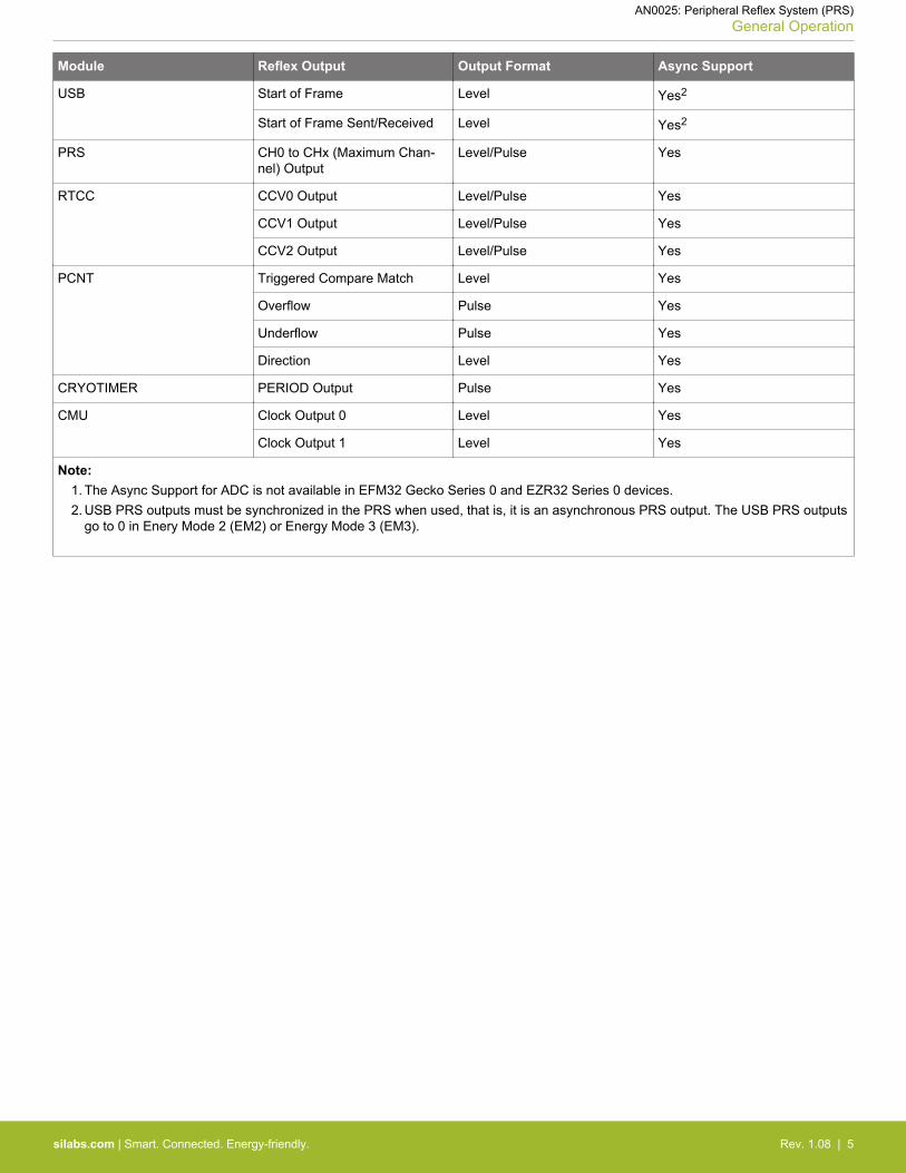
Module Reflex Output Output Format Async Support
USB Start of Frame Level Yes2
Start of Frame Sent/Received Level Yes2
PRS CH0 to CHx (Maximum Chan-nel) Output
Level/Pulse Yes
RTCC CCV0 Output Level/Pulse Yes
CCV1 Output Level/Pulse Yes
CCV2 Output Level/Pulse Yes
PCNT Triggered Compare Match Level Yes
Overflow Pulse Yes
Underflow Pulse Yes
Direction Level Yes
CRYOTIMER PERIOD Output Pulse Yes
CMU Clock Output 0 Level Yes
Clock Output 1 Level Yes
Note:1. The Async Support for ADC is not available in EFM32 Gecko Series 0 and EZR32 Series 0 devices.2. USB PRS outputs must be synchronized in the PRS when used, that is, it is an asynchronous PRS output. The USB PRS outputs
go to 0 in Enery Mode 2 (EM2) or Energy Mode 3 (EM3).
AN0025: Peripheral Reflex System (PRS)General Operation
silabs.com | Smart. Connected. Energy-friendly. Rev. 1.08 | 5
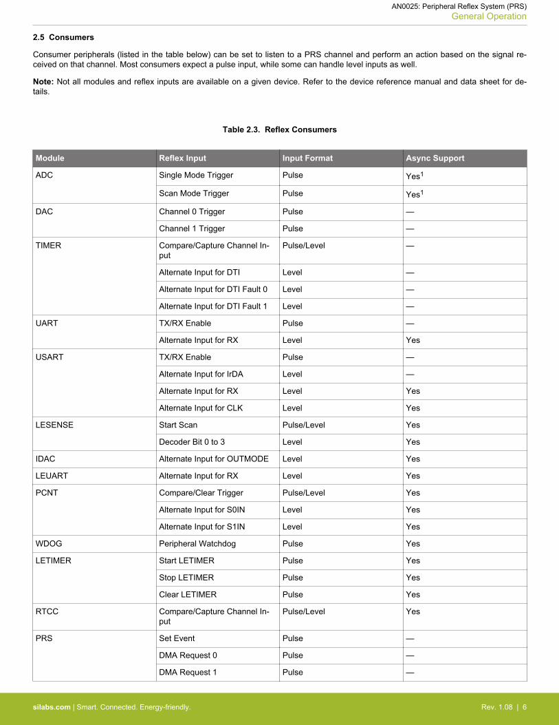
2.5 Consumers
Consumer peripherals (listed in the table below) can be set to listen to a PRS channel and perform an action based on the signal re-ceived on that channel. Most consumers expect a pulse input, while some can handle level inputs as well.
Note: Not all modules and reflex inputs are available on a given device. Refer to the device reference manual and data sheet for de-tails.
Table 2.3. Reflex Consumers
Module Reflex Input Input Format Async Support
ADC Single Mode Trigger Pulse Yes1
Scan Mode Trigger Pulse Yes1
DAC Channel 0 Trigger Pulse —
Channel 1 Trigger Pulse —
TIMER Compare/Capture Channel In-put
Pulse/Level —
Alternate Input for DTI Level —
Alternate Input for DTI Fault 0 Level —
Alternate Input for DTI Fault 1 Level —
UART TX/RX Enable Pulse —
Alternate Input for RX Level Yes
USART TX/RX Enable Pulse —
Alternate Input for IrDA Level —
Alternate Input for RX Level Yes
Alternate Input for CLK Level Yes
LESENSE Start Scan Pulse/Level Yes
Decoder Bit 0 to 3 Level Yes
IDAC Alternate Input for OUTMODE Level Yes
LEUART Alternate Input for RX Level Yes
PCNT Compare/Clear Trigger Pulse/Level Yes
Alternate Input for S0IN Level Yes
Alternate Input for S1IN Level Yes
WDOG Peripheral Watchdog Pulse Yes
LETIMER Start LETIMER Pulse Yes
Stop LETIMER Pulse Yes
Clear LETIMER Pulse Yes
RTCC Compare/Capture Channel In-put
Pulse/Level Yes
PRS Set Event Pulse —
DMA Request 0 Pulse —
DMA Request 1 Pulse —
AN0025: Peripheral Reflex System (PRS)General Operation
silabs.com | Smart. Connected. Energy-friendly. Rev. 1.08 | 6

Module Reflex Input Input Format Async Support
CMU Alternate Input for CalibrationUp-Counter
Level —
Alternate Input for CalibrationDown-Counter
Level —
Note:1. The Async Support for ADC is not available in EFM32 Gecko Series 0 and EZR32 Series 0 devices.
AN0025: Peripheral Reflex System (PRS)General Operation
silabs.com | Smart. Connected. Energy-friendly. Rev. 1.08 | 7
3. Advanced Features
These advanced features are not available in EFM32 Gecko Series 0 and EZR32 Series 0 devices.
3.1 Configurable PRS Logic
Each PRS channel has three logic functions that can be used by themselves or in combination. The selected PRS source can beAND'ed with the next PRS channel output, OR'ed with the previous PRS channel output, and inverted. The order of the functions isimportant. If OR and AND are enabled at the same time, AND is applied first, and then OR.
In addition to the logic functions that can combine a PRS channel with one of its neighbors, a PRS channel can also select any otherPRS channel as the input. This can allow relatively complex logic functions to be created (see 5.6 Configurable PRS Logic).
3.2 Event on PRS
The PRS can be used to send events to the MCU. This is very useful in combination with the Wait For Event (WFE) instruction. A singlePRS channel can be selected for this using the SEVONPRSSEL bitfield in the PRS_CTRL register, and the feature is enabled by set-ting the SEVONPRS bitfield in the same register (see 5.5 Event on PRS).
3.3 DMA Request on PRS
Up to two independent DMA requests (PRSREQ0 and PRSREQ1) can be generated by the PRS.
The PRS signals triggering the DMA requests are selected with the SOURCESEL (= 0x1 for PRS) and SIGNAL (= 0x0 for PRSREQ0 or= 0x1 for PRSREQ1) bitfields in the LDMA_CHx_REQSEL register.
The PRS channels for DMA requests are configured in the PRS_DMAREQ0 and PRS_DMAREQ1 registers. See AN1029: Linked Di-rect Memory Access Controller (LDMA) for more information. Application notes can be found on the Silicon Labs website at www.si-labs.com/32bit-appnotes or in Simplicity Studio (http://www.silabs.com/simplicity).
AN0025: Peripheral Reflex System (PRS)Advanced Features
silabs.com | Smart. Connected. Energy-friendly. Rev. 1.08 | 8

4. Software Examples for EFM32 Gecko Series 0
The software examples below are run on the EFM32 Gecko (project prs_example_gecko or STKXXX_prs_example), Tiny Gecko(project prs_example_tg or STK3300_prs_example), and Giant Gecko Starter Kits (project prs_example_gg or STK3700_prs_example), with common source file main_prs_example.c.
The example is selected by the menu displayed on the segment LCD, push button PB0 is used to browse the menu, and push buttonPB1 is used to execute the selected menu item. Press push button PB0 to exit if the selected menu item is running.
AN0025: Peripheral Reflex System (PRS)Software Examples for EFM32 Gecko Series 0
silabs.com | Smart. Connected. Energy-friendly. Rev. 1.08 | 9
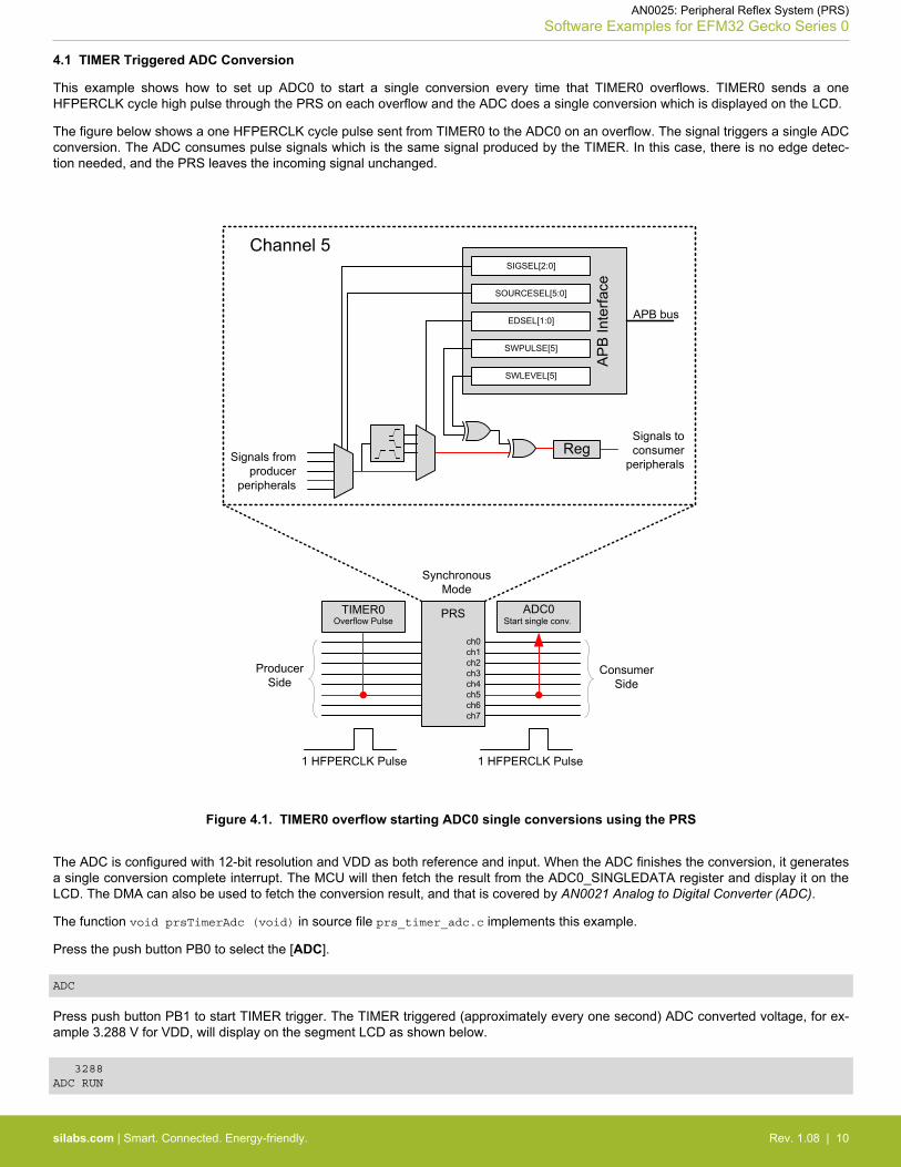
4.1 TIMER Triggered ADC Conversion
This example shows how to set up ADC0 to start a single conversion every time that TIMER0 overflows. TIMER0 sends a oneHFPERCLK cycle high pulse through the PRS on each overflow and the ADC does a single conversion which is displayed on the LCD.
The figure below shows a one HFPERCLK cycle pulse sent from TIMER0 to the ADC0 on an overflow. The signal triggers a single ADCconversion. The ADC consumes pulse signals which is the same signal produced by the TIMER. In this case, there is no edge detec-tion needed, and the PRS leaves the incoming signal unchanged.
TIMER0 ADC0
ch0ch1ch2ch3ch4ch5ch6ch7
Start single conv.
Producer Side
Overflow Pulse
Consumer Side
1 HFPERCLK Pulse
PRS
ch0ch1ch2ch3ch4ch5ch6ch7
AP
B In
terfa
ce
SIGSEL[2:0]
EDSEL[1:0] APB bus
Signals from producer
peripherals
Signals to consumer
peripherals
SWPULSE[5]
SWLEVEL[5]
SOURCESEL[5:0]
Channel 5
Reg
1 HFPERCLK Pulse
Synchronous Mode
Figure 4.1. TIMER0 overflow starting ADC0 single conversions using the PRS
The ADC is configured with 12-bit resolution and VDD as both reference and input. When the ADC finishes the conversion, it generatesa single conversion complete interrupt. The MCU will then fetch the result from the ADC0_SINGLEDATA register and display it on theLCD. The DMA can also be used to fetch the conversion result, and that is covered by AN0021 Analog to Digital Converter (ADC).
The function void prsTimerAdc (void) in source file prs_timer_adc.c implements this example.
Press the push button PB0 to select the [ADC].
ADC
Press push button PB1 to start TIMER trigger. The TIMER triggered (approximately every one second) ADC converted voltage, for ex-ample 3.288 V for VDD, will display on the segment LCD as shown below.
3288 ADC RUN
AN0025: Peripheral Reflex System (PRS)Software Examples for EFM32 Gecko Series 0
silabs.com | Smart. Connected. Energy-friendly. Rev. 1.08 | 10
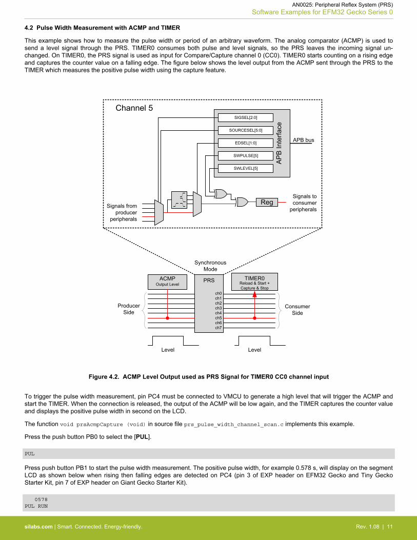
4.2 Pulse Width Measurement with ACMP and TIMER
This example shows how to measure the pulse width or period of an arbitrary waveform. The analog comparator (ACMP) is used tosend a level signal through the PRS. TIMER0 consumes both pulse and level signals, so the PRS leaves the incoming signal un-changed. On TIMER0, the PRS signal is used as input for Compare/Capture channel 0 (CC0). TIMER0 starts counting on a rising edgeand captures the counter value on a falling edge. The figure below shows the level output from the ACMP sent through the PRS to theTIMER which measures the positive pulse width using the capture feature.
ACMP TIMER0
ch0ch1ch2ch3ch4ch5ch6ch7
Producer Side
Output Level
Consumer Side
AP
B In
terfa
ce
SIGSEL[2:0]
EDSEL[1:0] APB bus
Signals from producer
peripherals
Signals to consumer
peripherals
SWPULSE[5]
SWLEVEL[5]
SOURCESEL[5:0]
Channel 5
Level Level
Reg
PRS
ch0ch1ch2ch3ch4ch5ch6ch7
Reload & Start + Capture & Stop
Synchronous Mode
Figure 4.2. ACMP Level Output used as PRS Signal for TIMER0 CC0 channel input
To trigger the pulse width measurement, pin PC4 must be connected to VMCU to generate a high level that will trigger the ACMP andstart the TIMER. When the connection is released, the output of the ACMP will be low again, and the TIMER captures the counter valueand displays the positive pulse width in second on the LCD.
The function void prsAcmpCapture (void) in source file prs_pulse_width_channel_scan.c implements this example.
Press the push button PB0 to select the [PUL].
PUL
Press push button PB1 to start the pulse width measurement. The positive pulse width, for example 0.578 s, will display on the segmentLCD as shown below when rising then falling edges are detected on PC4 (pin 3 of EXP header on EFM32 Gecko and Tiny GeckoStarter Kit, pin 7 of EXP header on Giant Gecko Starter Kit).
0578 PUL RUN
AN0025: Peripheral Reflex System (PRS)Software Examples for EFM32 Gecko Series 0
silabs.com | Smart. Connected. Energy-friendly. Rev. 1.08 | 11
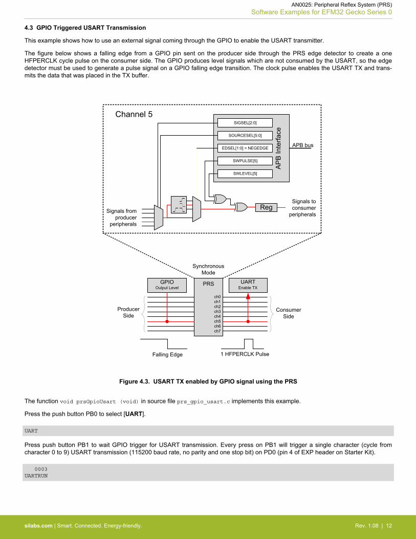
4.3 GPIO Triggered USART Transmission
This example shows how to use an external signal coming through the GPIO to enable the USART transmitter.
The figure below shows a falling edge from a GPIO pin sent on the producer side through the PRS edge detector to create a oneHFPERCLK cycle pulse on the consumer side. The GPIO produces level signals which are not consumed by the USART, so the edgedetector must be used to generate a pulse signal on a GPIO falling edge transition. The clock pulse enables the USART TX and trans-mits the data that was placed in the TX buffer.
GPIO UART
ch0ch1ch2ch3ch4ch5ch6ch7
Enable TX
Producer Side
Output Level
Consumer SideNegative
Edge Detector
AP
B In
terfa
ce
SIGSEL[2:0]
EDSEL[1:0] = NEGEDGE APB bus
Signals from producer
peripherals
Signals to consumer
peripherals
SWPULSE[5]
SWLEVEL[5]
SOURCESEL[5:0]
Channel 5
Falling Edge
Reg
PRS
ch0ch1ch2ch3ch4ch5ch6ch7
1 HFPERCLK Pulse
Synchronous Mode
Figure 4.3. USART TX enabled by GPIO signal using the PRS
The function void prsGpioUsart (void) in source file prs_gpio_usart.c implements this example.
Press the push button PB0 to select [UART].
UART
Press push button PB1 to wait GPIO trigger for USART transmission. Every press on PB1 will trigger a single character (cycle fromcharacter 0 to 9) USART transmission (115200 baud rate, no parity and one stop bit) on PD0 (pin 4 of EXP header on Starter Kit).
0003 UARTRUN
AN0025: Peripheral Reflex System (PRS)Software Examples for EFM32 Gecko Series 0
silabs.com | Smart. Connected. Energy-friendly. Rev. 1.08 | 12
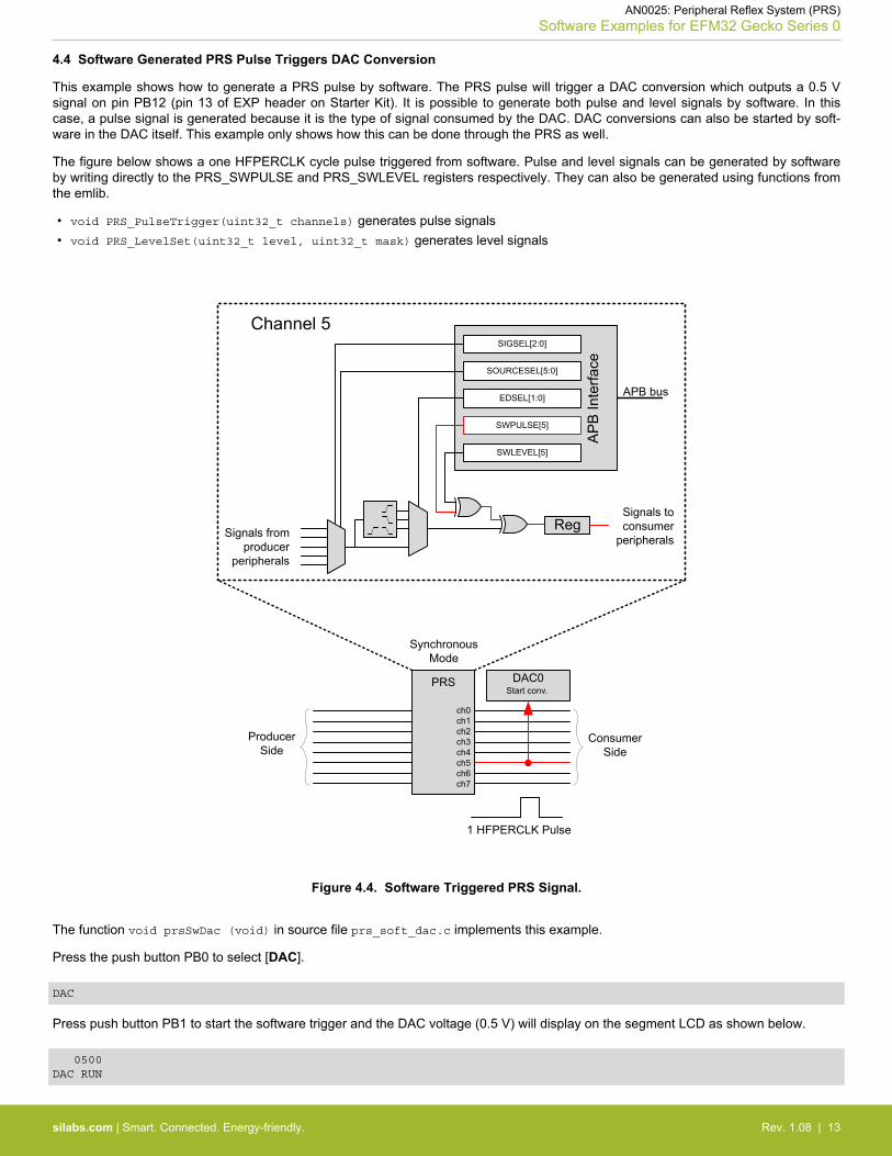
4.4 Software Generated PRS Pulse Triggers DAC Conversion
This example shows how to generate a PRS pulse by software. The PRS pulse will trigger a DAC conversion which outputs a 0.5 Vsignal on pin PB12 (pin 13 of EXP header on Starter Kit). It is possible to generate both pulse and level signals by software. In thiscase, a pulse signal is generated because it is the type of signal consumed by the DAC. DAC conversions can also be started by soft-ware in the DAC itself. This example only shows how this can be done through the PRS as well.
The figure below shows a one HFPERCLK cycle pulse triggered from software. Pulse and level signals can be generated by softwareby writing directly to the PRS_SWPULSE and PRS_SWLEVEL registers respectively. They can also be generated using functions fromthe emlib.
• void PRS_PulseTrigger(uint32_t channels) generates pulse signals• void PRS_LevelSet(uint32_t level, uint32_t mask) generates level signals
AP
B In
terfa
ce
SIGSEL[2:0]
EDSEL[1:0] APB bus
Signals from producer
peripherals
Signals to consumer
peripherals
SWPULSE[5]
SWLEVEL[5]
SOURCESEL[5:0]
Channel 5
PRS DAC0
ch0ch1ch2ch3ch4ch5ch6ch7
Start conv.
Producer Side
Consumer Side
Reg
1 HFPERCLK Pulse
Synchronous Mode
Figure 4.4. Software Triggered PRS Signal.
The function void prsSwDac (void) in source file prs_soft_dac.c implements this example.
Press the push button PB0 to select [DAC].
DAC
Press push button PB1 to start the software trigger and the DAC voltage (0.5 V) will display on the segment LCD as shown below.
0500 DAC RUN
AN0025: Peripheral Reflex System (PRS)Software Examples for EFM32 Gecko Series 0
silabs.com | Smart. Connected. Energy-friendly. Rev. 1.08 | 13

4.5 Monitoring of PRS Signals
The PRS channels can be monitored using peripherals that consume PRS signals. One example is using a TIMER to make a capturewhen there is activity on the PRS channel it is connected to.
The Compare/Capture channel 0 (CC0) on TIMER0 is used to capture a falling edge. When a capture is triggered, the user knows thatthere was activity on the selected PRS channel.
This example will wait on Energy Mode 1 (EM1) for activity in the PRS channel (TIMER0 capture interrupt). When such activity occurs,it writes the PRS trigger count on the LCD. To generate activity on this line, the user must connect PC4 (pin 3 of EXP header on EFM32Gecko and Tiny Gecko Starter Kit, pin 7 of EXP header on Giant Gecko Starter Kit) to VMCU to generate a rising edge transition on thePRS channel using the analog comparator (ACMP).
This example is useful for EFM32 Gecko (EFM32G) devices that cannot route a PRS channel to a GPIO pin for monitoring or debug-ging.
The function void prsMonitor (void) in source file prs_pulse_width_channel_scan.c implements this example.
Press the push button PB0 to select [MON].
MON
Press push button PB1 to start the monitor process and the PRS trigger count will display on the segment LCD as shown below.
0003 MON RUN
AN0025: Peripheral Reflex System (PRS)Software Examples for EFM32 Gecko Series 0
silabs.com | Smart. Connected. Energy-friendly. Rev. 1.08 | 14
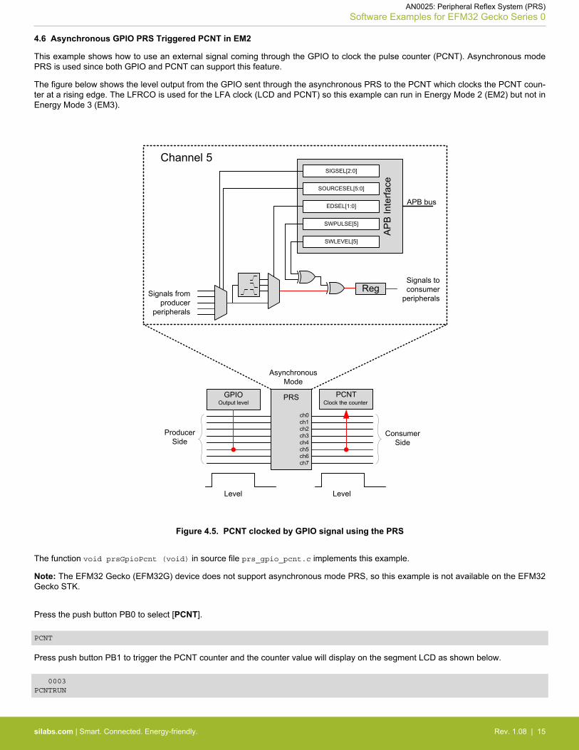
4.6 Asynchronous GPIO PRS Triggered PCNT in EM2
This example shows how to use an external signal coming through the GPIO to clock the pulse counter (PCNT). Asynchronous modePRS is used since both GPIO and PCNT can support this feature.
The figure below shows the level output from the GPIO sent through the asynchronous PRS to the PCNT which clocks the PCNT coun-ter at a rising edge. The LFRCO is used for the LFA clock (LCD and PCNT) so this example can run in Energy Mode 2 (EM2) but not inEnergy Mode 3 (EM3).
GPIO PCNT
ch0ch1ch2ch3ch4ch5ch6ch7
Clock the counter
Producer Side
Output level
Consumer Side
PRS
ch0ch1ch2ch3ch4ch5ch6ch7
AP
B In
terfa
ce
SIGSEL[2:0]
EDSEL[1:0] APB bus
Signals from producer
peripherals
Signals to consumer
peripherals
SWPULSE[5]
SWLEVEL[5]
SOURCESEL[5:0]
Channel 5
Reg
Level Level
Asynchronous Mode
Figure 4.5. PCNT clocked by GPIO signal using the PRS
The function void prsGpioPcnt (void) in source file prs_gpio_pcnt.c implements this example.
Note: The EFM32 Gecko (EFM32G) device does not support asynchronous mode PRS, so this example is not available on the EFM32Gecko STK.
Press the push button PB0 to select [PCNT].
PCNT
Press push button PB1 to trigger the PCNT counter and the counter value will display on the segment LCD as shown below.
0003 PCNTRUN
AN0025: Peripheral Reflex System (PRS)Software Examples for EFM32 Gecko Series 0
silabs.com | Smart. Connected. Energy-friendly. Rev. 1.08 | 15
5. Software Examples for EFM32 Gecko Series 1
The software examples below are run on the EFM32 Pearl Gecko Starter Kit (SLSTK3401A_EFM32PG). These examples are groupedinto one project (prs_example_pg or SLSTK3401A_prs_example) with source file main_prs_example.c.
The example is selected by the menu displayed on the Memory LCD, push button BTN1 is used to browse the menu, and push buttonBTN0 is used to execute the selected menu item. Press push button BTN1 to exit if the selected menu item is running.
5.1 TIMER Triggered ADC Conversion
Refer to 4.1 TIMER Triggered ADC Conversion for a detailed description of this example. The function void prsTimerAdc (void) insource file prs_timer_adc.c implements this example.
Press the push button BTN1 to select [Timer Triggered ADC Conversion].
Example 1Timer TriggeredADC Conversion
Press BTN1 to nextmenuPress BTN0 to start
Press push button BTN0 to start the TIMER trigger. The TIMER-triggered (approximately every one second) ADC-converted voltage willdisplay on the Memory LCD as shown below.
Example 1Timer TriggeredADC Conversion
Trigger interval ~1sAVDD: 3.2887V
Press BTN1 to exit
5.2 Pulse Width Measurement with ACMP and TIMER
Refer to 4.2 Pulse Width Measurement with ACMP and TIMER for a detailed description of this example. The function void prsAcmpCapture (void) in source file prs_pulse_width_channel_scan.c implements this example.
Press the push button BTN1 to select [Pulse Width Measurement on PA4 with ACMP and TIMER].
Example 2Pulse WidthMeasurement on PA4with ACMP and TIMER
Press BTN1 to nextmenuPress BTN0 to start
Press push button BTN0 to start the pulse width measurement. The pulse width will display on the Memory LCD as shown below whenrising then falling edges are detected on PA4 (pin 7 of EXP header on Starter Kit).
Example 2Pulse WidthMeasurement on PA4with ACMP and TIMER
Positive pulse width:0.2399s
Press BTN1 to exit
AN0025: Peripheral Reflex System (PRS)Software Examples for EFM32 Gecko Series 1
silabs.com | Smart. Connected. Energy-friendly. Rev. 1.08 | 16
5.3 GPIO Triggered USART Transmission
Refer to 4.3 GPIO Triggered USART Transmission for a detailed description of this example. The function void prsGpioUsart (void)in source file prs_gpio_usart.c implements this example.
Press the push button BTN1 to select [GPIO Triggered USART Transmission].
Example 3GPIO Triggered USARTTransmission
Press BTN1 to nextmenuPress BTN0 to start
Press push button BTN0 to start GPIO triggers for USART transmission. Every press on BTN0 will trigger a single character (cycle fromcharacter 0 to 9) USART transmission (115200 baud rate, no parity and one stop bit) on PC7 (pin 6 of EXP header on Starter Kit).
Example 3GPIO Triggered USARTTransmission
Press BTN0 to triggerUSART TX on PC7
Character: 1
Press BTN1 to exit
5.4 Asynchronous GPIO PRS Triggered PCNT in EM3
Refer to 4.6 Asynchronous GPIO PRS Triggered PCNT in EM2 for a detailed description of this example. The function void prsGpioPcnt (void) in source file prs_gpio_pcnt.c implements this example. The ULFRCO is used for the LFA clock (PCNT) so this examplecan run in Energy Mode 2 (EM2) and Energy Mode 3 (EM3).
Press the push button BTN1 to select [Asynchronous GPIO PRS Triggered PCNT in EM3].
Example 4Asynchronous GPIO PRSTriggered PCNT in EM3
Press BTN1 to nextmenuPress BTN0 to start
Press push button BTN0 to trigger the PCNT counter, and the counter value will display on the Memory LCD as shown below.
Example 4Asynchronous GPIO PRSTriggered PCNT in EM3
Press BTN0 to triggerPCNT
PCNT CNT: 00003
Press BTN1 to exit
AN0025: Peripheral Reflex System (PRS)Software Examples for EFM32 Gecko Series 1
silabs.com | Smart. Connected. Energy-friendly. Rev. 1.08 | 17
5.5 Event on PRS
This example demonstrates how to send event to the MCU through the PRS.
The TIMER0 is setup to trigger an event to the MCU periodically (approximately every one second), every time letting the MCU passthrough a Wait For Event (WFE) instruction in its program.
This can help in performance critical sections where timing is known, and the goal is to wait for an event, then execute some code, thenwait for an event, then execute some code and so on.
The function void prsTimerWfe (void) in source file prs_timer_wfe.c implements this example.
Press the push button BTN1 to select [Event on PRS - WFE in EM1].
Example 5Event on PRS - WFE inEM1
Press BTN1 to nextmenuPress BTN0 to start
Press push button BTN0 to start the TIMER trigger, and the wake up count will display on the Memory LCD as shown below.
Example 5Event on PRS - WFE inEM1
Periodic (~1s) PRSEvent from TIMER
PRS Wakeup: 0008
Press BTN1 to exit
5.6 Configurable PRS Logic
This example demonstrates how to use the configurable logic in PRS to reduce the current consumption in a thermistor application.
The target is to evaluate the ADC result (temperature) autonomously and only give the MCU an interrupt if the sample is outside orinside the given thresholds.
The functions void rtccSetup (void), void adcPrsLogic (void), void adcSetup (void), and void prsConfigLogic (void) insource file prs_rtcc_logic.c implement this example.
AN0025: Peripheral Reflex System (PRS)Software Examples for EFM32 Gecko Series 1
silabs.com | Smart. Connected. Energy-friendly. Rev. 1.08 | 18
5.6.1 Design Concept
Power gating is critical in this scenario, since the current consumption of the thermistor (~30 to 60 μA) becomes dominant in sleepmode (~2 μA) unless the MCU makes sure the thermistor is powered only when it is being sampled.
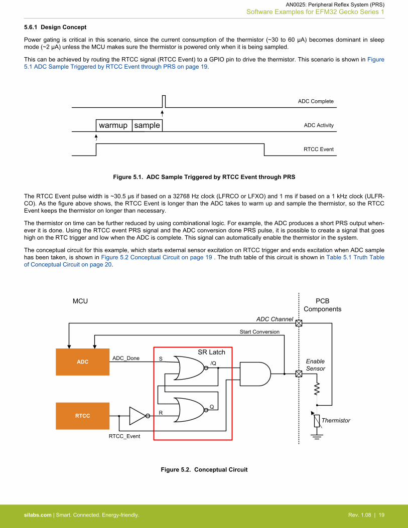
This can be achieved by routing the RTCC signal (RTCC Event) to a GPIO pin to drive the thermistor. This scenario is shown in Figure5.1 ADC Sample Triggered by RTCC Event through PRS on page 19.
RTCC Event
ADC Activity
ADC Complete
warmup sample
Figure 5.1. ADC Sample Triggered by RTCC Event through PRS
The RTCC Event pulse width is ~30.5 μs if based on a 32768 Hz clock (LFRCO or LFXO) and 1 ms if based on a 1 kHz clock (ULFR-CO). As the figure above shows, the RTCC Event is longer than the ADC takes to warm up and sample the thermistor, so the RTCCEvent keeps the thermistor on longer than necessary.
The thermistor on time can be further reduced by using combinational logic. For example, the ADC produces a short PRS output when-ever it is done. Using the RTCC event PRS signal and the ADC conversion done PRS pulse, it is possible to create a signal that goeshigh on the RTC trigger and low when the ADC is complete. This signal can automatically enable the thermistor in the system.
The conceptual circuit for this example, which starts external sensor excitation on RTCC trigger and ends excitation when ADC samplehas been taken, is shown in Figure 5.2 Conceptual Circuit on page 19 . The truth table of this circuit is shown in Table 5.1 Truth Tableof Conceptual Circuit on page 20.
MCU PCBComponents
RTCC
ADC EnableSensor
ADC Channel
ADC_Done
RTCC_Event
S
R
/Q
SR Latch
Start Conversion
Q
Thermistor
Figure 5.2. Conceptual Circuit
AN0025: Peripheral Reflex System (PRS)Software Examples for EFM32 Gecko Series 1
silabs.com | Smart. Connected. Energy-friendly. Rev. 1.08 | 19

Table 5.1. Truth Table of Conceptual Circuit
RTCC_Event SR Latch Input S
(ADC_Done)
SR Latch Input R
(/RTCC_Event)
SR Latch Output /Q Enable Sensor
(RTCC_Event & /Q)
0 0 1 1 0
1 0 0 1 1
1 1 0 0 0
1 0 0 0 0
Initially, the SR latch output /Q is high and Enable Sensor is low because the RTCC_Event output and the ADC_Done output are low.Whenever the RTCC_Event now goes high, the external sensor is enabled, and the ADC starts taking a sample. Once the ADC isdone, the ADC_Done signal goes high, setting the SR latch output /Q low, which forces the external sensor off. When the RTCC eventsignal goes low again, the SR latch is reset, making the system ready for the next event.
AN0025: Peripheral Reflex System (PRS)Software Examples for EFM32 Gecko Series 1
silabs.com | Smart. Connected. Energy-friendly. Rev. 1.08 | 20
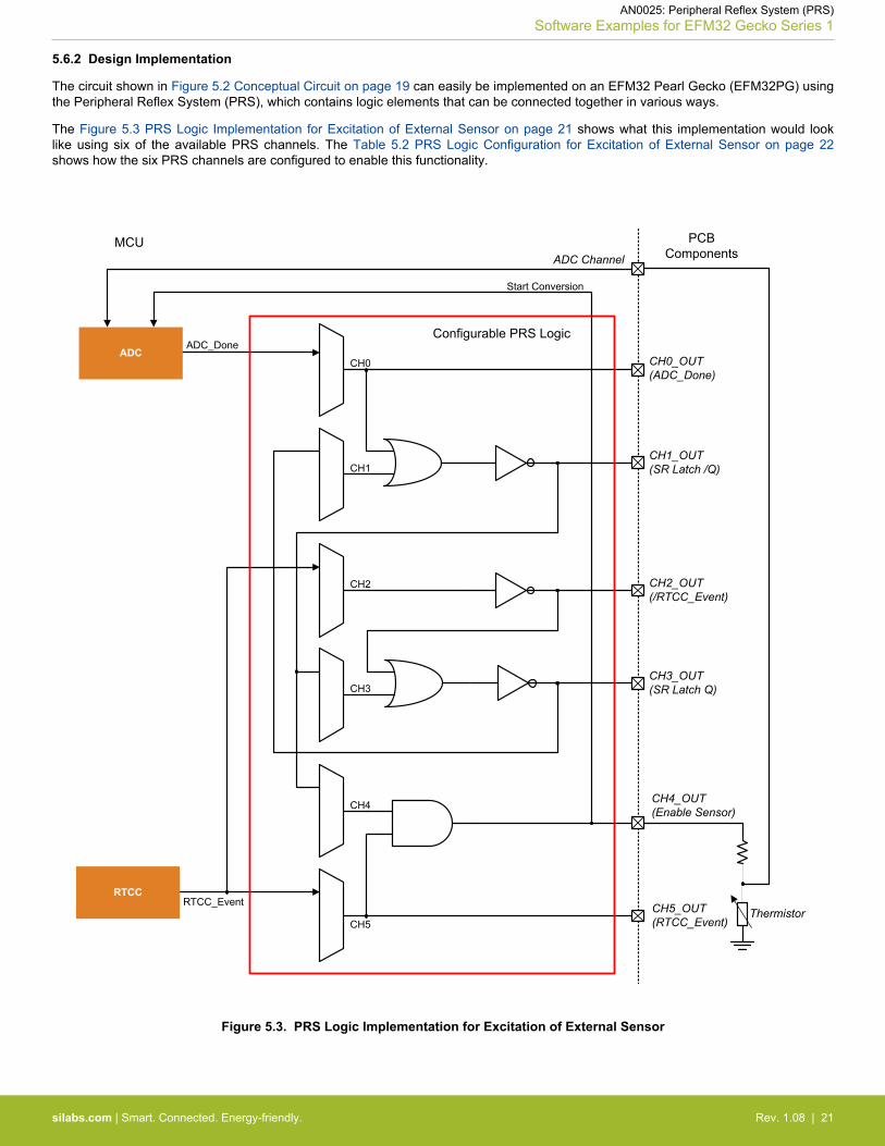
5.6.2 Design Implementation
The circuit shown in Figure 5.2 Conceptual Circuit on page 19 can easily be implemented on an EFM32 Pearl Gecko (EFM32PG) usingthe Peripheral Reflex System (PRS), which contains logic elements that can be connected together in various ways.
The Figure 5.3 PRS Logic Implementation for Excitation of External Sensor on page 21 shows what this implementation would looklike using six of the available PRS channels. The Table 5.2 PRS Logic Configuration for Excitation of External Sensor on page 22shows how the six PRS channels are configured to enable this functionality.
RTCC
ADCADC_Done
RTCC_Event
CH0
CH1
CH2
CH3
CH4
CH5
Configurable PRS Logic
PCBComponents
CH4_OUT(Enable Sensor)
ADC Channel
Start Conversion
MCU
CH0_OUT(ADC_Done)
CH1_OUT(SR Latch /Q)
CH2_OUT(/RTCC_Event)
CH3_OUT(SR Latch Q)
CH5_OUT(RTCC_Event)
Thermistor
Figure 5.3. PRS Logic Implementation for Excitation of External Sensor
AN0025: Peripheral Reflex System (PRS)Software Examples for EFM32 Gecko Series 1
silabs.com | Smart. Connected. Energy-friendly. Rev. 1.08 | 21
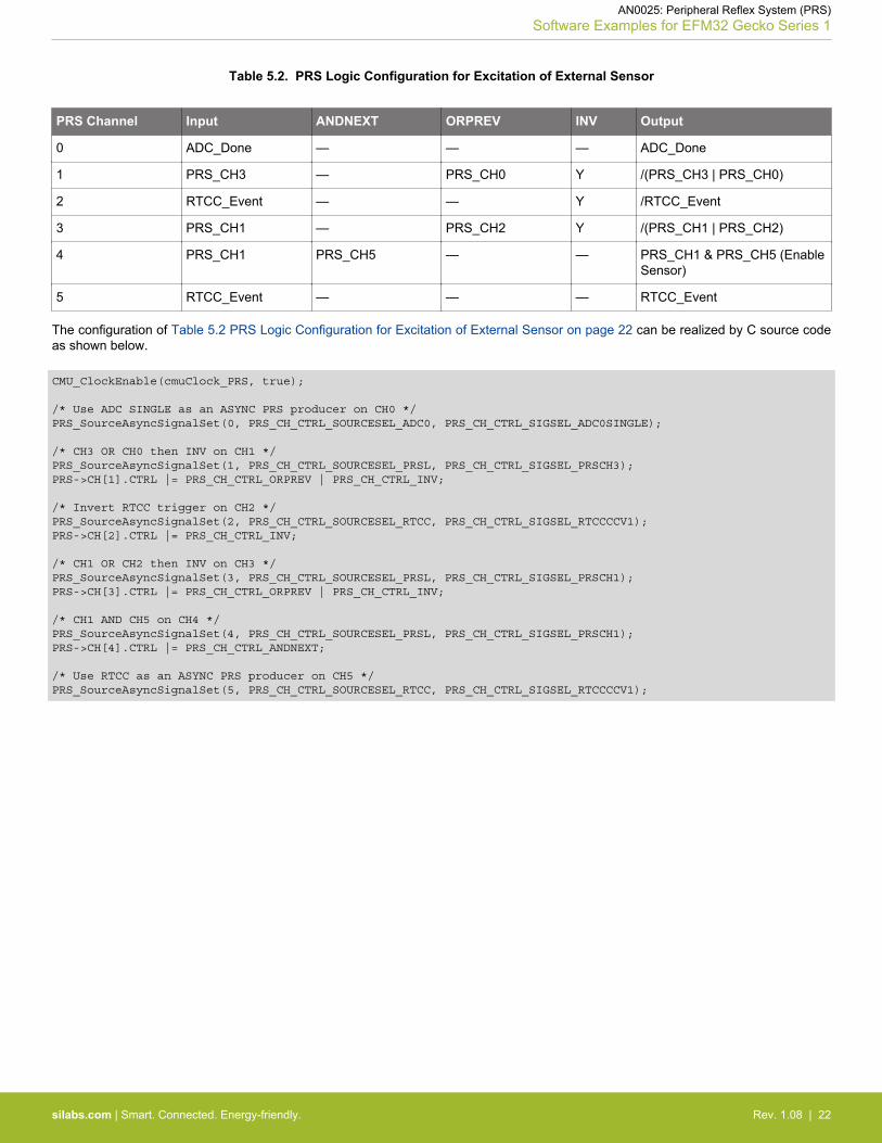
Table 5.2. PRS Logic Configuration for Excitation of External Sensor
PRS Channel Input ANDNEXT ORPREV INV Output
0 ADC_Done — — — ADC_Done
1 PRS_CH3 — PRS_CH0 Y /(PRS_CH3 | PRS_CH0)
2 RTCC_Event — — Y /RTCC_Event
3 PRS_CH1 — PRS_CH2 Y /(PRS_CH1 | PRS_CH2)
4 PRS_CH1 PRS_CH5 — — PRS_CH1 & PRS_CH5 (EnableSensor)
5 RTCC_Event — — — RTCC_Event
The configuration of Table 5.2 PRS Logic Configuration for Excitation of External Sensor on page 22 can be realized by C source codeas shown below.
CMU_ClockEnable(cmuClock_PRS, true);
/* Use ADC SINGLE as an ASYNC PRS producer on CH0 */PRS_SourceAsyncSignalSet(0, PRS_CH_CTRL_SOURCESEL_ADC0, PRS_CH_CTRL_SIGSEL_ADC0SINGLE);
/* CH3 OR CH0 then INV on CH1 */PRS_SourceAsyncSignalSet(1, PRS_CH_CTRL_SOURCESEL_PRSL, PRS_CH_CTRL_SIGSEL_PRSCH3);PRS->CH[1].CTRL |= PRS_CH_CTRL_ORPREV | PRS_CH_CTRL_INV; /* Invert RTCC trigger on CH2 */PRS_SourceAsyncSignalSet(2, PRS_CH_CTRL_SOURCESEL_RTCC, PRS_CH_CTRL_SIGSEL_RTCCCCV1);PRS->CH[2].CTRL |= PRS_CH_CTRL_INV; /* CH1 OR CH2 then INV on CH3 */PRS_SourceAsyncSignalSet(3, PRS_CH_CTRL_SOURCESEL_PRSL, PRS_CH_CTRL_SIGSEL_PRSCH1);PRS->CH[3].CTRL |= PRS_CH_CTRL_ORPREV | PRS_CH_CTRL_INV;
/* CH1 AND CH5 on CH4 */PRS_SourceAsyncSignalSet(4, PRS_CH_CTRL_SOURCESEL_PRSL, PRS_CH_CTRL_SIGSEL_PRSCH1);PRS->CH[4].CTRL |= PRS_CH_CTRL_ANDNEXT;
/* Use RTCC as an ASYNC PRS producer on CH5 */PRS_SourceAsyncSignalSet(5, PRS_CH_CTRL_SOURCESEL_RTCC, PRS_CH_CTRL_SIGSEL_RTCCCCV1);
AN0025: Peripheral Reflex System (PRS)Software Examples for EFM32 Gecko Series 1
silabs.com | Smart. Connected. Energy-friendly. Rev. 1.08 | 22
5.6.3 Test Results
This example uses the configurable PRS logic to trigger the ADC single conversion at 100 Hz. The EFM32 Pearl Gecko stays in EnergyMode 3 (EM3) and wakes up with the ADC SINGLECMP interrupt.
The clock configurations for this example are listed below.
• Core clock — 16 MHz HFRCO• ADC conversion clock — 13 MHz AUXHFRCO in ASYNC mode• RTCC — Use 1 kHz ULFRCO as clock source for EM3 operation
The ADC configurations for this example are listed below.
• PRS enable — Trigger from PRS channel 4• Reference — AVDD• Input — PA0 (pin 12 of EXP header on EFM32PG Starter Kit)• FIFO overflow action — FIFO overwrites old data when full• ADC acquisition time — One ADC conversion clock cycle• ADC conversion resolution — 12 bit• ADC bias programming — Set GPBIASACC bitfield in the ADCn_BIASPROG register to LOWACC• ADC clock mode — ASYNC and use AUXHFRCO as clock source for EM3 operation• ADC interrupt — Single result compare matched (SINGLECMP)
The ADC compare thresholds below are used in this example.
• ADC ADGT — 3724 (~3V for AVDD = 3.3 V)• ADC ADLT — 620 (~0.5V for AVDD = 3.3 V)
The ADC compare matched interrupt will be triggered when PA0 input voltage is lower than the ADLT threshold or higher than theADGT threshold.
Two 100 kΩ resistors are used to emulate the thermistor potential divider, and the current consumption is about 16 μA (3.3 V/200000)when the Enable Sensor signal is high.
The PRS channel signal can route to a GPIO pin for debugging or to use it as an enable signal. Table 5.3 GPIO Pins Used for PRSChannels on page 23 shows which GPIO pins are used in this example for different PRS channels.
Except GPIO for PRS channel 4 (Sensor Enable), all PRS channel outputs are disabled by default to reduce the current consumption.Set the PRS_DEBUG_OUT define in prs_rtcc_logic.c to 1 to enable all PRS channel outputs.
Table 5.3. GPIO Pins Used for PRS Channels
PRS Channel Signal GPIO I/O Routing Location Pin on EFM32PG STK
0 ADC_Done PF2 2 Pin 9 of J102
1 SR Latch /Q PF3 2 Pin 11 of J102
2 /RTCC_Event PF4 (share with LED0) 2 Pin 13 of J102
3 SR Latch Q PF5 (share with LED1) 2 Pin 15 of J102
4 Enable Sensor PD10 1 • Pin 8 of J102• Pin 9 of EXP Header
5 RTCC_Event PD11 1 • Pin 10 of J102• Pin 11 of EXP Header
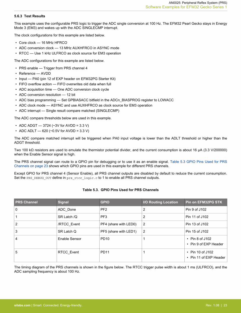
The timing diagram of the PRS channels is shown in the figure below. The RTCC trigger pulse width is about 1 ms (ULFRCO), and theADC sampling frequency is about 100 Hz.
AN0025: Peripheral Reflex System (PRS)Software Examples for EFM32 Gecko Series 1
silabs.com | Smart. Connected. Energy-friendly. Rev. 1.08 | 23
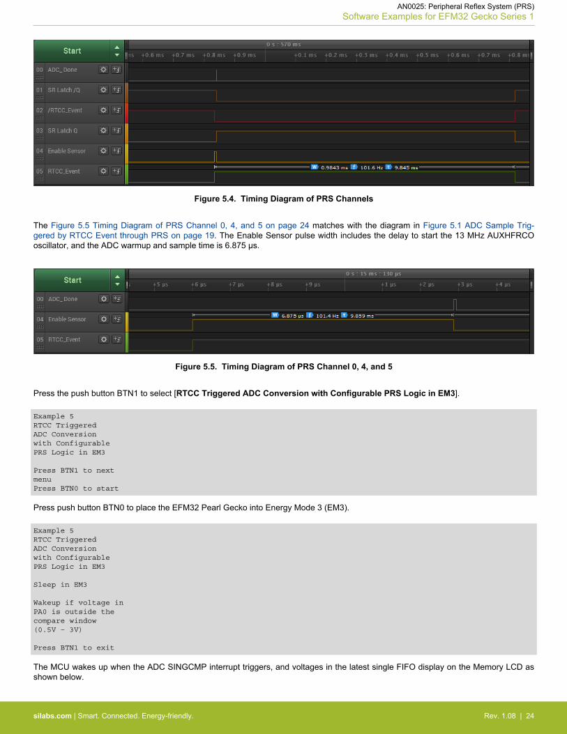
Figure 5.4. Timing Diagram of PRS Channels
The Figure 5.5 Timing Diagram of PRS Channel 0, 4, and 5 on page 24 matches with the diagram in Figure 5.1 ADC Sample Trig-gered by RTCC Event through PRS on page 19. The Enable Sensor pulse width includes the delay to start the 13 MHz AUXHFRCOoscillator, and the ADC warmup and sample time is 6.875 μs.
Figure 5.5. Timing Diagram of PRS Channel 0, 4, and 5
Press the push button BTN1 to select [RTCC Triggered ADC Conversion with Configurable PRS Logic in EM3].
Example 5RTCC TriggeredADC Conversionwith ConfigurablePRS Logic in EM3
Press BTN1 to nextmenuPress BTN0 to start
Press push button BTN0 to place the EFM32 Pearl Gecko into Energy Mode 3 (EM3).
Example 5RTCC TriggeredADC Conversionwith ConfigurablePRS Logic in EM3
Sleep in EM3
Wakeup if voltage inPA0 is outside thecompare window(0.5V – 3V)
Press BTN1 to exit
The MCU wakes up when the ADC SINGCMP interrupt triggers, and voltages in the latest single FIFO display on the Memory LCD asshown below.
AN0025: Peripheral Reflex System (PRS)Software Examples for EFM32 Gecko Series 1
silabs.com | Smart. Connected. Energy-friendly. Rev. 1.08 | 24
Example 5RTCC TriggeredADC Conversionwith ConfigurablePRS Logic in EM3
ADC Compare Interrupt
FIFO 0: 1.4212VFIFO 1: 1.4212VFIFO 2: 1.4212VFIFO 3: 0.0008V
Press BTN1 to exit
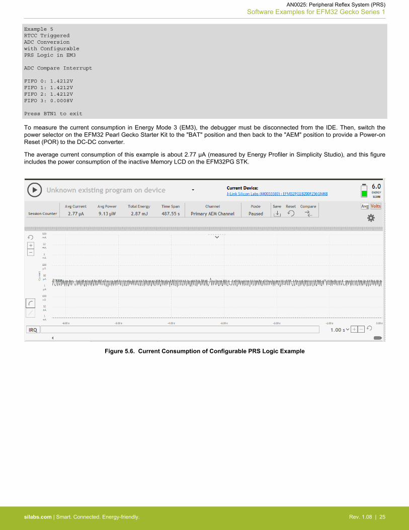
To measure the current consumption in Energy Mode 3 (EM3), the debugger must be disconnected from the IDE. Then, switch thepower selector on the EFM32 Pearl Gecko Starter Kit to the "BAT" position and then back to the "AEM" position to provide a Power-onReset (POR) to the DC-DC converter.
The average current consumption of this example is about 2.77 µA (measured by Energy Profiler in Simplicity Studio), and this figureincludes the power consumption of the inactive Memory LCD on the EFM32PG STK.
Figure 5.6. Current Consumption of Configurable PRS Logic Example
AN0025: Peripheral Reflex System (PRS)Software Examples for EFM32 Gecko Series 1
silabs.com | Smart. Connected. Energy-friendly. Rev. 1.08 | 25
6. Revision History
6.1 Revision 1.08
2016-11-18
Updated example code for EFM32 Gecko Series 0
Added example code for EFM32 Gecko Series 1
Updated document for EFM32 Gecko Series 1
6.2 Revision 1.07
2014-05-07
Updated example code to CMSIS 3.20.5
Changed to Silicon Labs license on code examples
Added project files for Simplicity IDE
Removed makefiles for Sourcery CodeBench Lite
6.3 Revision 1.06
2013-10-14
New cover layout
6.4 Revision 1.05
2013-05-08
Added software projects for ARM-GCC and Atollic TrueStudio.
6.5 Revision 1.04
2012-11-12
Adapted software projects to new kit-driver and bsp structure.
Added software support for Tiny and Giant Gecko STK.
6.6 Revision 1.03
2012-04-20
Adapted software projects to new peripheral library naming and CMSIS_V3.
6.7 Revision 1.02
2011-10-21
Updated IDE project paths with new kits directory.
6.8 Revision 1.01
2011-05-18
Updated projects to align with new bsp version.
6.9 Revision 1.00
2010-12-13
Initial revision.
AN0025: Peripheral Reflex System (PRS)Revision History
silabs.com | Smart. Connected. Energy-friendly. Rev. 1.08 | 26

http://www.silabs.com
Silicon Laboratories Inc.400 West Cesar ChavezAustin, TX 78701USA
Simplicity StudioOne-click access to MCU and wireless tools, documentation, software, source code libraries & more. Available for Windows, Mac and Linux!
IoT Portfoliowww.silabs.com/IoT
SW/HWwww.silabs.com/simplicity
Qualitywww.silabs.com/quality
Support and Communitycommunity.silabs.com
DisclaimerSilicon Labs intends to provide customers with the latest, accurate, and in-depth documentation of all peripherals and modules available for system and software implementers using or intending to use the Silicon Labs products. Characterization data, available modules and peripherals, memory sizes and memory addresses refer to each specific device, and "Typical" parameters provided can and do vary in different applications. Application examples described herein are for illustrative purposes only. Silicon Labs reserves the right to make changes without further notice and limitation to product information, specifications, and descriptions herein, and does not give warranties as to the accuracy or completeness of the included information. Silicon Labs shall have no liability for the consequences of use of the information supplied herein. This document does not imply or express copyright licenses granted hereunder to design or fabricate any integrated circuits. The products are not designed or authorized to be used within any Life Support System without the specific written consent of Silicon Labs. A "Life Support System" is any product or system intended to support or sustain life and/or health, which, if it fails, can be reasonably expected to result in significant personal injury or death. Silicon Labs products are not designed or authorized for military applications. Silicon Labs products shall under no circumstances be used in weapons of mass destruction including (but not limited to) nuclear, biological or chemical weapons, or missiles capable of delivering such weapons.
Trademark InformationSilicon Laboratories Inc.® , Silicon Laboratories®, Silicon Labs®, SiLabs® and the Silicon Labs logo®, Bluegiga®, Bluegiga Logo®, Clockbuilder®, CMEMS®, DSPLL®, EFM®, EFM32®, EFR, Ember®, Energy Micro, Energy Micro logo and combinations thereof, "the world’s most energy friendly microcontrollers", Ember®, EZLink®, EZRadio®, EZRadioPRO®, Gecko®, ISOmodem®, Precision32®, ProSLIC®, Simplicity Studio®, SiPHY®, Telegesis, the Telegesis Logo®, USBXpress® and others are trademarks or registered trademarks of Silicon Labs. ARM, CORTEX, Cortex-M3 and THUMB are trademarks or registered trademarks of ARM Holdings. Keil is a registered trademark of ARM Limited. All other products or brand names mentioned herein are trademarks of their respective holders.