an x-mode reflectometry study on the reflection point for
TRANSCRIPT

An X-mode reflectometry study on the reflection point for the density profile reconstruction
S. Heuraux, F. Clairet£, F. da Silva°
IJL Nancy-Université CNRS UMR 7198, BP 70239, F-54506 Vandoeuvre Cedex, France £Association Euratom-CEA_Cadarache 13108 St Paul-lez-Durance – France
°Associação EURATOM/IST-IPFN Instituto Superior Técnico, 1046-001 Lisboa, Portugal
I) Context:
The amplitude of the reflected signal rises as the frequency F reaches the first edge cut-off at F ~ Fce (electron cyclotron frequency) corresponding to a rapid change of the group delay occurring at the first cut-off frequency [1]. In the case of Tore Supra, below the first cut-off, the wave travels trough the plasma and the reflection occurs at the back wall while above the first cut-off the wave is reflected into the plasma (see fig.1). Before reaching the reflecting point part of the probing wave is reflected by the plasma and at the same time a jump in time of flight is seen. Since some uncertainty exists on the true position of the reflected point. An initialisation point has to be found in both information sources: the time of flight and the amplitude as a function of the probing frequency F. For a clean time of flight it is possible to use it, assuming that the jump of the time of flight is associated to an identified frequency F = Fce (electron cyclotron frequency) otherwise, if the time of flight is very noisy then an other method can be used, using usually the amplitude variation as a function of the frequency. However different thresholds are used to determine the position of the electron cyclotron frequency and to precise the framework of the density profile reconstruction, theoretical and numerical studies have been done on the amplitude variation when the probing frequency crosses the electron frequency.
figure 1: (left) Time of flight associated to a sweep frequency in Tore Supra plasma and
(right) amplitude of the reflected signal as a function of the probing frequency. However the definition of the initialisation point needs to be precise to define properly an initial position, using the knowledge of the magnetic field topology, assumed to be known precisely. This study explores also the precise position where F=Fce has well defined meaning and can be used to initialize the first position point of the density profile. Two 1D full-wave codes: (i) A Helmholtz code, assuming that the probing wave reaches an asymptotic state with a negligible frequency change and (ii) a wave equation solver having a very fast frequency sweep where the electromagnetic flux conservation law induces a modification of the amplitude of the probing wave. The role of collision on the positioning

of the first point has also been studied as well as the role of the density gradient length L. To conclude a criterion is proposed to define precisely when the probing frequency can be considered equal to the electron cyclotron frequency.
II) Modelling
Under the WKB approximation one can have an idea of the evolution of the probing wavenumber during its path in the magnetized plasma and determine if the wave can go through the plasma onto the lower branch of the X-mode for a given range of probing frequency. In a first case at low magnetic field intensity all the probing frequency sees a cut-off layer. The lower frequencies propagate until they reach the cut-off of the lower branch of the X-mode and then for F > Fce the cut-off of the upper branch of the X-mode. In a second case of high intensity of the magnetic field the wave propagates without seeing cut-off during their flight to the inner wall in the usual range of the probing frequency (50-75 GHz) until the electron cyclotron frequency. However by looking at the index when the frequency of the probing wave becomes of the order of the electron cyclotron frequency, a quasi-jump of the index can be observed with an index variation of the order of one. A reflection is induced according to classical optics laws, so the reflection of the probing wave begins for a frequency below the electron cyclotron frequency and changes continuously. Here is considered only the X-mode, which has no resonant absorption at the electron cyclotron frequency, so no particular damping can be observed in the vicinity of the electron cyclotron frequency as it is in the experiments [1]. An interesting point not mentioned is that the O-mode is damped at the electron cyclotron layer then in this case so the spurious effects induced by O-mode are reduced due to a misalignment of the receiver and can be neglected. From these facts it is possible to build a simple model able to provide a criterion to determine a relation between the amplitude of the reflected wave and the electron cyclotron frequency based on the index jump at F = Fce (see fig 3 left).
Figure 2: Evolution of the different cut-off positions and characteristic frequencies for two case low magnetic field intensity (left) and high magnetic field (right): fce electron cyclotron frequency (blue), fuh upper hybrid frequency (magenta), fpe plasma frequency (black), fc- lower branch cut-off frequency (green) of the X-mode and fc+ upper branch cut-off frequency (red). The reflection coefficient is equal r = (n1-n2)/(n1+n2) where n1 is the index of the incoming wave (vacuum n1~1) and n2 is the index of the X-mode (n1~2 at F = Fce – ε, ε small parameter). This mode gives just an evaluation of the reflection coefficient at the index jump. A full-wave analysis is needed to describe the reflection coefficient at all frequency [2]. Eq.(53) in [2] corresponds to a general expression of the reflection coefficient in one dimensional analysis, R= 1− e −
πkoro where ko is the vacuum wave number and ro is the
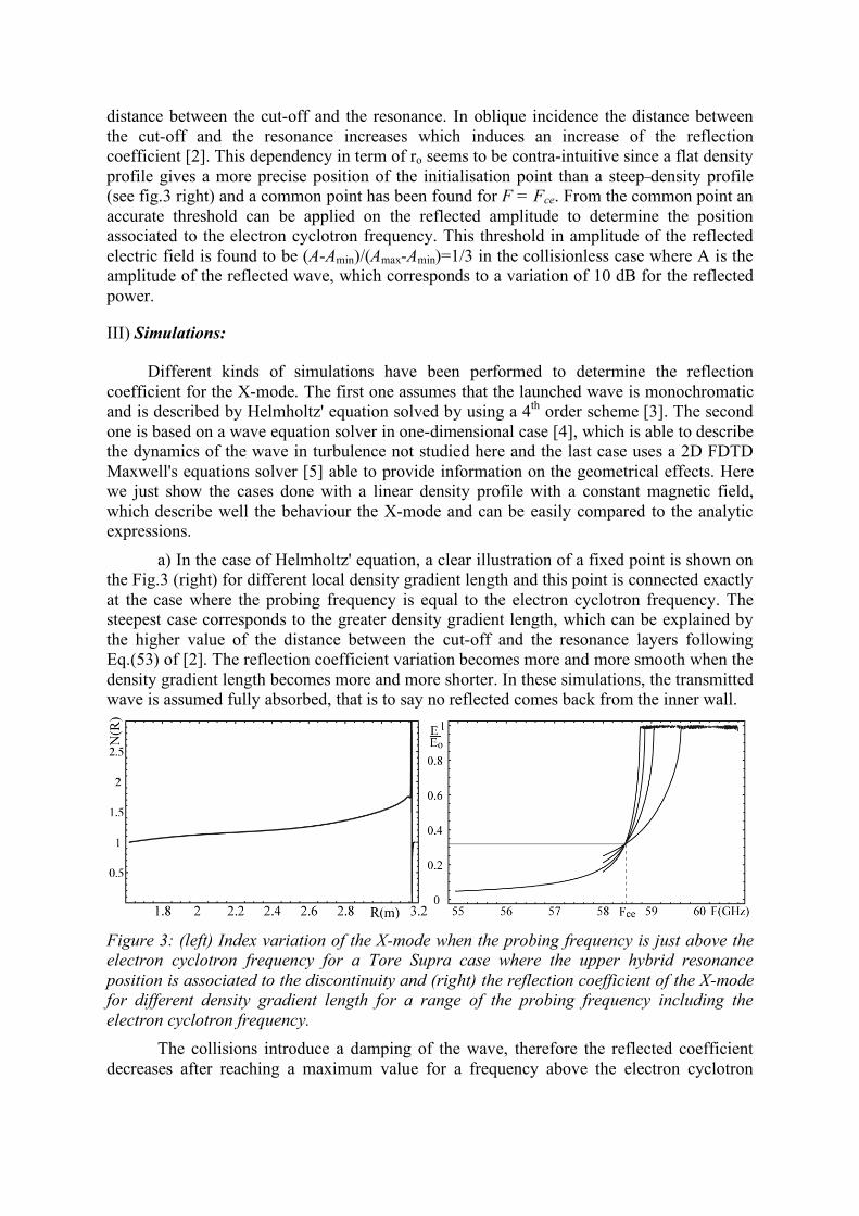
distance between the cut-off and the resonance. In oblique incidence the distance between the cut-off and the resonance increases which induces an increase of the reflection coefficient [2]. This dependency in term of ro seems to be contra-intuitive since a flat density profile gives a more precise position of the initialisation point than a steep density profile (see fig.3 right) and a common point has been found for F = Fce. From the common point an accurate threshold can be applied on the reflected amplitude to determine the position associated to the electron cyclotron frequency. This threshold in amplitude of the reflected electric field is found to be (A-Amin)/(Amax-Amin)=1/3 in the collisionless case where A is the amplitude of the reflected wave, which corresponds to a variation of 10 dB for the reflected power.
III) Simulations:
Different kinds of simulations have been performed to determine the reflection coefficient for the X-mode. The first one assumes that the launched wave is monochromatic and is described by Helmholtz' equation solved by using a 4th order scheme [3]. The second one is based on a wave equation solver in one-dimensional case [4], which is able to describe the dynamics of the wave in turbulence not studied here and the last case uses a 2D FDTD Maxwell's equations solver [5] able to provide information on the geometrical effects. Here we just show the cases done with a linear density profile with a constant magnetic field, which describe well the behaviour the X-mode and can be easily compared to the analytic expressions.
a) In the case of Helmholtz' equation, a clear illustration of a fixed point is shown on the Fig.3 (right) for different local density gradient length and this point is connected exactly at the case where the probing frequency is equal to the electron cyclotron frequency. The steepest case corresponds to the greater density gradient length, which can be explained by the higher value of the distance between the cut-off and the resonance layers following Eq.(53) of [2]. The reflection coefficient variation becomes more and more smooth when the density gradient length becomes more and more shorter. In these simulations, the transmitted wave is assumed fully absorbed, that is to say no reflected comes back from the inner wall.
Figure 3: (left) Index variation of the X-mode when the probing frequency is just above the electron cyclotron frequency for a Tore Supra case where the upper hybrid resonance position is associated to the discontinuity and (right) the reflection coefficient of the X-mode for different density gradient length for a range of the probing frequency including the electron cyclotron frequency. The collisions introduce a damping of the wave, therefore the reflected coefficient decreases after reaching a maximum value for a frequency above the electron cyclotron

frequency. This reduction of the reflected coefficient is associated to the wave absorption including resonant absorption [2] and increases with the probing frequency due to the fact that the path length in plasma increases as the cut-off layer becomes deeper and deeper.
b) The wave equation solver permits to have in one run directly access to the reflected wave behaviour over the frequency range used by a frequency sweep reflectometer. However it is more difficult to compute the reflection coefficient to due the fact that the probing frequency has to be recover in the reflected signal, which corresponds to a mix different frequencies coming from different positions (cut-off and resonance). A time delay exists between these different positions that is converted in frequency shift due to the frequency sweep. The effect can be enhanced when the cut-offs of the lower and upper branch of X-mode are present at the same time as shown on Fig.4 (right). However the same behaviour of the Helmholtz cases has been recovered for different density gradient length but the picture is less clear due to the frequency mixing.
Figure 4: Reflected electric field of the X-mode as a function of the probing frequency for the case of high magnetic field intensity (left) and intermediate magnetic field intensity (right) where the peak for F<Fce corresponds to the lower-branch reflection and F>Fce to the upper-branch reflection.
c) The use of the 2D permits to evaluate the geometrical effects, which introduce a spatial evolution of the probing wave depending of the radiation pattern. The electric field of the probing wave exhibits a structure with the same characteristics seen in one-dimensional case with damping (geometrical effect driving a decrease of the probing wave amplitude due to the radiation wave pattern of the antenna in the case of unfocused beam). The reflected wave coming back into the receiver shows a maximum of the amplitude above the electron cyclotron frequency and then decreases for the increasing probing frequency. At the same time, both branches of the X-mode can be observed, the upper-branch close to the horn and at lower level more inside the plasma the lower branch. A more careful look on the electric field structure permits to see that the oblique wave are more reflected than those following the normal incidence. That can be easily explained by the increase of the distance between the cut-off and the resonance layers [2].

Figure 5: Cut-offs of the lower and upper branches for the simulation parameters (left) and 2D electric field structure of the X-mode at 32 GHz for the probing frequency where the reflection of the upper branch is close the edge of the plasma at 25λo.
IV) Discussion: A simple analysis shows that a point independent of the local value of the density gradient length can be found assuming that the magnetic field stays constant. This analysis gives also a criterion on the amplitude to determine when the electron frequency is reached and then knowing the magnetic field topology an initialization point can be fixed from the amplitude variation. This initialization should be corroborated by the measurement of the time of flight, which is not easy when there is frequency mixing. A new data processing method can help us to discriminate the two different reflected signals due to the different emission time [6]. The more precise is the determination of the electron cyclotron location the more accurate will be the density profile reconstruction. One possibility is to use the criterion provided by the index analysis where the amplitude of the received signal is equal to 1/3 reflection in the framework of 1D analysis. Such analysis has to be extended to take into account multi-dimensional effects, however this study provides a way to find more general criterion.
References:
[1] F. Clairet, C. Bottereau, J.M. Chareau, R. Sabot Review of Scientific Instruments (2003) 74, 1481-1484.
[2] R.B. White, F.F. Chen, Plasma Phys. (1974) 16, 565-587.
[3] C. Fanack et al, Plasma Phys. Cont. Fusion (1996), 38, 1915-1930.
[4] S. Hacquin et al, J. of Computational Physics (2001) 174, 1-11.
[5] F. da Silva et al, this conference (2009).
[6] F. Briolle et al, this conference (2009).