an sms-based student response system -...
TRANSCRIPT

An SMS-based Student Response System
Submitted in partial ful�lment
of the requirements of the degree of
BACHELOR OF SCIENCE (HONOURS)
of Rhodes University
David Kyle Brown
Grahamstown, South Africa
November 2012

Abstract
Student Response Systems are wireless systems that provide lecturers with the ability
to actively engage students in the classroom. They work by providing students with a
personal response unit, which students subsequently use to respond to questions posed
during the lecture. The dependency of current Student Response Systems on personal
response units is less than desirable. As class sizes increase, supplying su�cent devices
can become expensive. This project investigates the feasability of creating an SMS-based
Student Response System that is extendable and exposes its functionality over HTTP.
This is achieved by developing a prototype system that satis�es the above objective.
Analysis of the system reveals that it can be implemented at a low cost and that it can
help provide lecturers with realtime feedback with regard to areas that students may be
struggling with. Load tests reveal that the system is more than capable of being used
in an academic environment. It can therefore be concluded that an SMS-based Student
Response System is both feasible and bene�cial to students and lecturers alike.

ACM Computing Classi�cation System Classi�cation
Thesis classi�cation under the ACM Computing Classi�cation System (1998 version, valid
through 2012):
C.2.1 [Network Architecture and Design]: Centralized networks
H.2.1 [Logical Design]: Data Models
H.3.5 [Online Information Services]: Web-based services
K.3.1 [Computer Uses in Education]: Computer-assisted instruction (CAI)
General Terms: Web-based API, SMS Gateway, Global System for Mobile communi-
cation (GSM), AT Commands, Automation

Acknowledgements
I would like to acknowledge the �nancial and technical support of Telkom, Tellabs,
Stortech, Genband, Easttel, Bright Ideas 39 and THRIP through the Telkom Centre
of Excellence in the Department of Computer Science at Rhodes University.
I would also like to thank my supervisor, James Connan, for the advice, guidance and
insights o�ered throughout the year.

i

Contents
1 Introduction 1
1.1 Background . . . . . . . . . . . . . . . . . . . . . 1
1.2 Problem Statement . . . . . . . . . . . . . . . . . 2
1.3 Research Goals . . . . . . . . . . . . . . . . . . . 2
1.3.1 Approach . . . . . . . . . . . . . . . . . . 3
1.4 Thesis Organization . . . . . . . . . . . . . . . . 3
2 Literature Review 4
2.1 Introduction . . . . . . . . . . . . . . . . . . . . 4
2.2 Previous Work on Student Response Systems . . . . . 4
2.2.1 The Impact of Clickers . . . . . . . . . . . 5
2.2.2 Limitations of Current Student Response Systems 5
2.2.3 Student Performance . . . . . . . . . . . . . 5
2.3 The GSM Network . . . . . . . . . . . . . . . . . . 6
2.4 The OpenBTS Project . . . . . . . . . . . . . . . . 6
2.4.1 Why GSM? . . . . . . . . . . . . . . . . . . 7
2.4.2 GNURadio . . . . . . . . . . . . . . . . . . 8
2.4.3 SIP and Asterisk . . . . . . . . . . . . . . 9
2.4.4 Legal Issues . . . . . . . . . . . . . . . . 9
2.4.5 Testing with Hardware . . . . . . . . . . . . 10
2.5 SMS Gateway . . . . . . . . . . . . . . . . . . . . 11
2.6 GSM Modem . . . . . . . . . . . . . . . . . . . . . 11
2.7 Android . . . . . . . . . . . . . . . . . . . . . . 12
2.7.1 Data Storage . . . . . . . . . . . . . . . . 13
2.8 Summary . . . . . . . . . . . . . . . . . . . . . . 14
3 System Design 15
3.1 Introduction . . . . . . . . . . . . . . . . . . . . 15
ii

CONTENTS iii
3.2 System Overview . . . . . . . . . . . . . . . . . . 16
3.3 Design Decisions . . . . . . . . . . . . . . . . . . 18
3.3.1 HTTP Interface . . . . . . . . . . . . . . . 18
3.3.1.1 Serialization . . . . . . . . . . . . 18
3.3.2 Environment . . . . . . . . . . . . . . . . . 19
3.4 Database Design . . . . . . . . . . . . . . . . . . 19
3.5 HTTP Gateway Design . . . . . . . . . . . . . . . . 21
3.6 SMS Gateway . . . . . . . . . . . . . . . . . . . . 22
3.6.1 The smshandler package . . . . . . . . . . . 23
3.6.2 Implications . . . . . . . . . . . . . . . . 23
3.7 The Message Class and the SMSMessage Class . . . . 24
3.8 The Message Protocol . . . . . . . . . . . . . . . . 25
3.9 Android Application . . . . . . . . . . . . . . . . 26
3.10 SMS Validity . . . . . . . . . . . . . . . . . . . . 26
3.11 Resubmitting Tasks and Roll Calls . . . . . . . . . 27
3.12 Summary . . . . . . . . . . . . . . . . . . . . . . 27
4 Implementation 29
4.1 Introduction . . . . . . . . . . . . . . . . . . . . 29
4.2 Setting up the OpenBTS Network . . . . . . . . . . 30
4.2.1 Hardware Requirements . . . . . . . . . . . . 30
4.2.2 Preparing the PC . . . . . . . . . . . . . . 31
4.2.3 Installing GNU Radio . . . . . . . . . . . . 31
4.2.4 Testing GNU Radio . . . . . . . . . . . . . . 32
4.2.5 Installing OpenBTS . . . . . . . . . . . . . 32
4.2.6 Installing Smqueue . . . . . . . . . . . . . 32
4.2.7 Configuration . . . . . . . . . . . . . . . . 33
4.2.8 RX failed to tune . . . . . . . . . . . . . . 33
4.3 Installing the External Clock . . . . . . . . . . . 33
4.3.1 Clocktamer . . . . . . . . . . . . . . . . . 34
4.3.2 Software Patches . . . . . . . . . . . . . . 34
4.3.3 Hardware failure . . . . . . . . . . . . . . 35
4.4 The GSM Modem . . . . . . . . . . . . . . . . . . . 35
4.4.1 Communicating with the Modem . . . . . . . . 35
4.4.1.1 AT Commands for sending an SMS . . . 36
4.4.1.2 AT Commands for Reading Messages . . 37
4.4.2 AT Commands for Deleteing a Message . . . . . 37

CONTENTS iv
4.5 HTTP Gateway . . . . . . . . . . . . . . . . . . . . 37
4.5.1 HTTP Interface . . . . . . . . . . . . . . . 38
4.5.2 Data Model . . . . . . . . . . . . . . . . . 39
4.5.3 The smshandler package . . . . . . . . . . . 39
4.5.4 The API . . . . . . . . . . . . . . . . . . . 39
4.6 The Client Application - RUAtLectures . . . . . . . 40
4.7 Android Application . . . . . . . . . . . . . . . . 40
4.7.1 Requirements for developing Android applications 42
4.7.2 SMS Functionality . . . . . . . . . . . . . . 42
4.8 SMS Costs . . . . . . . . . . . . . . . . . . . . . 43
4.9 Summary . . . . . . . . . . . . . . . . . . . . . . 43
5 Results And Testing 45
5.1 Introduction . . . . . . . . . . . . . . . . . . . . 45
5.2 Load Testing . . . . . . . . . . . . . . . . . . . . 45
5.3 Analysis . . . . . . . . . . . . . . . . . . . . . . 46
5.4 RUAtLectures . . . . . . . . . . . . . . . . . . . . 48
5.5 Summary . . . . . . . . . . . . . . . . . . . . . . 51
6 Conclusion 52
6.1 Project Summary . . . . . . . . . . . . . . . . . . 52
6.2 Revisiting the Objectives . . . . . . . . . . . . . 52
6.3 Future Work . . . . . . . . . . . . . . . . . . . . 53
A Assembling the USRP 55
B Commands to install Boost 1.44.0 from source 56
C Other GNU Radio dependencies 57
D Instructions for Installing GNU Radio 58
E Testing GNU Radio 60
E.1 USRP Benchmark . . . . . . . . . . . . . . . . . . . 60
E.2 USRP FFT . . . . . . . . . . . . . . . . . . . . . . 60
F OpenBTS Installation Instructions 63
G Configuration Modifications 65

CONTENTS v
G.1 OpenBTS Configuration . . . . . . . . . . . . . . . 65
G.2 Asterisk Configuration . . . . . . . . . . . . . . 66
G.3 smqueue Configuration . . . . . . . . . . . . . . . 67
H USRP_FFT Patch 68
I Web API 70
J Psuedocode for Sending an SMS 73
K Java Code for SMS functionality within Android Application 75

List of Figures
2.1 Main components of a GSM network . . . . . . . . . . . . . . . . . . . . . 6
2.2 OpenBTS System Overview . . . . . . . . . . . . . . . . . . . . . . . . . . 7
2.3 GNURadio framework . . . . . . . . . . . . . . . . . . . . . . . . . . . . . 9
2.4 HACS Framework Overview . . . . . . . . . . . . . . . . . . . . . . . . . . 12
3.1 Lecture and Course Management System Overview . . . . . . . . . . . . . 17
3.2 Context Diagram . . . . . . . . . . . . . . . . . . . . . . . . . . . . . . . . 17
3.3 Database Inputs . . . . . . . . . . . . . . . . . . . . . . . . . . . . . . . . . 20
3.4 Database Design . . . . . . . . . . . . . . . . . . . . . . . . . . . . . . . . 21
3.5 HTTP Gateway . . . . . . . . . . . . . . . . . . . . . . . . . . . . . . . . . 22
3.6 SMS Gateway . . . . . . . . . . . . . . . . . . . . . . . . . . . . . . . . . . 24
3.7 Flow chart for incoming message . . . . . . . . . . . . . . . . . . . . . . . 27
4.1 Re-clocking modi�cations . . . . . . . . . . . . . . . . . . . . . . . . . . . 34
4.2 HTTP Gateway Interactions . . . . . . . . . . . . . . . . . . . . . . . . . . 40
4.3 Android Con�guration UI . . . . . . . . . . . . . . . . . . . . . . . . . . . 41
4.4 Android Registration UI . . . . . . . . . . . . . . . . . . . . . . . . . . . . 41
4.5 Android Task UI . . . . . . . . . . . . . . . . . . . . . . . . . . . . . . . . 42
vi

LIST OF FIGURES vii
4.6 The Completed Lecture and Course Management System . . . . . . . . . . 44
5.1 Load Testing - Request Time . . . . . . . . . . . . . . . . . . . . . . . . . 46
5.2 Load Testing - Average Request Time . . . . . . . . . . . . . . . . . . . . . 46
5.3 RUAtLectures Home Page . . . . . . . . . . . . . . . . . . . . . . . . . . . 48
5.4 RUAtLectures Courses Page . . . . . . . . . . . . . . . . . . . . . . . . . . 48
5.5 RUAtLectures Students Page - Tasks . . . . . . . . . . . . . . . . . . . . . 49
5.6 RUAtLectures Students Page - Roll Calls . . . . . . . . . . . . . . . . . . . 49
5.7 RUAtLectures Task Results . . . . . . . . . . . . . . . . . . . . . . . . . . 50
5.8 RUAtLectures Attendance Registers . . . . . . . . . . . . . . . . . . . . . . 50
6.1 System Summary . . . . . . . . . . . . . . . . . . . . . . . . . . . . . . . . 53
E.1 Frequency 1783.8 MHz is not used [14] . . . . . . . . . . . . . . . . . . . . 61
E.2 Frequency 1783.8 MHZ is used [14] . . . . . . . . . . . . . . . . . . . . . . 62
I.1 Courses . . . . . . . . . . . . . . . . . . . . . . . . . . . . . . . . . . . . . 70
I.2 Answers . . . . . . . . . . . . . . . . . . . . . . . . . . . . . . . . . . . . . 71
I.3 RollCalls . . . . . . . . . . . . . . . . . . . . . . . . . . . . . . . . . . . . . 71
I.4 Tasks . . . . . . . . . . . . . . . . . . . . . . . . . . . . . . . . . . . . . . . 71
I.5 SMSGateway . . . . . . . . . . . . . . . . . . . . . . . . . . . . . . . . . . 72
I.6 Students . . . . . . . . . . . . . . . . . . . . . . . . . . . . . . . . . . . . . 72

List of Code Listings
1 Install Boost - Linux Terminal Commands . . . . . . . . . . . . . . . . . . 56
2 Install required packages for GnuRadio - Linux Terminal Command . . . . 57
3 Permissions to add to AndroidManifest.xml . . . . . . . . . . . . . . . . . 75
4 sendSMS Algorithm (Java) . . . . . . . . . . . . . . . . . . . . . . . . . . . 76
5 <receiver> element . . . . . . . . . . . . . . . . . . . . . . . . . . . . . . . 76
6 SMSReciever class . . . . . . . . . . . . . . . . . . . . . . . . . . . . . . . 77
viii

Chapter 1
Introduction
1.1 Background
A Student Response System (SRS) is a wireless system that provides lecturers with the
ability to actively engage students in a classroom. These systems allow students to respond
to questions posed during a lecture via a wireless device known as a personal response
unit, or clicker [22]. The dependancy of the system on providing clickers to each and every
student in the class introduces a cost constraint. For this reason, it would be convenient
to develop a system on a platform that is already available and accessible to all students.
As of February 2012, there are 5.9 billion mobile subscribers, globally [25, 19]. This
translates to 87% of the world's population. Despite this, sales of mobile devices are still
on the rise and growth in this area is being led by smartphones. SMS remains the most
popular form of communication with 8 trillion SMS messages being sent during 2011[25].
Ubiquitous access and low implementation costs make SMS the ideal platform for building
an SRS. Students are also familiar with the operation of cellphones and so the learning
curve for such a system would be minimal. One challenge that must be overcome, however,
is that of SMS transmission costs. Students should not be expected to bare these costs
themselves.
The goal of this project is to develop a SRS that allows students to use SMS to engage
themselves in lectures.
1

1.2. PROBLEM STATEMENT 2
1.2 Problem Statement
Other than with pen and paper, there is no cost-e�ective and e�cient means of taking roll
call or holding quizzes in large classes. For a roll call, calling out names is slow and tedious
and passing around a list makes it simple for students to cheat by signing their friends
names for them [30]. For a quiz, passing out multiple-choice answer sheets or collecting
written answers wastes even more valuable lecture time. In an environment where all the
students have computers and can answer online quizzes, this problem is easy to solve.
Answering the quiz will automatically verify that the student was in attendance. In a
lecture theatre, however, the only form of network communication students have is via
their cellphones and lecturers cannot expect their students to spend their own airtime
answering questions via SMS at normal network rates. The purpose of this project is to
investigate whether it is possible to set up an Student Response System that makes use
of SMS, at a reasonable price, and to determine whether this system would be a viable
option to solve the problem at hand.
1.3 Research Goals
The Objectives of this project are as follows:
1. To develop a modular network architecture that will provide a platform for creating
an SMS-based Student Response System.
2. To expose the functionality of the system as a web service.
3. To develop a prototype client application to make use of the exposed web service
4. To determine whether this system could be used to solve the issues de�ned in the
problem statement above.
5. To develop an application for Android that can be used to answer quizzes over the
network and eliminate human error in answer formats.
Future extensions to this work could include adding greater functionality to the web
service and providing ways, over and above SMS, to answer quizzes.

1.4. THESIS ORGANIZATION 3
1.3.1 Approach
The following approach will be taken for the research:
1. relevant background literature is identi�ed and reviewed
2. the network architecture and underlying database is designed
3. the back-end system is developed
4. a prototype client is developed to test the functionality of the exposed web service
5. a scope for future extensions is identi�ed
1.4 Thesis Organization
This thesis has been organised into the following chapters:
Chapter 2 discusses relevant work and technologies in the �elds of GSM communications.
Chapter 3 describes the the design of the network and database as well as that of the
API that will be exposed to the web.
Chapter 4 describes the implementation of the Student Response System as well as the
di�culties encountered during implementation and the workarounds used.
Chapter 5 provides an analysis of the implemented system and discusses areas in which
project goals were either met or not met.
Chapter 6 provides a summary of the aims and �ndings of the research, outlining the
conclusions drawn. Lastly, it discusses the scope for future extensions to the project.

Chapter 2
Literature Review
2.1 Introduction
Student Response Systems (SRS) have been garnering an increasing amount of atten-
tion over recent years as they allow facilitators to more easily engage with large classes.
Limitations of current systems is that they require members of the class or audience to
be presented with a personal response unit. This is less than desirable due to the cost
implications of such an endeavor when class sizes become very large.
To solve this problem, this chapter looks at two ways of providing SMS functionality to
a system. Firstly, it discusses the setting up of a picocell using OpenBTS to provide
GSM coverage over a small area such as a lecture theatre. And secondly, it looks into
connecting a GSM modem to the system to provide SMS functionality.
Each method has its own advantages and disadvantages and as such, a decision was made
to set up both methods in parallel.
2.2 Previous Work on Student Response Systems
Student Response Systems are increasingly being used in tertiary education institutions
around the world [22]. What is important to note is that these systems are not only in
place to help the students to engage with the course, but also to help lecturer to facilitate
the course. The following section looks at studies that have been done on the impact of
SRSs in the classroom environment.
4

2.3. THE GSM NETWORK 5
2.2.1 The Impact of Clickers
As the number of students per class grows, the ability of a facilitator to actively engage
all the students diminishes [16]. There is a general agreement amongst authors that,
together with appropriate pedagogical methadologies, SRSs promote learning. Several
studies have found that students have a positive perception of the technology and that
it greatly improves student participation and enthusiasm [16]. In a survey done by [22],
there was a substantial increase, amongst lecturers and students alike, in perceptions and
opinions about engagement and participation in classes. Notably, lecturers found that
clickers allowed them to stimulate discussion in class based on data received.
2.2.2 Limitations of Current Student Response Systems
Limitations of SRS systems include:[16]
• Reliability of the system
• Cost
• Technical knowledge
• Interruption in the �ow of the class
2.2.3 Student Performance
Although most studies have shown an increase in enthusiasm and participation amongst
students using an SRS, �ndings with regard to student performance have been mixed. In
certain cases, little to no improvement was recorded with regard to examination scores
[26], but, in studies done by [17, 27, 29], positive impacts were recorded in psychology,
chemistry and management students respectively. The authors of these papers did, how-
ever, caution that improvements may not have been as a result of the SRSs and that
further research was necessary.

2.3. THE GSM NETWORK 6
Figure 2.1: Main components of a GSM network
2.3 The GSM Network
A GSM network is a complex system consisting of a number of components (see Figure
2.1), with the last section being the Base Transceiver Station (BTS)[23].
Transmitting and receiving the Radio Frequency (RF) signals to and from the user termi-
nals is the responsibility of the BTS. As depicted in Figure 2.1, the BTSs' are controlled
by a Base Station Controller (BSC). This in turn is connected to a Mobile Switching
Centre/Visitor Location Register, whose responsibility it is to authenticate users against
the database (HLR - Home Location Register, AuC - Authentication Centre) [23].
2.4 The OpenBTS Project
The OpenBTS project is an e�ort to construct an open-source Unix application that uses
the Universal Software Radio Peripheral (USRP) to present a GSM air interface ( also
known as a �Um�) to standard GSM handsets and uses the Asterisk VoIP PBX to connect
calls [20, 23, 15].
The history of OpenBTS begins in mid 2007 when Kestrel Signal Processing, Inc. began
writing an implementation of a GSM basestation with the goal of creating a new kind of
inexpensive, light-weight cellular network that could be used to connect rural and sparsely
populated areas to existing cellphone infrastructure. David Burgess and Harvind Samra
were the initial developers of the project and contributed most of the code for layers 1
and 2 of the GSM stack before the �rst public release of the source code [18].
2.4. THE OPENBTS PROJECT 7
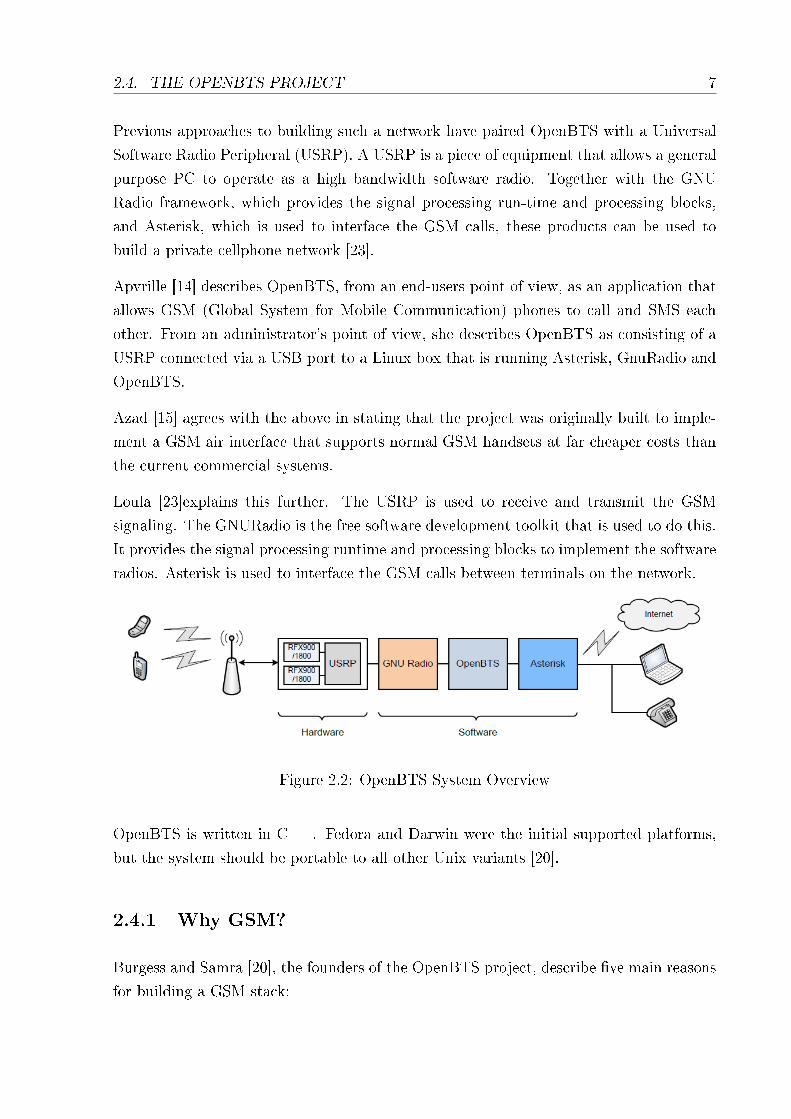
Previous approaches to building such a network have paired OpenBTS with a Universal
Software Radio Peripheral (USRP). A USRP is a piece of equipment that allows a general
purpose PC to operate as a high bandwidth software radio. Together with the GNU
Radio framework, which provides the signal processing run-time and processing blocks,
and Asterisk, which is used to interface the GSM calls, these products can be used to
build a private cellphone network [23].
Apvrille [14] describes OpenBTS, from an end-users point of view, as an application that
allows GSM (Global System for Mobile Communication) phones to call and SMS each
other. From an administrator's point of view, she describes OpenBTS as consisting of a
USRP connected via a USB port to a Linux box that is running Asterisk, GnuRadio and
OpenBTS.
Azad [15] agrees with the above in stating that the project was originally built to imple-
ment a GSM air interface that supports normal GSM handsets at far cheaper costs than
the current commercial systems.
Loula [23]explains this further. The USRP is used to receive and transmit the GSM
signaling. The GNURadio is the free software development toolkit that is used to do this.
It provides the signal processing runtime and processing blocks to implement the software
radios. Asterisk is used to interface the GSM calls between terminals on the network.
Figure 2.2: OpenBTS System Overview
OpenBTS is written in C++. Fedora and Darwin were the initial supported platforms,
but the system should be portable to all other Unix variants [20].
2.4.1 Why GSM?
Burgess and Samra [20], the founders of the OpenBTS project, describe �ve main reasons
for building a GSM stack:

2.4. THE OPENBTS PROJECT 8
1. The USRP can be easily adapted to perform the role of a GSM transceiver and, if
reworked, the hardware can be used as a carrier-grade radio for use in a software
BTS.
2. From experience, they knew that a GSM protocol stack, including the software
radio, could be implemented in less than 15000 lines of C++ code.
3. Much of the need for network infrastructure can be eliminated by moving the tele-
phone switching functions, calling features and mobility management functions into
a software PBX (Asterisk).
4. Every year, rich nations discard many functional GSM handsets that could be reused
in developing countries.
5. The cost of service in o�-grid environments can be substantially reduced as, with
good hardware design and economical software design, a low-capacity GSM cell can
be run from micro wind turbines or solar panels.
The founders state that they chose GSM over the newer CDMA as it is a proven technology
and 80% of the world's carriers still use it. The GSM speci�cation is also publicly available
and most of the important patents will soon expire. CDMA, on the other hand, is highly
valued intellectual property and getting a copy of the speci�cation costs several hundred
dollars. It's physical layers are also too complex for an inexpensive all-software radio and
do not scale well [20].
2.4.2 GNURadio
�GNURadio is a free software toolkit licensed under the GPL for implementing software-
de�ned radios� [31].
Although a port, providing limited functionality, has been produced for Windows, general
GNUradio support is for Linux. GNURadio uses a graph to represent a transceiver; the
vertices are the signal processing blocks and the data �ow between them is represented
by the edges. There are several building blocks for information and signal processing
included in the package [31].
The graphs are built and run in Python while the lower-level programming, e.g. the
creation of the blocks, is done in C++. SWIG2 is used as the interface between the high
and low levels[31]. The framework is depicted in Figure 2.3.

2.4. THE OPENBTS PROJECT 9
Figure 2.3: GNURadio framework
GNURadio allows engineers to implement a number of technologies in the software domain
although there are certain limitations that can arise and the process can be tedious[31].
2.4.3 SIP and Asterisk
Azad [15] de�nes Asterisk as an IP PBX with integrated VoIP gateway, call centre system,
conference bridge and voice mail server. He states that the Asterisk PBX is used for all
call control functions as well as certain mobility management tasks and that it makes use
of subscriber IMSIs as Session Initiation Protocol (SIP) usernames. This is backed up by
[20], which states that the Asterisk PBX is used for nearly all call control functions. It
is also an essential part of the mobility management. By pushing as much of the control
layer as is possible into the Asterisk PBX, Asterisk is instrumental in the simpli�cation
of OpenBTS. To do this, the subscriber IMSIs (International Mobile Subscriber Identity)
are used as SIP usernames. Each GSM handset is then presented to Asterisk as a SIP
client [20, 15].
OpenBTS's control layer is largely there to perform mapping operations [20]:
• �GSM location updates get mapped to SIP registrations�
• �Call connection transactions get mapped to corresponding SIP transactions�
• �GSM tra�c channels get mapped to RTP channels�
2.4.4 Legal Issues
Certain GSM bandwidths are regulated by authorities [14]. Regulations may vary de-
pending on the country. Users should check what is authorized in their country if they

2.4. THE OPENBTS PROJECT 10
require a test license or a given channel etc. Burgess et al. [20] agrees with [14] on
this matter, stating that radio transmissions are regulated everywhere on the planet. It
is highly recommended that, before using any radio equipment or any of the OpenBTS
software, the user checks the local telecom and radio regulations [20]. According to [20]:
1. If you are transmitting in a licensed band and your transmissions are detectable
more than a few metres away then you are probably breaking the law.
2. If you are receiving signals from a licensed public network in su�cient volume to
comprehend conversations, determine the contexts of data transmissions or deter-
mine the identities of users then you are probably breaking the law.
3. If you are outside of North America and Europe and using VoIP over a public
network, you may be breaking the law.
The OpenBTS project is, so much as possible, licensed under the BSD license. Some
modules are subject to the GPL, for example, �parts of the system that link to the USRP
drivers� [20].
The 3rd Generation Partnership Project (3GPP) of the European Telecommunications
Standards Institute (ETSI) controls the GSM standard. There are about 200 patents
on important parts of the standard, held by ETSI member companies. To use GSM
commercially, a license must be arranged with the holders of these patents [20, 15].
Azad [15] con�rms the statements made above, saying that, depending on where you
implement the OpenBTS network, one needs to understand that there may be a number
of legal implications that must �rst be addressed.
2.4.5 Testing with Hardware
Many good software unit-testing tools are provided by the OpenBTS team, but the only
real way to verify whether the network is really working or not is to test it with real
phones. For this, an RF testing environment is required that allows tests on your network
to be run without breaking any laws [20]:
1. Closed RF Environments
An environment in which all signals are contained within Faraday cages or cables
[20].

2.5. SMS GATEWAY 11
2. ISM Bands
Certain parts of the world will allow up to 1W of transmission in unlicensed bands,
allowing for a low range GSM network to be constructed.
3. Limited Power
It may be possible, depending on regulations in the area, to operate the BTS at
very low power over a range of a couple of metres. Unfortunately, this strategy may
add a few hundred dollars to the price of the development kit as you will need a
preamp on the input of the USRP. This is because the receiver on the USRP is not
very sensitive and if the transmit power on the handset is too low, the receiver will
not receive the uplink signal [20].
4. Fallow Spectrum
In rural areas there are plenty of open ARFCNs that you may be able to get tem-
porary or experimental licenses for [20].
2.5 SMS Gateway
In Generic Information System Using SMS Gateway, [28] shows the versatility that using
an SMS gateway can provide. The gateway receives SMS messages of a certain format and,
based on the content of the message, forwards the message to a speci�c application. Using
this framework, additional functionality can be added without changing the source code
of the gateway, providing for a simple, scalable solution for adding services to an existing
system. All that the system administrator need do is provide the routing information so
that the gateway knows where to forward the SMS to.
The system proposed by [28] retrieves information from a speci�c database based on the
information provided in the SMS. In the same way, an SMS gateway can be used to
route information to di�erent applications. If the underlying system is designed correctly,
an SMS gateway can provide a ubiquitous and easily extendable platform for providing
remote services.
2.6 GSM Modem
A GSM modem is a plug-and-play device that, when attached to a PC, can be used to
send and receive SMSs. Essentially, it bridges the gap between the computer and the

2.7. ANDROID 12
GSM network. In SMS Based Wireless Home Appliance Control System (HACS) for
Automating Appliances and Security, [24] makes use of a GSM modem to create a system
for remotely controlling home appliances via SMS. The GSM modem is connected to a
PC via an RS232 port. Messages received by the modem can be read in by the PC and
actions are taken accordingly.
Figure 2.4: HACS Framework Overview
Using this principle, GSM modems become extremely useful. The ubiquity of GSM net-
works means that systems based on this technology can be accessed remotely from just
about anywhere on the planet. Once set up, sending commands is as simple as sending
an SMS.
According to [24], it is possible to purchase equipment that combines the PC and GSM
modem, along with a UPS and charging system, in one self-contained hardware device.
This device will not, therefore, be prone to electric failure.
2.7 Android
An SMS-based system implies that SMSs will have to be of a certain format for the system
to be able to process them. The frequency of human error means that situations will often
arise where a student makes a mistake in the format of the SMS. In such cases, the system

2.7. ANDROID 13
will be unable to parse the SMS and the SMS will be discarded. To curb this, it would
be useful to have a mobile application to abstract the formatting of the message from the
student.
Due to its popularity, Android was chosen as the platform for developing a proof-of-
concept application. Android is currently the most popular mobile platform in the world
[1]. This is backed up by [21], who states that Android is currently the �No. 1 smartphone
operating system�.
An important area to consider when creating an application on an Android application
is how to store persistent data. The following section details the options available.
2.7.1 Data Storage
There are �ve main options to be considered when selecting a means to store persistent
application data [3]:
• Shared Preferences
Shared preferences allows for private primitive data to be stored in key-value pairs. Prim-
itive data refers to: booleans, �oats, ints, longs, and strings. This data will persist, even
if a session is killed.
• Internal Storage
Internal storage allows for private data to be saved directly to the device's internal mem-
ory. These �les can only be accessed by the application that stored them and when that
application is uninstalled, the �les are removed.
• External Storage
All Android devices support some kind of shared external storage. This can be in the
form of internal storage or removable storage media such as an SD card. Files saved to
the external storage are world-readable and can be modi�ed by the user when they enable
USB mass storage to transfer �les on a computer.

2.8. SUMMARY 14
• SQLite Database
SQLITE databases are fully supported by the Android OS.
• Network Connection
The network can be used to retrieve data from web-based services. An advantage of this
approach is that the devices own memory is not used for storage. A disadvantage of this
is that when the network is down or there is no access to it, the data will be unavailable.
2.8 Summary
In summary, SRSs are a good way to increase student participation and engagement in
large classes. Studies have suggested that they could even be responsible for improvements
in test scores, although further research is required in this area. The limitations of current
SRSs include cost, reliability, lack of technical knowledge, and interruption of class �ow.
To create a cost-e�ective solution to building an SRS, it makes sense to use a GSM network
as the platform. This is due to the pervasive adoption of GSM networks and SMS around
the world. Two methods were investigated to create a system with SMS functionality.
The �rst method is to use OpenBTS to create a picocell that students can connect to via
their cellphones when arriving at a lecture. This method has the disadvantage of requiring
expensive equipment and a license to implement, but SMSs on such a network would be
free. The second method entails using a GSM modem to provide SMS functionality to
the system. This method has no legal issues and is cheap to implement, but it has the
disadvantage that SMSs will be charged at normal network rates. The decision was made
to implement both methods along side each other in an attempt to take advantage of the
strengths of each.
Lastly, it was noted that, due to the need for an unambiguous SMS format, it would be
useful to have a mobile application that could format SMSs using a designed protocol.
Due to its large global market, Android was chosen as the platform to develop a proof-
of-concept application.

Chapter 3
System Design
3.1 Introduction
The aim of this project is to develop an easily extendable and modi�able SMS-based
SRS. The need for such a system is due to the limitations of current SRSs, which require
students to be provided with personal response units, or clickers. In large classes, this can
be expensive. The advantages of an SMS-based SRS include low implementation costs,
ease-of-use (users don't need to learn a new skill to use the system as it is based on SMS),
and extendability. Other than allowing students to remotely answer qustions and sign
attendance registers, it can help facilitators with their administrative duties, including
marking tests. It will also help to engage students and increase student participation in
lectures.
The system will be used by students to sign in for lectures and answer quizzes/tasks.
Students will do this via SMS. As such, the system must be able to handle two types of
messages from students: Tasks and RollCalls. With this information, the system should
be able to produce atendance registers and mark tasks.
One of the most important requirements of this system, other than having the ability to
e�ciently and e�ectively send and receive SMSs, is that it should be easily extendable,
allowing for future add-ons and improvements. A database must also be developed that
can be easily and e�ciently queried for information and a message protocol must be
designed so that the system can parse received SMSs. To make it easier for students to
comply with this protocol, a mobile application must be developed which will abstract
the details of the protocol and reduce room for error when sending SMSs. Lastly, the
15

3.2. SYSTEM OVERVIEW 16
system should expose an HTTP interface and provide an easy-to-use client application to
preview some of its functionality.
These requirements make for a system that is easy for students to use, encourages student
participation in class, discourages skipping of lectures, and lightens the administrative
load on lecturers. Being able to see student answers in real time will also help lecturers
stimulate discussions in class.
3.2 System Overview
The system designed to satisfy the above requirements consists of three main areas/modules,
namely:
1. SMS Gateway
2. Client Application
3. HTTP Interface/Gateway
A modular design was chosen to allow the system to be easily modi�ed and extended.
The goal is to allow for individual modules to be easily updated, removed and replaced
without having too much of an e�ect, if any, on the rest of the system.
An overview of the system is depicted in Figure 3.1. Di�erent modules can be linked
to and removed from the HTTP interface without a�ecting the overall system. As it
stands in Figure 3.1, the system receives data via SMS or via a client application using
HTTP. This architecture allows for more modules to be added in the future, perhaps
incorporating functionality to allow interaction with other protocols.
The system receives data from two sources, namely, students and facilitators.
Students interact with the system via SMS, sending in answers to tasks and responses
to roll calls. Facilitators interact with the system via the client application. They are
responsible for inputting student and course details, assigning students to courses, and
creating and managing the tasks and roll calls.
The system is responsible for marking tasks and outputting results, attendance registers
and useful statisitics. Figure 3.2 depicts these interactions.

17
Figure 3.1: Lecture and Course Management System Overview
Figure 3.2: Context Diagram

3.3. DESIGN DECISIONS 18
3.3 Design Decisions
While designing the system, certain decisions had to be made with regards to what tech-
nologies were going to be used and how the di�erent modules would interact.
3.3.1 HTTP Interface
Exposing an HTTP interface was chosen for the following reasons:
1. Exposing an HTTP interface as a means for interacting with the system means that
client applications can be built without regard to the platform.
2. HTTP has been used for communication over the World Wide Web since its incep-
tion. As such, it is used and understood by a broad audience.
3. Building HTTP interfaces is well-supported by many development environments
and there are many tools available to lighten the task.
4. Extending an HTTP interface is a quick and easy task meaning that it �ts in well
with the goal of having an easily extendable system.
3.3.1.1 Serialization
As a serialization format, JSON was chosen over XML for it's simplicity and speed.
The main advantages of XML are that it is unambigous and can be validated. Neither
of these advantages were deemed to be vitality important when it came to achieving the
goals set out for the course management system. XML is also very verbose, meaning that
it can be slow to read and can have a high overhead.
For the simple transmissions required by the course management system, the lightweight
JSON format was deemed more appropriate. JSON makes use of a key-value format,
which makes it is fast, simple and human readable.

3.4. DATABASE DESIGN 19
3.3.2 Environment
The system was hosted using Apache Tomcat on a machine running Ubuntu Linux 10.04.
Development of the system was done in Java. The reasons behind this were its platform-
independance and the wide array of libraries already available thanks to the large Java
community. As the system exposes an HTTP interface, the development of a client can
be done in the developers language of choice.
3.4 Database Design
The database is an essential part of the system and as such, it's design was an integral
part of the implementation.
In order to design any database, it is important to analyse the system requirements,
deducing where the inputs for the system are coming from and what they are.
Figure 3.3 depicts the sources of data and what each source is sending. As can be seen,
the system itself is is included as a source. Although the facilitators are responsible for
inputting the correct answers to the tasks they create and the students are responsible
for sending in their own answers to the questions posed within the task, it is the system
that is required to mark the tasks. For the sole purpose of e�ciency, the system will then
store the results of these tasks. This negates the need to remark a task everytime the
results are required by a user.
As mentioned above, students are responsible for inputting answers to questions posed in
tasks as well as registering their presence at a lecture by sending in the required data for
a roll call.
Facilitators are responsible for the administrative side of the system. They input students,
courses, roll calls and tasks as well as the correct answers for those tasks so that the system
can mark them. They are also responsible for assigning students to courses.

3.4. DATABASE DESIGN 20
Figure 3.3: Database Inputs
The database designed for the SRS is depicted in Figure 3.4. After inputting a task, a
facilitator can input answers for that task.
Courses consist of many tasks, rollcalls and students. The only details that need to be
recorded in the Courses table, however, are the course name and a code to identify it by.
More details can be added at a later stage should the need arises.
The Students table shares a many-to-many relationship with the Tasks, RollCalls, and
Courses tables.
The Students table shares a many-to-many relationship with the Tasks table through
both the StudentAnswers table and the StudentTasks table.
The StudentAnswers table is used to store individual answers for a task. This table, along
with the StudentRollCalls table, is populated by SMSs from the students.
The StudentTasks table is populated by the system. This is where the system will store
the results for tasks after they have been marked.
Both the Tasks table and the RollCalls table have been given a �eld labeled Open. The
Open �eld will store a bit value that will allow the facilitator to set whether the task or
roll call is open to receiving answers from students. If the �eld is set to 0 (or false), any

3.5. HTTP GATEWAY DESIGN 21
SMSs will be discarded. If the �eld is set to 1 (or true), SMSs will be stored. This means
that a lecturer can close a task or roll call once a given time limit has expired.
Figure 3.4: Database Design
3.5 HTTP Gateway Design
The HTTP Gateway consists of two layers (see Figure 3.5).
The �rst layer is the HTTP interface. The HTTP interface is made up of a number of
Java classes that extend the HttpServlet class. These servlets are assigned a speci�c URL
and accept and respond to HTTP requests sent to those URLs. These requests (excluding
HTTP GET requests, in which case the data is sent as a parameter in the URL) must
have a payload serialized using JSON. The servlets sole purpose is to deserialize these
payloads and send the data to the relevant class in the second layer of the gateway.
The second layer of the gateway is the data model. This layer is responisible for interacting
with the database. Classes in the data model get called from the interface layer and
respond by inserting, updating, deleting or returning data from tables in the database.
The HTTP Gateway is illustrated in Figure 3.5.

3.6. SMS GATEWAY 22
Figure 3.5: HTTP Gateway
3.6 SMS Gateway
The SMS Gateway is responsible for sending and receiving SMSs via a GSM modem or
the USRP. For this project, the modem used is a Huawei E220.
The functionality for the SMS Gateway is called by sending a request to the HTTP
interface. The SMSGateway servlet accepts two types of requests. A GET request pulls
all received SMSs from the GSM modem and, according to the data held within these
SMSs, stores them in the database. This has implications that will be discussed shortly.
A POST request to the SMSGateway servlet will result in the sending of an SMS. The
system allows for the sending of individual messages as well as the bulk sending of SMSs.
The JSON payload for this POST therefore consists of three di�erent keys, namely:
1. Type - the value of which can be �All�, �Course�, �Student�, �Cellphone�.

3.6. SMS GATEWAY 23
2. Recipient - the value of which can be a course code, student number, or cellphone
number.
3. Message - the SMS message that the user wishes to send.
If the value of the Type key is �All�, the Recipient key is neither looked for nor required.
The Message is simply sent to all students in the system.
If the value of Type is �Course�, �Student�, or �Cellphone�, the value of the Recipient key
must be a course code, student number or cellphone number, respectively. The Message
value is then sent accordingly e.g. if the value of type is �Course�, the message will be
sent to the cellphone numbers of all the students in a course corresponding to the course
code that is sent as the value of the Recipient key.
In reality, the SMS Gateway exists in all layers of the HTTP Gateway as well as in a
module of its own. In the HTTP Interface layer, the SMSGateway servlet is responsible for
receiving HTTP requests. It, in turn, calls the SMSMessage class in the data model layer.
This class is responsible for invoking the code created to link with the modem/USRP -
the smshandler package. SMSs are pulled o� the modem and sent to the SMSMessage
class, which parses them and stores them in the database. When sending a message, the
SMSMessage class once again invokes the smshandler package, passing it the recipients
and the message to be sent.
3.6.1 The smshandler package
The smshandler package is responsible for establishing a serial connection to the GSM
modem using COM ports. It sends instructions to the modem via AT commands. The
package is capable of retrieving messages from the modems memory as well as instructing
the modem to send an SMS or delete a message from its memory.
3.6.2 Implications
The implications of using a GSM modem are as follows:
• Messages retrieved using AT commands are returned in a certain format. These
messages must be parsed before being inserted into the database.

3.7. THE MESSAGE CLASS AND THE SMSMESSAGE CLASS 24
Figure 3.6: SMS Gateway
• Messages sent to the modem will eventually �ll up its memory. To prevent this,
when a message is retrieved and stored in the database, it should be deleted from
the modems memory.
3.7 The Message Class and the SMSMessage Class
The Message class was created with the goal of building an easily extendable system in
mind. The current system design only includes use of SMS messages. The SMSMessage
class was thus created and extends the Message class. At some point, should the system
need to be extended to allow for another form of input, messages from this form of input
should also extend the Message class.
The Message class contains the essential details that the database requires and that any
message that gets sent to the system will require. These details are:
1. The sender
2. The message

3.8. THE MESSAGE PROTOCOL 25
The SMSMessage class extends the message class by including the index of the message
in the modems memory. This index is used to delete the message from the modem once it
has been stored in the database. The SMSMessage also includes methods for parsing the
data received from the GSM modem into a format that can be inserted into the database.
Should other input forms be added, more classes extending the Message class can be
created to handle their respective requirements.
3.8 The Message Protocol
For the system to be able to recognise and parse the SMS message body, a protocol was
designed that students need to adhere to when sending messages. Using this protocol, a
student with a student number, g09a1234, can submit a code, 123$, for a roll call with
the Id, 5, as follows:
ROLLCALL g09a1234 5 123$
Similarly, the same student could submit answers to a task with a task number, 5, as
follows:
TASK g09a1234 5 A,B,D,E,A
From these examples, it can be deduced that the Message Protocol is of the form
NOUN StudentNumber ID Data
WHERE NOUN = TASK or ROLLCALL
AND ID = TaskNum or RollCallID
AND Data = Comma-separated list of answers or Roll Call code
This protocol is simple, easy to understand, and easy to parse. Messages that don't adhere
to it are simply discarded.

3.9. ANDROID APPLICATION 26
3.9 Android Application
Despite the simplicity of the protocol, it is inevitable that students will still make mistakes
with the format. With this in mind an Android application was developed with the goal
of abstracting the compilation of the SMS away from the student. The application does
this by:
• Allowing the student to enter their student number and the server number on �rst
use.
• Providing a GUI for signing in for a roll call. The GUI simply requires the user to
enter the roll call ID and code into text �elds. On submission, the SMS is compiled
into the correct format automatically.
• Providing a GUI for answering pop quizzes. As with the roll call, the SMS is
compiled automatically using data gleaned from the GUI and from the data stored
on �rst use.
3.10 SMS Validity
An SMS will only be accepted and stored in the database if it is valid. For an SMS to be
accepted, it must pass three tests:
1. An SMS is valid if the cellphone number it was sent from and the student number
in the message body match the cellphone number and the student number stored
in the database.
2. For an SMS to be accepted, the task/roll call must be open.
3. For an SMS to be accepted, it must adhere strictly to the protocol speci�ed in the
previous section.
The process for handling an incoming message is depicted in Figure 3.7. Discarding an
SMS means that the SMS is also deleted from the modems memory.

3.11. RESUBMITTING TASKS AND ROLL CALLS 27
Figure 3.7: Flow chart for incoming message
3.11 Resubmitting Tasks and Roll Calls
The system needs to allow for human error, even when the SMS sent by the user is valid.
Students that send in SMSs before checking them closely may realise too late that they
have made a mistake. For such a situation, the system allows for SMSs to be resubmitted
so long as the task or roll call is still in an open state. Resubmitting is as simple as
resending the SMS with the mistakes �xed. The system will automatically delete the old
answers from the database and replace them with the new.
3.12 Summary
In summary, the system design presented in this chapter is simple, robust and extendable.
It contains all the functionality required to satisfy the goals of the project and exposes
this functionality via an HTTP interface. SMS functionality is achieved through both
the GSM modem and the USRP (picocell) and can be controlled via the HTTP interface.
The system allows students to answer questions and register for lectures via SMS. This
is desirable over current SRSs which require that students are provided with personal

3.12. SUMMARY 28
response units. In this system, the students own cellphone acts as the personal response
unit, lowering the costs of implementation.

Chapter 4
Implementation
4.1 Introduction
The following chapter discusses the implementation of the SMS-based Student Response
System. Implementation began with the goal of providing the system with SMS function-
ality from two sources. The �rst of theses sources was a private cellphone network set
up by using OpenBTS with a USRP to provide a GSM picocell. Such a network would
eliminate the cost of registering for lectures and answering quizzes as the sending of SMSs
on the network would be free. Despite these advantages, the equipment to set the network
is expensive and the legal issues surrounding the concept prevent the use of this network
without a license. The �rst two sections of this chapter discuss the processes followed and
the challenges encountered while attempting to set up the network.
The second source is the GSM modem. For this, a Huawei E220 was used. The modem
has the advantage of being much cheaper to implement. On top of this, it works on current
networks, meaning that there are no legal issues to deal with when it comes to using the
modem. Although SMSs to a GSM modem are charged at normal network rates, ways
were conceived that could protect students from baring these costs themselves. Section
4.4 and onwards discusses the implementation of the system using the GSM modem as
an input for roll calls and answers.
29

4.2. SETTING UP THE OPENBTS NETWORK 30
4.2 Setting up the OpenBTS Network
OpenBTS has a number of hardware and software dependencies that must be installed
and con�gured before the network can be used.
4.2.1 Hardware Requirements
In her guide to installing and using an OpenBTS network [14], Axelle Apvrille lists the
following items as requirements for getting OpenBTS up and running (Loula's installation
guide [23] provides similar hardware requirements):
• A computer with a USB port where the USRP board can be plugged in.
• USRP 1 - can be purchased from Ettus research for 700 USD [11].
• One or two Daughterboards. Apvrille makes use of a single daughterboard, but
recommends using two for better coverage and quality of signals. The daughterboard
should be chosen according to the targeted GSM band i.e. the RFX 900 board should
be chosen for GSM 850/900 and so on. Despite this, Apvrille suggests buying the
RFX1800 regardless of which GSM band you are targeting as it is simple to convert
an RFX1800 into an RFX900 (it requires no hardware modi�cations), but di�cult
to convert an RFX900 into an RFX1800 (requires hardware modi�cation - removing
an ISM �lter).
• An antenna per daughterboard is required. The antenna must match the daughter-
board.
• 52 MHz External clock.
• At least one unlocked mobile phone, which allows the user to manually select the
network to connect to.
• One SIM card per phone
• A Magic SIM card reader/writer if Magic SIM cards are being used.
See Appendix A for details on how to assemble the USRP.

4.2. SETTING UP THE OPENBTS NETWORK 31
4.2.2 Preparing the PC
Implementation started o� by fully updating the Ubuntu 10.04 machine that the system
was to be implemented on. In anticipation of the work to come, the build-essential package
was then installed. The build-essential package contains packages which are considered
essential for building debian packages [6].
Latex was then installed via the terminal. GNURadio makes use of latex to generate
documentation. It is not essential, however, and can be left out.
4.2.3 Installing GNU Radio
GNU Radio is one of the dependencies of an OpenBTS network. It contains the library,
libusrp, which is the driver for GNU Radio. Later versions of OpenBTS use the UHD
driver.
Many guides for installing OpenBTS can be found online. These guides tend to di�er from
one another slightly and we found that, even when following a particular guide strictly,
slight tweaks needed to be made to get the software working.
Detailed instructions for installing OpenBTS, obtained from OpenBTS for dummies [14],
can be found in the appendices. Before GNURadio was installed, C++ Boost, SDCC and
GSL were installed from source. Appendix B contains instructions for installing C++
Boost 1.44.0 from source. Apvrille [14] provides a list of dependencies (see Appendix C),
over and above the ones mentioned previously, that can be installed from the terminal. In
practice, however, when attemting to install the packages suggested in Appendix C, the
installation failed when it reached the python-qwt3d-qt4 package, siting �Broken packages�
as the reason for the error.
The GNURadio website [4] lists the following packages as being the required dependencies:
sudo apt-get -y install libfontconfig1-dev libxrender-dev libpulse-dev \
swig g++ automake autoconf libtool python-dev libfftw3-dev \
libcppunit-dev libboost-all-dev libusb-dev fort77 sdcc sdcc-libraries \
libsdl1.2-dev python-wxgtk2.8 git-core guile-1.8-dev \
libqt4-dev python-numpy ccache python-opengl libgsl0-dev \

4.2. SETTING UP THE OPENBTS NETWORK 32
python-cheetah python-lxml doxygen qt4-dev-tools \
libqwt5-qt4-dev libqwtplot3d-qt4-dev pyqt4-dev-tools python-qwt5-qt4
These packages, together with the working packages in Appendix C, were installed. Fol-
lowing this, GNU Radio was successfully installed from source (see Appendix D for in-
structions).
4.2.4 Testing GNU Radio
To test that GNU Radio was in fact working, the USRP was assembled (see Appendix A)
and connected to the PC. The usrp_benchmark_usb.py, usrp_�t.py, and usrp_siggen.py
python scripts were then used to test that GNU Radio was communicating correctly with
the USRP. See Appendix E for details on testing.
All tests passed successfully and an unused frequency was found.
4.2.5 Installing OpenBTS
See Appendix F for instructions on installing OpenBTS. These instructions were followed
exactly and the system built successfully. Initially, the main branch of OpenBTS was
installed.
4.2.6 Installing Smqueue
Smqueue must be running to allow mobile phones to send SMSs to each other on the
OpenBTS network. In the achemeris/sms split branch, smqueue is compiled with OpenBTS
is. It is included in the OpenBTS package in the main branch too, but it is not compiled
when OpenBTS is built and, as such, smqueue's Make�le must be manually invoked [14]:
cd ./smqueue
make -f Makefile.standalone
The building of smqueue will fail unless libosip 3.3.0 or greater is installed. You may also
require g++ 4.3.

4.3. INSTALLING THE EXTERNAL CLOCK 33
4.2.7 Con�guration
See Appendix G for instructions for con�guring OpenBTS, smqueue and Asterisk.
4.2.8 RX failed to tune
With the installation complete and the USRP connected, an attempt was made to run
OpenBTS. This was met with an �RX failed to tune� error. Apparently a common error
[2, 13], no solution could be found for this speci�c instance of it. In the guide, OpenBTS
for dummies, Apvrille states that one will require an RFX 900 daughterboard as well as
luck to get OpenBTS working with the onboard 64 MHz clock [14]. Since the problem
was that the USRP was failing to tune to the correct frequency, an external clock was
installed in order to address the problem.
4.3 Installing the External Clock
Apvrille suggests that someone who has some experience and the right equipment should
mount the external clock. The steps for installing the clock are as follows (see Figure 4.1):
[14, 8]
• Modify the USRP to allow it to use an external clock
1. Solder MSA connector to J2001
2. Disable the onboard clock. Move R2029 to R2030T. R2029/R2030 is a 0-ohm
resistor.
3. Move C925 to C926.
4. Remove C924
• Connect the 52 MHz external clock
The steps involved in connecting the clock are speci�c to the chosen clock.

4.3. INSTALLING THE EXTERNAL CLOCK 34
Figure 4.1: Re-clocking modi�cations
4.3.1 Clocktamer
Fairwaves produces a clock, Clocktamer, that can be used as the external clock for the
USRP. Clocktamer was purchased for $250.00 and installed using the instructions found
at [8].
4.3.2 Software Patches
A few software and con�guration modi�cations of GnuRadio and OpenBTS are required
to utilize a 52 MHz clock [14, 12].
• Line 116 of usrp/host/lib/legacy/usrp_basic.cc should read:
d_verbose (false), d_fpga_master_clock_freq(52000000), d_db(2)
• Line 179 of usrp/host/lib/legacy/db_�exrf.cc should read:
return 52e6/_refclk_divisor();

4.4. THE GSM MODEM 35
• Line 1024 of usrp/host/lib/legacy/usrp_standard.cc should be commented out.
Optionally [14], the usrp_�t patch, which allows the clocks frequency to be set with the
-F option, can also be installed (see Appendix H).
4.3.3 Hardware failure
With the external clock installed and the software patches applied, the tests, detailed in
Appendix E, were run again. These tests, which all ran successfully before the clock was
installed, now failed. Although it was being detected by the operating system, data was
no longer being sent/received by the USRP.
In the hope that this problem was being caused by a software or con�guration error,
the entire system, including the operating system, was reinstalled. This was to no avail,
however, as the attempt was met with the same error. It was eventually concluded that
a mistake must have been made during the hardware modi�cations and that one or more
of the daughterboards and/or the motherboard could be damaged.
To test this hypothesis, another USRP was ordered with the goal of swapping in compo-
nents with the old USRP to determine which board was faulty. Unforunately, the ordered
USRP did not arrive in time to be included in this thesis and the goal of setting up a
picocell was abandoned.
4.4 The GSM Modem
The second source for supplying the system with SMS functionality was the Vodafone
Huawei E220 GSM modem.
4.4.1 Communicating with the Modem
A GSM modem can be issued instructions via the USB port of a PC. These instructions
come in the form of AT commands. In order to communicate with the modem, a program
was written to issue these commands. This program would later be incorporated in the
HTTP Gateway as the smshandler package.

4.4. THE GSM MODEM 36
The most important class in the smshandler package was the SerialConnection class.
This class was written to establish a serial port connection with the modem. The RXTX
library (downloaded at [10]) provided a good SerialPort class that was used to create the
connection. To do this, the COM port, baud rate, partity, number of data bits, stop bits
(time between character transmission for the serial device), and �ow control of the port
were required as parameters. These were provided via the SerialParameters class.
The requirements of the project meant that the following functionality was required of
the modem:
1. The ability to send SMSs
2. The ability to read SMSs from the modems memory
3. The ability to delete SMSs from the modems memory
A class was created for each of the above points. These classes implemented Java's
Runnable class, launching a new thread to perform the task when called upon.
A limitation of communicating via the GSM modem is that, for every command sent, a
response from the GSM modem must be received before another command can be sent.
If a command is sent before the modem has �nished processing the previous one, the
previous command is canceled in favour of the new command. When sending a sequence
of commands where each command relies on the successful completion of the previous one,
much time is spent waiting for responses. In practice, this is implemented by reading from
the port in a continuous loop until the corect response is read or a set timeout expires.
4.4.1.1 AT Commands for sending an SMS
The AT commands for sending an SMS via the modem look as follows:
AT
AT+CMGF=1
AT+CMGS=�<recipient cell no.>�
<message> <CNTRL Z>
See Appendix J for the psuedocode for programatically sending an SMS.

4.5. HTTP GATEWAY 37
4.4.1.2 AT Commands for Reading Messages
The AT commands for reading SMSs stored on the modem look as follows:
AT
AT+CMGF=1
AT+CPMS=�<memory type>�
AT+CMGL=�<message types>�
Memory type selects what memory the modem should look for the messages in e.g. the
SIM card memory, the phone memory, etc. Di�erent devices may have di�erent options
for this command.
Message types can be REC UNREAD, REC READ, STO SENT, STO UNSENT or ALL.
4.4.2 AT Commands for Deleteing a Message
The AT commands for deleting a message from the modems memory look as follows:
AT
AT+CMGF=1
AT+CMGD=<index>
Index refers to the location at which the message to be deleted is stored in the modems
memory.
4.5 HTTP Gateway
As mentioned in the previous chapter, the HTTP Gateway consists of two layers: the
HTTP Interface and the Data Model.

4.5. HTTP GATEWAY 38
4.5.1 HTTP Interface
The HTTP Interface is made up of a number of servlets. These servlets are accessed via a
url-pattern assigned to them in the web.xml �le. Requests sent to a url are, thus, handled
by the servlet that has been mapped to that url in the web.xml �le.
For example, given a servlet Students, found in the studentservlets package, the servlet
code be made accessible by adding the following to the web.xml �le:
<servlet>
<servlet-name>Students</servlet-name>
<servlet-class>studentservlets.Students<servlet-class>
</servlet>
<servlet-mapping>
<servlet-name>Students</servlet-name>
<url-pattern>/Students<url-pattern>
</servlet-mapping>
Based on the HTTP verb of the request, the request gets routed to a particular method in
the servlet (doGet(), doPost(), doPut(), doDelete()). For example, should a GET request
be sent to http://<domain>/HttpGateway/Students, that request will be routed to the
doGet() method in the Students class. In practice, sending a GET request to this url will
return a list, in the form of a JSON string, of all the students in the system.
The interface works on the basis that a POST request is used for creating a new record
in the database, a PUT request is used for updating the database, a DELETE request
is used to delete from the database, and a GET request is used to pull data from the
database.
Therefore, sending a POST containing a student's details to http://<domain>/HttpGateway
/Students will create a new student in the system. The payload of the POST will contain
JSON of the form:
{ �StudentNum�: �g01d2345�, �Name�: �John�, �Surname�: �Doe�,
�CellNum�: �+27786322520� }

4.5. HTTP GATEWAY 39
Similarly, a PUT to this url will also contain a JSON payload. A PUT, however, will
contain the student number and then only the �elds that must be updated. For example,
to update the above student's name and cellphone number, the following JSON payload
should be sent:
{ �StudentNum�: �g01d2345�, �Name�: �Jack�, �CellNum�:
�+27783451234� }
The surname does not get sent as it does not need to be updated.
The HTTP interface contains a total of 17 servlets, but this number will increase as more
functionality is added to the system.
4.5.2 Data Model
The data model was developed in parallel with the HTTP interface to handle all business
logic and database access. It contains a total of 16 classes.
Where the HTTP interface is responsible for receiving requests and accessing and dese-
rializing the payloads, the data model is responsible for taking the deserialized data and
processing it, whether that be inserting it into the database, updating or deleting from
the database, or simply fetching data from the database.
4.5.3 The smshandler package
The smshandler package is the SMSClient application that was initially developed as a
seperate application and later added to the HTTP Gateway as a means for the gateway
to access the GSM modem. Section 4.4 covers the details of the SMSClient application.
Interactions within the HTTP Gateway are illustrated in Figure 4.2.
4.5.4 The API
See Appendix I for a detailed list of the functionality exposed by the HTTP Interface.

4.6. THE CLIENT APPLICATION - RUATLECTURES 40
Figure 4.2: HTTP Gateway Interactions
4.6 The Client Application - RUAtLectures
The HTTP Gateway was hosted using Apache Tomcat. After doing some light testing
using the Google Simple REST client, a client website was developed to make use of the
exposed API.
The website, which was titled RUAtLectures, made use of AJAX requests to access the
servlets. It was developed to make use of as much of the API as possible. See chapter 5
for screenshots.
4.7 Android Application
Due to the complexity of the Message Protocol, it is easy for students to make mistakes
when sending SMSs. An Android application was developed that would allow students
working on an Android platform to use a GUI to submit tasks and roll calls. The ap-
plication reduces the room for error by abstracting away the need to format the SMS
according to the Message Protocol.
On �rst use, students con�gure the application by providing their student number and the
server number (in our case, the cellphone number of the GSM modem). These settings

4.7. ANDROID APPLICATION 41
are stored using shared preferences (see Section 2.11.1) and may be changed at any time
should the need arise.
Figure 4.3: Android Con�guration UI
To register for a lecture, the student is presented with a GUI that consists of two �elds.
The roll call ID and the roll call code are entered and the data is submited. On submission,
the application uses the student number stored during con�guration to compile an SMS
in the format of Message Protocol. This SMS is then sent to the server number.
Figure 4.4: Android Registration UI

4.7. ANDROID APPLICATION 42
To submit a task, the student is provided with a GUI in which the student enters the task
number and then uses a spinner (combobox) to select the total number of questions that
the task is out of. The student is the presented with more spinners in which they select
the answers to each question. For example, given a task with �ve questions and a task
number of 12, the interface would appear as follows:
Figure 4.5: Android Task UI
4.7.1 Requirements for developing Android applications
To program for Android, you need the following:
• Andoid SDK: You must have the Android SDK installed on your PC.
• ADT Plug-in: If developing in Eclipse, you must have the ADT plug-in installed.
4.7.2 SMS Functionality
See Appendix K for how to add SMS functionality to an Android application.

4.8. SMS COSTS 43
4.8 SMS Costs
Unfortunately, SMSs use a considerable amount of airtime to send when compared to
messages on other types of networks e.g. instant messages on IP networks. These networks
were ruled out for this study, however, as not all students would own phones that could
access them. For this reason, another means had to be conceived that would alleviate
students from baring the costs of the SMSs. The following options could be considered:
1. A SMS competition line could be used.
2. Departments making use of the system could provide students with a predetermined
amount of airtime at the begining of a semester.
3. Sponsors could be found to provide students with airtime.
4.9 Summary
In summary, the implemented system makes use of a GSM modem to create a Lecture and
Course Management System. The system exposes its functionalitiy via an HTTP inter-
face. Testing was done by developing a client website that makes use of AJAX requests to
access the server. Screenshots of this client can be sen in the following chapter. Students
with Android based phones can use the Android application to reduce the complexity of
sending SMSs to the system in the correct format.
An illustration of the completed system can be seen in Figure 4.6.

4.9. SUMMARY 44
Figure 4.6: The Completed Lecture and Course Management System

Chapter 5
Results And Testing
5.1 Introduction
In this chapter, the results of the project are presented. These results include the load tests
undergone by the system to determine its suitablitity for use in a university environment
as well as screenshots of the client that was developed.
5.2 Load Testing
The system was put through load tests in which it was hit with a number of simultaneous
requests. The server handled 20, 40 and 80 simultaneous requests without issue. At
160 simultaneous requests, the server began showing some strain and an average of 1.2
requests were lost per 160 simultaneous requests. This average was worked out by running
the load test 10 times. Of a total of 1600 requests (160 at a time), 12 requests were lost
making, for a success rate of 99.25%.
Further testing was done and it was found that it would require 2800 simultaneous requests
to completely crash the server.
Load testing was done at 20, 40, 80 and 160 simultaneous requests. At each level, the
tests were run 10 times, recording the time it took to process the requests. Figure 5.1
illustrates the time taken for each load test. From this graph, we can see that times are
not at all consistent - this can be explained by packet networks being a best e�ort service.
45

5.3. ANALYSIS 46
Figure 5.2 illustrates the average time taken to process the requests per level. From this
graph we can see that the time increases in a linear fashion as the number of requests
increases.
�
���
����
����
����
����
����
� �� ��� ��� ���
���
�������
���������� ����� �� ���
�������������� ������������
������ ��������
������
�� ��������� ��
�������������
Figure 5.1: Load Testing - Request Time
�
���
����
����
����
� �� ��� ��� ���
���
�������
���������� ����� �� ���
����������������� ����������
������ ��
������� ����������
����������������
� ������������ ��
���������������
���������
Figure 5.2: Load Testing - Average Request Time
5.3 Analysis
As mentioned before, the server only began to take strain at 160 simultaneous requests.
As GSM modem transmission rates only allow for 6 to 10 messages per minute [9], the

5.3. ANALYSIS 47
number of students in a class will not a�ect the rate at which answers and rollcalls are
sent in. Because of this, The server will be able to handle a class of any size.
The server will easily be able to handle the load on the administrative side too as the
chance of 160 lecturers trying to access server resources at the exact same time is slim to
none.

5.4. RUATLECTURES 48
5.4 RUAtLectures
Figure 5.3: RUAtLectures Home Page
Figure 5.4: RUAtLectures Courses Page

5.4. RUATLECTURES 49
Figure 5.5: RUAtLectures Students Page - Tasks
Figure 5.6: RUAtLectures Students Page - Roll Calls

5.4. RUATLECTURES 50
Figure 5.7: RUAtLectures Task Results
Figure 5.8: RUAtLectures Attendance Registers

5.5. SUMMARY 51
5.5 Summary
In summary, a 99.25% success rate when hitting the server with 160 simultaneous requests
is proof enough that the system will be able to handle the load placed on it in a university
environment. Since the trasmission rate of a GSM modem is only 6 to 10 messages per
minute, the modem will become the bottleneck on the system. This bottleneck could be
addressed by adding extra modems to the system.

Chapter 6
Conclusion
6.1 Project Summary
The goal of this project is the creation of an SMS-based Student Response System that
exposes its functionality via an HTTP interface. As part of this goal, a client application
should be developed to test the functionality of the interface. A literature survey was
conducted to evaluate the state of current Student Response Systems and to gather infor-
mation on two di�erent ways of supplying an application wiht SMS functionality, namely,
a GSM modem and a picocell. Research was also done on Android as it was decided that
a mobile application would need to be developed to facilitate the sending of SMSs using a
speci�ed protocol. Thereafter, the SRS was designed and implemented. Load tests were
then performed to determine whether the system could indeed handle the pressure that
an academic environment might put on it.
6.2 Revisiting the Objectives
The primary objectives of the project were:
1. To develop a modular network architecture that will provide a platform for creating
an SMS-based Student Response System.
2. To expose the functionality of the system as a web service.
52

6.3. FUTURE WORK 53
Figure 6.1: System Summary
3. To develop a prototype client application to make use of the exposed web service
4. To determine whether this system could be used to solve the issues de�ned in the
problem statement above.
5. To develop an application for Android that can be used to answer quizzes over the
network and eliminate human error in answer formats.
The result of this project is an SMS-based SRS that exposes its functionality over HTTP.
As shown by the screenshots in Section 5.4, a client website was successfully developed to
make use of the exposed API. A user-friendly Android application was also developed (see
Section 4.7) to abstract the away the complexity of the Message Protocol. Lastly, load
testing was done to determine whether the system would be able to handle the pressure
that an academic environment would place it under.
From the above work, it can be seen that all 5 objectives for the project were achieved.
6.3 Future Work
Possible extensions to the SMS-based SRS include:

6.3. FUTURE WORK 54
• Adding a picocell network to provide free SMSs
• Extending the exposed API to provide greater functionality as well as adding au-
thentication system
• Extending the system to provide student access via other networks, over and above
GSM
• Development of mobile applications platforms other than Android
• Field tests

Appendix A
Assembling the USRP
The USRP is hardware that allows general purpose computers to be used as high band-
width software radios [23]. The USRP does not arrive fully assembled, but is nonetheless
easy to put together. Apvrille lays out the following steps[14]:
1. Screw the mainboard onto the black enclosure.
2. On the mainboard, screw the special screws which make sure the daughterboards are
elevated slightly above the mainboard.
3. Connect the RFX daughterboard. If a single board, make sure to connect it on side
A (notice the words RXA and TXA) on the right of the board when you are facing
the USRP.
4. Install and connect the ventilator to the motherboard.
5. Screw the RF cables on the daughterboard and have them go to the enclosure's front
panel.
6. Screw the antenna to the RF cable that matches TX/RX of the daughterboard.
7. Close the enclosure (it can be left open as to be able to check that everything is
connected �ne).
8. Use the USB cable to connect the USRP to your computer.
9. Connect the power supply cable to power.
55

Appendix B
Commands to install Boost 1.44.0 from
source
Listing 1 Install Boost - Linux Terminal Commands
./bootstrap.sh --show-libraries
./bootstrap.sh --with-libraries=thread,date_time,program_option
./bjam --prefix=/opt/boost_1_44_0
• builds locally in:
/home/work/boost_1_44_0
/home/wor/boost_1_44_0/stage/lib
./bjam --prefix=/opt/boost_1_44_0 install
56

Appendix C
Other GNU Radio dependencies
Listing 2 Install required packages for GnuRadio - Linux Terminal Command
apt-get install python-numpy \
python-qt4 libqwt5-qt4-dev qt4-dev-tools \
python-qwt3d-qt4 \
libqwtplot3d-qt4-dev python-qt4-dev \
libxt-dev libaudio-dev libpng-dev \
libxi-dev libxrender-dev libxrandr-dev \
libfreetype6-dev libfontconfig-dev \
python-lxml python-cheetah oss-compat \
swig g++ automake1.9 libtool libusb-dev \
libsdl1.2-dev python-wxgtk2.8 guile-1.8-dev \
libqt4-dev python-opengl fftw3-dev
57

Appendix D
Instructions for Installing GNU Radio
1. Download the GnuRadio sources
2. If using an external 52MHz clock, apply the patches detailed in section 2.3.2.
3. In the case of [14], the library path is set as follows: (this will, again, be version
dependent)
export LD_LIBRARY_PATH=/opt/boost_1_44_0/lib:\
/usr/local/lib:$LD_LIBRARY_PATH
4. Con�gure specifying to use Boost:
./configure --with-boost=/opt/boost_1_44_0
5. make and then make install GnuRadio
6. ldcon�g - � ldcon�g creates the necessary links and cache to the most recent shared li-
braries found in the directories speci�ed on the command line, in the �le /etc/ld.so.conf,
and in the trusted directories (/lib and /usr/lib).� [5]
Once GnuRadio is installed, a USRP group must be added to it and a user must be
assigned to the group. Apvrille [14] does it as follows:
addgroup usrp
addgroup work usrp
58

59
Lastly, [14] states that the USRP rules �le must be written:
ACTION==�add�, BUS==�usb�, SYSFS{idVendor}==�fffe�,
SYSFS{idProduct}==�0002�, GROUP:=�usrp�, MODE:=�0660�
GnuRadio should now be installed.

Appendix E
Testing GNU Radio
Note: the following tests were run by [14] using the software versions from that paper.
E.1 USRP Benchmark
Connect the USRP to the computer, compile GNURadio and, after entering the following
commands (which will run a python script to test USB throughput), you should see several
�OKs�:
$ export LD_LIBRARY_PATH=/opt/boost_1_44_0/lib: \
/usr/local/lib:$LD_LIBRARY_PATH
$ cd /usr/local/share/gnuradio/examples/usrp
$ ./usrp_benchmark_usb.py
E.2 USRP FFT
The usrp_�t tool is contained within GNURadio and is a useful tool to test that the
USRP responds correctly and whether a given frequency is being used. To run it:
$ export LD_LIBRARY_PATH=/opt/boost_1_44_0/lib: \
/usr/local/lib:$LD_LIBRARY_PATH
$ /usr/local/bin/usrp_fft.py
60

E.2. USRP FFT 61
Figure E.1: Frequency 1783.8 MHz is not used [14]
To check whether a frequency (1783.8 MHz is used as the uplink frequency in the following
example) is being used:
$ usrp_fft.py -f 1.7838G &
If the frequency is not being used, you should get a relatively �at curve, as represented
in �gure F.1.
You can simulate the use of the uplink and downlink frequencies to test if the USRP
responds correctly by entering the following into the CLI:
$ usrp_siggen.py -f 1783.8M
When running this there should be a peak at the corresponding frequency (See �gure
F.2). Run the same command for the downlink frequency.

62
Figure E.2: Frequency 1783.8 MHZ is used [14]

Appendix F
OpenBTS Installation Instructions
1. Install libosip2-3.3.0 from sources.
2. Install other requirements:
apt-get install libortp7-* asterisk
3. Boost may have to be linked to local/include
ln -s /opt/boost_1_44_0/include/boost /usr/local/include/boost
4. Library path must be set to:
export LD_LIBRARY_PATH=/opt/boost_1_44_0/lib: \
/usr/local/lib:$LD_LIBRARY_PATH
5. Download the OpenBTS Sources (if you are using old sources and the RFX1800 or
a single daughterboard, there are patches to apply). Or, get the sources from git:
git clone git://openbts.git.sourceforge.net/gitroot/openbts/openbts
Another solution is to use the achemeris/sms-split branch:
$ git branch -a
$ git checkout origin/achemeris/sms-split
Apvrille suggests OpenBTS-UHD as a good choice as it has a
single branch where all work is merged.
$ git clone git://github.com/ttsou/openbts-uhd.git
63

64
Once these steps have been taken, OpenBTS must be built [14]:
$ autoreconf -fi
$ ./configure
$ make
If using OpenBTS-UHD, do:
./configure --enable-usrp1
in place of:
./configure

Appendix G
Con�guration Modi�cations
G.1 OpenBTS Con�guration
Apvrille [14, 23] modi�es the default con�guration �le as follows:
• There are two log �les; one for global logging and one for TRX logging. They can
be set as follows:
Log.Level INFO
Log.FileName openbts26.log #for openbts v2.6
$static Log.FileName
..
TRX.LogLevel INFO
$static TRX.LogLevel
TRX.LogFileName TRX26.log
$static TRX.LogFileName
• If using a 52MHz clock, the TRX path must be modi�ed:
#TRX.Path ../Transceiver/transceiver
TRX.Path ../Transciever52M/transceiver
$static TRX.Path
65

G.2. ASTERISK CONFIGURATION 66
• When setting the mobile country code and network code, one must be careful not
to use anything that real operator is using.
# test country code = 001
GSM.MCC 001
# test network code = 01
GSM.MNC 01
#The MCC and MNC don't have to match those of the SIMs
• The GSM band and channel must be set according to what you plan on using.
Apvrille sets them to:
GSM.Band 1800
$static GSM.Band
GSM.ARFCN 880
$static GSM.ARFCN
• Lastly, Apvrille adds a modi�cation that noti�es end-users that emergency calls are
not supported:
GSM.RACH.AC 0x400
...
Control.NormalRegistrationWelcomeMessage Normal Registration Message.
Welcome to OpenBTS! AGPLv3 openbts.sf.net. We do not support emergency
calls. Your IMSI is
G.2 Asterisk Con�guration
The IMSI is used to con�gure Asterisk. There are two Asterisk �les that need to be set:
�/etc/asterisk/extensions.conf� and �/etc/asterisk/-sip.conf� [23, 14].
• First backup the two �les [23]
• Apvrille [14] states that one extension per mobile must be added to �extensions.conf�
and this is backed up by [23]:

G.3. SMQUEUE CONFIGURATION 67
exten => 2102,1,Macro(dialSIP,724311320422052)
• In the �sip.conf� �le, one tag per SIM must be added [23, 14]:
[724311320422052]; <- The IMSI is used as a SIP user ID
canreinvite=no
type=friend
context=sip-external
allow=gsm
host=dynamic
• Restart Asterisk
sudo /etc/init.d/asterisk restart
G.3 smqueue Con�guration
According to Apvrille [14], to get smqueue working correctly, ipv6 must be disabled (stops
smqueue for complaining about binding to an address) and a few minor changes need to
be made in the �smqueue.con�g� �le:
• In certain circumstances (�such as sending a registration SMS �), smqueue will crash
unless the following line is added:
Log.Alarms.Max 10
• Create a text �le called �savedqueue.txt� in the �./smqueue� directory
• smqueue must be run as root

Appendix H
USRP_FFT Patch
diff --git a/gr-utils/src/python/usrp_fft.py b/gr-utils/src/
python/usrp_fft.py
index eda9bd5..3bf4ec2 100755
--- a/gr-utils/src/python/usrp_fft.py
+++ b/gr-utils/src/python/usrp_fft.py
@@ -61,6 +61,8 @@ class app_top_block(stdgui2.std_top_block):
help="select Rx Antenna (only on RFX-series boards)")
parser.add_option("-d", "--decim", type="int", default=16,
help="set fgpa decimation rate to DECIM [default=%default]")
+ parser.add_option("-F", "--fpga-freq", type="eng_float",
+ default=None, + help="set USRP reference clock frequency to
+ FPGA_FREQ", + metavar="FPGA_FREQ")
parser.add_option("-f", "--freq", type="eng_float",
default=None, help="set frequency to FREQ", metavar="FREQ")
parser.add_option("-g", "--gain", type="eng_float",
default=None, @@ -99,6 +101,9 @@ class
app_top_block(stdgui2.std_top_block):
#contains 2 Rx paths with halfband filters and 2 tx paths
(the default)
self.u = usrp.source_c(which=options.which, decim_rate=
options.decim)
+ if options.fpga_freq is not None:
+ self.u.set_fpga_master_clock_freq(long(options.fpga_freq))
+
68

69
if options.rx_subdev_spec is None:
options.rx_subdev_spec = pick_subdevice(self.u)
self.u.set_mux(usrp.determine_rx_mux_value(self.u, options.rx_
subdev_spec))

Appendix I
Web API
The following tables detail the functionality provided by the HTTP Gateway:
Figure I.1: Courses
70

71
Figure I.2: Answers
Figure I.3: RollCalls
Figure I.4: Tasks

72
Figure I.5: SMSGateway
Figure I.6: Students

Appendix J
Psuedocode for Sending an SMS
The psuedocode for the Java class, Sender, is given below:
BEGIN
ESTABLISH SERIAL PORT CONNECTION
TimeOut = False
Delay = 500ms
StartTime = Current Time
Step = 0
WHILE Step < 6 AND TimeOut == FALSE
TimeOut = Current Time - StartTime > Delay
Response = ReadFromPort
SWITCH Step
Case 0:
WriteToPort �AT�
Delay = 2000ms
StartTime = Current Time
BREAK;
Case 1:
IF Response CONTAINS �OK�
WriteToPort �AT+CMGF=1�
StartTime = Current Time
ELSE
73

74
Step = Step - 1
END IF
Case 2:
IF Response CONTAINS �OK�
WriteToPort �AT+CMGS=�<cellNum>�
StartTime = Current Time
ELSE
Step = Step - 1
END IF
Case 3:
IF Response CONTAINS �>�
WriteToPort �<message>� + CHAR(26)
StartTime = Current Time
ELSE
Step = Step - 1
END IF
Delay = 20000ms
Case 4:
IF Response CONTAINS �OK�
PRINT �Message Sent�
END IF
END SWITCH
Step = Step + 1
SLEEP 100ms
END WHILE
IF TimeOut = True
PRINT �Timeout at step � + Step
END IF
END
The psuedocode for reading and deleting SMSs will be similar to the above except using
the respective AT commands for reading/deleting.

Appendix K
Java Code for SMS functionality within
Android Application
The following is an example, gleaned from [7], in which an Android application is created,
using Java in Eclipse, that can send and receive SMSs.
Once a new Android project is created, the AndroidManifest.xml �le must be modi�ed
(see Listing 3), adding the permissions:
• SEND_SMS; and
• RECEIVE_SMS
Listing 3 Permissions to add to AndroidManifest.xml
<uses-permission android:name="android.permission.SEND_SMS">
</uses-permission>
<uses-permission android:name="android.permission.RECEIVE_SMS">
</uses-permission>
The following Java code to send an SMS via an Android application is put forward by [7]:
75

76
Listing 4 sendSMS Algorithm (Java)
private void sendSMS(String phoneNumber, String message)
{
PendingIntent pi = PendingIntent.getActivity(this,
0, new Intent(this, SMS.class), 0);
SmsManager sms = SmsManager.getDefault();
sms.sendTextMessage(phoneNumber, null, message,
pi, null);
}
It is also possible to intercept incoming messages from within your application by using
a BroadcastReciever object [7].
The <receiver> element must be added to the AndroidManifest.xml �le so that incoming
SMSs can be intercepted:
Listing 5 <receiver> element<receiver android:name=".SmsReceiver">
<intent-filter>
<action android:name=
"android.provider.Telephony.SMS_RECEIVED" />
</intent-filter>
</receiver>
Having done this, a new class - perhaps called SMSReceiver - that extends BroadcastRe-
ceiver must be added and the onReceive() method must be overwritten [7] (see Listing
6).

77
Listing 6 SMSReciever classimport android.content.BroadcastReceiver;
import android.content.Context;
import android.content.Intent;
import android.os.Bundle;
import android.telephony.gsm.SmsMessage;
import android.widget.Toast;
public class SmsReceiver extends BroadcastReceiver
{
@Override
public void onReceive(Context context, Intent intent)
{
//---get the SMS message passed in---
Bundle bundle = intent.getExtras();
SmsMessage[] msgs = null;
String str = "";
if (bundle != null)
{
//---retrieve the SMS message received---
Object[] pdus = (Object[]) bundle.get("pdus");
msgs = new SmsMessage[pdus.length];
for (int i=0; i<msgs.length; i++)
{
msgs[i] = SmsMessage.createFromPdu((byte[])pdus[i]);
str += "SMS from " + msgs[i].getOriginatingAddress();
str += " :";
str += msgs[i].getMessageBody().toString();
str += "\n";
}
//---display the new SMS message---
Toast.makeText(context, str, Toast.LENGTH_SHORT).show();
}
}
}

Bibliography
[1] Android - Discover Android. Online. Available from: http://www.android.com/
about/.
[2] CommonErrors - rangepublic. Online. Available from: http://wush.net/trac/
rangepublic/wiki/CommonErrors.
[3] Data Storage | Android Developers. Online. Available from: http://developer.
android.com/guide/topics/data/data-storage.html.
[4] GNU Radio - UbuntuInstall - gnuradio.org. Online. Available from: http:
//gnuradio.org/redmine/projects/gnuradio/wiki/UbuntuInstall.
[5] ldcon�g(8) - Linux man page. Online. Available from: view-source:http://linux.
die.net/man/8/ldconfig.
[6] Ubuntu - details of package build-essential in hardy. Online. Available from: http:
//packages.ubuntu.com/hardy/build-essential.
[7] SMS Messaging in Android. Online, 2009. Available from: http://mobiforge.com/
developing/story/sms-messaging-android.
[8] ClockTamerUSRPInstallation. Online, 2011. Available from: http://code.google.
com/p/clock-tamer/wiki/ClockTamerUSRPInstallation.
[9] SMS Tutorial: Introduction to wireless modems, GSM Modems and GPRS Modems.
Comparison of Mobile Phones with GSM/GPRS Modems. Online, 2011. Available
from: http://www.developershome.com/sms/GSMModemIntro.asp.
[10] Download - Rxtx. Online, 2012. Available from: http://rxtx.qbang.org/wiki/
index.php/Download.
[11] Ettus Research. Online, 2012. Available from: https://www.ettus.com/.
78

BIBLIOGRAPHY 79
[12] GNU Radio - OpenBTSClockModi�cations - gnuradio.org. Online, 2012.
Available from: http://gnuradio.org/redmine/projects/gnuradio/wiki/
OpenBTSClockModifications.
[13] TRXManager issue on startup - OpenBTS Discussion. Online, 2012.
Available from: http://www.mentby.com/Group/openbts-discuss/
trxmanager-issue-on-startup.html.
[14] Apvrille, A. OpenBTS for dummies. Online, August 2012. Available from: http:
//gnuradio.org/redmine/projects/gnuradio/wiki/OpenBTS.
[15] Azad, A. Open bts implementation with universal software radio peripheral, 2011.
[16] Barbara Patterson, J. K., and Woebkenberg, E. Evidence for teaching
practice: The impact of clickers in a large classroom environment. Nurse Education
Today 30 (2010), 603�607.
[17] Beth Morling, Meghan McAuliffe, L. C., and DiLorenzo, T. M. E�cacy
of personal response systems in large, introductory psychology classes. Teaching of
Psychology 35 (1) (2008), 45�50.
[18] Burgess, D. Low Cost Cellular Networks with OpenBTS. Online, 2010. Available
from: http://timreview.ca/article/332.
[19] Constantinos K. Coursaris, J. S., and Swierenga, S. J. Exploring an-
tecedents of sms-based mobile advertising perceptions. International Journal of Elec-
tronic Finance 6 (2) (2012), 143�156.
[20] David A. Burgess, H. S. S. The Open BTS Project. Online, August 2008.
Available from: http://www.ahzf.de/itstuff/papers/OpenBTSProject.pdf.
[21] Efrati, A. Google Shifts Tack on Android. Online, May 2012. Available from: http:
//online.wsj.com/article/SB10001424052702304371504577406511931421118.
html.
[22] Kaleta, R., and Joosten, T. Student response systems: A university of wisconsin
system study of clickers. Educause Center for Applied Research Research Bulletin 10
(2007), 1�12.
[23] Loula, A. OpenBTS Installation and Con�guration Guide v0.1. Online,
May 2009. Available from: http://www.google.co.za/url?sa=t&rct=j&q=
&esrc=s&source=web&cd=2&ved=0CCkQFjAB&url=http%3A%2F%2Fgnuradio.

BIBLIOGRAPHY 80
org%2Fredmine%2Fattachments%2F139%2FOpenBTS_Guide_En_v0.1.pdf&ei=
_HqTUMOxH8GYhQfu74GgBg&usg=AFQjCNH2SWxTxwlkidRVxrOxbtSjgKiHPw&sig2=
vHrpIJcQ9H44VgCglrydwQ.
[24] Malik Sikandar Hayat Khiyal, A. K., and Shehzadi, E. Sms based wireless
home appliance control system (hacs) for automating appliances and security. Issues
in Informing Science and Information Technology 6 (2009), 887�894.
[25] mobiThinking. Global mobile statistics 2012. Online, February 2012.
Available from: http://mobithinking.com/mobile-marketing-tools/
latest-mobile-stats.
[26] Pamela S. Stein, S. D. C., and Brueckner`, J. K. Using audience response
technology for pretest reviews in an undergraduate nursing course. Journal of Nursing
Education 45 (2006), 469�473.
[27] Richard H. Hall, Harvest L. Collier, M. L. T., and Hilgers, M. G.
A student response system for increasing engagement, motivation, and learning in
higher enrollment lectures. In Proceedings of the Eleventh Americas Conference on
Information Systems (2005).
[28] Saleem, M., and Doh, K.-G. Generic information system using sms gateway.
In 2009 Fourth International Conference on Computer Sciences and Convergence
Information Technology (2009).
[29] Steven A. Yourstone, H. S. K., and Albaum, G. Classroom questioning
with immediate electronic response: do clickers improve learning? Decision Sciences
Journal of Innovative Education 6 (1) (2008), 75�88.
[30] Takemoto, T. Online, 2007. Available from: http://moodle.org/mod/forum/
discuss.php?d=22526&parent=309133.
[31] Valerio, D. Open source software-de�ned radio: A survey on gnuradio and its
applications. Tech. rep., Telecommunications Research Center, Vienna, 2008.