an overview of audio system grounding & shielding - bennett
TRANSCRIPT
An Overview of Audio SystemGrounding & Shielding
Tutorial T-2
Presented byBill Whitlock
President, Jensen Transformers, Inc.
Member, Audio Engineering SocietySenior Member, Institute of Electrical and Electronic Engineers

So Many MythsLook for MYTH alerts …Topic has “BLACK ART” reputationBasic rules of physics are routinely overlooked, ignored, or forgottenManufacturers often clueless – don’t know ground loops from

The Physics Police Rule!
The Electrical Environment
Regulations protecting us from electrocution and fire also play a big role in noise problemsNEC or “Code” requires 120-volt ac power distribution via a 3-wire systemSafety GroundingSafety Grounding electrically interconnects conductive objects to keep voltages between them safe, even if equipment fails …Neutral (white) and safety ground (green) are bonded together at service entrance only
What is Grounding?
Electrical power: an interconnection of exposed conductive objects to minimize voltage differences between themElectronics: a return path for currentCurrent always returns to its sourcewhether via an intentional or accidental path — electrons don’t read schematics!
The 3-wire SystemOne incoming service wires, often bare, is the grounded or "neutral" conductorNEC requires 120-volt ac power distribution via the 3-wire systemNeutral (white) and “line” (black) are part of the normal load circuitNeutral and “grounding” (green) are bonded to each other and to earth ground at service entrance
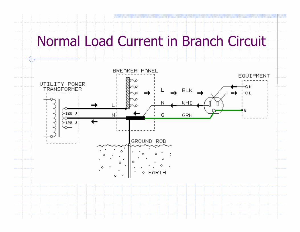
Normal Load Current in Branch Circuit
Deadly EquipmentEquipment can become a shock/electrocution hazard if its internal insulation failsSuch a defect can make the entire device “live” at 120 volts and is called a FAULTWithout a safety ground, these failures can shock or electrocute people or start fires!Signal cables conduct 120 volts – one FAULT can turn an entire system into a shock hazard
Don’t Electrocute System Users!!
Shock and ElectrocutionCURRENT determines severity
Under 1 mA causes just an unpleasant “tingling”About 10 mA causes involuntary muscle contraction and “death grip” or suffocation if through chestOver 50 mA through chest can induce ventricular fibrillation – causing brain death minutes later
Dry skin has high resistance – keeping current low when lightly touching a 120-volt wire Skin moisture, larger contact area, or increased pressure will substantially increase currentAlways respect the dangers of electricity!
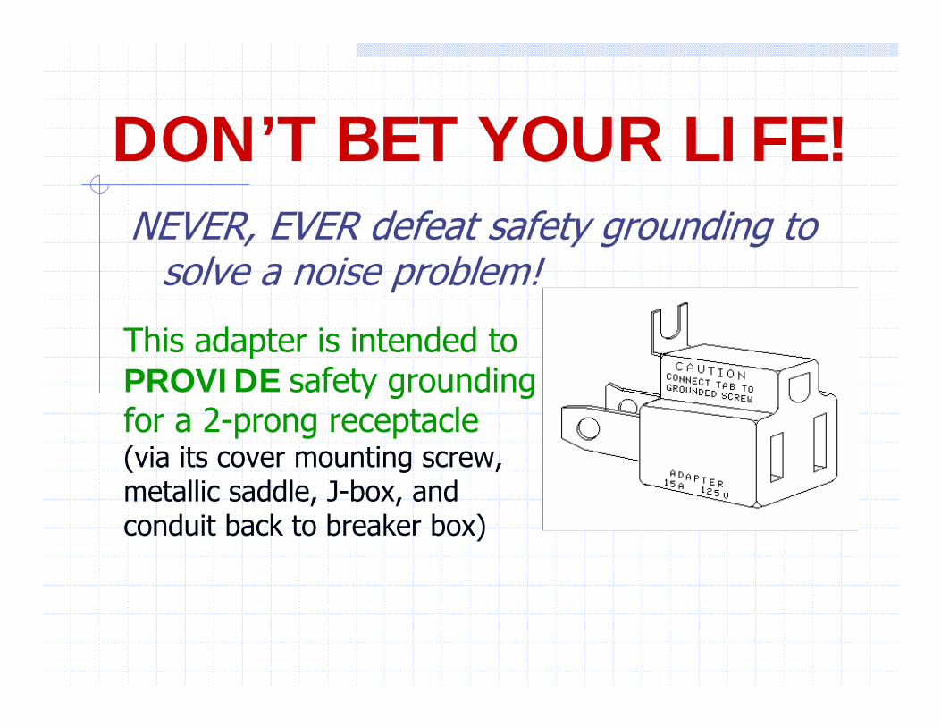
DON’T BET YOUR LIFE!NEVER, EVER defeat safety grounding to
solve a noise problem!
This adapter is intended to PROVIDE safety grounding for a 2-prong receptacle(via its cover mounting screw, metallic saddle, J-box, and conduit back to breaker box)
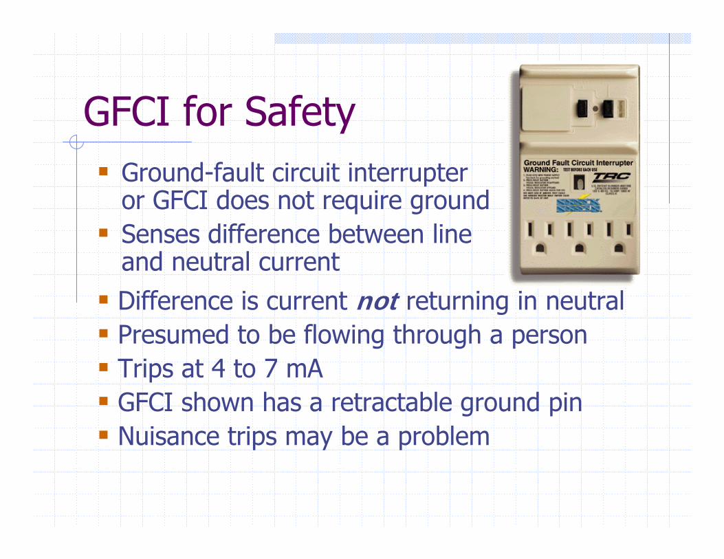
GFCI for SafetyGround-fault circuit interrupter or GFCI does not require groundSenses difference between line and neutral currentDifference is current not returning in neutralPresumed to be flowing through a personTrips at 4 to 7 mAGFCI shown has a retractable ground pinNuisance trips may be a problem
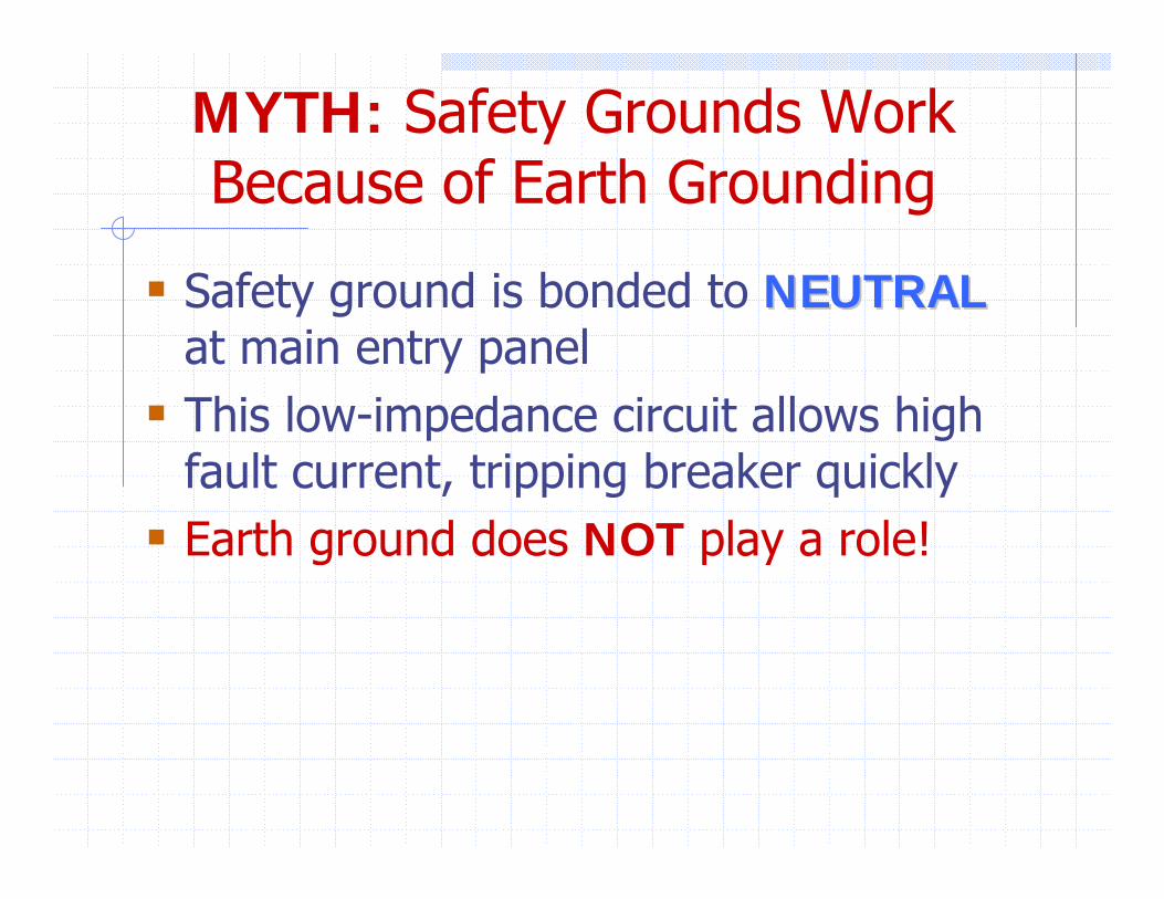
MYTH: Safety Grounds Work Because of Earth Grounding
Safety ground is bonded to NEUTRALNEUTRALat main entry panelThis low-impedance circuit allows high fault current, tripping breaker quicklyEarth ground does NOT play a role!
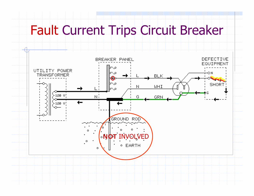
Fault Current Trips Circuit Breaker
NOT INVOLVED
Consider Signal CablesCan distribute lethal voltage from “lifted” faulty device throughout entire system, orHigh fault current may flow through signalcable to reach grounded device, causing fireDefeating safety grounding is both dangerous and illegal — it also makes you legally liable!
Judge won’t care how your “fix” solved problem
Typical Statistics for USAConsumer audio/video equipment causes 10 electrocutions and 2,000 residential fires every yearFires result in 100 civilian injuries, 20 deaths, and over $30 million in property losses
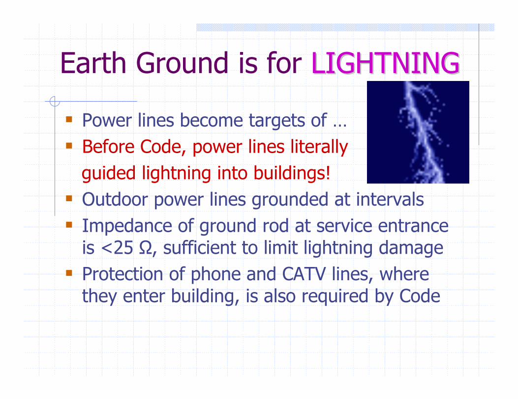
Earth Ground is for LIGHTNINGLIGHTNING
Power lines become targets of …Before Code, power lines literallyguided lightning into buildings!Outdoor power lines grounded at intervalsImpedance of ground rod at service entrance is <25 Ω, sufficient to limit lightning damageProtection of phone and CATV lines, where they enter building, is also required by Code
Bond Added Ground RodsDuring actual strike, thousands of volts can develop between separate rods!
Consider computer modem bridging power and telephone lines
Code requires that all other protective grounds be bonded to the utility power grounding electrode
MYTH: Earth Ground = Zero VoltsNOT with respect to each other or some mystical “absolute” reference pointOther nearby ground connections create soil voltage gradients“Those looking for a better earth or better ground to solve a noise problem are looking for pie in the sky.” Ralph Morrison
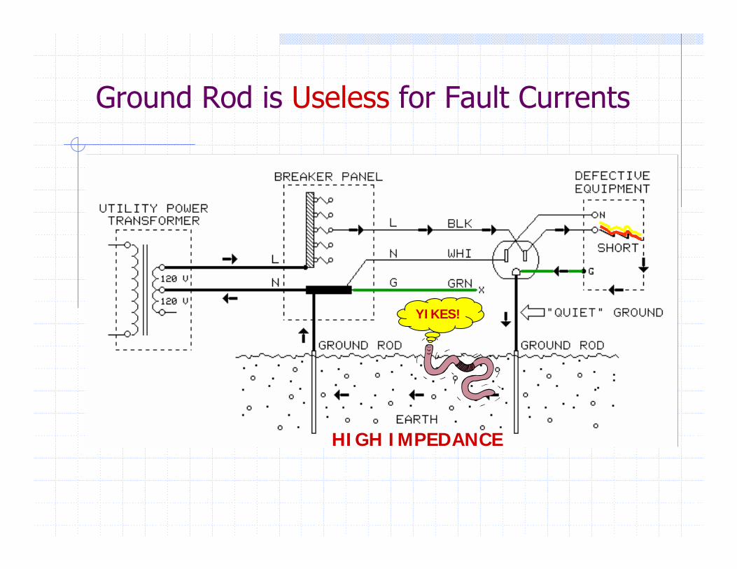
Ground Rod is Useless for Fault Currents
HIGH IMPEDANCE
YIKES!
MYTH: Most Noise is Caused by“Improper” AC Power Wiring
Small voltages between outlet safety grounds is NORMAL in proper wiring
Parasitic transformer effects in wiringLowest between nearby outlets on the samebranch circuitHighest (up to a few volts) between distant outlets on different branch circuits
INTERFACE problems cause the NOISE!
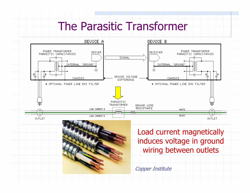
The Parasitic Transformer
Load current magnetically induces voltage in ground
wiring between outlets
Copper Institute
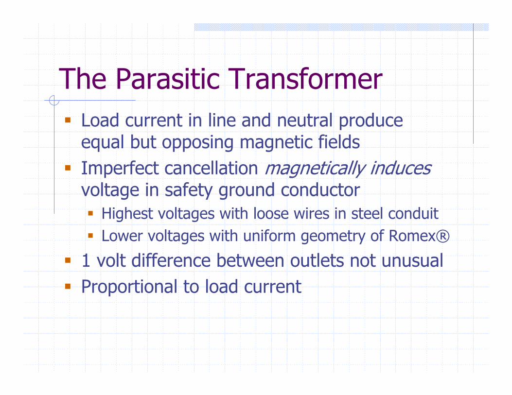
The Parasitic TransformerLoad current in line and neutral produce equal but opposing magnetic fieldsImperfect cancellation magnetically inducesvoltage in safety ground conductor
Highest voltages with loose wires in steel conduitLower voltages with uniform geometry of Romex®
1 volt difference between outlets not unusualProportional to load current
About 2-prong Plugs
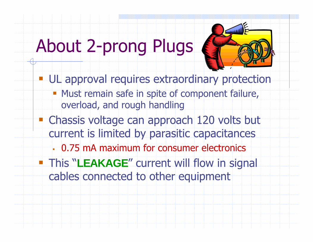
UL approval requires extraordinary protectionMust remain safe in spite of component failure, overload, and rough handling
Chassis voltage can approach 120 volts but current is limited by parasitic capacitances
0.75 mA maximum for consumer electronics
This “LEAKAGE” current will flow in signal cables connected to other equipment
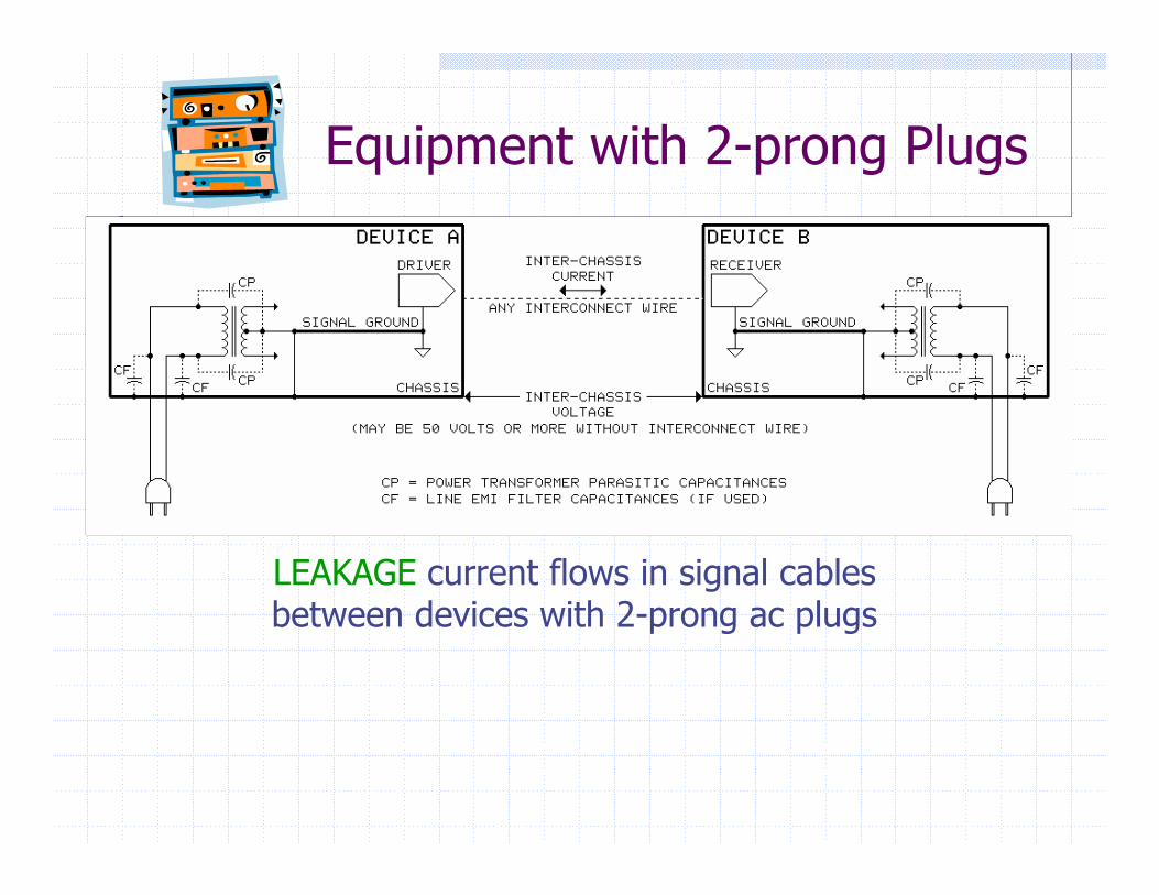
Equipment with 2-prong Plugs
LEAKAGE current flows in signal cables between devices with 2-prong ac plugs
The Facts Of LifeGround voltage differences will ALWAYS exist between outletsLeakage currents will ALWAYS flow in signal cablesCOUPLING allows them to enter the signal path and is the REAL problem!
It’s Not Just 60 HzMany, if not most, loads draw current non-uniformly during each cycleWaveform distortion = 2% to 6% THDHigher frequencies generated by abrupt current changes (as in light dimmers)Power wiring “rings” and reflects energy throughout building
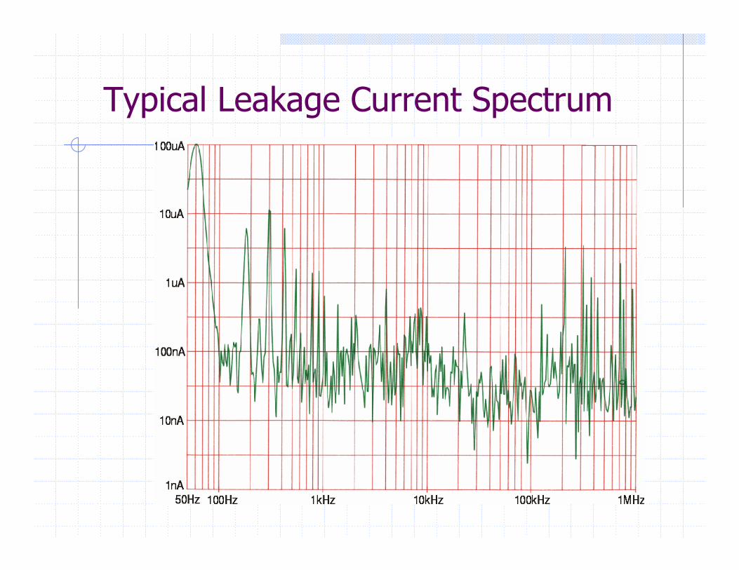
Typical Leakage Current Spectrum
MYTH: These Voltages and Currents can be Eliminated
“SHORT ‘EM OUT” with massive copper bus barsExperiment to find a “better” or “quieter” groundRoute noise to an earth ground where it disappearsMake the electrician fix “his” problemInstall equipment to “purify” the “dirty” ac powerDoes an earth ground really stop noise? Think about all the electronics in a 747 ...
MYTH: Wire “Shorts Out” VoltageDC resistance is directly proportional to length and applies only at low frequencies
0.015 S for 10 feet of #12 AWG example
Inductance is directly proportional to length and nearly independent of its diameter
4.8 :H for example (straight)Increases substantially at bends
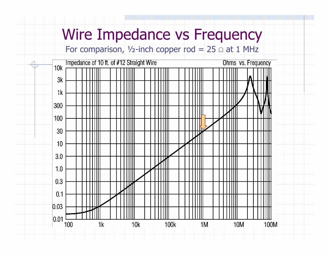
Wire Impedance vs FrequencyFor comparison, ½-inch copper rod = 25 S at 1 MHz
Think “Outside the Box”SIGNALS accumulate NOISE as they flow through a systemRemoving noise without altering/degrading the signal is essentially impossibleEntire signal path must prevent noise couplingSignal INTERFACES are the danger zone, rather than the equipment itself“A cable is a source of potential trouble connecting two other sources of potential trouble.”
What’s an Interface?Signal transport sub-system consisting of a line DRIVER (output), the LINE or cable, and a line RECEIVER (input)TWO conductors are always required to complete a signal (or any) current path

What’s Impedance?The apparent resistance to current flow in an AC circuit – the functional equivalent of resistance in a DC circuitSymbolized Z and measured in ohms
Balanced and UnbalancedStatus depends ONLY on the IMPEDANCES(to ground) of the two signal conductorsIn unbalanced interface, one line has zeroimpedance (grounded) and other has some higher impedanceIn balanced interface, both have nominally equal impedances
Requires that driver, line, and receiver eachmaintain equal impedances
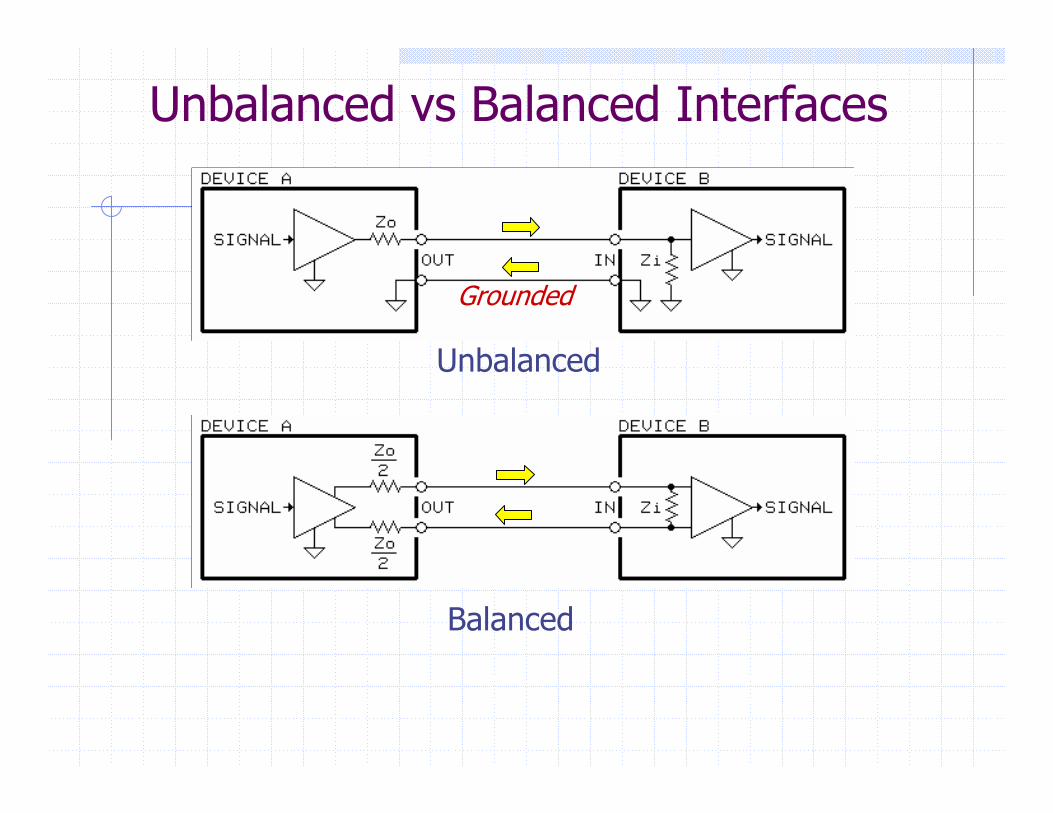
Unbalanced
Balanced
Unbalanced vs Balanced Interfaces
Grounded
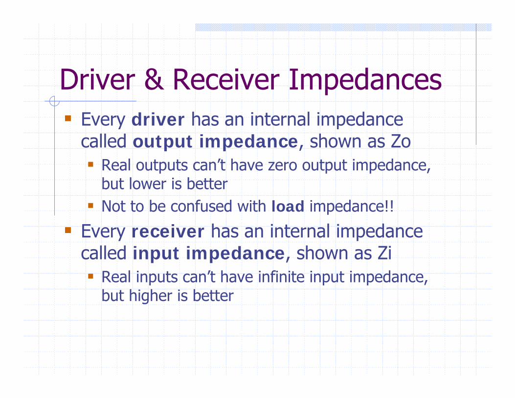
Driver & Receiver ImpedancesEvery driver has an internal impedance called output impedance, shown as Zo
Real outputs can’t have zero output impedance, but lower is betterNot to be confused with load impedance!!
Every receiver has an internal impedance called input impedance, shown as Zi
Real inputs can’t have infinite input impedance, but higher is better
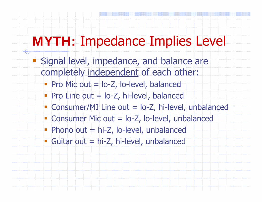
MYTH: Impedance Implies LevelSignal level, impedance, and balance are completely independent of each other:
Pro Mic out = lo-Z, lo-level, balancedPro Line out = lo-Z, hi-level, balancedConsumer/MI Line out = lo-Z, hi-level, unbalancedConsumer Mic out = lo-Z, lo-level, unbalancedPhono out = hi-Z, lo-level, unbalancedGuitar out = hi-Z, hi-level, unbalanced
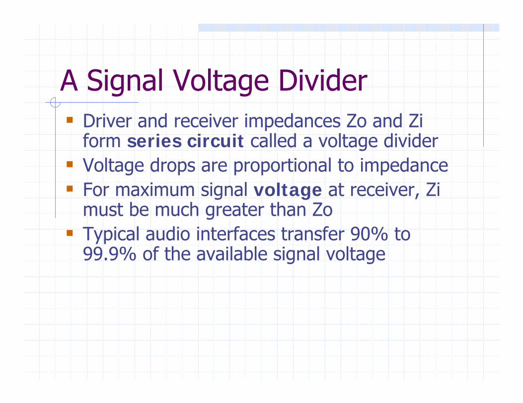
A Signal Voltage DividerDriver and receiver impedances Zo and Ziform series circuit called a voltage dividerVoltage drops are proportional to impedanceFor maximum signal voltage at receiver, Zimust be much greater than ZoTypical audio interfaces transfer 90% to 99.9% of the available signal voltage

Unbalanced
Balanced
The Signal Voltage Divider
Grounded
MYTH: Audio Inputs and OutputsShould Be “Impedance Matched”
Wastes half the signal voltage and places an unnecessarily heavy load on the driver!Transfers maximum power in vintage passive 600 Ω systems but not applicable to modern audio systems driven by signal voltageHigher frequency cables are terminated with the “characteristic impedance” of the cable to avoid “transmission line” effects
Characteristic impedance is that of an infinite length of cable and varies with construction
Termination for Video and RF“Transmission line” effects start to become significant when the physical length of a cable becomes ~10% of an electrical wavelengthApplies to video cables over a few feet long and CATV cables over a few inches longTo avoid video “ghosts,” source and load impedances at physical ends must match the characteristic impedance of the cableFor audio cables, termination is a concern only when cables are over 4,000 feet long!
UNBALANCED InterfacesEXTREMELY susceptible to noise coupling!Ironic that, after 50 years, they remain the norm in consumer and audiophile audio, even as dynamic range requirements have steadily increasedVideo interfaces (analog)
Coupling causes visible “hum bars”
RS-232 interfacesCoupling causes “mysterious” problems
The Big ProblemLeakage currents flow in signal cables
Virtually all in grounded conductor, typically the “shield,” whose impedance is not zero
Noise voltage generated over its length due to its resistance – Ohm’s LawNoise directly adds to signal seen at receiver (voltages add in series circuit)
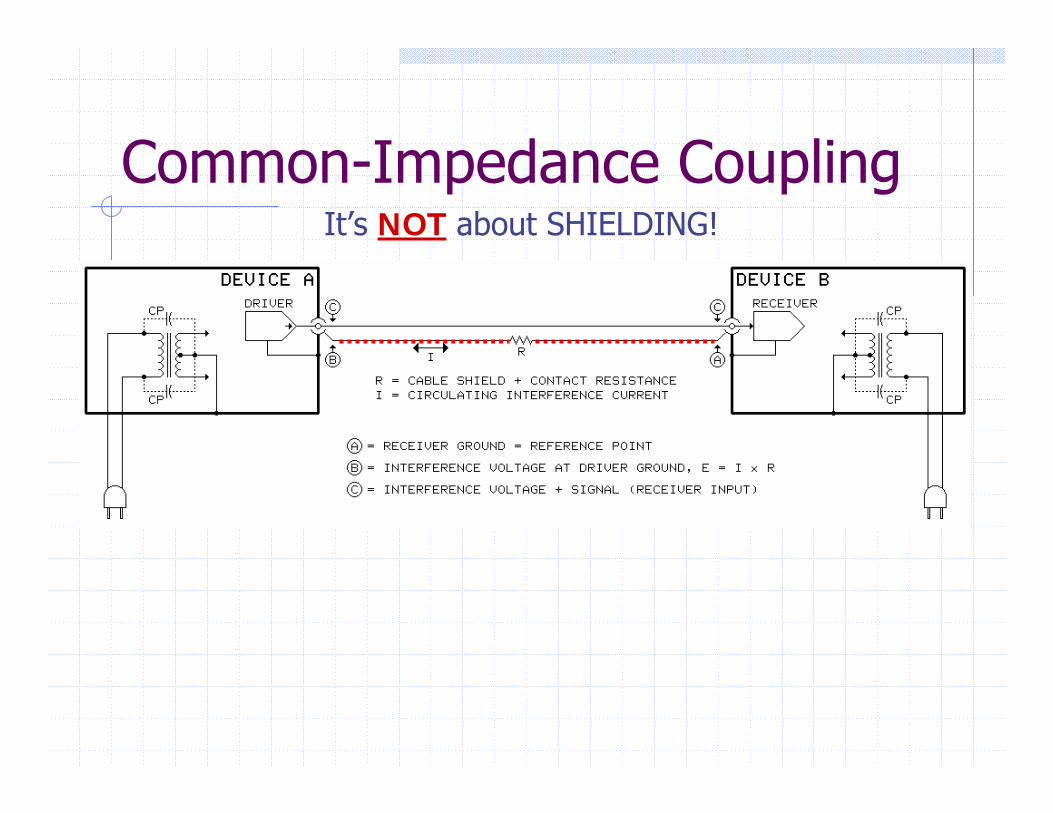
Common-Impedance CouplingIt’s NOT about SHIELDING!
MYTH: Poor Shielding Causes Noise
Common-impedance coupling causes 99% of noise problems in unbalanced interfacesTrivial noise contributor in modern systemsAudiophile cables from famous maker, costing $80 to $500 per 1-meter pair, have no shield at all — wires are simply woven together!Shielding can be issue with old vacuum-tube equipment because of high Zo in drivers
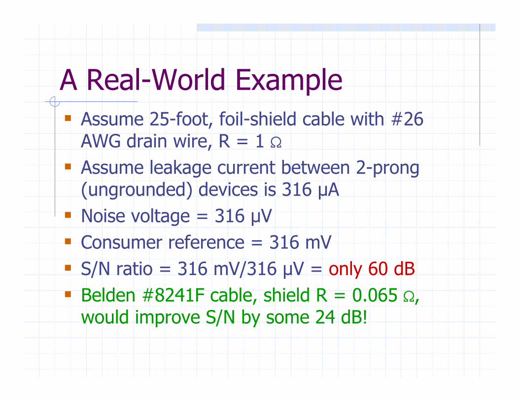
A Real-World ExampleAssume 25-foot, foil-shield cable with #26 AWG drain wire, R = 1 SAssume leakage current between 2-prong (ungrounded) devices is 316 µANoise voltage = 316 µV Consumer reference = 316 mVS/N ratio = 316 mV/316 µV = only 60 dBBelden #8241F cable, shield R = 0.065 S, would improve S/N by some 24 dB!
From Bad to Worse …When devices are grounded, often via other system cables, noise can become EXTREME!
When ground voltage difference of only 30 mV between outlets is impressed across length of cable, resulting S/N becomes only 20 dBHuge problem in home theater systems having multiple ground connections – sub-woofers and projectors with 3-prong plugs, CATV, and satellite TV connections
Cable ShieldingShields prevent ONLY electric field couplingElectric fields produced by high ac voltagesCapacitance Cc in space to offending sourceAC voltage causes current flow in CcWithout shield, current flows into signal line, creating a noise voltageGrounded shield diverts currents to ground
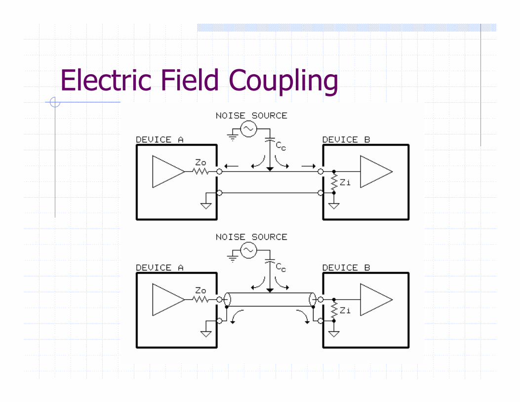
Electric Field Coupling
Shield “Coverage”Foil is usually 100% (optically opaque)Braided from 85% to 95% because of tiny openings — usually entirely adequateProblem only for very high-impedance line drivers – typical of some vacuum-tube gearTrivial issue in the vast majority of systems
Well-known maker offers several lines of cables, priced from $80 to $500 per 1-meter pair, which have no overall shield — wires are simply woven
Immunity to Magnetic FieldsRegardless of cable construction, unbalanced interfaces can’t fully nullify the effectsEffective magnetic shielding, especially at power frequencies, is very difficult to achieveOnly magnetic materials like steel conduit provide any significant shielding — ordinary cable shielding has no effect
More about this later (balanced interfaces)
Physics from Another Universe?Audio, especially "high-end," abounds with pseudo-science and mysticismDouble-blind tests prove that audible differences among cables, if they actually exist, are entirely predictableMarketing hype* often invokes transmission line theory and implies that nano-second pulse rise-times are important
Audio cables only begin to exhibit such effects when they become about 4,000 feet long!
* Hype: enthusiasm without knowledge
MYTH: Exotic Cables Stop Noise
Expensive cables, even if double or triple shielded, made of 100% unobtainium, and hand woven by virgins will have nosignificant effect on hum or buzz ……
Only the resistance of the grounded conductor can make a difference!
Real Unbalanced Cable IssuesResistance of grounded conductor
99% of problems are common-impedance coupling
CapacitanceAffects signal bandwidth for long lengths
ShieldingAffects only LF electric fields and RF
Magnetic field immunityProvided by coaxial or twisted construction
Troubleshooting
Troubleshooting without method can be very frustrating and time-consumingDon’t start by changing things!Ask questions – “Did it ever work right?”Equipment controls provide valuable cluesKeep written notes, memory is less reliableProblems that go away by themselves also tend to come back by themselves
Draw a “One-Liner”Show all signal cables, including digital and RF, and indicate their approximate lengthMark any balanced inputs or outputs Generally, show stereo pairs as a single lineNote equipment grounded by its 3-prong power plugNote any other ground connections such as cable TV or DSS dishes
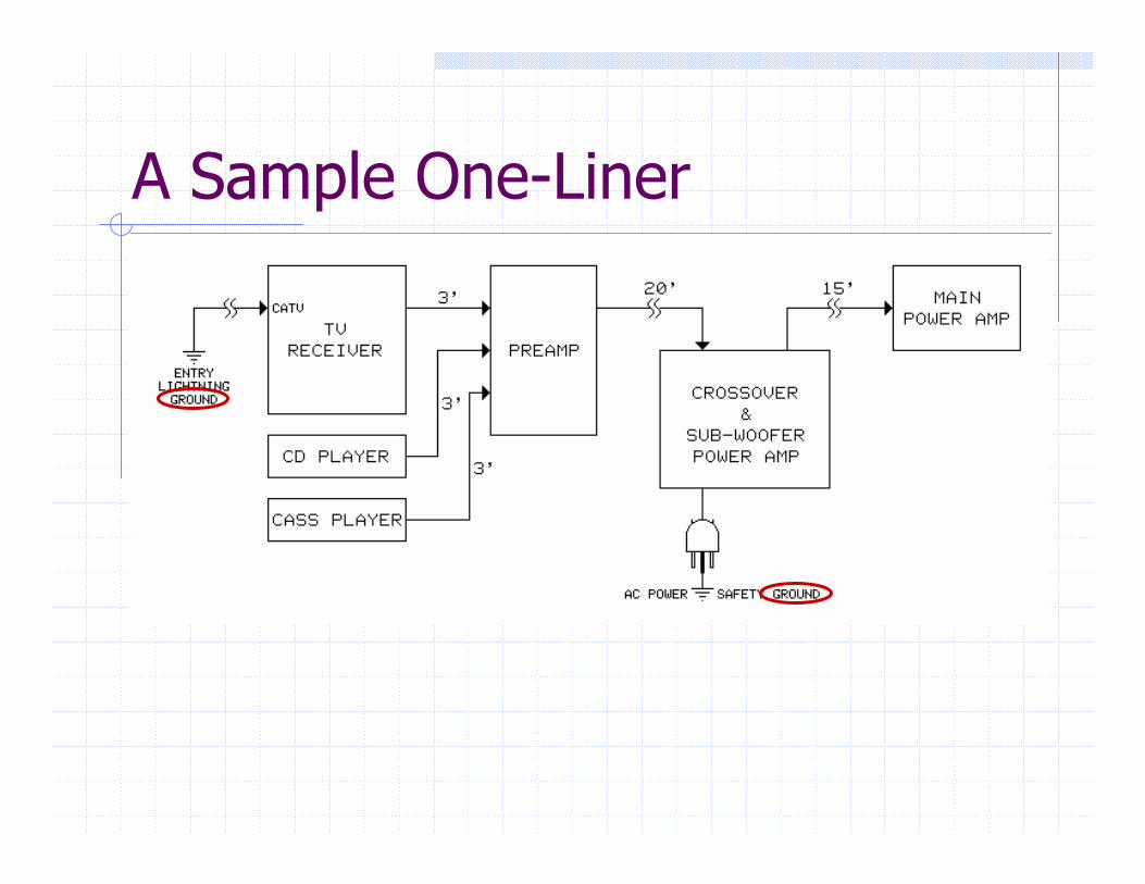
A Sample One-Liner
Work BackwardsUnless clues suggest otherwise, always begin at audio power amplifier inputs or video monitor inputs and test interfaces sequentially back toward signal sourcesRemove any ground “lift” devices before you begin troubleshooting!
Testing Audio Interfaces“Dummies” can locate noise coupling pointAlso reveal the nature of the problem:
Common-impedance coupling - unbalanced cablesShield-current-induced coupling - balanced cablesMagnetic or electric field coupling in cables“Pin 1 problems” in defective equipment
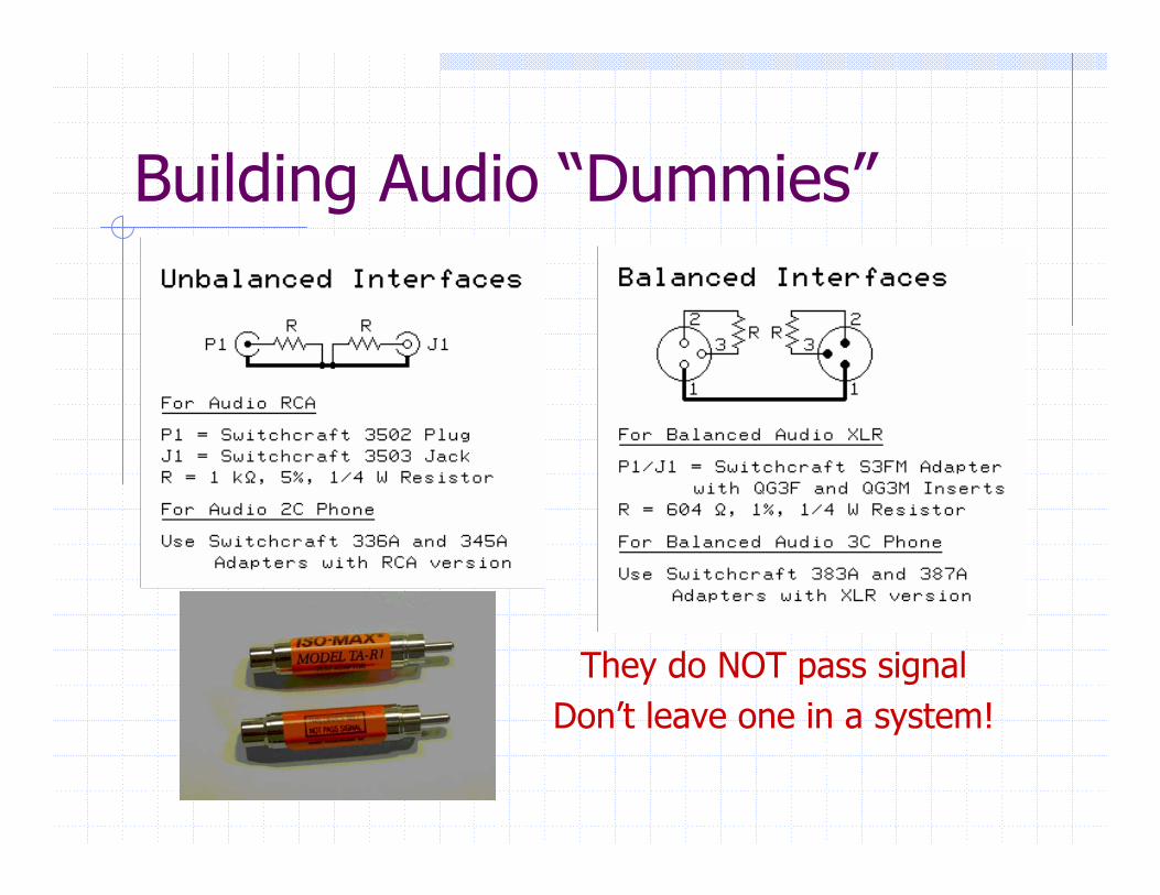
Building Audio “Dummies”
They do NOT pass signalDon’t leave one in a system!
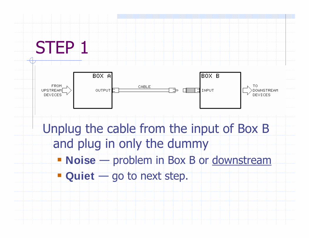
STEP 1
Unplug the cable from the input of Box B and plug in only the dummy
Noise — problem in Box B or downstreamQuiet — go to next step.
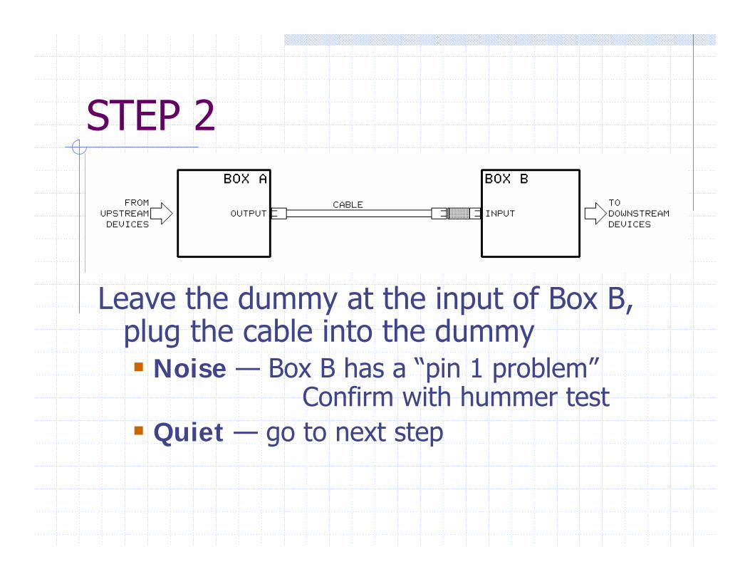
STEP 2
Leave the dummy at the input of Box B, plug the cable into the dummy
Noise — Box B has a “pin 1 problem” Confirm with hummer test
Quiet — go to next step
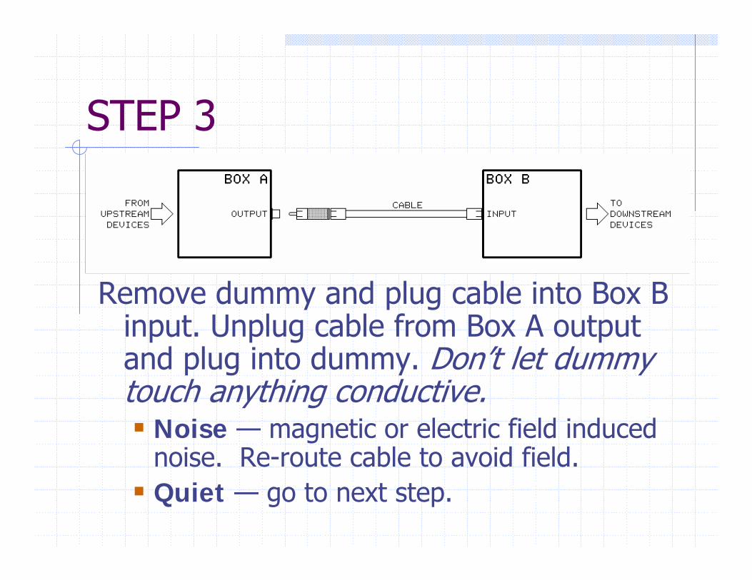
STEP 3
Remove dummy and plug cable into Box B input. Unplug cable from Box A output and plug into dummy. Don’t let dummy touch anything conductive.
Noise — magnetic or electric field induced noise. Re-route cable to avoid field.Quiet — go to next step.
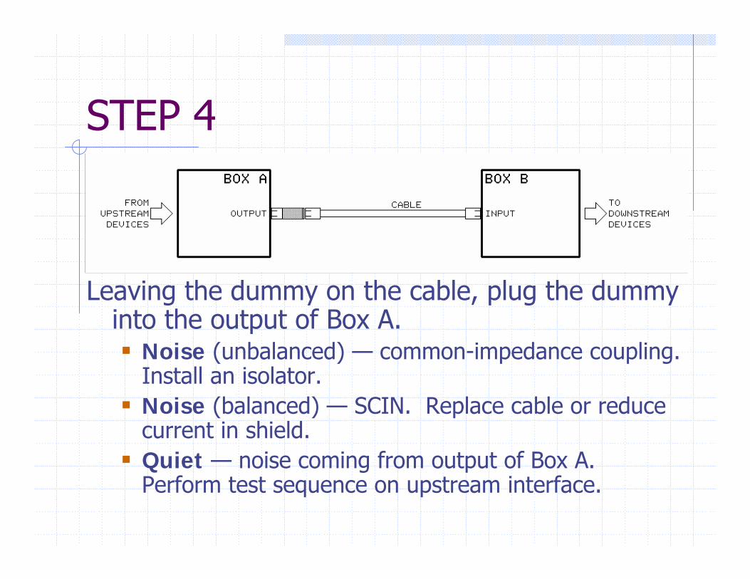
STEP 4
Leaving the dummy on the cable, plug the dummy into the output of Box A.
Noise (unbalanced) — common-impedance coupling. Install an isolator.Noise (balanced) — SCIN. Replace cable or reduce current in shield.Quiet — noise coming from output of Box A. Perform test sequence on upstream interface.
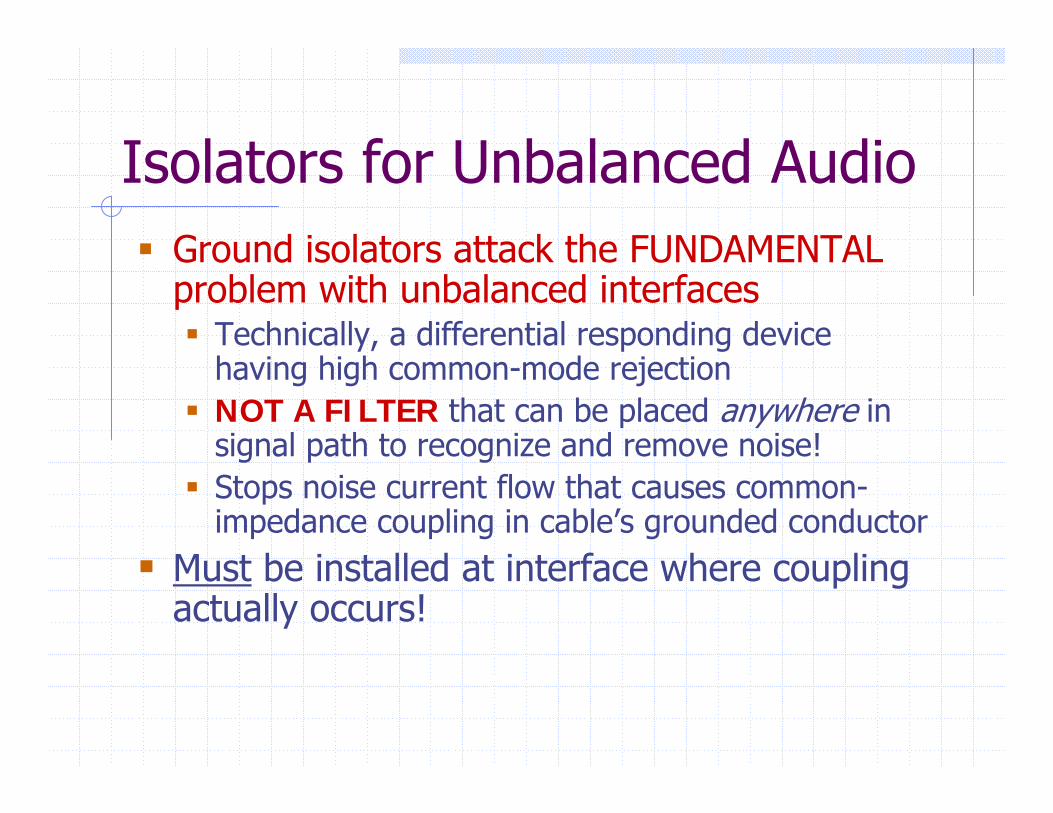
Isolators for Unbalanced AudioGround isolators attack the FUNDAMENTAL problem with unbalanced interfaces
Technically, a differential responding device having high common-mode rejectionNOT A FILTER that can be placed anywhere in signal path to recognize and remove noise!Stops noise current flow that causes common-impedance coupling in cable’s grounded conductor
Must be installed at interface where coupling actually occurs!
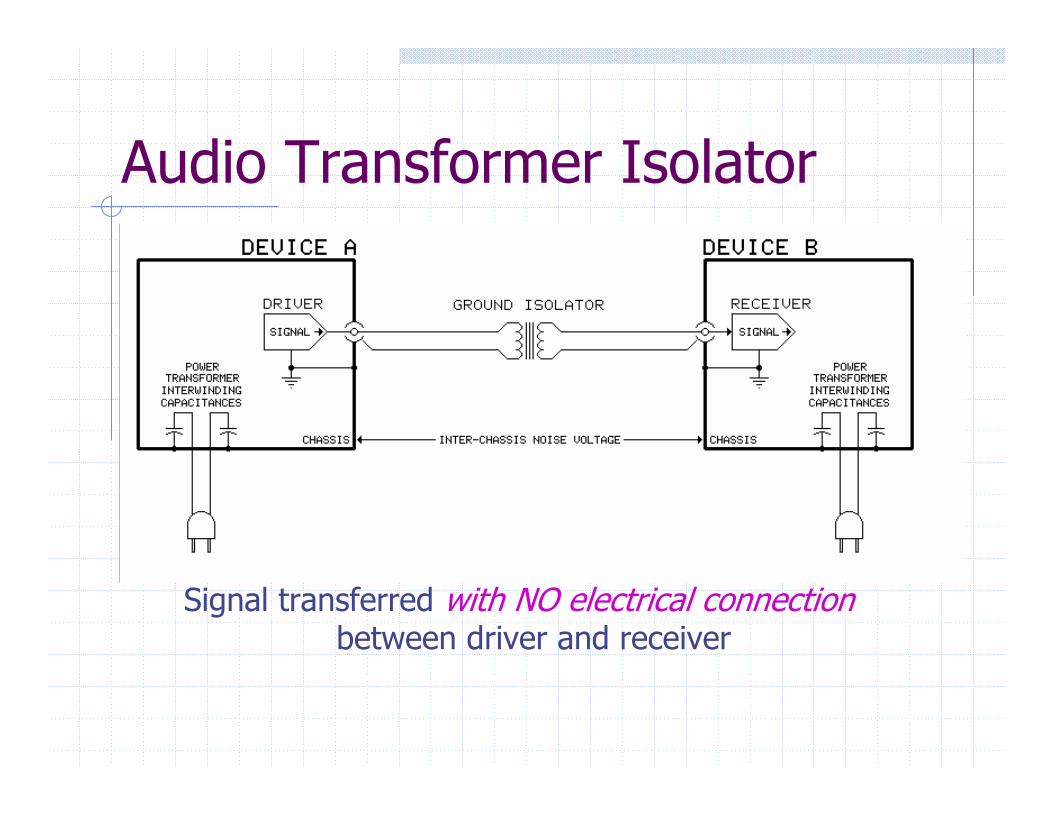
Audio Transformer Isolator
Signal transferred with NO electrical connectionbetween driver and receiver
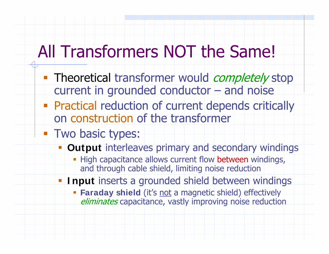
All Transformers NOT the Same!Theoretical transformer would completely stop current in grounded conductor – and noisePractical reduction of current depends critically on construction of the transformerTwo basic types:
Output interleaves primary and secondary windingsHigh capacitance allows current flow between windings, and through cable shield, limiting noise reduction
Input inserts a grounded shield between windingsFaraday shield (it’s not a magnetic shield) effectively eliminates capacitance, vastly improving noise reduction
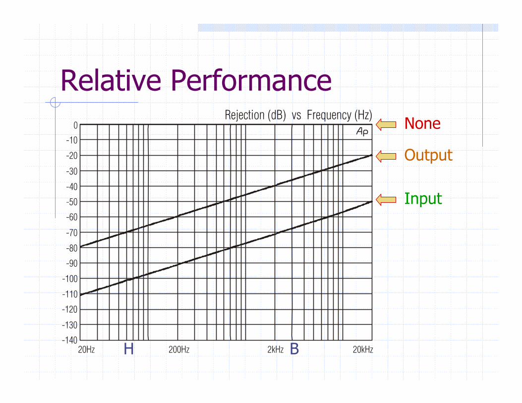
Relative PerformanceNone
Output
Input
H B
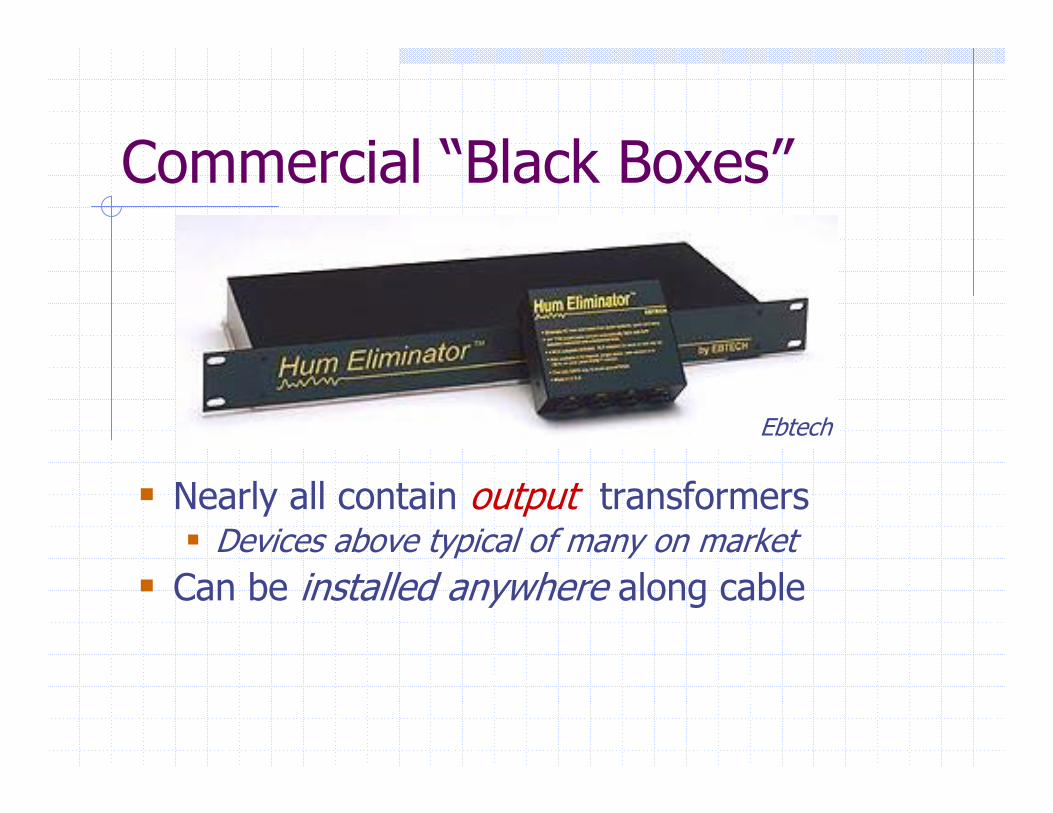
Commercial “Black Boxes”
Nearly all contain output transformersDevices above typical of many on market
Can be installed anywhere along cable
Ebtech
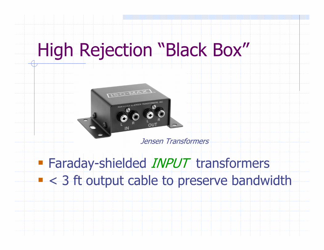
High Rejection “Black Box”
Faraday-shielded INPUT transformers< 3 ft output cable to preserve bandwidth
Jensen Transformers
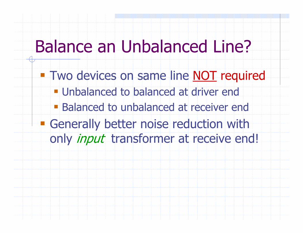
Balance an Unbalanced Line?
Two devices on same line NOT requiredUnbalanced to balanced at driver endBalanced to unbalanced at receiver end
Generally better noise reduction with only input transformer at receive end!
Signal Quality Issues
Check isolator performance carefullySpecs often vague or non-existentSome contain $2 “telecom” transformers
Loss of deep bassBass distortionPoor transient response
Specs of quality products are complete, unambiguous, and verifiable
Transformer BenefitsInput-transformer-based isolators
Make inputs truly universal – accept signals from either balanced or unbalanced outputs while maintaining >80 dB noise rejectionInherently suppress RF and ultrasonic interference, reducing “spectral contamination”
ALL transformer-based isolatorsPassive – require no powerRobust, reliable, and virtually immune to transient over-voltages
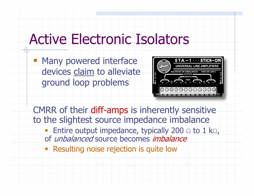
Active Electronic IsolatorsMany powered interface devices claim to alleviate ground loop problems
CMRR of their diff-amps is inherently sensitive to the slightest source impedance imbalance
Entire output impedance, typically 200 S to 1 kS,of unbalanced source becomes imbalance
Resulting noise rejection is quite low
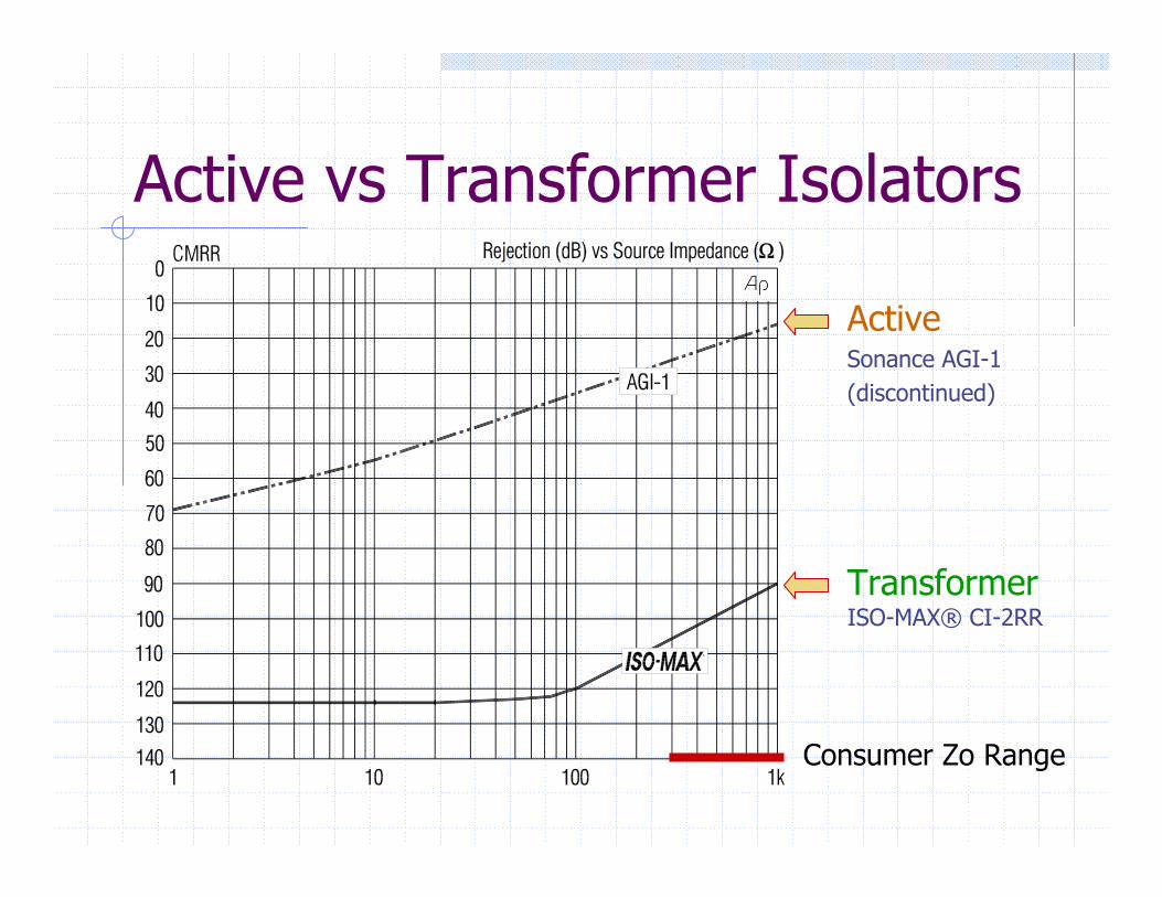
Active vs Transformer Isolators
ActiveSonance AGI-1(discontinued)
TransformerISO-MAX® CI-2RR
Consumer Zo Range
Break the Loop Where?
Ground loop may include many cablesCoupling usually proportional to lengthNever defeat safety grounding!Install a ground isolator in signal pathChoice may be cost drivenIn example, either at receive end of long audio cable or a CATV isolator
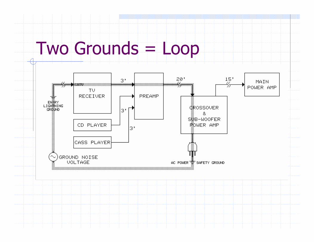
Two Grounds = Loop
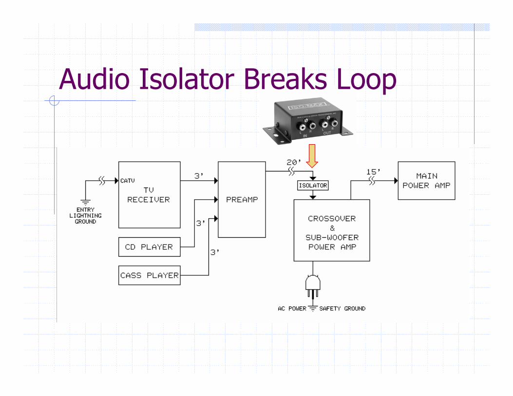
Audio Isolator Breaks Loop
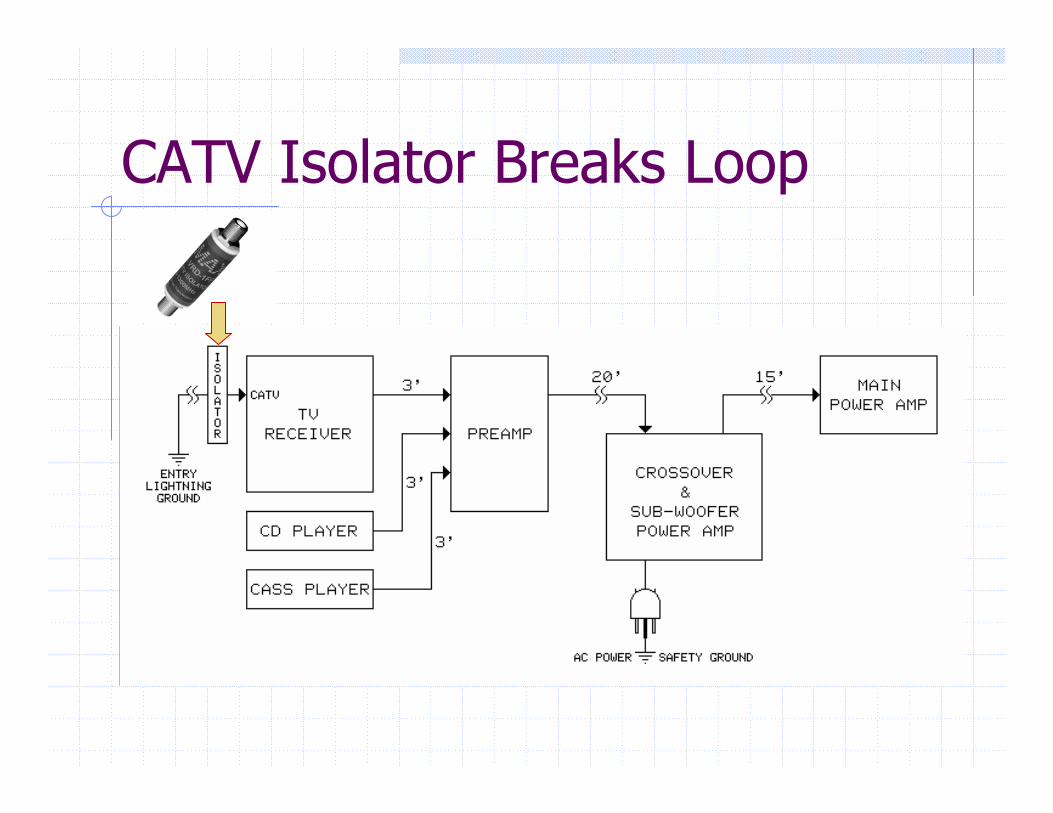
CATV Isolator Breaks Loop
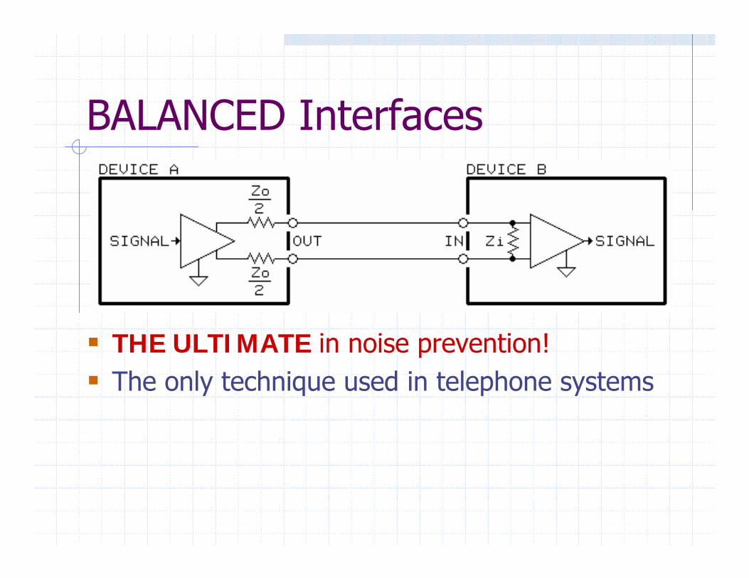
BALANCED Interfaces
THE ULTIMATE in noise prevention!The only technique used in telephone systems
MYTH: Balance = Signal SymmetryExample from “white paper” at well-known manufacturer’s website:
“Each conductor is always equal in voltage but opposite in polarity to the other. The circuit that receives this signal in the mixer is called a differential amplifier and this opposing polarity of the conductors is essential for its operation.” Not only WRONG but it misses the truly essential feature of a balanced interface
The Real Definition“A balanced circuit is a two-conductor circuit in
which both conductors and all circuits connected to them have the same impedance with respect to ground and to all other conductors. The purpose of balancing is to make the noise pickup equal in both conductors, in which case it will be a common-mode signal which can be made to cancel out in the load.” - Henry Ott
Furthermore …“Only the common-mode impedance balance of the
driver, line, and receiver play a role in noise or interference rejection. This noise or interference rejection property is independent of the presence of a desired differential signal. Therefore, it can make no difference whether the desired signal exists entirely on one line, as a greater voltage on one line than the other, or as equal voltages on both of them. Symmetry of the desired signal has advantages, but they concern headroom and crosstalk, not noise or interference rejection.”
from “Informative Annex” of IEC Standard 60268-3
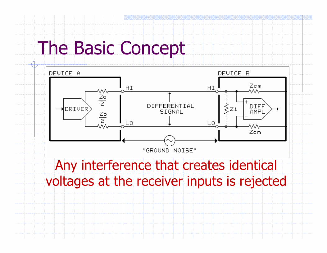
The Basic Concept
Any interference that creates identical voltages at the receiver inputs is rejected
The History of Balanced LinesBell Telephone pioneered useEarly systems passive – no amplifiers Miles of existing telegraph lines usedWire size & spacing set 600 Ω standardTransformers & filters made for 600 ΩEquipment migrated to radio & recording
The “600 Ω legend” just won’t go away!
Where Did We Go Wrong?TRANSFORMERS were essential elements of EVERY balanced interface 50 years ago …High noise rejection was taken for granted but very few engineers understood why it worked Differential amplifiers, cheap and simple, began replacing audio transformers by 1970Equipment specs promised high CMRR, but noise problems in real-world systems became more widespread than ever before …
Reputation of balanced interfaces began to tarnish and “pin 1” problems also started to appear!
Common Mode? Normal Mode?
Voltages, to ground, that are equal at both inputs are called common-mode
Voltage between driver & receiver groundsVoltage induced in cable by magnetic fieldsVoltage induced in cable by electric fields
Voltages between the inputs are called “differential” or normal-mode (signal)
Common-mode Rejection IDEAL receiver responds only to normal-mode, with no response to common-mode … it would have infinite Common-Mode RejectionRejection is limited in real-world receiversRatio, in dB, of differential to common-mode gain is Common-Mode Rejection Ratio, CMRRNoise rejection of the entire interface (what really matters) is highly dependent on how the line and driver affect the receiver!
The Wheatstone BridgeDriver and receiver common-mode impedances form a classic Wheatstone bridgeBridge imbalances cause conversion of common-mode noise into normal-mode signalBalance depends critically on matching ratios of common-mode impedances of the lines
Most sensitive to component tolerances when driver and receiver arms have same impedancesLeast sensitive when driver and receiver arms have widely differing impedances
Receiver arm impedances should be very high!
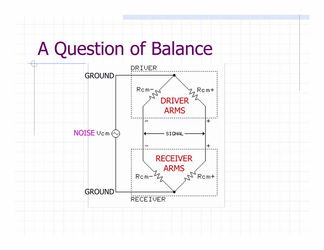
A Question of Balance
DRIVERARMS
RECEIVERARMS
GROUND
GROUND
NOISE
Blinded by Bad ScienceCMRR traditionally measured with a perfectsource … Good marketing but bad science!Impedance imbalance at outputs of real audio gear can be ±30 Ω or moreIEC recognized inadequacy of their existing CMRR test in 1998 and invited commentsWhitlock suggested a new procedure that was adopted in August, 2000 as IEC 60268-3
Inserts 10 Ω imbalances, first in one leg and then in the other, of the test signal generator
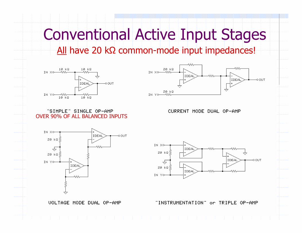
Conventional Active Input StagesAll have 20 kΩ common-mode input impedances!
OVER 90% OF ALL BALANCED INPUTS
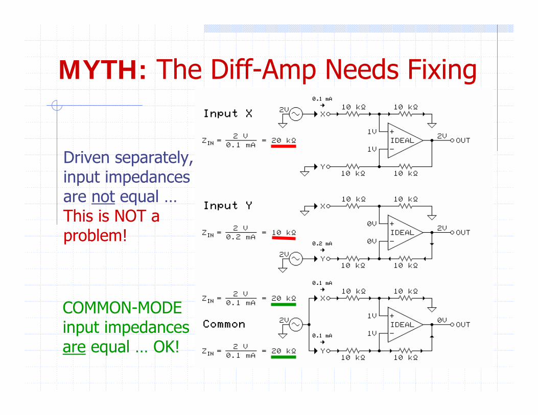
MYTH: The Diff-Amp Needs Fixing
Driven separately,input impedancesare not equal … This is NOT a problem!
COMMON-MODEinput impedancesare equal … OK!
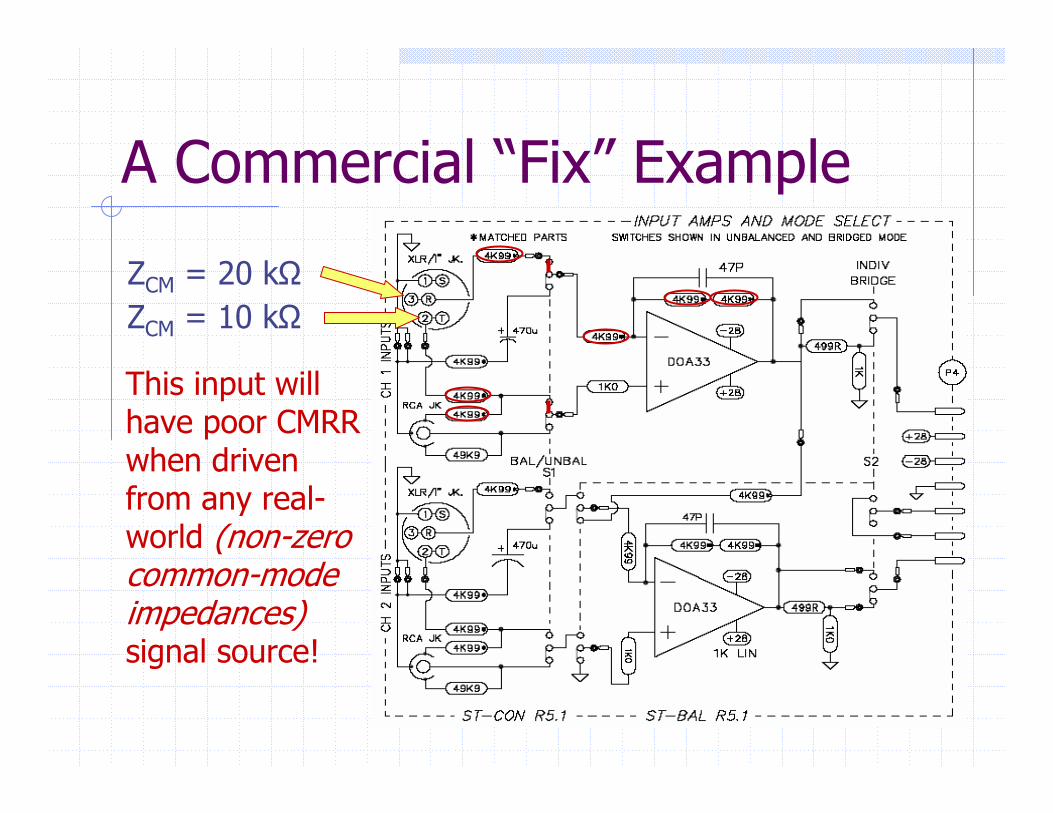
A Commercial “Fix” Example
ZCM = 20 kΩZCM = 10 kΩ
This input will have poor CMRR when driven from any real-world (non-zero common-mode impedances) signal source!
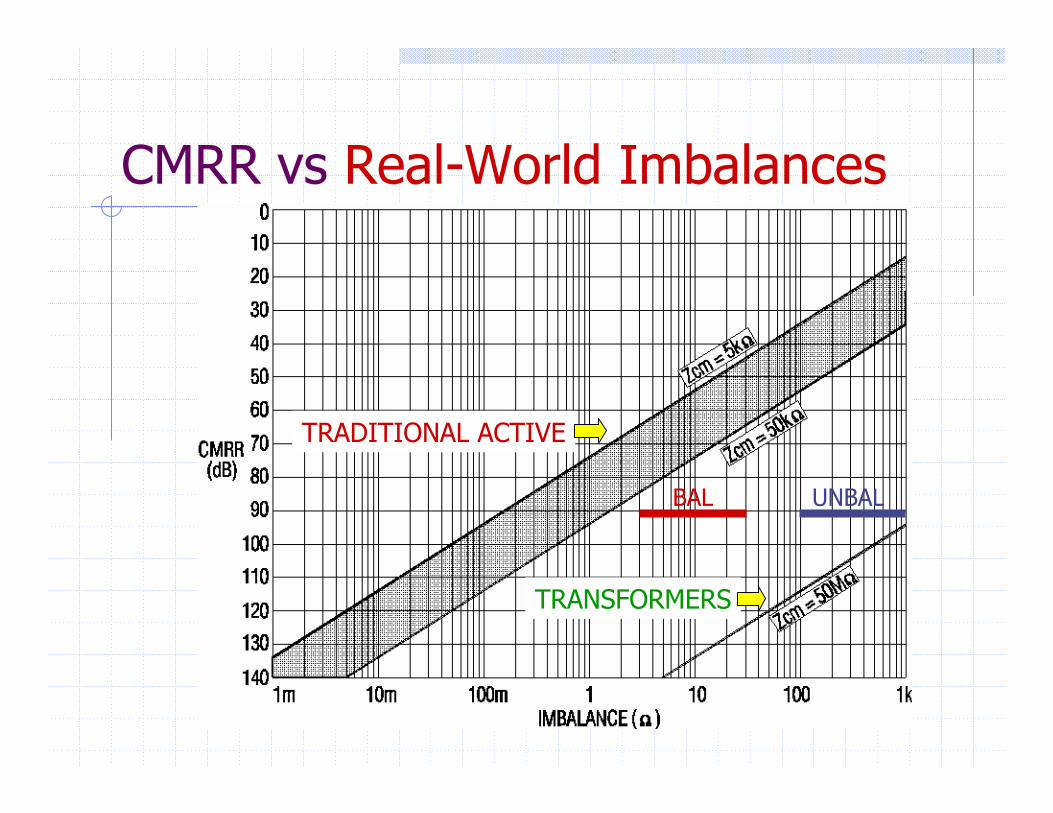
CMRR vs Real-World Imbalances
TRADITIONAL ACTIVE
TRANSFORMERS
BAL UNBAL
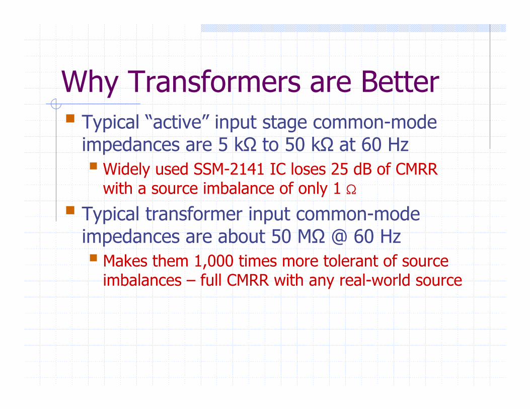
Why Transformers are BetterTypical “active” input stage common-mode impedances are 5 kΩ to 50 kΩ at 60 Hz
Widely used SSM-2141 IC loses 25 dB of CMRR with a source imbalance of only 1 S
Typical transformer input common-mode impedances are about 50 MΩ @ 60 Hz
Makes them 1,000 times more tolerant of source imbalances – full CMRR with any real-world source
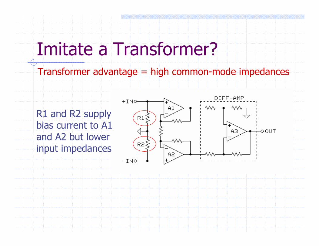
Imitate a Transformer?Transformer advantage = high common-mode impedances
R1 and R2 supply bias current to A1 and A2 but lower input impedances
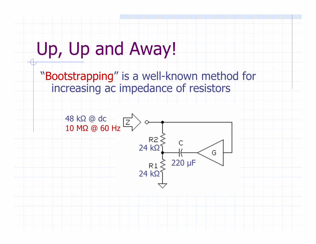
Up, Up and Away!“Bootstrapping” is a well-known method for
increasing ac impedance of resistors
24 kΩ
24 kΩ
220 µF
48 kΩ @ dc10 MΩ @ 60 Hz
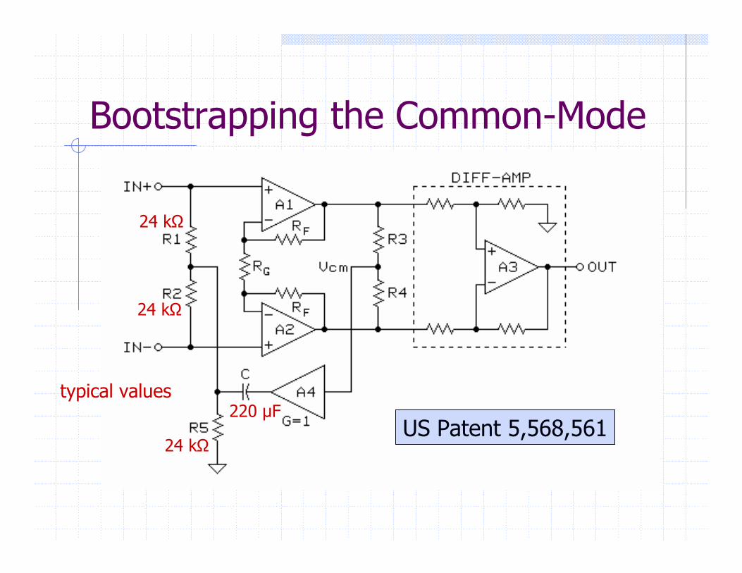
Bootstrapping the Common-Mode
US Patent 5,568,561
24 kΩ
24 kΩ
24 kΩ
220 µFtypical values
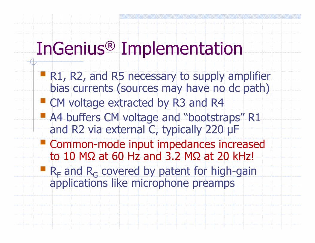
InGenius® ImplementationR1, R2, and R5 necessary to supply amplifier bias currents (sources may have no dc path)CM voltage extracted by R3 and R4A4 buffers CM voltage and “bootstraps” R1 and R2 via external C, typically 220 µFCommon-mode input impedances increased to 10 MΩ at 60 Hz and 3.2 MΩ at 20 kHz!RF and RG covered by patent for high-gain applications like microphone preamps
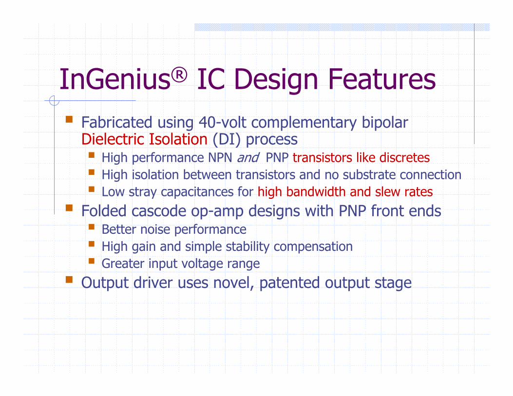
InGenius® IC Design FeaturesFabricated using 40-volt complementary bipolar Dielectric Isolation (DI) process
High performance NPN and PNP transistors like discretesHigh isolation between transistors and no substrate connectionLow stray capacitances for high bandwidth and slew rates
Folded cascode op-amp designs with PNP front endsBetter noise performanceHigh gain and simple stability compensationGreater input voltage range
Output driver uses novel, patented output stage
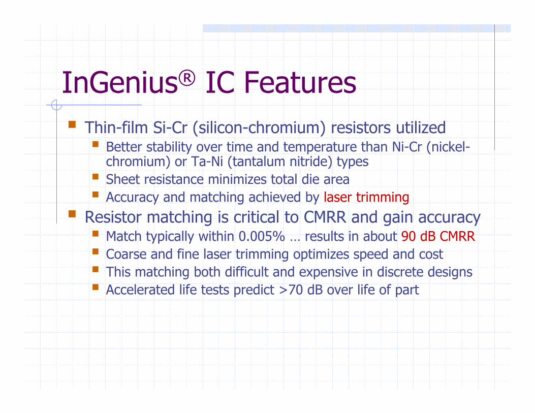
InGenius® IC FeaturesThin-film Si-Cr (silicon-chromium) resistors utilized
Better stability over time and temperature than Ni-Cr (nickel-chromium) or Ta-Ni (tantalum nitride) typesSheet resistance minimizes total die areaAccuracy and matching achieved by laser trimming
Resistor matching is critical to CMRR and gain accuracyMatch typically within 0.005% … results in about 90 dB CMRRCoarse and fine laser trimming optimizes speed and costThis matching both difficult and expensive in discrete designsAccelerated life tests predict >70 dB over life of part

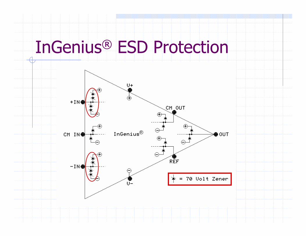
InGenius® IC FabricationThin-film resistors vulnerable to electrostatic discharge (ESD) damage
Input pins must accept input voltages greater than supply rails, posing an ESD protection challengeNew “lateral” protection diode, with typical breakdown of 70 volts, was designed to utilize existing diffusion and implant sequences
All other pins are protected by conventional clamp diodes to supply rails
InGenius® ESD Protection
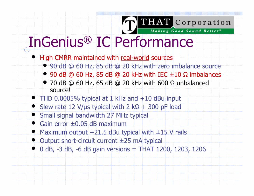
InGenius® IC Performance• High CMRR maintained with real-world sources
• 90 dB @ 60 Hz, 85 dB @ 20 kHz with zero imbalance source• 90 dB @ 60 Hz, 85 dB @ 20 kHz with IEC ±10 Ω imbalances• 70 dB @ 60 Hz, 65 dB @ 20 kHz with 600 Ω unbalanced
source!• THD 0.0005% typical at 1 kHz and +10 dBu input• Slew rate 12 V/µs typical with 2 kΩ + 300 pF load• Small signal bandwidth 27 MHz typical• Gain error ±0.05 dB maximum• Maximum output +21.5 dBu typical with ±15 V rails• Output short-circuit current ±25 mA typical• 0 dB, -3 dB, -6 dB gain versions = THAT 1200, 1203, 1206
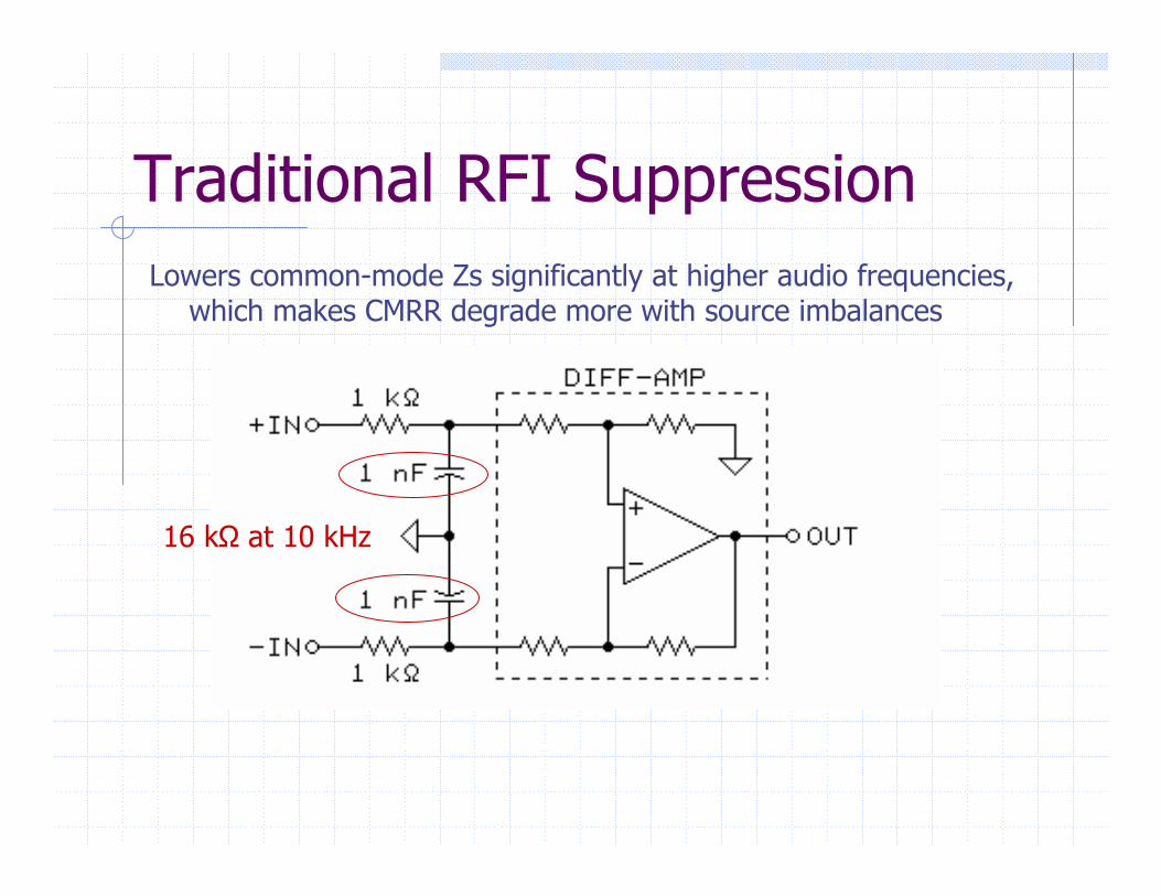
Traditional RFI SuppressionLowers common-mode Zs significantly at higher audio frequencies,
which makes CMRR degrade more with source imbalances
16 kΩ at 10 kHz
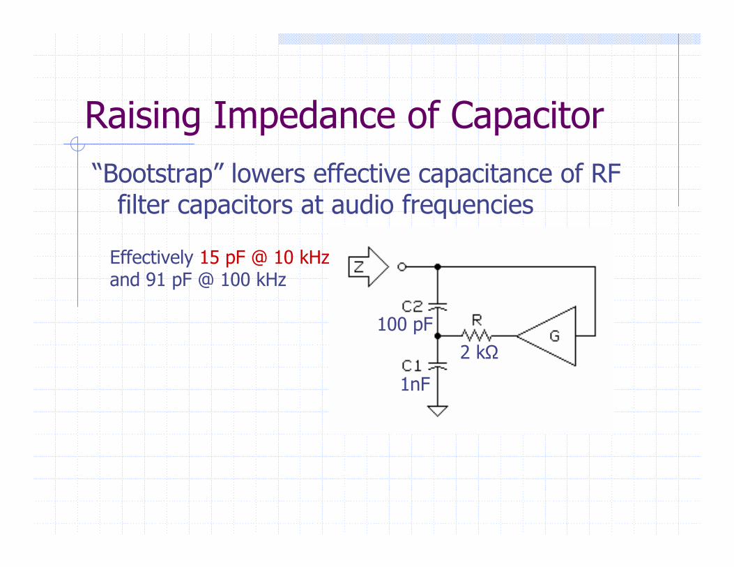
Raising Impedance of Capacitor“Bootstrap” lowers effective capacitance of RF
filter capacitors at audio frequencies
2 kΩ100 pF
1nF
Effectively 15 pF @ 10 kHzand 91 pF @ 100 kHz
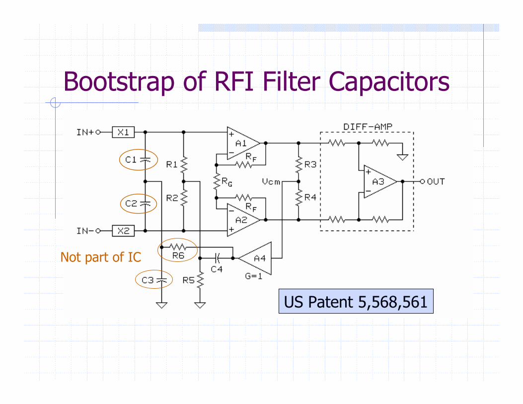
Bootstrap of RFI Filter Capacitors
US Patent 5,568,561
Not part of IC
InGenius® SummaryConventional active receivers are far cheaper, smaller, and lighter than a quality transformer, but …Transformers consistently outperform them for reasons that need to be widely understood and appreciatedThe main transformer advantage stems from its inherently very high common-mode impedancesThe InGenius® IC exhibits the very high CM impedances previously associated only with transformers
Excellent noise rejection even with UNBALANCED sources!Its bootstrap feature lends itself to novel and very effective RF interference suppressionIts high-quality internal op-amps give it GREAT SOUNDGREAT SOUND
Balanced Cable Issues
Capacitance imbalanceShielding for electric fields and RFImmunity to magnetic fieldsShield current induced noise (SCIN)
Shielding
Electric field couples to both signal conductors – coupling may be unequal
Twisting improves match by averaging physical distances to external field source
Grounded shield avoids problem by diverting field current to groundBraided shield of 85% to 95% coverage is usually adequate
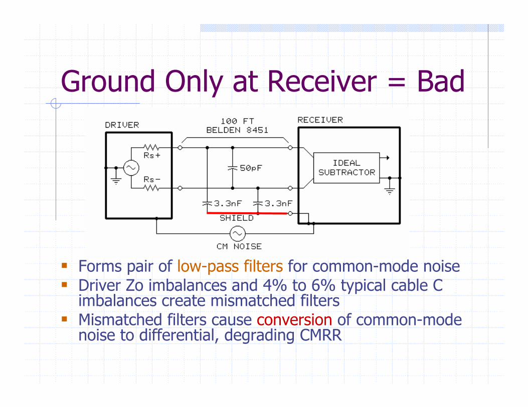
Ground Only at Receiver = Bad
Forms pair of low-pass filters for common-mode noise Driver Zo imbalances and 4% to 6% typical cable C imbalances create mismatched filtersMismatched filters cause conversion of common-mode noise to differential, degrading CMRR
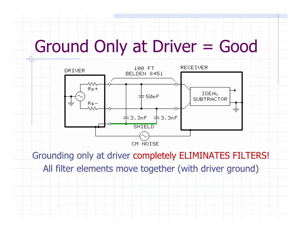
Ground Only at Driver = Good
Grounding only at driver completely ELIMINATES FILTERS!All filter elements move together (with driver ground)
Connections and CrosstalkSignal asymmetry and capacitance mismatch cause signal current flow in the shield
Grounding only at receiver forces current to return to the driver via an undefined path – can result in crosstalk, distortion, or oscillationGrounding only at driver allows current to return directly to the driver – NO PROBLEMS
The driver end of a balanced cable should always be grounded, whether or not the receiver end is grounded
Common-Mode Voltage Limits±10 volts (peak) for typical active circuits
Total loss of CMR if exceeded = very nasty distortion±250 volts for typical transformer
No audible effect if exceeded (only insulation failure) Voltage between driver & receiver ground
Less than few volts if both devices groundedCan approach 120 volts if either device ungroundedShield ground at both ends minimizesOther grounding required in some cases
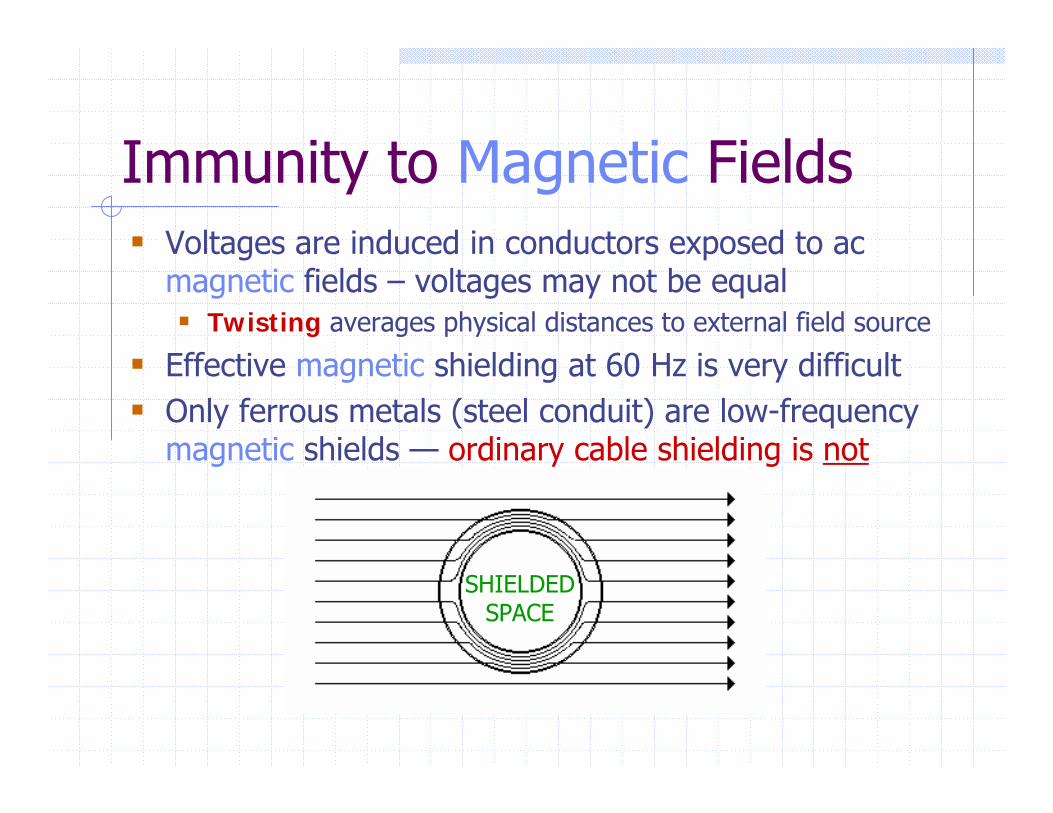
Immunity to Magnetic FieldsVoltages are induced in conductors exposed to ac magnetic fields – voltages may not be equal
Twisting averages physical distances to external field source
Effective magnetic shielding at 60 Hz is very difficultOnly ferrous metals (steel conduit) are low-frequency magnetic shields — ordinary cable shielding is not
SHIELDEDSPACE
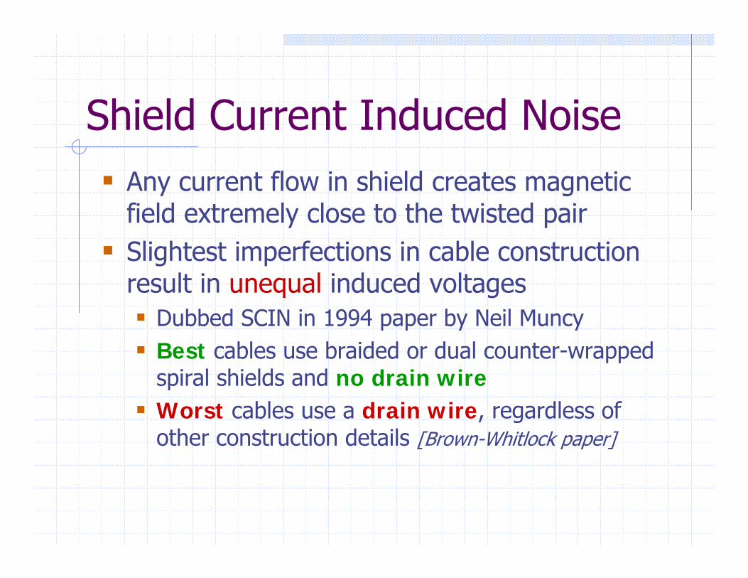
Shield Current Induced NoiseAny current flow in shield creates magnetic field extremely close to the twisted pairSlightest imperfections in cable construction result in unequal induced voltages
Dubbed SCIN in 1994 paper by Neil MuncyBest cables use braided or dual counter-wrapped spiral shields and no drain wireWorst cables use a drain wire, regardless of other construction details [Brown-Whitlock paper]
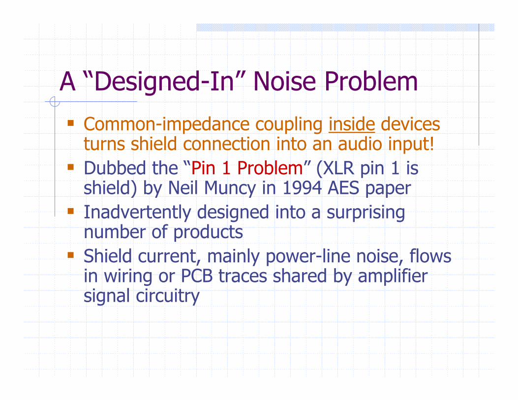
A “Designed-In” Noise Problem Common-impedance coupling inside devices turns shield connection into an audio input!Dubbed the “Pin 1 Problem” (XLR pin 1 is shield) by Neil Muncy in 1994 AES paperInadvertently designed into a surprising number of productsShield current, mainly power-line noise, flows in wiring or PCB traces shared by amplifier signal circuitry
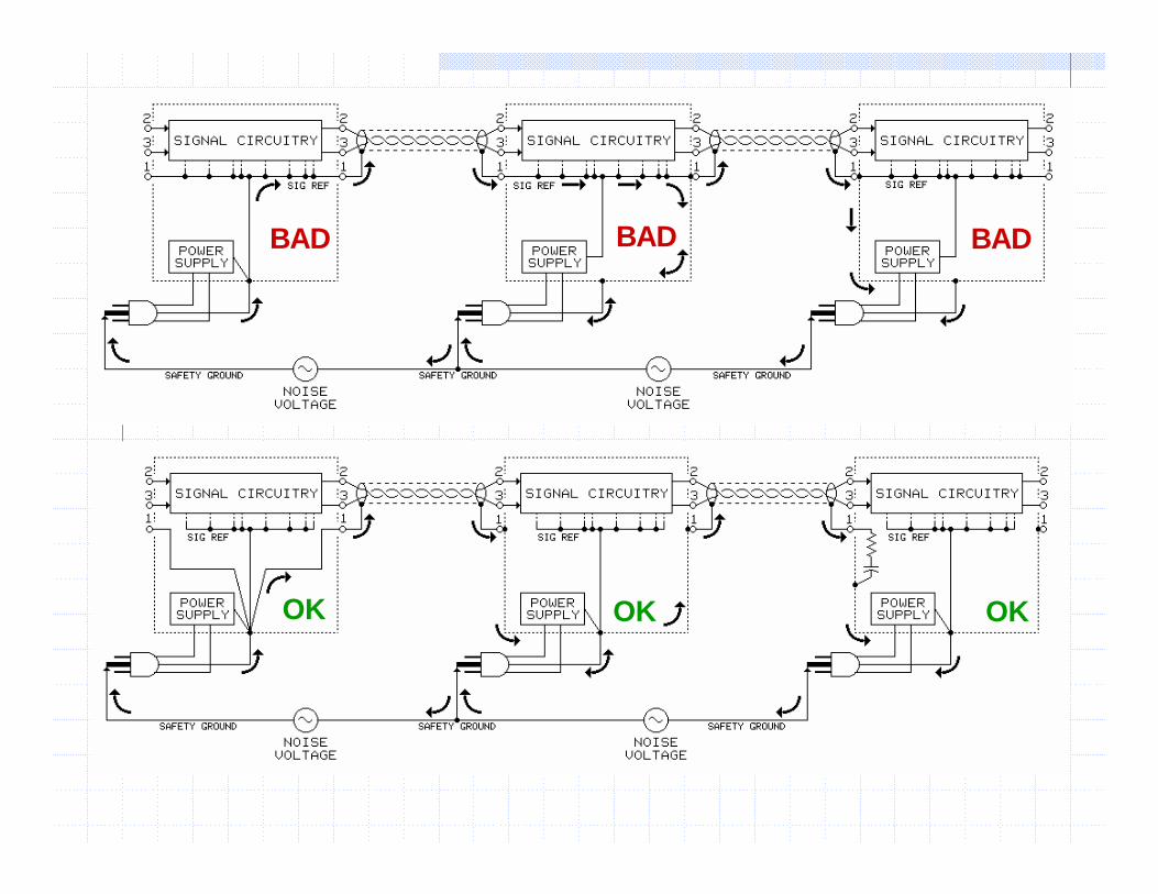
BAD BAD BAD
OK OK OK
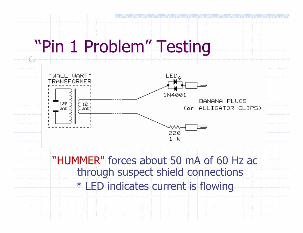
“Pin 1 Problem” Testing
“HUMMER" forces about 50 mA of 60 Hz ac through suspect shield connections* LED indicates current is flowing
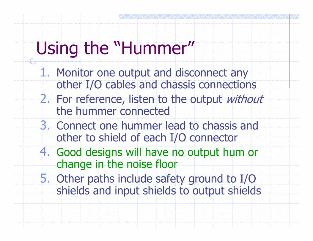
Using the “Hummer”1. Monitor one output and disconnect any
other I/O cables and chassis connections2. For reference, listen to the output without
the hummer connected3. Connect one hummer lead to chassis and
other to shield of each I/O connector4. Good designs will have no output hum or
change in the noise floor5. Other paths include safety ground to I/O
shields and input shields to output shields
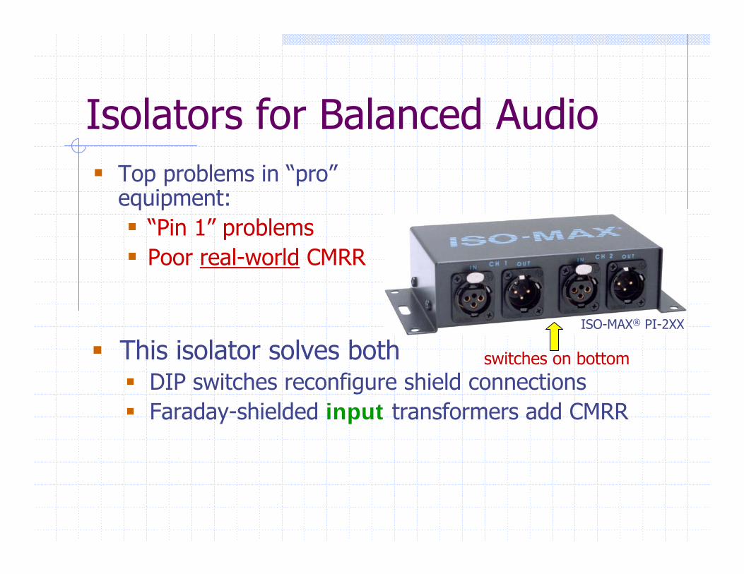
Isolators for Balanced AudioTop problems in “pro” equipment:
“Pin 1” problemsPoor real-world CMRR
This isolator solves bothDIP switches reconfigure shield connectionsFaraday-shielded input transformers add CMRR
switches on bottom
ISO-MAX® PI-2XX
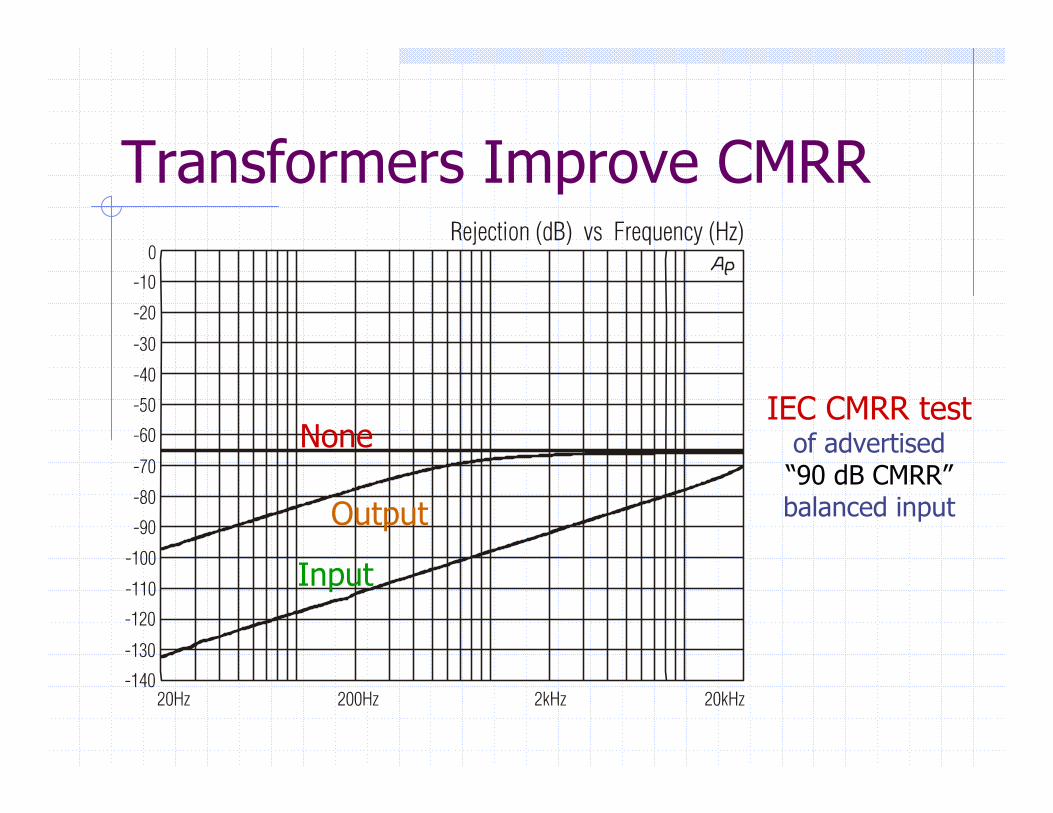
Transformers Improve CMRR
None
Output
Input
IEC CMRR testof advertised“90 dB CMRR”balanced input
Transformer PerformanceBeware “weasel-words” & “market-speak”
Missing specs or unspecified test conditionsLevel handling & distortion rated at 50 Hz
Jensen data complete and user-verifiableSonic transparency is the design goalLevel handling & distortion rated at 20 Hz
High level, low frequency distortion most tellingPhase distortion (deviation from linear phase) specified on every spec sheet
A Balanced ChecklistKeep balanced line pairs tightly twisted
Immunity to magnetic fieldsEspecially important in low-level mic circuits
Terminal blocks and XLRs vulnerable to magnetic fields“Star-Quad” mic cable reduces magnetic pickup 40 dB
Immunity to electric fields for unshielded pairsGrounding of cable shields is important
Always ground at the driverOK to ground at both endsNever ground only at the receiver
Unbalanced to Balanced AudioAKA “Consumer to Pro”Reference signal levels are different
Consumer ref = -10 dBV = 0.316 V rmsProfessional ref = +4 dBu = 1.228 V rmsRequires voltage gain of ~4x = 12 dB
Use a 1:4 step-up transformer?
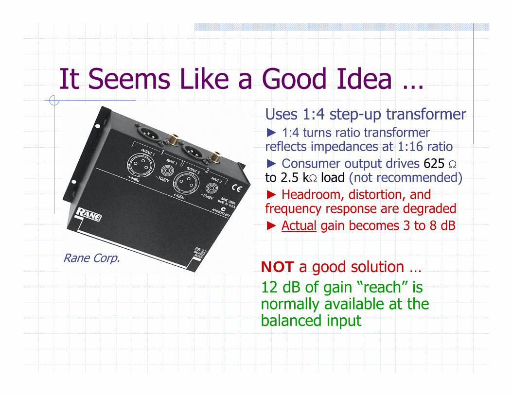
It Seems Like a Good Idea …Uses 1:4 step-up transformer 1:4 turns ratio transformer reflects impedances at 1:16 ratio Consumer output drives 625 Sto 2.5 kS load (not recommended) Headroom, distortion, and frequency response are degraded Actual gain becomes 3 to 8 dB
Rane Corp.NOT a good solution …12 dB of gain “reach” is normally available at the balanced input
Simple but SmartNoise rejection is usually issue, not gainUse of 2-conductor cable invites noise due to common-impedance couplingUse of 3-conductor cable stops ground noise current flow in signal conductors!
If input uses transformer or InGenius® IC, rejection can be up to 100 dB
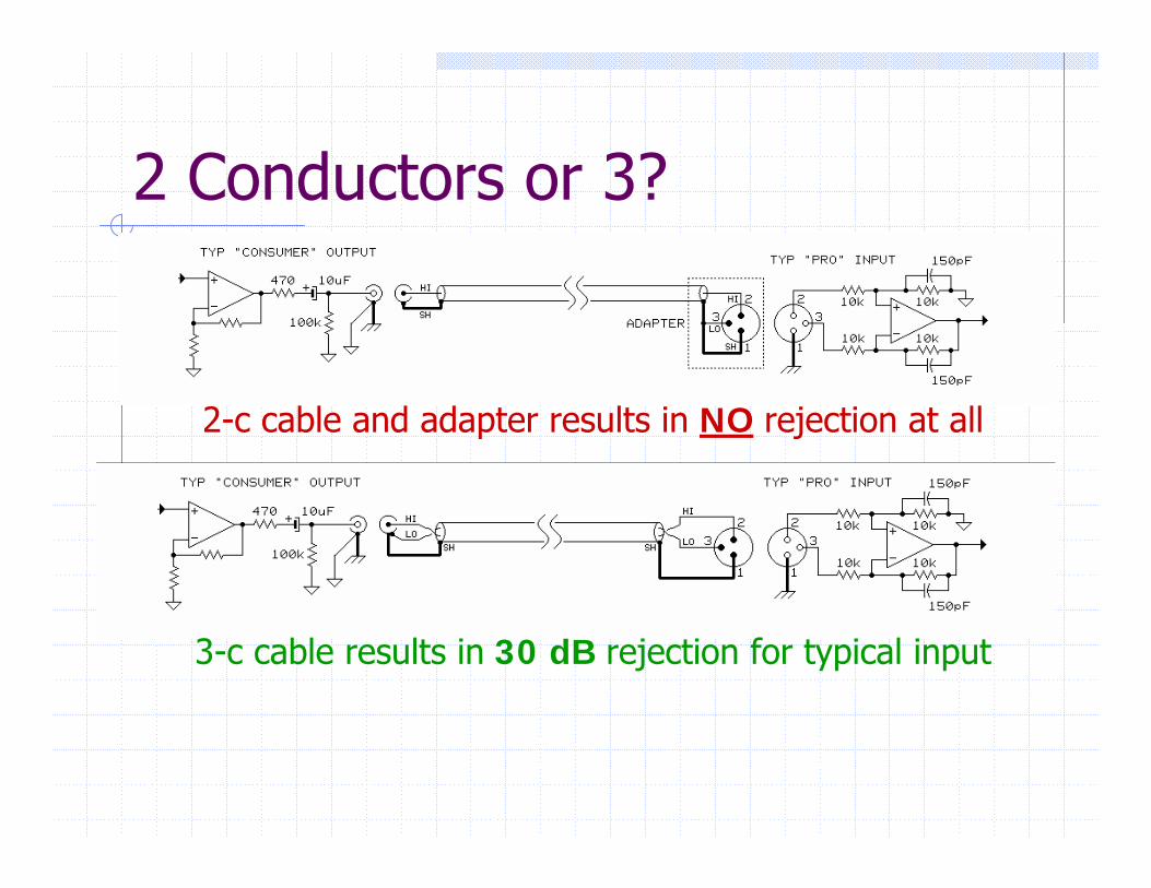
2 Conductors or 3?
2-c cable and adapter results in NO rejection at all
3-c cable results in 30 dB rejection for typical input
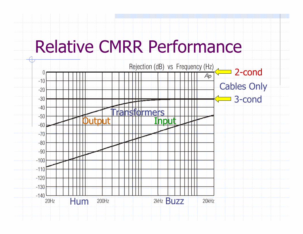
Relative CMRR Performance2-cond
3-cond
InputInputOutputOutput
Cables Only
Hum Buzz
TransformersTransformers
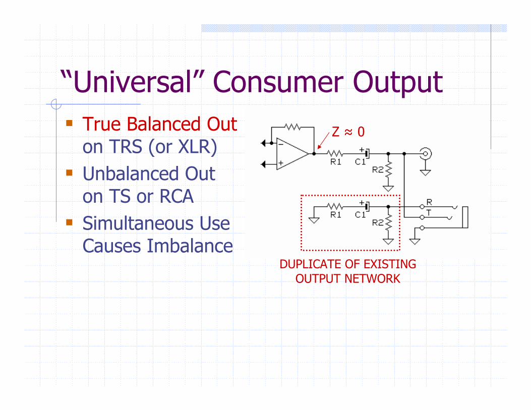
“Universal” Consumer OutputTrue Balanced Outon TRS (or XLR)Unbalanced Out on TS or RCASimultaneous Use Causes Imbalance
DUPLICATE OF EXISTING OUTPUT NETWORK
Z ≈ 0
Balanced to Unbalanced AudioAKA “Pro to Consumer”Signal level difference is legitimate concern
Consumer inputs easily over-driven by pro levelsRequires voltage loss of 12 dBLower pro output? – metering & noise degrade
One wiring method will NOT work for all kinds of line output circuits – it’s risky business!
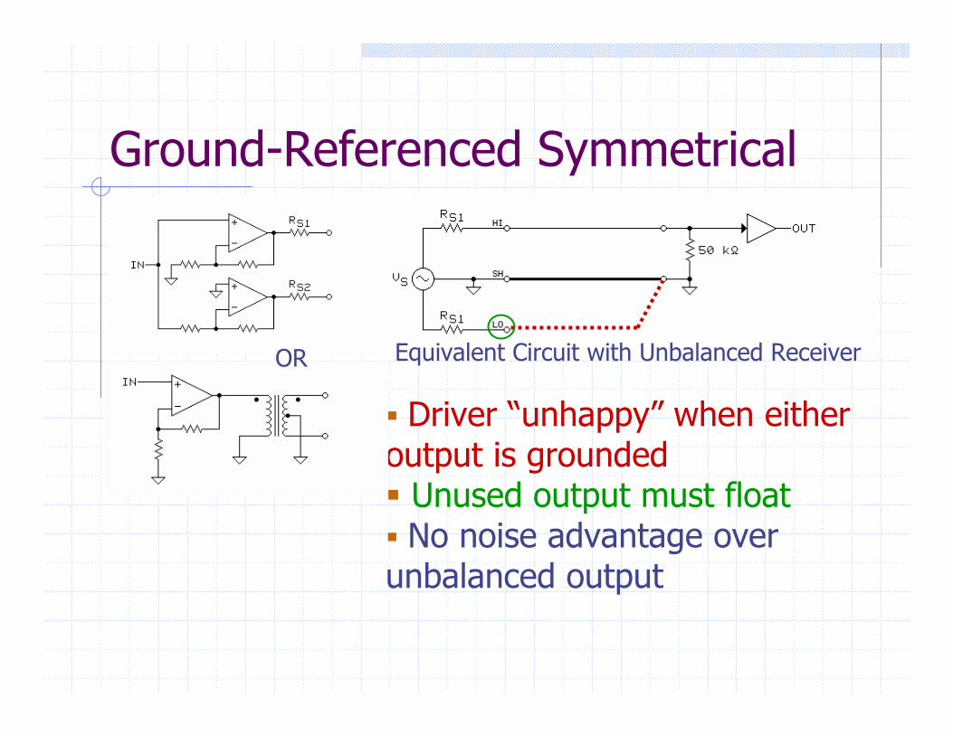
Ground-Referenced Symmetrical
Driver “unhappy” when either output is grounded
Unused output must floatNo noise advantage over
unbalanced output
Equivalent Circuit with Unbalanced ReceiverOR
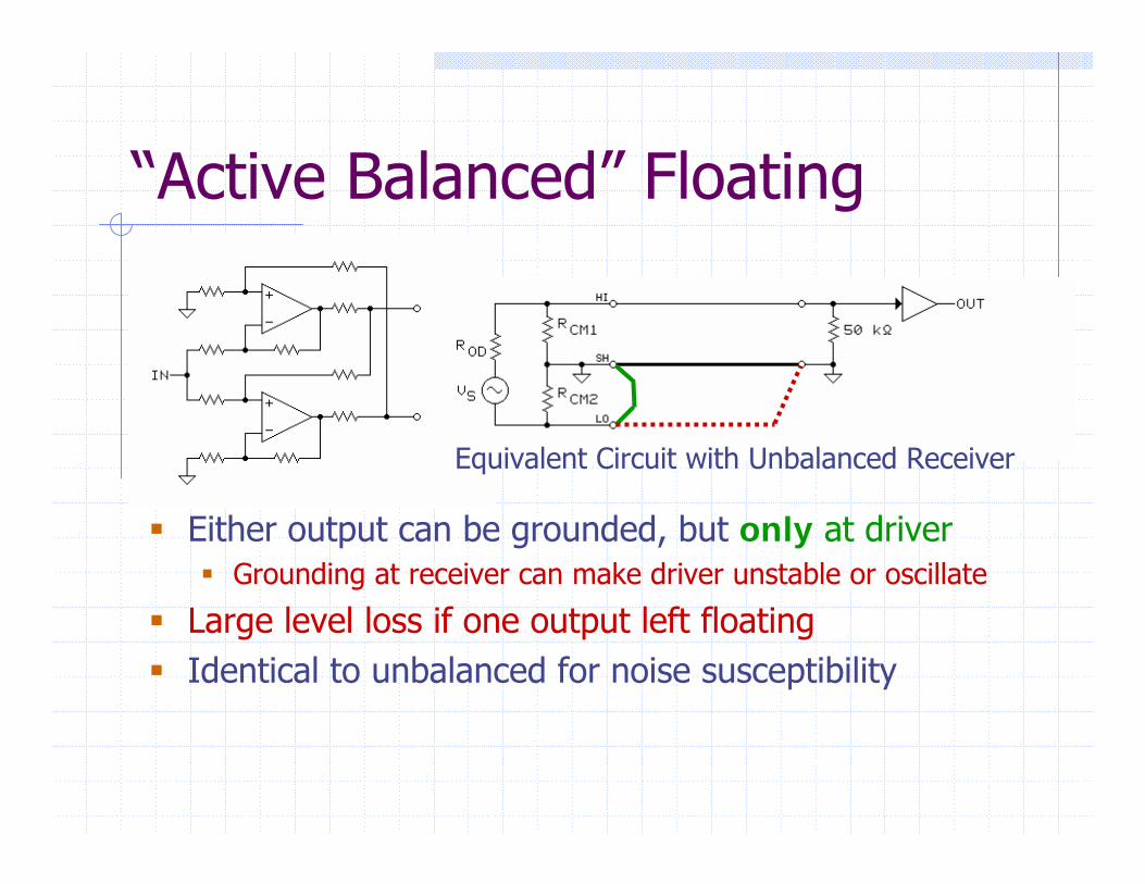
“Active Balanced” Floating
Either output can be grounded, but only at driverGrounding at receiver can make driver unstable or oscillate
Large level loss if one output left floatingIdentical to unbalanced for noise susceptibility
Equivalent Circuit with Unbalanced Receiver
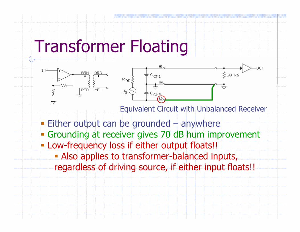
Transformer Floating
Either output can be grounded – anywhereGrounding at receiver gives 70 dB hum improvementLow-frequency loss if either output floats!!
Also applies to transformer-balanced inputs, regardless of driving source, if either input floats!!
Equivalent Circuit with Unbalanced Receiver
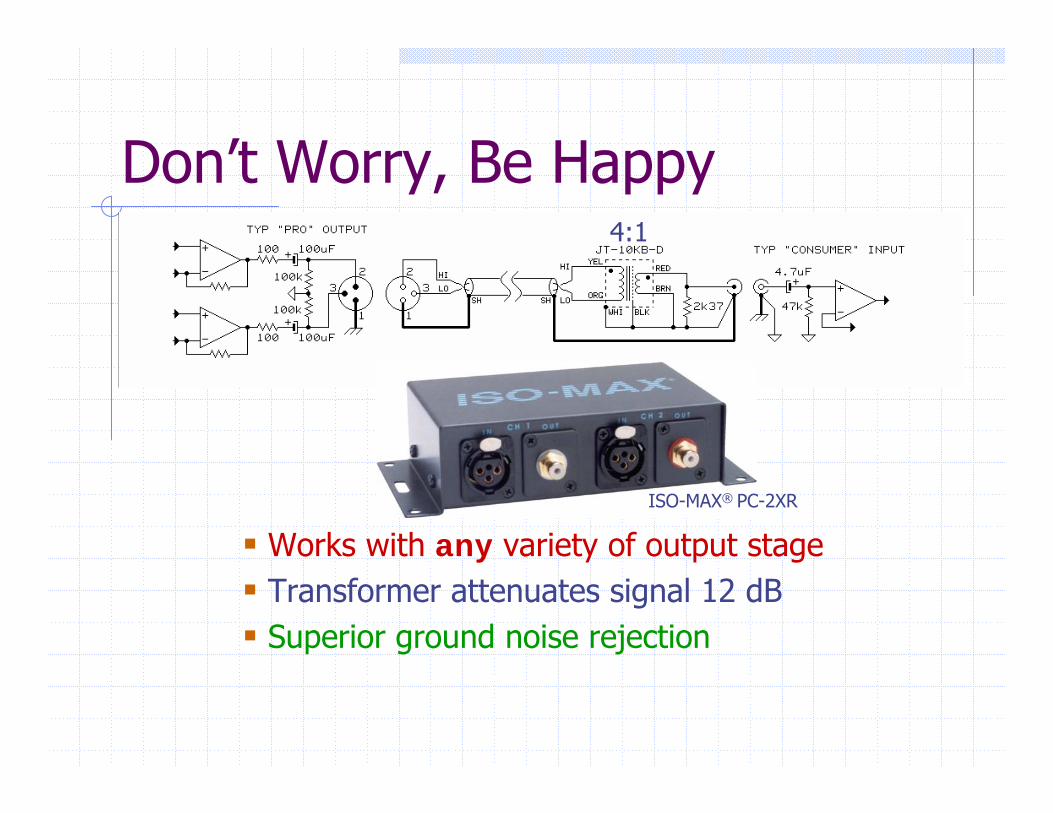
Don’t Worry, Be Happy
Works with any variety of output stageTransformer attenuates signal 12 dBSuperior ground noise rejection
ISO-MAX® PC-2XR
4:1
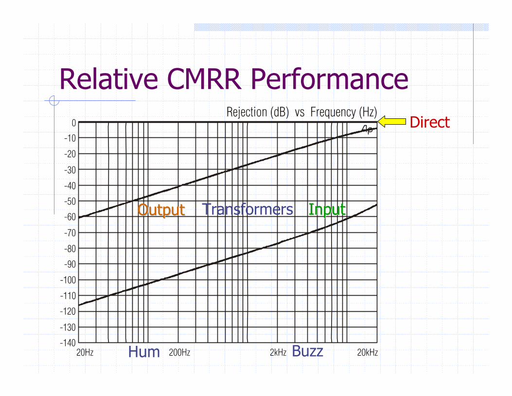
Relative CMRR PerformanceDirect
InputInputOutputOutput
Hum Buzz
Transformers
RF InterferenceElectromagnetic interference (EMI) difficult to avoid, especially in urban areas
RadiatedShort-wave, commercial, ham, and CB radioTV and FM broadcastRemote controls, wireless, and cell phonesRadar, medical, and industrial RF devices
Radiated and/or ConductedAM radioPower line arcing or corona dischargeMalfunctioning fluorescent or neon lightingElectric welders, brush motors, relays, and switches
Look AroundStrongest sources are often within building and conducted via power wiringMay share branch circuits with your systemSource may be part of your system!Light dimmers, fluorescent lights, CRT displays, and switch-mode power supplies are most common offenders

RF ImmunityGood equipment design requires itTesting now mandated in Europe, but CE mark is no guaranteeMost equipment today has poor immunitySymptoms
Background voices, music, tones, clicks, etc.TV signal causes buzz almost identical to 60 Hz“Veiled" or "grainy" quality in audio“Herringbone” patterns in videoOtherwise unexplained behavior in digital systems
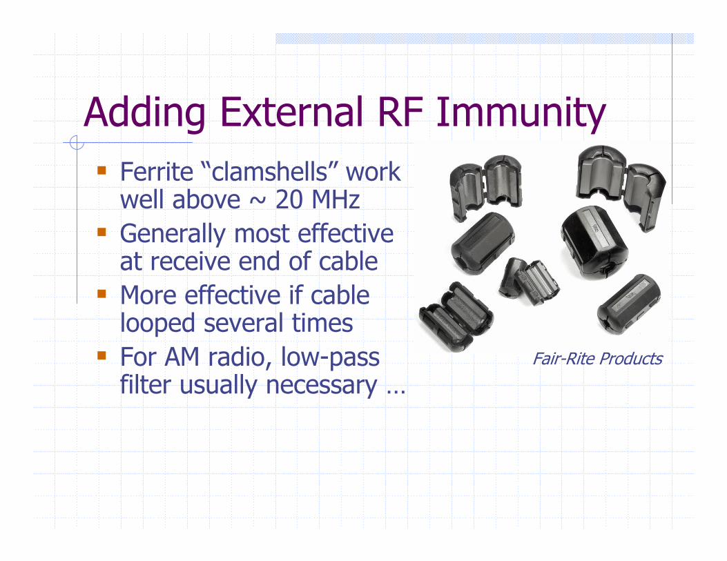
Adding External RF ImmunityFerrite “clamshells” work well above ~ 20 MHzGenerally most effective at receive end of cableMore effective if cable looped several timesFor AM radio, low-pass filter usually necessary …
Fair-Rite Products
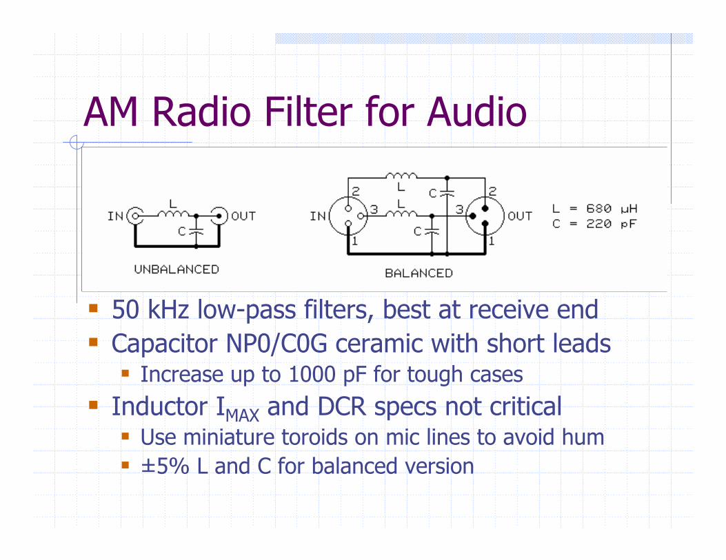
AM Radio Filter for Audio
50 kHz low-pass filters, best at receive endCapacitor NP0/C0G ceramic with short leads
Increase up to 1000 pF for tough casesInductor IMAX and DCR specs not critical
Use miniature toroids on mic lines to avoid hum±5% L and C for balanced version
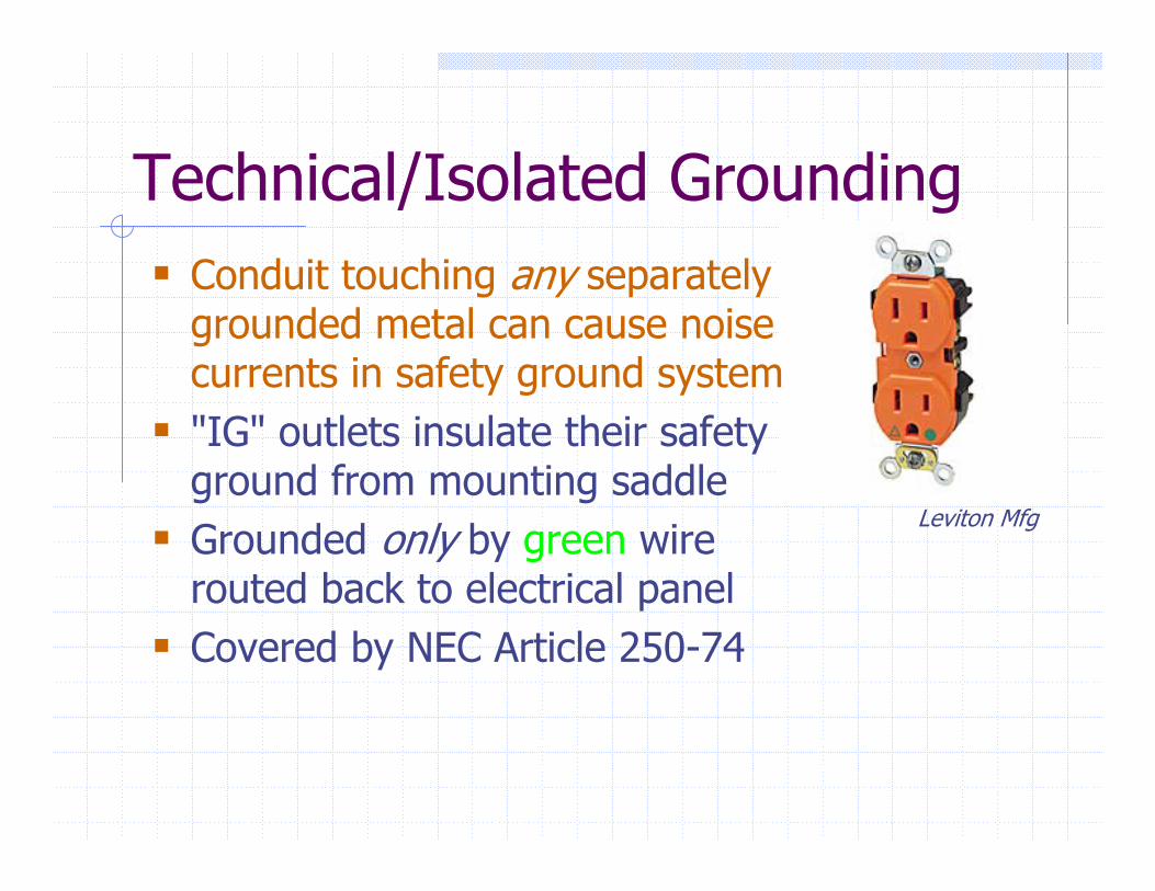
Technical/Isolated GroundingConduit touching any separately grounded metal can cause noise currents in safety ground system"IG" outlets insulate their safety ground from mounting saddleGrounded only by green wire routed back to electrical panelCovered by NEC Article 250-74
Leviton Mfg
Blame the Power Line?"Today’s residential systems contractors face
unprecedented challenges where high resolution, trouble-free operation is required. From inducing AC ground loops, video hum bars, static bursts, damage from AC line surges and variable audio and video performance, comprehensive control and conditioning of AC power is no longer an option.“
… product training descriptionby well-known manufacturer
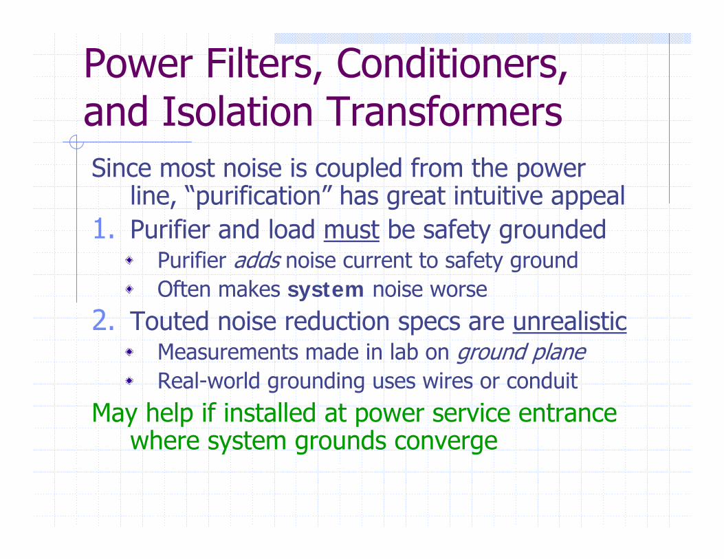
Power Filters, Conditioners, and Isolation TransformersSince most noise is coupled from the power
line, “purification” has great intuitive appeal1. Purifier and load must be safety grounded
Purifier adds noise current to safety groundOften makes system noise worse
2. Touted noise reduction specs are unrealisticMeasurements made in lab on ground planeReal-world grounding uses wires or conduit
May help if installed at power service entrance where system grounds converge
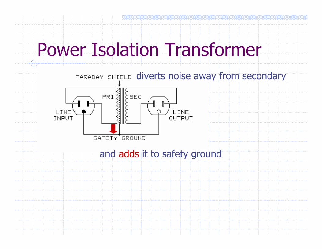
Power Isolation Transformer
and adds it to safety ground
diverts noise away from secondary
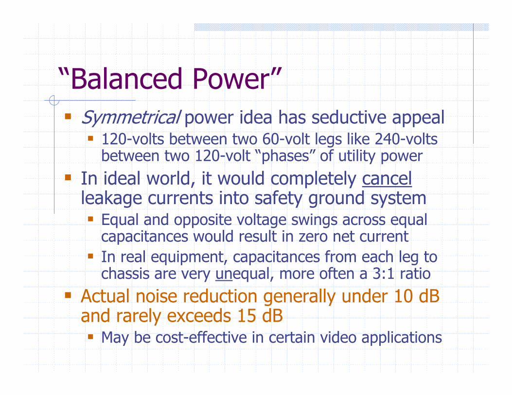
“Balanced Power”Symmetrical power idea has seductive appeal
120-volts between two 60-volt legs like 240-volts between two 120-volt “phases” of utility power
In ideal world, it would completely cancelleakage currents into safety ground system
Equal and opposite voltage swings across equal capacitances would result in zero net currentIn real equipment, capacitances from each leg to chassis are very unequal, more often a 3:1 ratio
Actual noise reduction generally under 10 dB and rarely exceeds 15 dB
May be cost-effective in certain video applications
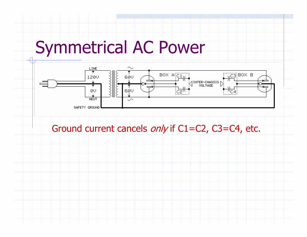
Symmetrical AC Power
Ground current cancels only if C1=C2, C3=C4, etc.
Do They Work?
Improvements, if any, are generally marginalMore cost-effective to identify and treat point(s) where power line couples to signalMany benefits ascribed to “power treatment” schemes are actually due to plugging all system equipment into the same outlet strip or branch circuit – always a good idea!
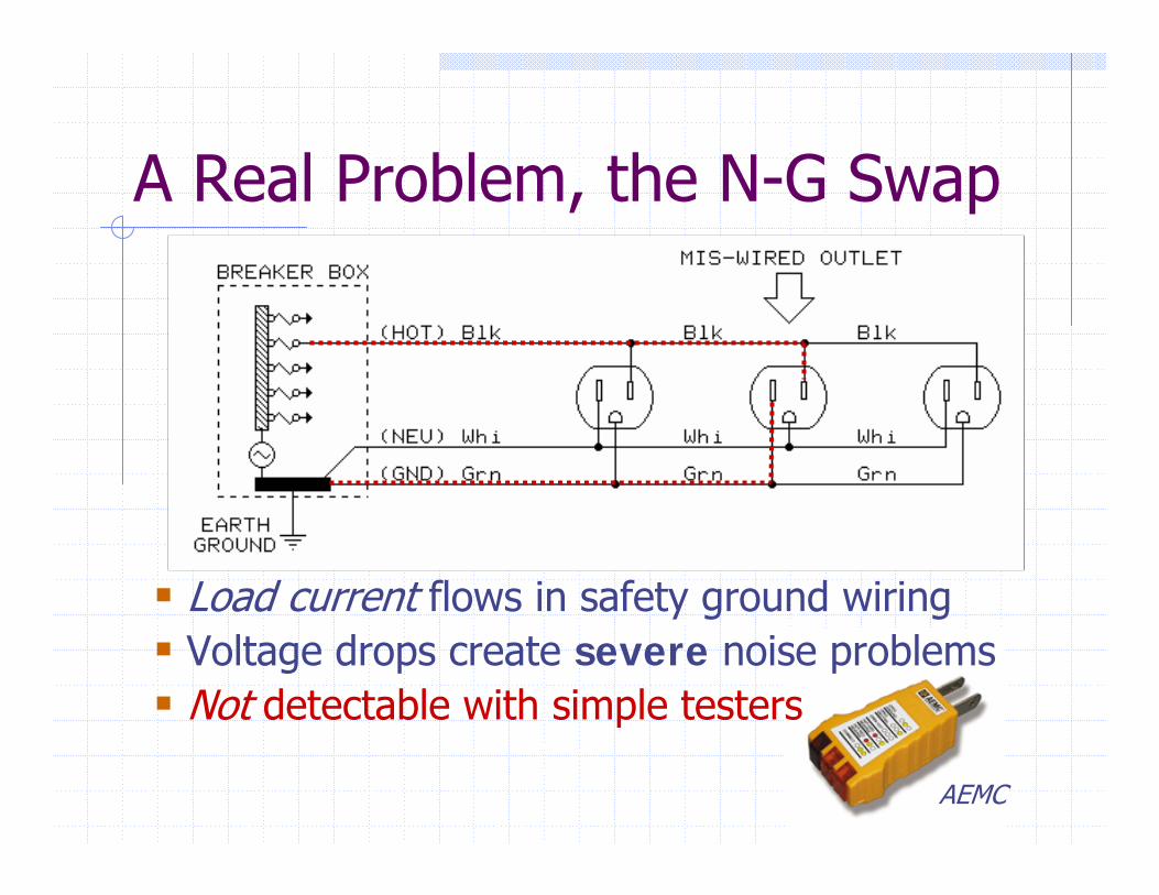
A Real Problem, the N-G Swap
Load current flows in safety ground wiringVoltage drops create severe noise problemsNot detectable with simple testers
AEMC
About Surge SuppressionFear and pseudo-science are often used to sell surge protection devicesMindless use of conventional suppressors can actually increase equipment damage risk!The most widely-used suppressors employ three MOV (metal-oxide varistor) devices that divert surges into the safety ground systemSurges generate brief but extremeextreme voltage differences in the safety ground systemEquipment interfaces are often damaged …
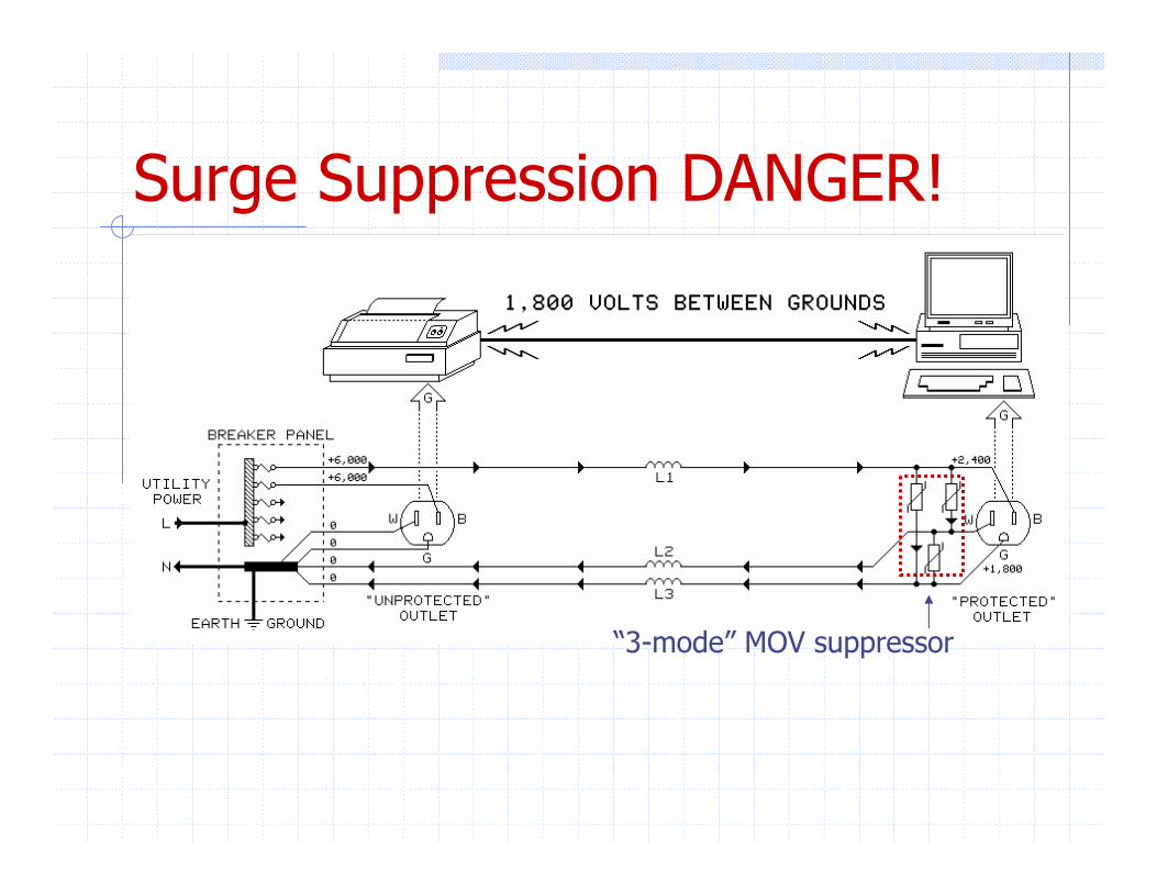
Surge Suppression DANGER!
“3-mode” MOV suppressor
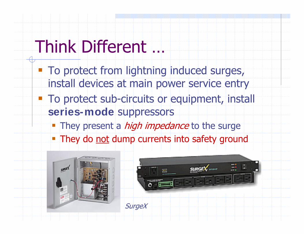
Think Different …To protect from lightning induced surges, install devices at main power service entryTo protect sub-circuits or equipment, install series-mode suppressors
They present a high impedance to the surgeThey do not dump currents into safety ground
SurgeX
Thanks for Your Attention!“Handbook for Sound Engineers”includes Whitlock chapters on: Audio Transformers Microphone Preamplifiers Grounding and Interfacing
Think of a question [email protected]