an optimum design for 3-d fixture synthesis in a point set domain
TRANSCRIPT

IEEE TRANSACTIONS ON ROBOTICS AND AUTOMATION, VOL. 16, NO. 6, DECEMBER 2000 839
[3] L. Ferriere and B. Raucent, “RollMOBS, a new universal wheel con-cept,” in Proc. 1998 IEEE Int. Conf. Robotics and Automation, vol. 3,1998, pp. 1877–1882.
[4] S. Halme, T. Schonberg, and Y. Wang, “Motion control of a sphericalmobile robot,” inProc. AMC’96, 1996.
[5] V. Jurdjevic, “The geometry of the plate-ball problem,”Arch. Ration.Mech. Anal., vol. 124, pp. 305–328, 1993.
[6] G. Lafferriere and H. Sussmann, “A differential geometric approach tomotion planning,” inNonholonomic Motion Planning, Z. Li and J. F.Canny, Eds. Norwell, MA: Kluwer, 1993, pp. 235–270.
[7] J. P. Laumond, “Nonholonomic motion planning for robots,” presentedat the IEEE International Conference on Robotics and Automation,1998. Tutorial Notes.
[8] R. Mukherjee, B. Emond, and J. L. Junkins, “Optimal trajectory plan-ning for mobile robots using Jacobian elliptic functions,”Int. J. Robot.Res., vol. 16, no. 6, pp. 826–839, 1997.
[9] R. R. Murray, Z. Li, and S. S. Sastry,A Mathematical Introduction toRobotic Manipulation. Boca Raton, FL: CRC Press, 1993.
[10] R. Roberson and R. Schwertassek,Dynamics of Multibody Sys-tems. New York: Springer-Verlag, 1988.
[11] M. Schlemmer and S. K. Agrawal, “Globally feedback linearizable time-invariant systems: Optimal solution for Mayer’s cost,”ASME J. Dyn.Syst. Measure. Contr., vol. 120, no. 2, pp. 343–347, 2000.
[12] X. Xu and S. K. Agrawal, “Finite-time optimal control of polynomialsystems using successive approximation,”J. Optim. Theory Applicat.,vol. 105, no. 2, pp. 477–489, May 2000.
An Optimum Design for 3-D Fixture Synthesis in a PointSet Domain
Michael Yu Wang, Member, IEEE
Abstract—This article addresses the problem of fixture synthesis for 3-Dworkpieces with a set of discrete locations on the workpiece surface as apoint set of candidates for locator and clamp placement. A sequential opti-mization approach is presented in order to reduce the complexity associatedwith an exhaustive search. The approach is based on a concept of optimumexperimental design, while the optimization focuses on the fixture perfor-mance of workpiece localization accuracy. In using the D-optimality crite-rion to minimize the workpiece positioning errors, two different greedy al-gorithms are developed for force-closure fixturing in the point set domain.Both 2-D and 3-D examples are presented to illustrate the effectiveness ofthe synthesis approach.
Index Terms—Fixture synthesis, form-closure, greedy algorithms,workholding.
I. INTRODUCTION
This article describes a research approach to automatic synthesis ofa class of fixtures for three-dimensional (3-D) workpieces. A fixtureis represented as a collection of fixels, i.e., a set of point locators andclamping elements. For the class of fixtures considered, the fixels mustbe applied to the workpiece at the locations from a collection of spec-ified locations on the workpiece surfaces. In general, the set of fix-ture locations available is assumed to be potentially large; for example,the locations might be generated by discretizing the exterior surfaces
Manuscript received March 8, 2000; revised September 29, 2000. This paperwas recommended for publication by Associate Editor J. Ponce and Editor A. DeLuca upon evluation of the reviewers’ comments.
The author is with the Department of Mechanical Engineering, University ofMaryland, College Park, MD 20742 USA.
Publisher Item Identifier S 1042-296X(00)11576-9.
of the workpiece. The goal of fixture synthesis is to determine an op-timal or suboptimal fixture that satisfies fixturing functional require-ments, usually among a vast set of feasible configurations. The fix-turing requirements include essentially kinematic localization and totalfixturing (i.e., form-closure). The optimization objective is to mini-mize the workpiece positional errors due to workpiece surface and fixelset-up errors.
Thus, the task of fixture synthesis in the point set domain becomesan optimal selection of six locators and one or more clamps among thegivenN candidate locations. A direct method is the exhaustive search,but it would become impractical for a large number of candidates. Theproblem is combinatorial in its complexity, and one needs to use anefficient method for a practical solution.
In the approach presented in the paper, the fixture synthesis problemis described as a “design of experiments” in the framework of statisticalanalysis. The objective of minimizing the workpiece positioning errorsis defined as the so-calledD-optimality. This leads to the applicationof an efficient method ofgreedyalgorithms widely used in optimumexperimental design. The “greedy” method allows us to find a satisfac-tory fixture, often suboptimal, without resorting to a complete searchof exhaustive type.
II. RELATED WORK
In general, a study of workpiece fixturing suggests one of two kindsof problems: 1) fixture analysis and 2) fixture synthesis. The problemof fixture analysis is to determine the performance of a given fixturingscheme under a set of fixturing requirements such as force closure.Many efficient solution techniques for this problem are reported in theliterature. On the other hand, fixture synthesis requires determining afixturing layout to meet a given set of performance requirements. Theanalysis problem seems to have received far more attention than thesynthesis problem in the literature [1].
The essential requirement of fixturing is the century-old conceptof force closure[2], which has been extensively studied in recentyears [3]–[5]. There are several formal methods for fixture analysisbased on the classical screw theory [6], [7] or geometric perturbationtechniques [8], [9]. Conventional fixture synthesis procedures suchas “3-2-1” rules have been described in traditional design manuals[10]. There has been some progress in automatic fixture design withfeature-based, geometric-reasoning, or heuristic approaches [11]–[13].However, the success of these approaches has been limited to partswith prismatic or other simple features. Fixture synthesis tools areyet to emerge for general 3-D workpieces such as turbine airfoils.Recently, the problem of designing modular fixtures has gained muchattention [9], [14], [15], but the new algorithms developed thus far areonly for two-dimensional (2-D) or 2 1/2–D polygonal or polyhedralparts. Modular fixtures are difficult to implement for complex shaped3-D parts, and this fact is evident in industrial production of turbineairfoils.
Extensive research on machining fixture designs is reported recently[16], [17]. A nonlinear programming method is used in [16], similarto an approach to robotic grasping [5]. The method cannot deal withproblems of combinatorial nature and is computationally inefficient. Amixed integer programming method with a finite element workpiecemodel is proposed in [17]. Unfortunately, the method is demonstratedto be effective only for a small scale design, such as additional supportconsiderations. There have also been extensive research activities in theareas of tool accessibility and path clearance, and process planning.Additional results in fixture analysis and design are reviewed in [12]and [9].
1042–296X/00$10.00 © 2000 IEEE

840 IEEE TRANSACTIONS ON ROBOTICS AND AUTOMATION, VOL. 16, NO. 6, DECEMBER 2000
III. POINT SET FIXTURE SYNTHESIS PROBLEM
In a typical fixture synthesis problem, a large portion of continuoussurfaces of the workpiece are often assumed to be available for fixelplacement. However, a different situation may arise that the fixture ele-ments are allowed to contact with the workpiece only at a set of discretepoint locations instead. In general, the set of fixel locations availablecould be potentially large. Thispoint-setconstraint might be imposedby practical conditions related to the functional and/or manufacturingrequirements of the part. A good example is a turbine airfoil, whosegeometric shape is primarily defined by its aerodynamics. The geo-metric shape, however, is usually approximated by parametric surfacessuch as B-splines in its geometric representation of a CAD system.Only a dense set of points of the surfaces are defined exactly as cal-culated in the aerodynamic analysis. In order to minimize the effectsof the geometric approximation, the airfoil is required to be fixtured atsome of these precise surface locations in its manufacture and inspec-tion processes. Another example is to discretize all exterior surfaces ofthe workpiece to create a set of candidate fixture locations for the fix-ture design. This has been a topic of interest in multiple body fixturing[18], [19].
In the point set domain, a fixture is described as follows. Let usdenote theN permissible surface locationsrrrk = fx; y; zgTk (k =1; . . . ; N ) on the workpiece by�, which are assumed to be practi-cally feasible for fixturing. A fixture is represented as a collection oftwo distinct sets
fL; Cg
and
L = frrrig; i = 1; . . . ; n; n = 6
C = frrrjg; j = 1; . . . ; c; c � 1
all rrri; j 2 �
wherefLg is a locator set andfCg a clamp set. Locators are essen-tial for providinguniqueandaccuratelocation (both position and rota-tion) of the workpiece with respect to a fixture reference frame. Theyalso provide support forforce-closureafter clamping. The part-locatingfunction is calledlocalization, and for unique localization exact 6 loca-tors must be used in 3-D (or three locators in 2-D). It should be notedthat locators are passive elements. A clamp is represented as a forceapplied on the workpiece to provide a complete restraint of the work-piece against any external forces on the workpiece. At least one clampis needed.
One obvious problem in dealing with the large numberN of candi-date locations is the complexity in selecting an appropriate set of fixels.For example, to select seven points from 100 locations, one has to eval-uate more than 16 billion combinations. For an airplane turbine blade,the candidate locations are typically in thousands. Clearly, exhaustivesearches are not practical and an efficient technique is required for op-timal or suboptimal fixture synthesis.
IV. OPTIMAL WORKPIECELOCALIZATION
The functional requirements of a fixture are defined by the kinematicconstraints imposed on the workpiece being held by the fixture. Thesekinematic conditions are well understood [8], [4], [6]. In the point setdomain, while there may exist a vast number of feasible solutions that intheory satisfy the fixturing requirements, performance characteristicsof these solutions may vary drastically. For a specific application, it isimportant to find the most suitable fixturing scheme.
A fundamental aspect of fixture performance is the positioning ac-curacy of workpiece localization. The positioning accuracy is subjectto positional variability of the locators and geometric variability of theworkpiece. In general, the locator positional variability depends on thedimensioning and tolerancing scheme assigned to the fixture assemblyand its components. A complete model of the variability is usually notavailable at the early stage of fixture design. However, the impact of alocating scheme can be predicted based on a statistical characterizationof the positional variability. With this basis, an optimal locating schemewould minimize workpiece positional variations due to the locator po-sitioning errors. When also satisfying the clamping and force-closureconditions, such a fixture is referred to as anoptimal fixture. This is thefocus of the synthesis approach proposed in this article.
A. Fixture Model
In order to facilitate deriving the optimal synthesis method, we needan appropriate fixture model. This has been well studied in the literature[8], [6], [16]. We adapt the geometric model of but with an algebraicinterpretation. For clarity, we describe the model for fixtures of pointcontacts without friction and for rigid workpiece. At each contact, asurface normal is assumed to be well defined. At the end of the paper,extensions to include finite contact regions, friction, and contact com-pliance are discussed.
Following the geometric perturbation analysis presented in [8],workpiece geometric boundary is represented by a piecewise dif-ferentiable functiong in terms of body-embedded coordinatesrrr asg(rrr) = 0. Suppose that theith locator is in contact with the workpiece,then it would satisfy the workpiece surface functiong(rrri) = 0.
Let’s introduce a small perturbation in the location of the workpiece�qqqT = f�bbbT ����T g, including both the orientation and the position.This perturbation results in a perturbation in the function valueg(rrri)
�gi = �g(rrri) = �[rgTi (rrri �rgi)T ] �qqq (1)
wherergi = rg(rrri) = @g=@rrri is the gradient vector of functiong(rrr). Here,�gi is known as thealgebraic distanceof a point separatedfrom a geometric surface [20]. For a piecewise differentiable workpiecesurface, the algebraic distance can be normalized with respect to thenormkrgik of the gradient vector to yield the following perturbationequation:
�gi=krgik = �[nnnTi (rrri � nnni)
T ] �qqq (2)
wherennni = rgi=krgik, defining the unit normal at theith contactpoint on the surface. We rewrite the equation as
�yi = hhhTi �qqq where hhhT
i = �fnnnTi (rrri � nnni)
T g (3)
with the normalized algebraic distance�yi = �gi=krgik. It is alsoeasy to show that
�yi = nnnTi �rrri (4)
where�rrri is the resulting perturbation of the locator position vectorrrri with respect to the workpiece. Thus,�yi represents the projection ofthe locator positional error along the normal direction of the workpiecesurface.
For a fixture ofn locators, a collection of their individual perturba-tion equations is defined by
�yyy = GGGT �qqq (5)

IEEE TRANSACTIONS ON ROBOTICS AND AUTOMATION, VOL. 16, NO. 6, DECEMBER 2000 841
where�yyy = f�y1 �y2 � � � �yngT andGGG = [hhh1 hhh2 � � � hhhn]. Here, ma-
trix GGG is called thelocator matrixand it is defined entirely by the lo-cator locations specified on the workpiece surface.
B. Optimal Localization
From (5), we have
k�yyyk = �yyyT �yyy = �qqqT (GGGGGGT ) �qqq (6)
which shows that the fixture localization errors�qqq are on the same oderof magnitude as the locator positioning errors�yyy and, clearly, they de-pend on locations of the locators as defined by the locator matrixGGG.The primary objective of our optimal fixture synthesis is to minimizethe localization errors�qqq.
In general, the locator positioning errors�yyy depend on the dimen-sioning and tolerancing scheme assigned to the fixture assembly andits components. In the early stage of fixture design, only variations ortolerances of the error sources may be known. Therefore, the locator er-rors may be considered as statistical variables. If it is assumed that thelocator errors follow independent normal distributionN(0; �2), thenvariances of the localization error�qqq are given as
var (�qqq) = �2(GGGGGGT )�1: (7)
Here, from a statistical viewpoint matrixGGGGGGT completely character-izes the total variance in the workpiece position and orientation. Weshall denote thatMMM = GGGGGGT and shall refer it to ascontact informa-tion matrix(also known as Fisher information matrix in statistics).
C. D-Optimality
The task now is to choose a suitable design criterion to achieve thedesign objective of high localization accuracy such that the other fixturerequirements are satisfied. The optimal criterion chosen is the determi-nant of the locator information matrixMMM = GGGGGGT . This is known asD-Optimality [21], and the D-optimal synthesis using this criterion isdefined as
maxdet(MMM) where MMM = GGGGGGT : (8)
The D-optimality criterion has three important and suitable features.First, the D-optimal design minimizes the variance of the workpiecepositional parameters�qqq, and thus reduces the overall effect of the lo-cator positional errors on the localization accuracy. Second, the D-op-timal design reduces the interactions between locators, so the six de-grees of rigid-body freedom of the workpiece are best separated amongthe given locators [22, p. 124]. From a geometric point of view, the de-terminant criterion implies that the columns of locator matrixGGG aremade to be as orthogonal as possible. This makes particular locatorsmore sensitive to particular workpiece positional parameters. Third, aD-optimal synthesis can be constructed efficiently with greedy algo-rithms to be discussed next.
V. SEQUENTIAL OPTIMIZATION FOR FIXTURE SYNTHESIS
As we mentioned in Section III, the major difficulty of fixture syn-thesis in the point set domain is the combinatorial complexity in a com-plete search for theglobal optimal fixture. For practical purpose, wemay have to resort to a more efficient method with a tradeoff to obtaina suboptimalsolution. In our case of optimal localization, if the local-ization errors are reduced within a specified range, the resulting fixturedesign would be considered acceptable.
For the D-optimal synthesis, an efficient technique is made possibleby exploiting an incremental change of the locator information matrixwith respect to a sequential deletion of locators from the candidate set.Consider the effect of deleting one location fromN candidateshhhi (i =1; 2; . . . ; N). The locator information matrixMMM before any deletioncan be written as
MMM = GGGGGGT =
n
i=1
hhhihhhTi : (9)
Now suppose thejth location is to be deleted and letGGG(j) andMMM (j)
denote the respective locator matrixGGG and the information matrixMMMwith thejth location deleted. Clearly, we have
MMM (j) = GGGGGGT � hhhjhhhTj : (10)
With some straightforward linear algebra manipulations [21], the de-terminant of matrixMMM (j) is found to be
detMMM (j) =(1� pjj)(detMMM) (11)
pjj =hhhTj MMM�1hhhj : (12)
Further, the inverse of matrixMMM (j) can be updated as
MMM�1(j) =MMM�1 + (MMM�1hhhj)(MMM
�1hhhj)T =(1� pjj): (13)
In fact,pjj is a diagonal element of the so-calledprediction matrixGGGT (GGGGGGT )�1GGG, and it is easy to show that0 � pjj � 1. Clearly,the determinant is nonincreasing with respect to any deletion. Equa-tion (12) indicates the influence of thejth location ondet(MMM), aspjjrepresents the exact fractional change in the determinant if thejth lo-cation is to be deleted. Hence, the deletion of the location associatedwith the smallestpjj value in the current location set would result inthe smallest possible reduction ofdet(MMM), which in turn leads to thesmallest impact on the positioning error of the workpiece being local-ized.
This observation naturally leads to a numerical procedure for op-timal locator synthesis. Starting from allN initial candidate locations,an iterative process is involved to sequentially delete one candidate lo-cation at a time, leading to a final set of six locators. At each iteration,the location of deletion is chosen such that
min(pjj = hhhTj MMM�1hhhj): (14)
For this reason, the technique is calledsequential optimal localization.This technique essentially reduces the search for a D-optimal
synthesis to a sequence of efficient algebraic evaluations. Equations(10)–(13) define the recursive formula for updatingMMM (j), MMM
�1(j) , and
detMMM (j). Particularly, the inverse needs to be calculated only oncefor the initial MMM . The technique is rooted to the concept of optimaldesign of experiments [21] and has been employed for parameteridentification problems of similar nature [23], [24].
It should be noted that the sequential optimization is a greedymethod for a discrete optimization problem. It does not guaranteethat the global optimum will be reached. However, by deleting onlythe location of the least impact, the loss of localization accuracy isalways kept to be minimum at each deletion iteration. If more thanone location is deleted in each iteration, the number of cases to beconsidered at a time will be combinatorially exploded [21]. Further,more rapid reduction ofdetMMM tends to result in a lesser optimalsolution.

842 IEEE TRANSACTIONS ON ROBOTICS AND AUTOMATION, VOL. 16, NO. 6, DECEMBER 2000
At this juncture, we describe the condition of form-closure for com-plete fixture solutions with a consideration of clamp selection. Theform-closure condition is well understood [8], [4], [6], and it is suffi-cient to describe it for the case of a single clamp. The clamp is in pointcontact at locationrrrc perpendicular to the workpiece surface. For fric-tionless contact, the clamping force exerted on the workpiece is givenas
FFF c = �fnnnT
c (rrrc � nnnc)T gT�c = hhhc�c (15)
where�c denotes the clamping force intensity and�c > 0. Followingthe analysis of [6], it is easy to show that the fixture has form-closureif and only if
GGG���+ FFF c = 0 for �c > 0; ��� > 0 (16)
where��� = f�1�2 � � ��ngT with �i indicating the magnitude of the
generalized reaction forcefffi
of theith locator, i.e.,fffi= �ihhhi. A gen-
eral form for the solution of this equation forn � 6 can be describedas
��� = �GGG+hhhc�c + (III � PPP ) (17)
whereGGG+ is the pseudoinverse ofGGG (or GGG+ = GGGT (GGGGGGT )�1), PPP isthe so-called prediction matrix (PPP = GGG+GGG = GGGT (GGGGGGT )�1GGG), and is an arbitraryn � 1 vector.
The first term is the particular solution and the second term is thehomogeneous solution. In the case of six locators,GGG+ becomesGGG�1
and the homogeneous solution disappears, i.e.,PPP = III . Forn > 6, thehomogeneous solution,���h = (III � PPP ) , corresponds to the internalforces among the locators [5]. However, when considering the fact thatthe locators are passive elements, the internal forces should never arisephysically. Thus, the homogeneous solution must be ignored, and thefeasible solution is given as
��� = �GGGT (GGGGGGT )�1hhhc�c with �c > 0: (18)
Therefore, the locator force intensities can be written as
�i = �hhhTi MMM�1hhhc�c (i = 1; 2; . . . ; n) (19)
and the form-closure condition is given as
�i=�c = �(hhhTi MMM�1hhhc) > 0 (i = 1; 2; . . . ; 6): (20)
With this analysis, we now present two different greedy algorithmsfor the complete fixture specification based on the sequential optimiza-tion concept.
A. Algorithm 1: Sequential Optimal Localization
In the first algorithm, only the requirement of optimal localizationof locators is considered in the process of the D-optimal synthesis. Aclamp is determined for the form-closure requirement after the six op-timal locators are found.
Algorithm 1:
1. With the initial N > 6 candidate locations
hhh (i = 1; 2; . . . ; N), let n = N and calculate MMM and
MMM .
Fig. 1. Sixty–two initial candidate locator locations on the hexagon.
Fig. 2. Final three optimal locators for the hexagon.
2. Find and delete jth candidate location such
that
min(pjj = hhhTj MMM
�1hhhj) (j = 1; 2; . . . ; n):
3. Decrease n by 1, update MMM and MMM according
to (10) and (13), and repeat the deletion process
until n = 6, yielding the final six optimal loca-
tors.
4. For each clamp candidate c among the remaining
N � 6 locations, a suitable clamp location hhh is
selected if it satisfies (20).
Here, we present a simple 2-D example to illustrate the algorithm. A3-D example is presented in the following section.
Example 1: A Hexagon:The first example is a hexagonal object. Aset of 62 initial locator points are shown in Fig. 1, and the final threeoptimal locator locations obtained are shown in Fig. 2. The values oflog(detMMM) of each deletion iteration are plotted in Fig. 3. Note thatduring the deletion process, the determinant always shows a decreasing

IEEE TRANSACTIONS ON ROBOTICS AND AUTOMATION, VOL. 16, NO. 6, DECEMBER 2000 843
Fig. 3. Determinant value (log(MMM)) for each iteration.
trend, and the rate of decrease increases as the number of the candidatelocators reduces toward 3.
In this example, it is apparent that there are a number of potentialclamp locations after finding the three locators. It is not difficult todetermine an adequate clamping location for form-closure.
B. Algorithm 2: Sequential Optimal Localization with Form-Closure
The first algorithm is a two-step process, separating clampingscheme from the optimal locating scheme. In general, however, it ispossible that, for the resulting optimal (or suboptimal) locators, few ornone clamping locations would exist for form-closure. This could be acommon problem of optimum fixture design schemes that focuses onthe locators alone, such as the one reported in [16].
Therefore, it is more suitable to consider the form-closure re-quirements simultaneously with an optimum locating scheme. It issufficient to describe the second algorithm for the case of a singleclamp. Essentially, we modify the first algorithm with a preference indeletion. In a deletion iteration, it first targets those locator candidateswith a nonpositive reaction force in the presence of clamping. Amongthese locators, the D-optimality is sought. In the end whenn = 6, itarrives at a D-optimal locating scheme with form-closure. Naturally,the final value of the determinant of the contact information matrixMMM would not be greater than that obtained with the first algorithm.The second algorithm is summarized and illustrated below with twoexamples.
Algorithm 2:
1. With the initial N candidate locations hhh (i =
1; 2; . . . ; N), let n = N and calculate MMM and MMM .
For the given clamp hhh , calculate
�i=�c = �hhhTi MMM
�1hhhc (i = 1; 2; . . . ; n):
2. If there exist locators with � � 0, delete jth
locator such that
min(pjj = hhhTj MMM�1hhhj)
Fig. 4. Case 1: the clamp and final optimal locators obtained with the secondalgorithm.
Fig. 5. Case 2: the clamp and final optimal locators.
where the jth locator belongs to the set of nonpos-
itive � . Otherwise, delete jth locator such that
min(pjj = hhhTj MMM
�1hhhj) (j = 1; 2; . . . ; n):
Decrease n by 1, update MMM and MMM according to
(10) and (13), and repeat the deletion process
until n = 6, yielding the final 6 optimal locators.
Example 2: Hexagon (Continued):The hexagon example is furtherused to demonstrate the second algorithm. The candidate locations re-main the same. Three different clamping cases are used separately.Figs. 4–6 show the respective clamp location and the optimal locatorsobtained, all with form-closure. For comparison, Fig. 7 shows the de-terminant valueslog(detMMM) for all three cases together with those ofthe first algorithm previously shown in Fig. 3.
The following two observations are made from Fig. 7. 1) By con-sidering the form-closure condition in the second algorithm, the entire

844 IEEE TRANSACTIONS ON ROBOTICS AND AUTOMATION, VOL. 16, NO. 6, DECEMBER 2000
Fig. 6. Case 3: the clamp and final optimal locators.
Fig. 7. Determinant values (log(MMM)) for all cases of the hexagon example.
sequential deletion process is divided into two phases. In the first phase,nonpositive clamping reaction forces exist among the candidate loca-tors. After about 30 deletions, the reaction forces remain positive forthe remaining steps of deletion. 2) The first phase of the second algo-rithm results in a noticeable drop in the determinant value as comparedto the first algorithm. While this drop is gradually reduced in the secondphase, the final selection of the locators of the second algorithm mayyield a smaller determinant and, thus, a less optimal locator set (e.g.,Case 2). These features of the algorithms are further evident in a 3-Dexample shown next.
Example 3: A Turbine Airfoil: Turbine airfoils are good examplesof 3-D workpieces with complex geometry. As discussed in Section III,an airfoil may be required to be fixtured only at some specific surfacelocations for precision manufacturing or inspection. Fig. 8 shows anexample airfoil with 1546 predetermined candidate locations and thesurface normals.
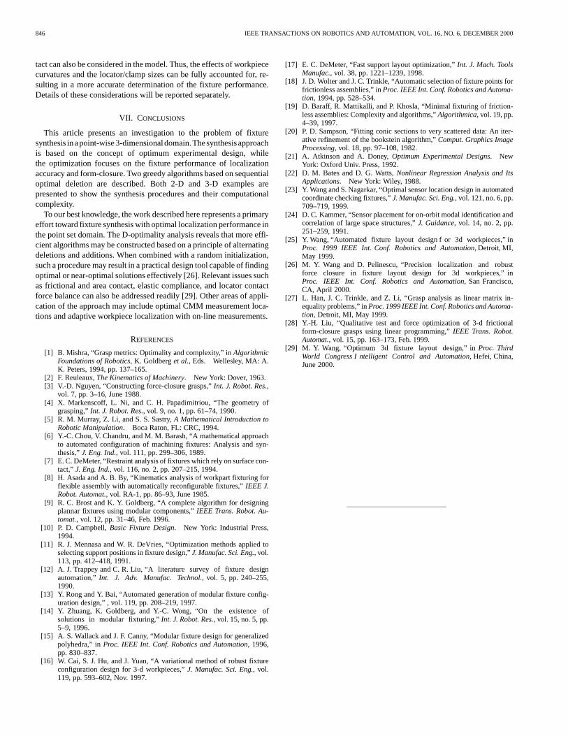
The first algorithm finds final six optimum locators among these can-didates as shown in Fig. 9. The values oflog(detMMM) are plotted inFig. 11. Based on the optimum locators, one has to find a clamp loca-tion among the remaining 1540 candidates to satisfy the form-closure
Fig. 8. An airfoil with 1546 candidate fixture locations.
Fig. 9. Six D-optimal locators obtained with the first algorithm.
condition. This is a linear search and it reveals that there exist only twoclamping locations possible for form-closure. This case illustrates the“bias” of the first algorithm. It results in a better set of D-optimal loca-tors, but it leaves with a limited potential for form-closure clamping.
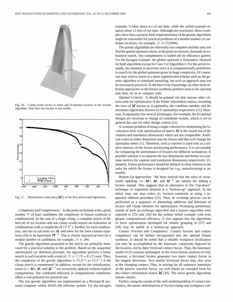
Next, the second algorithm is applied with a given clamp near themiddle of the airfoil. This algorithm finds the D-optimal locators withform-closure as shown in Fig. 10. The determinant values are plottedtogether with those of the first algorithm in Fig. 11 for comparison.As expected, the locators determined by the second algorithm is lessoptimal than those found by the first algorithm.
VI. DISCUSSIONS
With the above description of the synthesis approach, there are anumber of interesting aspects of the fixture synthesis algorithms worthyof further discussions.
IEEE TRANSACTIONS ON ROBOTICS AND AUTOMATION, VOL. 16, NO. 6, DECEMBER 2000 845
Fig. 10. Clamp (with circles at ends) and D-optimal locators of the secondalgorithm. Note that one locator is not visible.
Fig. 11. Determinant values (log(MMM)) of the first and second algorithms.
Complexity and Completeness:In the point set domain with a givennumberN of fixel candidates, the complexity of fixture synthesis iscombinatorial. In the case of a single clamp, a complete search of thebest set of six locators and one clamp would require an evaluation ofcombinations with a complexity ofO(N7). Further, for each combina-tion, one has to calculatedetMMM and solve for the form-closure equa-tions (16) or its equivalentMMM�1. This is clearly impractical even for amodest number of candidates, for example,N = 100.
The greedy algorithms presented in the article are primarily moti-vated for a practical solution to the problem. Based on the sequentialoptimization (or deletion) principle, the algorithms perform a linearsearch in each iteration with a total of(N +7)(N � 6)=2 cases. Thus,the complexity of the greedy algorithms isO(N2) or O(N3) if theclamp search is enumerated. In addition, except for the initialization,terms (detMMM ),MMM , andMMM�1 are recursively updated without explicitcomputations. The combined reduction in computational complexityoffers a real potential for practical use.
The two greedy algorithms are implemented on a Pentium-II per-sonal computer within MATLAB software system. For the hexagon
example, it takes about 4 s of run time, while the airfoil example re-quires about 12 min of run time. Although not conclusive, these exam-ples show that a purpose-built implementation of the greedy algorithmsmight be reasonable for practical problems of a modest number of can-didate locations, for example,N = O(1000).
The greedy algorithms are inherently not complete and they may notfind the global optimum which, in the point set domain, demands an ex-haustive search. The completeness is traded off for efficiency gained.For the hexagon example, the global optimum is fortunately obtainedfor both algorithms except for Case 2 of Algorithm 2. For the airfoil ex-ample, the situation is uncertain since it is computationally prohibitiveto search for the global optimum given its huge complexity. Of course,one may wish to resort to a more sophisticated scheme such as the ge-netic algorithm or simulated annealing, but such an approach may notbe necessarily practical. To the best of our knowledge, no other more ef-ficient approaches to the fixture synthesis problem seem to be reportedand, thus, for us to compare with.
Optimal Criteria: It should be pointed out that various other cri-teria exist for optimization of the Fisher information matrix, includingthe trace ofMMM known as A-optimality, the condition number, and theminimum eigenvalue (known as E-optimality) respectively [21]. How-ever, D-optimality has several advantages. For example, the D-optimaldesigns are invariant to change of coordinate system, which is not ingeneral the case for other design criteria [21].
A common problem of using a single criterion for minimizing the lo-calization error with optimization of matrixMMM is the mixed use of therotation and translation dimensions which are not comparable. Artifi-cial scales in either dimension may be chosen and they will change theoptimality metric [1]. Therefore, such a criterion is used only as a rel-ative measure of the fixture positioning performance. It is not suitablefor comparing the performance of fixtures for different workpieces. Apossible solution is to separate the two dimensions and define two sep-arate metrics for rotation and translation dimensions respectively. Ul-timately, fixture performance should be defined in close relation to thetasks for which the fixture is designed for, e.g., manufacturing or as-sembly.
Bottom-Up Approaches:We have noticed that the rules of recur-sively updating(detMMM), MMM , andMMM�1 are similar for adding alocator instead. This suggests that an alternative to the “top-down”technique of sequential deletion is a “bottom-up” approach. In theinitial step, one may select six locators randomly or using a se-quential addition procedure [25]. Then, anexchangeprocess can beperformed as a sequence of alternating additions and deletions oflocator and clamp elements for optimization. Promising preliminaryresults of such anexchange algorithmand aseesaw algorithmwerereported in [25] and [26] for the turbine airfoil example with evengreater computational efficiency. It also appears that the algorithmsof force optimization developed for robotic grasping in [27] and[28] may be useful in a bottom-up approach.
Contact Friction and Compliance:Contact friction and contactcompliance can be further incorporated into the optimal fixturesynthesis. It should be noted that a reliable workpiece localizationcan only be accomplished by the kinematic constraints imposed bythe locators, not by their frictional contact forces. Thus, the kinematicmodel of (5) remains unchanged. In the form-closure analysis of (16),however, a frictional locator generates two more contact forces inthe tangent directions. Two similar frictional forces may also ariseat the clamping contact. Thus, in solving for all unknown intensitiesof the passive reaction forces, we will obtain an extended form forthe contact information matrixMMM [29]. The entire greedy algorithmsremain similar.
Further, using the results of the well-studied problem of contact me-chanics, the elastic deformations of locator/clamp and workpiece con-
846 IEEE TRANSACTIONS ON ROBOTICS AND AUTOMATION, VOL. 16, NO. 6, DECEMBER 2000
tact can also be considered in the model. Thus, the effects of workpiececurvatures and the locator/clamp sizes can be fully accounted for, re-sulting in a more accurate determination of the fixture performance.Details of these considerations will be reported separately.
VII. CONCLUSIONS
This article presents an investigation to the problem of fixturesynthesis inapoint-wise3-dimensionaldomain.Thesynthesisapproachis based on the concept of optimum experimental design, whilethe optimization focuses on the fixture performance of localizationaccuracy and form-closure. Two greedy algorithms based on sequentialoptimal deletion are described. Both 2-D and 3-D examples arepresented to show the synthesis procedures and their computationalcomplexity.
To our best knowledge, the work described here represents a primaryeffort toward fixture synthesis with optimal localization performance inthe point set domain. The D-optimality analysis reveals that more effi-cient algorithms may be constructed based on a principle of alternatingdeletions and additions. When combined with a random initialization,such a procedure may result in a practical design tool capable of findingoptimal or near-optimal solutions effectively [26]. Relevant issues suchas frictional and area contact, elastic compliance, and locator contactforce balance can also be addressed readily [29]. Other areas of appli-cation of the approach may include optimal CMM measurement loca-tions and adaptive workpiece localization with on-line measurements.
REFERENCES
[1] B. Mishra, “Grasp metrics: Optimality and complexity,” inAlgorithmicFoundations of Robotics, K. Goldberget al., Eds. Wellesley, MA: A.K. Peters, 1994, pp. 137–165.
[2] F. Reuleaux,The Kinematics of Machinery. New York: Dover, 1963.[3] V.-D. Nguyen, “Constructing force-closure grasps,”Int. J. Robot. Res.,
vol. 7, pp. 3–16, June 1988.[4] X. Markenscoff, L. Ni, and C. H. Papadimitriou, “The geometry of
grasping,”Int. J. Robot. Res., vol. 9, no. 1, pp. 61–74, 1990.[5] R. M. Murray, Z. Li, and S. S. Sastry,A Mathematical Introduction to
Robotic Manipulation. Boca Raton, FL: CRC, 1994.[6] Y.-C. Chou, V. Chandru, and M. M. Barash, “A mathematical approach
to automated configuration of machining fixtures: Analysis and syn-thesis,”J. Eng. Ind., vol. 111, pp. 299–306, 1989.
[7] E. C. DeMeter, “Restraint analysis of fixtures which rely on surface con-tact,” J. Eng. Ind., vol. 116, no. 2, pp. 207–215, 1994.
[8] H. Asada and A. B. By, “Kinematics analysis of workpart fixturing forflexible assembly with automatically reconfigurable fixtures,”IEEE J.Robot. Automat., vol. RA-1, pp. 86–93, June 1985.
[9] R. C. Brost and K. Y. Goldberg, “A complete algorithm for designingplannar fixtures using modular components,”IEEE Trans. Robot. Au-tomat., vol. 12, pp. 31–46, Feb. 1996.
[10] P. D. Campbell,Basic Fixture Design. New York: Industrial Press,1994.
[11] R. J. Mennasa and W. R. DeVries, “Optimization methods applied toselecting support positions in fixture design,”J. Manufac. Sci. Eng., vol.113, pp. 412–418, 1991.
[12] A. J. Trappey and C. R. Liu, “A literature survey of fixture designautomation,”Int. J. Adv. Manufac. Technol., vol. 5, pp. 240–255,1990.
[13] Y. Rong and Y. Bai, “Automated generation of modular fixture config-uration design,” , vol. 119, pp. 208–219, 1997.
[14] Y. Zhuang, K. Goldberg, and Y.-C. Wong, “On the existence ofsolutions in modular fixturing,”Int. J. Robot. Res., vol. 15, no. 5, pp.5–9, 1996.
[15] A. S. Wallack and J. F. Canny, “Modular fixture design for generalizedpolyhedra,” inProc. IEEE Int. Conf. Robotics and Automation, 1996,pp. 830–837.
[16] W. Cai, S. J. Hu, and J. Yuan, “A variational method of robust fixtureconfiguration design for 3-d workpieces,”J. Manufac. Sci. Eng., vol.119, pp. 593–602, Nov. 1997.
[17] E. C. DeMeter, “Fast support layout optimization,”Int. J. Mach. ToolsManufac., vol. 38, pp. 1221–1239, 1998.
[18] J. D. Wolter and J. C. Trinkle, “Automatic selection of fixture points forfrictionless assemblies,” inProc. IEEE Int. Conf. Robotics and Automa-tion, 1994, pp. 528–534.
[19] D. Baraff, R. Mattikalli, and P. Khosla, “Minimal fixturing of friction-less assemblies: Complexity and algorithms,”Algorithmica, vol. 19, pp.4–39, 1997.
[20] P. D. Sampson, “Fitting conic sections to very scattered data: An iter-ative refinement of the bookstein algorithm,”Comput. Graphics ImageProcessing, vol. 18, pp. 97–108, 1982.
[21] A. Atkinson and A. Doney,Optimum Experimental Designs. NewYork: Oxford Univ. Press, 1992.
[22] D. M. Bates and D. G. Watts,Nonlinear Regression Analysis and ItsApplications. New York: Wiley, 1988.
[23] Y. Wang and S. Nagarkar, “Optimal sensor location design in automatedcoordinate checking fixtures,”J. Manufac. Sci. Eng., vol. 121, no. 6, pp.709–719, 1999.
[24] D. C. Kammer, “Sensor placement for on-orbit modal identification andcorrelation of large space structures,”J. Guidance, vol. 14, no. 2, pp.251–259, 1991.
[25] Y. Wang, “Automated fixture layout design f or 3d workpieces,” inProc. 1999 IEEE Int. Conf. Robotics and Automation, Detroit, MI,May 1999.
[26] M. Y. Wang and D. Pelinescu, “Precision localization and robustforce closure in fixture layout design for 3d workpieces,” inProc. IEEE Int. Conf. Robotics and Automation, San Francisco,CA, April 2000.
[27] L. Han, J. C. Trinkle, and Z. Li, “Grasp analysis as linear matrix in-equality problems,” inProc. 1999 IEEE Int. Conf. Robotics and Automa-tion, Detroit, MI, May 1999.
[28] Y.-H. Liu, “Qualitative test and force optimization of 3-d frictionalform-closure grasps using linear programming,”IEEE Trans. Robot.Automat., vol. 15, pp. 163–173, Feb. 1999.
[29] M. Y. Wang, “Optimum 3d fixture layout design,” inProc. ThirdWorld Congress I ntelligent Control and Automation, Hefei, China,June 2000.