an object-oriented xml schema for the mip joint … · to avoid diverging and incompatible exchange...
TRANSCRIPT

2006 CCRTS
Command and Control Research and Technology Symposium
The State of the Art and the State of the Practice
June 20 – 22, 2006
San Diego, CA
Topic: C2 Experimentation
Title: An Object-Oriented XML Schema for theMIP Joint Command, Control, and ConsultationInformation Exchange Data Model
Authors:Name: Michael GerzOrganization: FGAN/FKIEAddress: Neuenahrer Straße 20
53343 Wachtberg-Werthhoven, GermanyPhone: +49 228 9435 414Fax: +49 228 9435 685E-Mail: [email protected]
Name: Francisco LoaizaOrganization: Institute for Defense AnalysesAddress: 4850 Mark Center Drive,
Alexandria, VA, 22311, United StatesE-Mail: [email protected]
Name: Erik ChaumOrganization: Defense Modeling and Simulation OfficeAddress: 1901 North Beauregard Street, Suite 500,
Alexandria, VA, 22311, United StatesE-Mail: [email protected]
An Object-Oriented XML Schema for the
MIP Joint Command, Control, and Consultation
Information Exchange Data Model
Michael Gerz, Francisco Loaiza, Erik Chaum
Semantic interoperability among command and control information systems is crit-ical to information sharing and proper automated processing. To improve multina-tional combined and joint mission capabilities, the Multilateral Interoperability Pro-gramme (MIP) has defined the Joint Command, Control, and Consultation Informa-tion Exchange Data Model (JC3IEDM), which is gaining wide acceptance beyondthe MIP community.
In this paper, we present a reference XML schema definition (XSD) that hasbecome an integral part of the JC3IEDM 3.0 specification. It provides an object-oriented view on the data model and aims at simplifying and accelerating the adop-tion of the MIP data model in service-oriented architectures and web applicationdevelopment.
We provide the use cases and design principles that have lead to this XSD. More-over, we show how this type of XML schema can be obtained in an automated wayfrom any relational schema in third normal form by applying only structural and syn-tactic transformative rules. The application of the XSD is demonstrated by instanceXML documents that describe an operational scenario.
Keywords: XML, XML Schema, XSD, Multilateral Interoperability Programme,MIP, JC3IEDM, STANAG 5525
1. Introduction
Semantic interoperability among command and control information systems (C2IS) is critical toinformation sharing and effective automated processing. To improve multinational combined andjoint mission capabilities, a voluntary multinational community of interest (COI) has developedand worked over many years to address the fundamentally difficult task of building communityconsensus and semantic standards for command and control information exchange. This work isbeing done by the Multilateral Interoperability Programme (MIP; http://www.MIP-site.org)which is currently comprised of 25 nations, the North Atlantic Treaty Organization (NATO), andthe US Allied Command Transformation (ACT). The MIP documents its conceptual and seman-tic consensus in an entity-relationship data model, the most recent of which is the Joint Com-mand, Control, and Consultation Information Exchange Data Model (JC3IEDM; see MIP, 2005).The JC3IEDM and its predecessor, the C2IEDM, are gaining wide acceptance beyond the MIPcommunity as a foundational core component for command and control semantic interoperabil-ity. The JC3IEDM edition 3.0 was published by the MIP in December 2005. Its adoption
1
1. Introduction
VERTICAL-DISTANCE
REFERENCE
GROUP-CHARACTERISTIC
COORDINATE-SYSTEM
AFFILIATIONADDRESS
ACTION
CONTEXT
OBJECT-ITEMOBJECT-TYPE
LOCATION
REPORTING-DATA
RULE-OF-ENGAGEMENT
CAPABILITY
CANDIDATE-TARGET-LIST
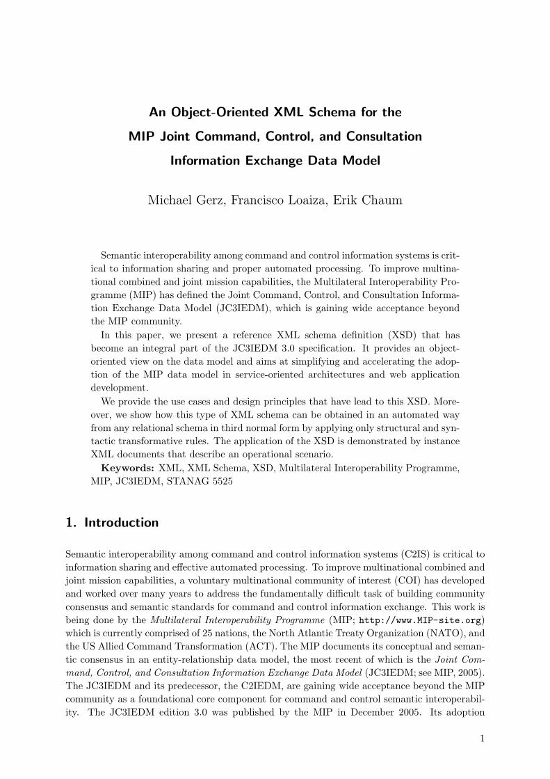
Figure 1: JC3IEDM Independent Entities (IDEF1X Notation)
by NATO, and the ongoing NATO ratification as STANAG 5525, will strongly influence thedevelopment of future C2ISs.
The JC3IEDM has a very rich capability to express both operational and tactical context. Muchmore than a simple tactical picture, the MIP’s operational analysis process has defined a setof information exchange requirements that support the commander across a spectrum of typesof operations and activities (e.g., planning, coordination, execution, observing, and decisionmaking). Figure 1 shows a high-level independent entity-relationship view of the JC3IEDM.The C2IEDM and JC3IEDM have the essential common characteristic of being generic (i.e., notderived directly from system-specific implementations) and extensible (i.e., suitable as a core towhich functional extensions can be added).
This last point is critical because without a shared core set of concepts and semantics each func-tional community of interest will build unique incompatible representations of the battlespace.This results in higher costs to develop and integrate systems and services and results in limitedinformation exchange and automated processing capabilities due to the limitations of media-tion (i.e., mapping or translating). If mediation produces a complete and precisely equivalentrepresentation then the mapping was completely syntactic (i.e., the exact same representationwas developed twice – a low probability event). Most often this is not the case and mappingand translation are incomplete, imprecise, contextually loose, and produce an ambiguous result.This limits interoperability, the users’ trust and understanding of the information being shared,and in the end operational effectiveness.
Recently, many national and international projects have been initiated to explore the benefitsof XML technologies and Web Services in the C2 area. Exposing unique semantics in XML doesnot address the fundamental limitations of mediation. While XML simplifies the processing ofdocuments by means of a uniform syntax, there is still a need to have a common understandingof the information to be exchanged, i.e., the set, and structure, of the XML elements used forinformation exchange and their semantics have to be defined.
2

Information models are essentially specifications of semantics and syntax. Thus, it makes senseto use the JC3IEDM as a multinational, system-independent standard for XML C2 semantics.To avoid diverging and incompatible exchange formats in each individual project, there shouldbe reference XML schema definitions (XSDs) based on the data structures contained in theJC3IEDM. The MIP community has addressed this demand by developing two standardizedXML schemas.1
The first reference MIP XML schema, namely the RDBMS XSD, reflects the relational view ofthe JC3IEDM. It addresses information exchanges among relational databases whose physicalschemas are based on the JC3IEDM specifications. The design of the second reference MIPschema has been motivated by the perceived need to support Web Service (WS) applicationswithin the C2 community. It provides an object-oriented view of the data model and aims atsimplifying and accelerating the adoption of the MIP data model in service-oriented architecturesand web application development. The object-oriented reference MIP XML schema (WS/OOXSD) does not make any assumptions on the physical storage of operational data and yet allowschecking many of the referential integrity constraints of the JC3IEDM during instance XMLdocument validation. These features make the WS/OO XSD very attractive to applicationsthat do not necessarily rely on, or need a JC3IEDM-compliant relational database (e.g., forpersistence), or which do but desire to present an object-oriented exchange service.
It should be noted that the design rationale for both XML schemas and their associated technicalartifacts are now part of the official JC3IEDM 3.0 specification.
In this paper, we present the object-oriented reference MIP XML schema. In section 2, weprovide the use cases and requirements that have lead to the WS/OO XSD. In section 3, weshow how this type of XSD can be obtained from any relational schema in third normal formby applying only structural and syntactic transformative rules. The generality of this approachenables the model and XSD to be extended by functional communities. The application of theWS/OO XSD is demonstrated by an operational scenario in which a contingency plan for acomposed military obstacle is generated, and updated (section 4 and appendix A). Based on theexample, we show that the WS/OO XML schema is not restricted to one particular informationexchange mechanism. In section 5, we describe a tool kit that allows, in an automatic way,deriving the XSD and corresponding Java classes. The paper closes with a summary in section 6.
2. XML Use Cases and Schema Requirements
XML is a universal information exchange syntax with wide acceptance in industry. It can beused in various types of applications and use cases. In the context of MIP, six potential usecases were identified:
• Data exchange:
– Web Services (e.g., exchange of business objects).
– Exchange with non-MIP databases.
– MIP XML Exchange Mechanism (exchange among MIP databases via XML).
• Transformation services:1The results presented in this paper have been developed within the XML Working Party of the MIP. Apart from
the authors, the members of the XML WP are (in alphabetical order): Fred Burkley (US, Naval UnderseaWarfare Center), Gerald Ortner (NHQC3S, NDA), and Cecilia Unell (SE, Combitech AB).
3

2. XML Use Cases and Schema Requirements
– Supporting tactical communications interfaces, e.g., ADatP-3 or USMTF (effectivelyalmost always lossy).
– Mediation between different versions of the MIP data model.
– Export to various output/presentation formats, e.g., STANAG 5500-conformant mes-sages or HTML.
It is recognized that an optimal schema design can only be achieved in the context of a specificset of detailed requirements. For each use case described above, we can derive different require-ments on the XML schema. The requirements are partially contradictory, i.e., no single XMLschema fits all purposes equally well. For instance, information exchange between MIP databasesand mediation between different data model versions requires an XML schema that facilitateseasy integration into MIP-compliant systems and a simple mapping to the JC3IEDM relationaldatabase schema. These requirements are met by the MIP RDBMS XSD. For information ex-change via web services, the focus shifts to simple integration into object-oriented applications.Here, the strict technical adherence to a relational data model may be considered as a hindranceto efficient data processing. The WS/OO XML schema addresses this requirement.
In the following, we discuss three factors from which we derive requirements on the XML schemadesign. These factors are (a) the type of sender/receiver of the XML message, (b) the informationexchange mechanism, and (c) existing XML standards.
2.1. Requirements Derived from Sender/Receiver
The sender/receiver of an XML message may either be a person, a generic XML viewer (e.g., aweb browser), or a C2 information system. In the latter case, we can distinguish between systemsthat maintain a JC3IEDM-compliant relational database and systems that use a proprietary datamodel internally and make their data persistent in an arbitrary way, e.g., in an object-orienteddata base.
Systems that do not store their data in a MIP-compliant RDBMS can greatly benefit from anXML schema that abstracts from the relational data model. The same holds for systems thatuse the JC3IEDM data base schema but for which the MIP Data Exchange Mechanism (DEM)is replaced or complemented by web services.
To support modern software development, an XML schema with an object-oriented view on theMIP IEDM is highly desirable. Developers will also require that code fragments, which complywith the XML schema (e.g., Java classes), can be generated efficiently.
If there is no back-end RDBMS to enforce the MIP data model semantics (in particular referentialintegrity), the XML schema should include semantic constraints for domain values, documentconsistency (no orphan objects), and, ideally, the JC3IEDM business rules. These can be checkedduring instance XML document validation.
In a mixed MIP/non-MIP environment, syntactic and semantic transformations are inevitable.The combination of XSL-T and an implementation-neutral object-oriented schema provides atechnically mature application path for gateways that mediate between the different worlds.
When the sender/receiver is a person, an XML tag naming convention must ensure ease ofreadability and comprehension. Software developers working with the XML documents andassociated code classes will also benefit from such naming conventions.
4

2.2. Requirements Derived from Information Exchange Mechanism
2.2. Requirements Derived from Information Exchange Mechanism
There are several possible ways in which systems and/or people may exchange information. Wedistinguish between three different information exchange mechanisms:
• Message-based communication
• Replication-based communication
• Query-based communication
In the first case, instance XML documents describe referentially complete, self-contained mes-sages.2 For message-based communication, the XSD must ensure referential integrity within asingle XML document according to the rules of the data model. Moreover, the XSD for the MIPIEDM must be generic in that it must be possible to tailor it to specific business object XSDs.
In a replication-based scenario, an initial data load is exchanged and then incremental informa-tion updates are transmitted (push technology). For instance, only status updates may be sent,once the corresponding unit has been transmitted.
When a receiver queries data from a provider (pull technology), the query results may notnecessarily be complete either. For example, a web client requests information on what unitsare in a given geographic region. In response, the client receives a report that mentions unitBravo is at location Alpha as of time Tango. The user subsequently wants to know Bravo’scurrent location. Thus, the web client must be able to refer to Bravo by means of a ’key’ (e.g.,object identifier, URL, or similar) and the web service must be able to provide a position reportupdate on request, which only contains the information that has changed. There may also becases in which the query result contains references to objects that are not yet known to theweb client. This just-in-time, interactive, pull for relevant data is consistent with web servicesconcepts and complementary to the traditional MIP smart push architecture.
The referential integrity and completeness required by the MIP IEDM has implications for thedesign of XML schemas and associated web services. The latter two use cases require a referencemechanism such that instance documents can refer to external information. However, one neednot necessarily retain all of the synthetic keys of the MIP data model for that purpose. Thereferential integrity constraints in the XSD that hold for message-based communication must berelaxed in replication- and query-based use cases. It is the responsibility of the web service andclient – not of the XSD! – to ensure that external references are used appropriately.
2.3. Requirements Derived from XML Standards
In order to facilitate the validation of XML documents, the XML document format must beformalized by means of an XML schema. The schema itself is specified in a schema language.There are many different schema languages available with varying expressiveness and complexity.An overview of existing schema languages is given by van der Vlist (2001). Currently, the mostprominent schema language is XML Schema (W3C, 2004a,b,c). It is the one adopted for theMIP WS/OO XML schema.3 It is standardized by the World Wide Web Consortium (W3C)
2This approach has been adopted by the MIP MEM and the ADatP-3 community before. However, the defi-nition of hundreds of message text formats (MTF) resulted in a variety of different representations for basicinformation like time and date. Self-contained XML messages based on the JC3IEDM resolve the problem asthe entities of the MIP IEDM define standard data elements (SDE).
3In the following, the term XML Schema is written in small capitals if it refers to the specification languageitself. Otherwise, it refers to the concrete WS/OO XML schema.
5

3. XML Schema Design
and supported by virtually all XML tool vendors. The W3C XML Schema is based on anobject-oriented model, i.e., it allows defining types and using inheritance.
Fundamental to achieving multinational and joint network-enabled capability (net-centric ornetwork-enabled operations) is a common structure and language for information handling. XMLdoes not support interoperability automatically. Today, there are hundreds of XML vocabularies;a fact which may account in part for the limited improvement in semantic interoperability despitethe commonality of syntax. Therefore, while XML provides new tools for improving point-to-point translations, the long-term objective and big win comes through semantic harmonization.
To that effect, Naming and Design Rules (NDR) are being developed at the international,multinational and national levels. Their intent is to facilitate the discovery and use of commondata elements (standardized XML vocabulary), and to provide additional rigor to the XMLstandards in order to maximize interoperability and enhance supportability. NDRs specifyvarious aspects of an XML schema: naming of XML elements and attributes, schema versioning,schema modularization, definition of namespaces, (restricted) use of XML Schema constructs,etc. NDRs are mainly concerned with the structure and reusability of XML schemas; they donot answer completely what instance XML documents should look like for a particular use case.
In the WS/OO XML schema, the Guidance for XML Naming and Design within NATO (GXND ;currently only in draft) was applied where practical. The GXND is based on two standards:ISO/IEC 11179 (Metadata Registries, MDR; see ISO/IEC, 2005) and ISO 15000-5 (Electronicbusiness eXtensible Markup Language, ebXML; see ISO, 2005).
3. XML Schema Design
Based on the requirements listed in the previous section, we have developed the reference MIPWS/OO XSD. Structures in instance XML documents conforming to the WS/OO XSD closelymatch the typical OO concepts, e.g., inheritance and navigability. In particular, the represen-tation of relationships and associations via nesting greatly simplifies the adoption of the MIPIEDM in object-oriented applications. To describe (potentially cyclic) graph structures in thetree-like XML notation, a simple mechanism for referencing objects is provided. Instance XMLdocuments exchanged in accordance with the WS/OO XSD do not prescribe any specific storageformat, i.e., the WS/OO XML schema abstracts from the underlying persistence mechanism.This matches with the notion of defining an XML exchange format. Developers are able tochoose any persistence framework, API, or tool, which simplifies integration.
The XML schema is fully automatically derivable from the MIP IDEF1X (see Wikipedia, 2006b)model by applying syntactic transformations only. In that way, the generation is independentfrom a particular version of the MIP data model. This approach ensures correctness and min-imizes XSD production and maintenance cost. If we had relied on the specific semantics of aparticular version of the MIP data model to drive the transformations, we would have had tocheck the mapping rules as the model changed over time. Moreover, transforms must be trace-able – the more we transform away from the relational model, the more difficult it becomes tospecify and apply the transformation rules and to prove their correctness.
The WS/OO XSD is primarily based on the logical view of the MIP JC3IEDM. The physicalview of the data model contains a few additional MIP DEM-specific attributes and is designedfor an RDBMS implementation. However, all types of web-services should be supportable bythe WS/OO XSD, which is more readily accomplished when basing the specification on thesemantics of the logical view of the MIP IEDM.
6

3.1. Naming Conventions
In this section, the mapping rules are described that are applied to the MIP data model in orderto produce the object-oriented XML schema. These rules create a faithful representation of themodel. The focus of the following description is on what instance XML documents look likerather than on the technical details of the XML schema definition. The WS/OO XSD comesalong with a tool set (see section 5), such that the whole transformation process – starting withthe MIP data model in ERwin XML format and ending with the XML schema files – is traceable.The WS/OO XSD and the tool set are available at the MIP web site and considered a normativepart of the reference MIP WS/OO XSD specification.
For a complete mapping, transformation rules must be defined for names, domains, entities,attributes, and relationships (including subtyping and associative entities). Moreover, the rootelement of XML documents must be specified. The mapping rules are described in detail inthe following subsections. The MIP XML Working Party worked through a process wherebyentity-relationship (ER) modeling constructs were interpreted into UML and then interpretedinto an XML design pattern.
3.1. Naming Conventions
To ensure consistency and reproducibility, naming conventions are needed for entities, attributes,and the root element visible in instance XML documents, as well as for simple types, codes, andentity types that only show up in the XML schema definition. Naming of domains, entity types,and attributes in XML is based on the logical view rather than on the physical view of theMIP data model. This enhances readability and comprehension. In accordance with the NATONaming Guidelines, the UpperCamelCase convention is used for naming XML elements andXML types, whereas the lowerCamelCase convention is used for naming XML attributes.
3.2. Domains
Domains in the ER model are mapped onto XML simple types. The latter are derived from thepre-defined XML Schema types integer, double, and string. Physical restrictions on JC3IEDMdomains, i.e., the number of digits for integers, the precision and scale of floating point num-bers, and the minimum/maximum length of character strings are reflected in the XSD. Whereavailable, specific range restrictions (e.g., maximum temperature or non-negative quantity) areregarded as well. The upper and lower boundary of numbers is modeled by the XML Schema
attributes minInclusive and maxInclusive. The minimum and maximum length of strings ismodeled by means of the attributes minLength and maxLength.
Codes are represented as strings that are restricted by enumeration. JC3IEDM code values arespecified as physical values rather than display values in an instance XML document. This ismotivated by efficiency with regard to bandwidth, software development and object persistency.The mapping from the physical values to display values is a matter of national language prefer-ence and can be realized easily by means of an XSL-T script. The display values documentedby the MIP data model (international English) are included as annotations in the XSD forconvenience.
3.3. Entities and Attributes
Entity types in the MIP IEDM are mapped onto complex types in the XML schema definition.In conformance with the NATO XML Naming and Design Rules, attributes in the ER model arespecified as XML elements, not XML attributes, exclusively. This simplified approach removes
7

3. XML Schema Design
Design PatternIDEF1X
A
a-id
a-some-attr-1
a-some-attr-2
a-some-attr-3 (FK)
UML
XML <A>
<OID>. . . </OID>
<SomeAttr1>. . . </SomeAttr1>
<SomeAttr2>. . . </SomeAttr2>
[relationships]
</A>
<ARef>
<OID>. . . </OID>
[relationships]
</ARef>
Figure 2: Entities and Attributes
the arbitrary or even semantic decision about when to use what. Accordingly, an entity isdescribed by an element with child elements for its attributes in an instance XML document(see figure 2).
Optionality of attributes in the MIP IEDM is maintained by means of the XML Schema
minOccurs attribute.
Non-key attributes are mapped to XML elements by applying the above-mentioned namingconventions. Whenever possible, the entity type name, which is added as a prefix for theattribute names in the logical view, is truncated. This rule conforms to the class and propertyconventions used in object-oriented programming, i.e., the meaning of an XML element is derivedfrom its context.
Primary and foreign key attributes (i.e., identifiers and indexes) are not mapped directly. In-stead, the transformation patterns for relationships (see next section) are applied.
Object Identifiers. In the WS/OO XSD, globally unique object identifiers (OIDs) replacethe synthetic primary keys of the MIP data model. The global uniqueness of OIDs simplifiesintegration into object-oriented applications. An OID is a sequence of characters that allows anapplication locating and managing (persistent) objects. In the context of the world-wide web, anOID may be a URI (Uniform Resource Identifier). In this case, the OID denotes a web addressthat can be used to refer and retrieve the object, and the closure of all IEDM objects forms alocalized semantic web of their own.
In the WS/OO XSD, OIDs are defined for all types that either correspond to independent entitytypes in the ER model or have list elements and thus need to be referable for future updates.Whether an XSD type has an OID is determined after applying the transformation patterns forrelationships and associations.
References. At any place in an instance XML document where it is possible to specify anentity with an OID (inline), it is also possible to specify a reference to that entity. Both optionsare included (a) to provide support for various instance document styles, (b) to handle graph
8

3.4. Transformation Rules for Relationships
Design PatternIDEF1X
A
a-id
B
a-id (FK)
UML
-bList[0..*] : B
A B
1 0..*
XML <A>
<BList>
<B>. . . </B> (inline)
<BRef> . . . </BRef> (by reference)
. . .
</BList>
</A>
Figure 3: Identifying Relationships
structures, and (c) to allow for both referentially complete and incremental update informationexchange methods.
References are indicated by adding suffix Ref to the name of the XML element (e.g., UnitRefor ReportingOrganisationRef ). Beside its OID, an entity reference has neither elements (entityattributes) of simple type nor of code type. However, an entity reference can be used to describe anew relationship of the referred entity with another one. For instance, a new OrganisationStatusmay be specified inside a UnitRef element (see next section for the modeling of relationships).
XML binding tools/frameworks like JAXB (Sun Developer Network, 2006), Castor (exo-lab.org, 2006), or Commons Betwixt (Jakarta Project, 2006) use XML’s ID/IDREF mecha-nism to serialize graph structures. However, please note that ID/IDREF can only be used asa referencing mechanism for referentially complete documents but not when exchanging incre-mental updates.
The XML schema definition is available in two variants: with and without identity constraints,i.e., checks for internal referential completeness. The WS/OO XSD that includes the identityconstraints enforces a corresponding entity definition for every reference. These entities must bedefined by a child element of the root element. The identity constraints are specified in a waythat ensures type-safe referential integrity of instance XML documents (ID/IDREF would notprovide type-safety). The constraints are defined as part of the XML root element definition(see section 3.5).
3.4. Transformation Rules for Relationships
3.4.1. Identifying and Non-Identifying Relationships
In IDEF1X, the modeling technique and notation used for the MIP IEDM, there are two basictypes of relationships: identifying and non-identifying relationships. They correspond to one-to-one and one-to-many associations between classes in UML where the associations may benavigable in either both directions or one direction. In most cases, a link is established from theparent to its child only.
An identifying relationship means that the child cannot be uniquely identified without the parent.For example, an OBJECT-ITEM-STATUS cannot exist without its OBJECT-ITEM. In an ER
9

3. XML Schema Design
Design PatternIDEF1X
A
b-id (FK)
B
b-id
UML
-b[0..1] : B
A B
* 0..1
XML <A>
<B>. . . </B> (inline)
</A>
or
<A>
<BRef> . . . </BRef> (by reference)
</A>
Figure 4: Non-Identifying Relationships
model, an identifying relationship is modeled by a primary key in the child that is also a foreignkey referring to the parent.
Identifying relationships are modeled in the WS/OO XSD according to the design pattern shownin figure 3: A new list element, called BList, is embedded into the parent entity, which againencompasses multiple B elements. If possible, the name of the parent is stripped from thenames of the elements. Example: The one-to-many relationship between an OBJECT -ITEMand an OBJECT -ITEM-STATUS is modeled in XML by StatusList and Status elements. (Note:strictly speaking List elements are not required but are included for clarity).
Depending on the cardinality of the relationship (zero-one-or-more, one-or-more, zero-or-one),the list element may be absent or contain one or more definitions of child entity B. The cardinalityof identifying relationships is ensured by adding minOccurs and maxOccurs attributes to thecorresponding definitions in the XSD.
Please note that List elements may also occur within entity references (e.g., within ObjectItem-Ref ). This allows adding information on new relationships to entities that have been defined/ex-changed before. In entity references, minOccurs is always set to 0.
A non-identifying relationship is one where the child can be identified independently of theparent. For instance, an Organisation can exist independently from a ReportingData that refersto it as the reporting organization. The transformation of non-identifying relationships is shownin figure 4. The optionality (null allowed vs. no null) of non-identifying relationships is expressedby minOccurs attributes in the WS/OO XSD.
3.4.2. Subtype Relationships
In instance XML documents, subtyping relationships are represented by embedding all the at-tributes from a subtype hierarchy within the tag corresponding to the leaf entity (see figure 5).In the WS/OO XML schema definition, the complex type for the sub-entity is derived fromthe complex type for the super entity by means of the extension method of XML Schema.Functional COIs may tailor individual types either by further extension or by restriction.
In IDEF1X, the subtype is indicated by a discriminator code (category code) in the super type.In WS/OO instance XML documents, category codes do not have to be specified in general, as
10

3.4. Transformation Rules for Relationships
Design PatternIDEF1X
a-category-code
A
a-id
a-category-code
B
b-id (FK)
UMLA B
XML <B>
<Attr1 of A>. . . </Attr1 of A>
<Attr2 of A>. . . </Attr2 of A>
. . .
<Attr1 of B>. . . </Attr1 of B>
. . .
</B>
Figure 5: Subtype Relationships
they are implied by the subtype tag itself. However, in the case of incomplete subtyping, thediscriminator code must be specified if it does not correspond to one of the existing sub-entities(this holds for codes like NOS – Not Otherwise Specified).
3.4.3. Many-to-Many Relationships – Associative Entities
In relational models, a many-to-many relationship between two entities A and B is expressed byan associative entity A-B-ASSOC that is the child of both A and B via identifying relationships.In the MIP IEDM, all many-to-many-relationships are binary. Nevertheless, we can distinguishthree cases:
• Associative entities with only primary key attributes
• Associative entities with non-primary key attributes
• Double-associative entities
An associative entity with only primary key (PK) attributes is equivalent in UML to a simpleassociation between the two parent classes. Each parent may have a list of references to instancesof the other class. This view is also reflected in the design pattern given in figure 6. Associativeentities without non-PK attributes are not mapped onto the XML schema. The relationshipsfrom parent A to A-B-ASSOC and from parent B to A-B-ASSOC are mapped as if they wereidentifying relationships from A to B and vice versa. Note that since there is no preferreddirection in the association, either entity can be nested inside the other in XML.
If the associative entity has non-primary key attributes, it corresponds in UML to an attributedassociation with an association class that contains the attributes. There are several ways torepresent such many-to-many relationships in XML (see, e.g., Williams, 2002). For the WS/OOXSD, a design pattern is applied that allows embedding the association into either parent (seefigure 7). For that purpose a list element (ABAssocInAList) is introduced. It contains tuplesconsisting of the associated second parent of type B and the associative entity that holds theassociation attributes.
The ability to describe associations by nesting rather than by a top-level element avoids informa-tion scattering throughout XML documents and enhances readability. Moreover, the WS/OO
11

3. XML Schema Design
Design PatternIDEF1X
B
b-id
A
a-id
A-B-ASSOC
a-id (FK)
b-id (FK)
UML
-bList[0..*] : B
A
-aList[0..*] : A
B
0..* 0..*
XML <A>
<BList>
<B>. . . </B> (inline)
<BRef>. . . </BRef> (by ref .)
. . .
</BList>
</A>
<B>
<AList>
<A>. . . </A> (inline)
<ARef>. . . </ARef> (by ref .)
. . .
</AList>
</B>
Figure 6: Associative Entities With Only PK Attributes
Design PatternIDEF1X
B
b-id
A
a-id
A-B-ASSOC
a-id (FK)
b-id (FK)
some-attr
UML
A B
A-B-ASSOC
* *
XML <A>
<ABAssocInAList>
<ABAssocInA>
<B>. . . </B>
<ABAssoc>. . . </ABAssoc>
</ABAssocInA>
</ABAssocInAList>
</A>
<ABAssoc>
<SomeAttr> . . . </SomeAttr>
. . .
</ABAssoc>
<B>
<ABAssocInBList>
<ABAssocInB>
<A>. . . </A>
<ABAssoc>. . . </ABAssoc>
</ABAssocInB>
</ABAssocInBList>
</A>
Figure 7: Associative Entities With Non-PK Attributes
12

3.5. XML Root Element
Design PatternIDEF1X
A
a-id
A-ASSOC
subject-a-id (FK)
object-a-id (FK)
some-attr
UMLA A-ASSOC
*
*
XML <A>
<AAssocInSubjectAList>
<AAssocInSubjectA>
<ObjectA>. . . </ObjectA>
<AAssoc>. . . </AAssoc>
</AAssocInSubjectA>
</AAssocInSubjectAList>
<AAssocInObjectAList>
<AAssocInObjectA>
<SubjectA>. . . </SubjectA>
<AAssoc>. . . </AAssoc>
</AAssocInObjectA>
</AAssocInObjectAList>
</A>
Figure 8: Double-Associative Entities
XSD supports object-to-association reasoning rather than association-to-object reasoning. Thisis considered as an important prerequisite for the compact definition of community-specific mes-sage formats that are derived from the generic XSD by tailoring.
It should be noted that the representation of associations in XML documents may differ fromthe internal representation in applications. For instance, the XML parser mentioned in section 5generates Java objects that support navigability in either directions (A → ABAssoc → B andB →ABAssoc → A).
There are also associations in which both relationships come from the same entity type. Thegeneric syntactic transformations for such associations are similar to the transformations forassociative entities with non-PK attributes given above. The only difference is that the elementnames include generic role names for the associated entities (see figure 8). Subject and Objectare used as (model-independent) role names. The suffixes are necessary, because in an XMLdocument the object may be embedded in the subject and vice versa.
3.5. XML Root Element
The root XML tag is equivalent to the model name in capital letters (<JC3IEDM>). Thedistinction between different model versions is made by means of the name space, whose URN,among others, incorporates the model version number.
The root XML element has an arbitrary number of unordered XML entity definitions as childelements. The names of the child elements are identical to the names of the corresponding entitytypes (e.g., Unit or ReportingDataAbsoluteTiming).
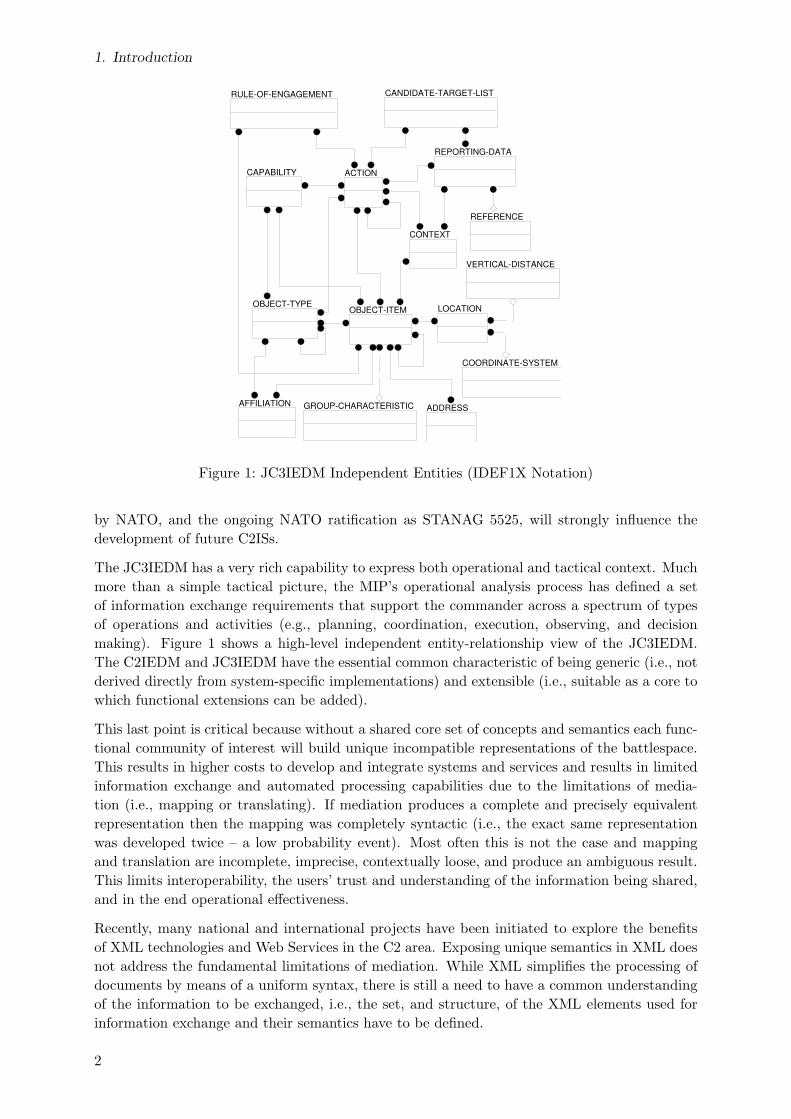
Each child must have a non-abstract and referable type. Non-abstract entity types do not havea subtype. For instance, ObjectItem is abstract whereas MinefieldLand is not. (In case ofincomplete subtyping, the super type can be regarded as non-abstract as well). Referable entitytypes have an object identifier (OID) attribute. An instance XML document with five top-levelentity definitions is shown in listing 1 on page 15.
13

4. XML Example
Yukon River
West Minefield East MinefieldWhite Horse
Bridge
Obstacle Alpha
S
N
Figure 9: Obstacle Alpha
4. XML Example
In the following, the use of the object-oriented XML schema is illustrated by the operationalscenario described in chapter 9.6 of the JC3IEDM main document (MIP, 2005, p. 246). Forconvenience, it is recapitulated in section 4.1. The modeling of the vignette by means of theJC3IEDM is described in section 4.2. Excerpts from the corresponding instance XML documentsare explained in section 4.3. For the complete documents, please see appendix A.
4.1. Operational Scenario
The JC3IEDM main document defines an operational scenario in which the 1st Canadian Brigadeis located near a bridge across the Yukon River. Its contingency plan is to use this bridge aspart of a larger military obstacle, called Obstacle Alpha:
”The White Horse Bridge across the Yukon River initially serves as a passage between twominefields located on the north side of the river, one on each side of the bridge. [...] If theunits of the joint task force that are now deployed on the north side of the river need towithdraw, the bridge will be demolished to become part of the main obstacle.” (MIP, 2005,p. 246)
The operational picture is shown in figure 9.
During the hostilities, the 1st CA Brigade is attacked and the contingency plan is put intoaction. The complete course of actions is as follows:
Reporting Time Action
22 Oct 2003, 10:30 1 CA Brigade creates the contingency plan to set up ObstacleAlpha which consists of the two minefields and the bridge tobe demolished.
02 Nov 2003, 09:49 Minefield West is laid and activated.03 Nov 2003, 15:42 Minefield East is laid and activated.03 Nov 2003, 17:10 The White Horse Bridge is prepared for demolition.07 Nov 2003, 08:10 The brigade elements north of the river cross to the south.
The bridge is demolished and Obstacle Alpha becomesoperational in its entirety.
4.2. JC3IEDM Modeling
In the JC3IEDM, the two minefields are modeled by means of entity type MINEFIELD-LAND.The White Horse Bridge is an instance of entity type BRIDGE and Obstacle Alpha is aMILITARY-OBSTACLE.
14
4.3. Instance XML Documents
1 <?xml version=”1.0” encoding=”UTF−8”?>2 <JC3IEDM xmlns=”urn:int:nato:standard:mip:jc3iedm3.0:oo:1.3”
xmlns:xsi=”http://www.w3.org/2001/XMLSchema−instance”xsi:schemaLocation=”urn:int:nato:standard:mip:jc3iedm3.0:oo:1.3..\..\schema\JC3IEDMSchemaWithConstraints.xsd”>
3 <MinefieldLand>4 <OID>OI1</OID>5 <NameText>West Minefield</NameText>6 ...7 <LengthDimension>300</LengthDimension>8 <WidthDimension>105</WidthDimension>9 <IdentificationText>Minefield West</IdentificationText>
10 <MineSpacingDimension>10</MineSpacingDimension>11 <DepthPlacementCode>MIXED</DepthPlacementCode>12 <FunctionCode>NUISNC</FunctionCode>13 <PatternCode>REGTHK</PatternCode>14 <PersistenceCode>REMOTE</PersistenceCode>15 <StoppingPowerCode>MEDIUM</StoppingPowerCode>16 </MinefieldLand>17 <MinefieldLand>18 <OID>OI2</OID>19 <NameText>East Minefield</NameText>20 ...21 </MinefieldLand>22 <Bridge>23 <OID>OI3</OID>24 <NameText>White Horse Bridge</NameText>25 ...26 </Bridge>27 <MilitaryObstacle>28 <OID>OI4</OID>29 <NameText>Obstacle Alpha</NameText>30 ...31 </MilitaryObstacle>32 <ReportingDataAbsoluteTiming>33 <OID>RPTD705</OID>34 ...35 </ReportingDataAbsoluteTiming>36 ...37 </JC3IEDM>
Listing 1: Top-level elements
Since all entities are facilities, their statuses are described by means of entity type FACILITY-STATUS. Both the White Horse Bridge and Obstacle Alpha have two status objects assignedto them, because their statuses change over time. Initially, the bridge is operational and pre-pared for plan execution while Obstacle Alpha is merely planned. Once White Horse Bridgeis demolished, Obstacle Alpha is declared as operational and active. All status information isassociated with either a REPORTING-DATA or a REPORTING-DATA-ABSOLUTE-TIMING.The composition of Obstacle Alpha is modeled by instances of OBJECT-ITEM-ASSOCIATIONand OBJECT-ITEM-ASSOCIATION-STATUS.
The overall data structure for the vignette is given as a UML object diagram in appendix A.1 onpage 23. The granularity and expressive richness of the JC3IEDM can be seen by this example.The symbol colors indicate the different times of creation of the corresponding objects. Intotal, the vignette is modeled by 41 objects. With a JC3IEDM-compliant RDBMS, the effectivenumber of database records would be significantly higher, since, e.g., the information for a landminefield is physically stored in five different tables (OBJECT-ITEM, FACILITY, MILITARY-OBSTACLE, MINEFIELD, and MINEFIELD-LAND).
15

4. XML Example
1 <MinefieldLand>2 <OID>OI1</OID>3 <NameText>West Minefield</NameText>4 <ObjectItemTypeInObjectItemList>5 <ObjectItemTypeInObjectItem>6 <ObjectTypeRef>7 <OID>OT1</OID>8 </ObjectTypeRef>9 <ObjectItemType>
10 <ReportingDataRef>11 <OID>RPTD001</OID>12 </ReportingDataRef>13 </ObjectItemType>14 </ObjectItemTypeInObjectItem>15 </ObjectItemTypeInObjectItemList>16 <StatusList>17 <Status xsi:type=”FacilityStatus”>18 <HostilityCode>FR</HostilityCode>19 <ReportingData xsi:type=”ReportingDataAbsoluteTiming”>20 <OID>RPTD701</OID>21 <CategoryCode>REP</CategoryCode>22 <CredibilityCode>RPTFCT</CredibilityCode>23 <ReportingDatetime>20031102094900.000</ReportingDatetime>24 ...25 </ReportingData>26 <MinePresenceCode>YES</MinePresenceCode>27 <OperationalStatusCode>OPR</OperationalStatusCode>28 <UsageStatusCode>ACTIVE</UsageStatusCode>29 <CategoryCode>NOS</CategoryCode>30 </Status>31 </StatusList>32 <LengthDimension>300</LengthDimension>33 <WidthDimension>105</WidthDimension>34 ...35 </MinefieldLand>
Listing 2: Status information
4.3. Instance XML Documents
The overall structure of an XML document for the above-mentioned vignette is shown in listing 1.It is a referentially complete document that covers the whole history of Obstacle Alpha.
On the top level, the main objects of the operational scenario, i.e., West Minefield, East Mine-field, White Horse Bridge, Obstacle Alpha, etc. are defined. Each object is described coherentlyby a single element rather than by records in multiple tables as when using the MIP DEM. Forinstance, all attributes of a MinefieldLand – including those inherited from entity types Facilityand ObjectItem – are specified at a single place in the document (lines 3–16).
All objects shown above have a globally unique object identifier (OID). This allows referring tothem from a different object in the same XML document or from another XML document inorder to establish an association.
In the previous excerpt, only the basic attributes were listed for the West Minefield. In reality, itsdefinition also includes a status and a type. In the JC3IEDM ER model, they are linked to theminefield by means of identifying relationships and associative entities. Their modeling in XMLis illustrated in listing 2. Since a MinefieldLand can have multiple statuses (one-to-zero-one-or-more relationship), the status is wrapped in a StatusList element that may contain an arbitrarynumber of status definitions (lines 16–31). The relationship between the West Minefield andits status is established by embedding the latter into the definition of the former. By means ofnesting, it is not necessary to specify the OID of the West Minefield within the status definitionas required by the JC3IEDM ER model – the link between both entities is derived implicitlyfrom the document structure.
16

4.3. Instance XML Documents
1 <MinefieldLand>2 <OID>OI1</OID>3 <NameText>West Minefield</NameText>4 ...5 <StatusList>6 <Status xsi:type=”FacilityStatus”>7 <HostilityCode>FR</HostilityCode>8 <ReportingData xsi:type=”ReportingDataAbsoluteTiming”>9 <OID>RPTD701</OID>
10 ...11 <ReportingOrganisationRef>12 <OID>OI6</OID>13 </ReportingOrganisationRef>14 ...15 </ReportingData>16 ...17 </Status>18 </StatusList>19 ...20 </MinefieldLand>21 <Unit>22 <OID>OI6</OID>23 <NameText>1 CA Bde</NameText>24 ...25 <FormalAbbreviatedNameText>1 CA Bde</FormalAbbreviatedNameText>26 </Unit>
Listing 3: References
Listing 2 also shows that not all elements have an OID. Unlike the minefield, the minefieldstatus is not referable. Whereas the minefield may get a new status later and thus there mustbe a way to refer to it, the status object itself cannot be changed in the future. In general,only those entities to which information may be added later have an OID. Among others, the15 independent entity types of the JC3IEDM (including their sub-entity types) and associationswhose status is subject to change have an OID attribute.
Finally, listing 2 illustrates the application of the polymorphism concept. According to theJC3IEDM entity-relationship model (disregarding business rules), an object item can be asso-ciated with any record of the status hierarchy, e.g., a FacilityStatus, a MedicalFacilityStatus,or a PersonStatus. Similarly, we can refer to different kinds of ReportingData (ReportingData,ReportingDataAbsoluteTiming, ReportingDataRelativeTiming) within a status. In order to sup-port document validation, one has to specify the concrete type that is actually used. This isdone by means of attribute xsi:type (XSI = XML Schema Instance). For instance, in line 19,we specify xsi:type=”ReportingDataAbsoluteTiming” to define a ReportingData with absolutetiming information.
Nesting of entities is not restricted to a certain level. In listing 2, ReportingData is embedded inthe Status element, which again is part of the West Minefield definition. In principle, structuresmay become very deeply nested or – in case of cyclic dependencies between objects – eveninfinitely. In these cases, the reference mechanism can be used which is revealed in listing 3.4
For every status update, the reporting organization must be specified as part of the reportingdata. The status of the West Minefield is reported by the 1st Canadian Brigade. Rather thanembedding the ReportingOrganisation inside the MinefieldLand/StatusList/Status/Reporting-Data structure, a reference is made by means of a ReportingOrganisationRef element (lines 11–13) that only contains the OID of the organization to which it refers. The unit is defined as aseparate top-level element in the XML document (lines 21–26). In case of a reference, there is
4If for some arbitrary reason communities choose to avoid deep nesting in all cases, this can be accomplishedthrough functional community business rules applied at the namespace or specific business object level.
17

5. Tool Support
1 <?xml version=”1.0” encoding=”UTF−8”?>2 <JC3IEDM xmlns=”urn:int:nato:standard:mip:jc3iedm3.0:oo:1.3”
xmlns:xsi=”http://www.w3.org/2001/XMLSchema−instance”xsi:schemaLocation=”urn:int:nato:standard:mip:jc3iedm3.0:oo:1.3 ..\..\schema\JC3IEDMSchema.xsd”>
3 <MinefieldLandRef>4 <OID>OI1</OID>5 <StatusList>6 <Status xsi:type=”FacilityStatus”>7 <HostilityCode>FR</HostilityCode>8 <ReportingData xsi:type=”ReportingDataAbsoluteTiming”>9 ...
10 </ReportingData>11 <MinePresenceCode>YES</MinePresenceCode>12 <OperationalStatusCode>OPR</OperationalStatusCode>13 <UsageStatusCode>ACTIVE</UsageStatusCode>14 <CategoryCode>NOS</CategoryCode>15 </Status>16 </StatusList>17 </MinefieldLandRef>18 </JC3IEDM>
Listing 4: Incremental update
no need to specify the concrete subtype. In the example above, no xsi:type attribute is requiredin line 11, although the ReportingOrganisationRef is in fact a reference to a Unit. In the givenexample, the 1st CA Bde is specified at the end of the XML document. However, the XMLschema makes no assumptions on the order of top-level elements, i.e., an object may be definedahead of its reference.
As explained in section 2.2, there are several possible ways in which communication may takeplace. The generic WS/OO XML schema is designed in a way that it can be used in all sce-narios described above. In message-based communication, the constraints in the WS/OO XSDensure referential integrity within a single XML document: whenever a reference is made, a cor-responding definition must be given. For instance, an XSD validation tool is able to check thatthere is indeed a reporting organization for the minefield status. The corresponding constraintsare type-safe, i.e., the schema validator will complain if you refer to a non-Organization objectaccidentally.
For incremental updates and incomplete queries, the referencing mechanism can be used to referto information defined externally. This is illustrated in listing 4. In this document, a statusupdate is reported for the object with OID OI1 (= West Minefield). In addition to an OID, an<Entity>Ref element may contain an arbitrary number of list elements. In that way, you canestablish new associations with existing objects.
5. Tool Support
A tool set has been developed to support the generation and application of the WS/OO XSD.The software, which was developed at the Research Institute for Communication, InformationProcessing and Ergonomics, FGAN FKIE, Germany, comprises the following components:
• A combined WS/OO schema and Java source code generator.
• A set of model-independent Java base classes that complement the Java class library.
• An XML parser that processes (unmarshalls) instance XML documents.
• Supplementary tools for validating and pretty-printing XML documents.
18

The toolkit is based on the Java 5.0 specification and provided as an Eclipse 3.1 project (EclipseFoundation, 2006).
The XML schema and Java code generation is carried out in three steps:
1. The MIP IEDM meta model is read from a file in ERwin XML format and stored in aninternal data structure.5
2. Various automated transformations are applied to the meta model in order to realize thedesign patterns described in section 3. Among others, these transformations include theremoval of key attributes, the selective addition of OID attributes, and the introductionof list attributes for identifying relationships.
3. Based on the modified meta model, two different outputs are produced:
Modular WS/OO XSD — It is provided as five files that contain the schema definitionsfor the entities, codes, and simple types of the MIP IEDM, as well as the definition of theXML root element (with and without identity constraints that ensure referential integrity).The physical partition of the XSD improves maintenance, design, and reuse. The XSD isavailable in two versions: a schema definition with annotations (i.e., additional comments)and a stripped-down version for more efficient processing.
Java class library — It consists of a large number of class files that are grouped into threepackages (entity, code, and simple). The Java classes are structurally equivalent to the typedefinitions in the XSD with the exception of associations that are represented differentlyto support navigation in both directions (from subject to object and vice versa).
To demonstrate that MIP WS/OO instance documents can be validated and processed efficiently,we developed an XML parser that reads data in XML and creates and initializes correspondingJava objects.
The parser is based on the Simple API for XML (SAX), which is a component of the Java APIfor XML Processing (JAXP ; Sun Microsystems, 2006). SAX parsing is event-driven: wheneveran XML element begins or ends, a corresponding callback function is invoked. Unlike theDOM (Document Object Model), SAX allows reading XML documents incrementally (streamprocessing). This means that there is no need to keep the complete XML document in memory.In order to process WS/OO instance documents, it is sufficient to maintain an information stackwhose size increases and decreases with varying nesting level of XML elements.
The XML parser is generic in that it does not require meta model information. Object creationand manipulation is based on the Java reflection mechanism that allows calling methods byname at run-time. The core of the XML parser comprises about 250 lines of code. To simplifyprocessing, the parser makes use of some fixed attributes by which XML documents are enrichedduring schema validation. For instance, any <Entity>List element has a typeCategoryCodeattribute with fixed value AssociationList. Fixed attributes make it possible to identify elementsthat describe entities, associations, and lists without having to rely on tag naming conventionsor meta model information. The MIP WS/OO XSD already comes along with specificationsfor various fixed attributes. Additional fixed attributes might further simplify the processingof associations. Developers are free to introduce such attributes in the MIP XSD for internalpurposes, as long as the attributes do not show up in exchanged instance documents.
The development of the parser has proven that the potentially deep nesting of XML elementsdoes not impose any technical burden and – given a suitable internal object representation –
5The generator tool expects XML output of ERwin 4.1.4 Service Pack 3 (i.e., version 4.1.4.4224), the version ofComputer Associate’s data modeling tool that is used by the MIP. Unfortunately, the ERwin XML format isnot stable. We noticed that it changed even with service packs.
19
6. Summary and Conclusion
the referencing mechanism can be handled in a simple way. Processing of associations alsoproved to be unproblematic even though their representation in XML documents differs fromthe representation in the Java classes (where links are introduced from the associating entity tothe associated objects).
The XML parser also demonstrates that incremental updates can be handled easily. For in-stance, reading the referentially complete XML document in appendix A.2 results in the sameinternal Java object representation as consecutively loading all partial XML documents fromappendix A.3.
The tools and the XML/Java products that they generate are available at the MIP home-page (MIP, 2006). They are provided under the Berkeley Software Distribution (BSD) li-cense (Wikipedia, 2006a), i.e., they can be used freely in both non-commercial and commercialprojects.
6. Summary and Conclusion
In this paper, we have presented the reference MIP WS/OO XSD that is conformant withthe logical model of the JC3IEDM. The MIP IEDM is driven by a C2 Community of Interestand provides a system-independent view of information exchange requirements. Likewise, theWS/OO XSD provides a system-neutral representation suited for exchange.
The WS/OO XSD is designed in a way that it is extensible by other functional communities. Allfunctional communities (surveillance, logistics, fires, anti-submarine warfare, artillery, modelingand simulation, testing, etc.) semantically overlap command and control. Thus extending the C2logical model (and XSD) as required with community unique concepts and semantics ensuresthat all functional commanders and processes can receive and understand the commander’sintent and provide feedback as required. Technically, extensions can be made in two ways: bycomplementing the XSD with manually defined complex types (possibly derived from existingtypes) or by extending the MIP ER model and re-running the XSD generation tool.
The XML schema and its accompanying products described in this paper present a referencebaseline suitable for supporting a broad scope of XML application and service development work.Currently, XML schemas are available for both the JC3IEDM 3.0 and the C2IEDM 6.15e. Theyare being published in the public space to encourage use of the MIP IEDM semantics and to serveas a catalyst for MIP capability development using XML. MIP also intends to make submissionsto the forthcoming NATO XML Registry. The explicit purpose of MIP continuing with thedevelopment of XML reference capabilities is not to replace or dictate national developmentefforts, but rather, to significantly lower the barrier for those interested in learning and implementMIP-capable XML services and applications.
The WS/OO XSD satisfies the needs of various information exchange mechanisms. Semanticchecks for valid domain values, optional/mandatory attributes, and document consistency allowthorough validation before processing the data. With the JC3IEDM as a sound semantic founda-tion, the XML schema builds a bridge between message-based and replication-based informationexchanges.
Areas of future work include the formal representation of JC3IEDM business rules. For instance,the XSD does not check for legal code combinations. Unfortunately, the expressiveness of XML
Schema is too limited to describe such business rules. A language which focuses on the specifi-cation of semantic checks is Schematron (see ISO/IEC, 2004). Unlike XML Schema, which isused to describe the structure of XML documents, Schematron follows a rule-based approach.It can be used as a supplement to XML Schema.
20

References
References
Eclipse Foundation (2006). Eclipse Software Development Kit. http://www.eclipse.org/. 19
exolab.org (2006). Castor – Open Source data binding framework for Java. http://www.castor.org/. 9
ISO – International Organization for Standardization (2005). ISO/TS 15000-5:2005 Elec-tronic Business Extensible Markup Language (ebXML) – Part 5: ebXML Core Compo-nents Technical Specification, Version 2.01 (ebCCTS). Available through the ISO storeat http://www.iso.org/. Also available for free as UN/CEFACT CCTS V2.01 (http://www.unece.org/cefact/ebxml/CCTS_V2-01_Final.pdf). 6
ISO/IEC – International Organization for Standardization/International Electrotechnical Com-mission (2004). ISO/IEC FDIS 19757-3, Rule-based validation – Schematron. http:
//www.schematron.org. 20
ISO/IEC – International Organization for Standardization/International Electrotechnical Com-mission (2005). ISO/IEC 11179, Information Technology – Metadata Registries (MDR). AllISO/IEC 11179 standards are available for free at http://metadata-standards.org/. 6
Jakarta Project (2006). Commons Betwixt – Turning beans into XML. http://jakarta.
apache.org/commons/betwixt/index.html. 9
MIP – Multilateral Interoperability Programme (2005). The Joint C3 Information ExchangeData Model (JC3IEDM Main), Edition 3.0. http://www.mip-site.org. 1, 14
MIP – Multilateral Interoperability Programme (2006). MIP Home Page. http://www.
mip-site.org/. 20
Sun Developer Network (2006). Java Architecture for XML Binding (JAXB). http://java.
sun.com/webservices/jaxb/. 9
Sun Microsystems (2006). Java API for XML Processing (JAXP) 1.3. http://java.sun.com/webservices/jaxp/index.jsp. 19
van der Vlist, E. (2001). Comparing XML Schema Languages. O’Reilly xml.com, http://www.xml.com/pub/a/2001/12/12/schemacompare.html. 5
W3C (2004a). XML Schema Part 0: Primer Second Edition. W3C Recommendation. http:
//www.w3.org/TR/2004/REC-xmlschema-0-20041028/. 5
W3C (2004b). XML Schema Part 1: Structures Second Edition. W3C Recommendation. http://www.w3.org/TR/2004/REC-xmlschema-1-20041028/. 5
W3C (2004c). XML Schema Part 2: Datatypes Second Edition. W3C Recommendation. http://www.w3.org/TR/2004/REC-xmlschema-2-20041028/. 5
Wikipedia (2006a). BSD license. Wikipedia, the free encyclopedia, http://en.wikipedia.org/wiki/BSD_license. 20
Wikipedia (2006b). ICAM Definition Languages (IDEF). Wikipedia, the free encyclopedia,http://en.wikipedia.org/wiki/IDEF. 6
Williams, K. (2002). XML for Data: Modeling many-to-many relationships. IBM developer-Works, http://www-128.ibm.com/developerworks/xml/library/x-xdm2m.html. 11
21

A. XML Example – Obstacle Alpha
A. XML Example – Obstacle Alpha
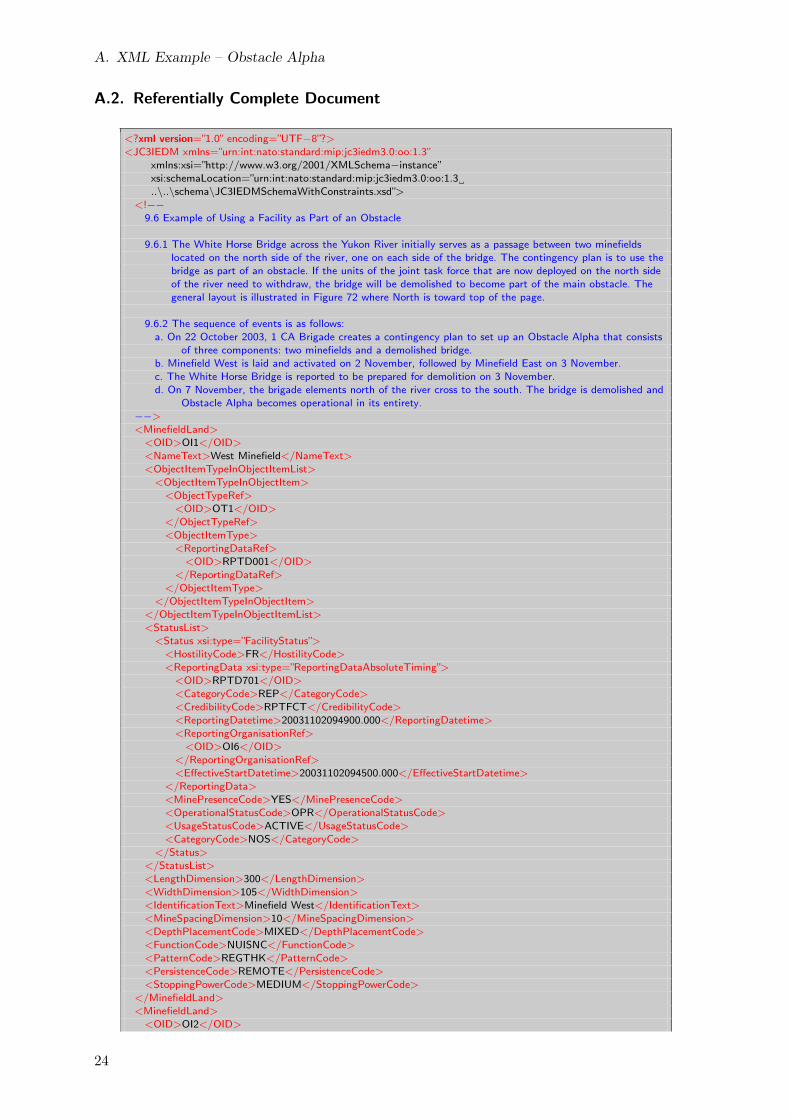
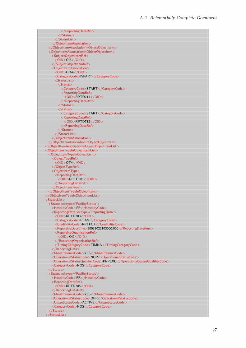
In this appendix, the complete instance XML documents are presented for the vignette describedin section 4 on page 14. The formal specification of the operational scenario by means of theJC3IEDM is shown in section A.1. The XML document in section A.2 describes the completehistory of the operational scenario. The documents in section A.3 illustrate replication-basedinformation exchange with incremental updates.
22

A.1. JC3IEDM Model
A.1. JC3IEDM Model
OID = OI1
West Minefield : MinefieldLand
OID = OI2
East Minefield : MinefieldLand
OID = OI4
Obstacle Alpha : MilitaryObstacle
OID = OI3
White Horse Bridge : Bridge
: FacilityStatus
: FacilityStatus
: FacilityStatus
: FacilityStatus
OID = OIA1
: ObjectItemAssociation
OID = OIA2
: ObjectItemAssociation
OID = OIA4
: ObjectItemAssociation
: ObjectItemAssociationStatus
: ObjectItemAssociationStatus
: ObjectItemAssociationStatus
: ObjectItemAssociationStatus
: ObjectItemAssociationStatus
: ObjectItemAssociationStatus
OID = 701
: ReportingDataAbsoluteTiming
OID = RPTD001
: ReportingData
OID = RPTD704
: ReportingData
OID = 702
: ReportingDataAbsoluteTiming
OID = RPTD705
: ReportingDataAbsoluteTiming
OID = 712
: ReportingDataAbsoluteTiming
OID = 711
: ReportingData
: ObjectItemType
OID = OT1
LandMineField : ObjectType
OID = OI6
1 CA Bde : Unit
: ObjectItemType
: ObjectItemType
OID = OT6
CA Brigade : UnitType
OID = RPTD005
: ReportingDataAbsoluteTiming
OID = OI5
Intelligence : Unit
: ObjectItemType
OID = OT5
Intelligence : UnitType
: ObjectItemType
OID = OT3
IronHorse : BridgeTyoe
: FacilityStatus
OID = OT4
CompoundObstacle : MilitaryObstacleType
: ObjectItemType
: FacilityStatus
OID = RPTD703
: ReportingData
23
A. XML Example – Obstacle Alpha
A.2. Referentially Complete Document
<?xml version=”1.0” encoding=”UTF−8”?><JC3IEDM xmlns=”urn:int:nato:standard:mip:jc3iedm3.0:oo:1.3”
xmlns:xsi=”http://www.w3.org/2001/XMLSchema−instance”xsi:schemaLocation=”urn:int:nato:standard:mip:jc3iedm3.0:oo:1.3..\..\schema\JC3IEDMSchemaWithConstraints.xsd”>
<!−−9.6 Example of Using a Facility as Part of an Obstacle
9.6.1 The White Horse Bridge across the Yukon River initially serves as a passage between two minefieldslocated on the north side of the river, one on each side of the bridge. The contingency plan is to use thebridge as part of an obstacle. If the units of the joint task force that are now deployed on the north sideof the river need to withdraw, the bridge will be demolished to become part of the main obstacle. Thegeneral layout is illustrated in Figure 72 where North is toward top of the page.
9.6.2 The sequence of events is as follows:a. On 22 October 2003, 1 CA Brigade creates a contingency plan to set up an Obstacle Alpha that consists
of three components: two minefields and a demolished bridge.b. Minefield West is laid and activated on 2 November, followed by Minefield East on 3 November.c. The White Horse Bridge is reported to be prepared for demolition on 3 November.d. On 7 November, the brigade elements north of the river cross to the south. The bridge is demolished and
Obstacle Alpha becomes operational in its entirety.−−><MinefieldLand>
<OID>OI1</OID><NameText>West Minefield</NameText><ObjectItemTypeInObjectItemList>
<ObjectItemTypeInObjectItem><ObjectTypeRef>
<OID>OT1</OID></ObjectTypeRef><ObjectItemType>
<ReportingDataRef><OID>RPTD001</OID>
</ReportingDataRef></ObjectItemType>
</ObjectItemTypeInObjectItem></ObjectItemTypeInObjectItemList><StatusList>
<Status xsi:type=”FacilityStatus”><HostilityCode>FR</HostilityCode><ReportingData xsi:type=”ReportingDataAbsoluteTiming”>
<OID>RPTD701</OID><CategoryCode>REP</CategoryCode><CredibilityCode>RPTFCT</CredibilityCode><ReportingDatetime>20031102094900.000</ReportingDatetime><ReportingOrganisationRef>
<OID>OI6</OID></ReportingOrganisationRef><EffectiveStartDatetime>20031102094500.000</EffectiveStartDatetime>
</ReportingData><MinePresenceCode>YES</MinePresenceCode><OperationalStatusCode>OPR</OperationalStatusCode><UsageStatusCode>ACTIVE</UsageStatusCode><CategoryCode>NOS</CategoryCode>
</Status></StatusList><LengthDimension>300</LengthDimension><WidthDimension>105</WidthDimension><IdentificationText>Minefield West</IdentificationText><MineSpacingDimension>10</MineSpacingDimension><DepthPlacementCode>MIXED</DepthPlacementCode><FunctionCode>NUISNC</FunctionCode><PatternCode>REGTHK</PatternCode><PersistenceCode>REMOTE</PersistenceCode><StoppingPowerCode>MEDIUM</StoppingPowerCode>
</MinefieldLand><MinefieldLand>
<OID>OI2</OID>
24

A.2. Referentially Complete Document
<NameText>East Minefield</NameText><ObjectItemTypeInObjectItemList>
<ObjectItemTypeInObjectItem><ObjectTypeRef>
<OID>OT1</OID></ObjectTypeRef><ObjectItemType>
<ReportingDataRef><OID>RPTD001</OID>
</ReportingDataRef></ObjectItemType>
</ObjectItemTypeInObjectItem></ObjectItemTypeInObjectItemList><StatusList>
<Status xsi:type=”FacilityStatus”><HostilityCode>FR</HostilityCode><ReportingData xsi:type=”ReportingDataAbsoluteTiming”>
<OID>RPTD702</OID><CategoryCode>REP</CategoryCode><CredibilityCode>RPTFCT</CredibilityCode><ReportingDatetime>20031103154200.000</ReportingDatetime><ReportingOrganisationRef>
<OID>OI6</OID></ReportingOrganisationRef><EffectiveStartDatetime>20031103153000.000</EffectiveStartDatetime>
</ReportingData><MinePresenceCode>YES</MinePresenceCode><OperationalStatusCode>OPR</OperationalStatusCode><UsageStatusCode>ACTIVE</UsageStatusCode><CategoryCode>NOS</CategoryCode>
</Status></StatusList><LengthDimension>320</LengthDimension><WidthDimension>90</WidthDimension><IdentificationText>Minefield East</IdentificationText><MineSpacingDimension>10</MineSpacingDimension><DepthPlacementCode>MIXED</DepthPlacementCode><FunctionCode>NUISNC</FunctionCode><PatternCode>REGTHK</PatternCode><PersistenceCode>REMOTE</PersistenceCode><StoppingPowerCode>MEDIUM</StoppingPowerCode>
</MinefieldLand><Bridge>
<OID>OI3</OID><NameText>White Horse Bridge</NameText><!−− the following tag provides additional information on typing −−><ObjectItemTypeInObjectItemList>
<ObjectItemTypeInObjectItem><ObjectTypeRef>
<OID>OT3</OID></ObjectTypeRef><ObjectItemType>
<ReportingDataRef><OID>RPTD001</OID>
</ReportingDataRef></ObjectItemType>
</ObjectItemTypeInObjectItem></ObjectItemTypeInObjectItemList><StatusList>
<Status xsi:type=”FacilityStatus”><HostilityCode>FR</HostilityCode><ReportingData xsi:type=”ReportingData”>
<OID>RPTD704</OID><CategoryCode>REP</CategoryCode><CredibilityCode>RPTFCT</CredibilityCode><ReportingDatetime>20031103171000.000</ReportingDatetime><ReportingOrganisationRef>
<OID>OI6</OID></ReportingOrganisationRef><TimingCategoryCode>TIMNA</TimingCategoryCode>
25

A. XML Example – Obstacle Alpha
</ReportingData><DemolitionStatusCode>PRPEXE</DemolitionStatusCode><MinePresenceCode>NO</MinePresenceCode><OperationalStatusCode>OPR</OperationalStatusCode><OperationalStatusQualifierCode>PASABL</OperationalStatusQualifierCode><CategoryCode>NOS</CategoryCode>
</Status><Status xsi:type=”FacilityStatus”>
<HostilityCode>FR</HostilityCode><ReportingDataRef>
<OID>RPTD705</OID></ReportingDataRef><DemolitionStatusCode>EXECTD</DemolitionStatusCode><MinePresenceCode>NO</MinePresenceCode><OperationalStatusCode>NOP</OperationalStatusCode><OperationalStatusQualifierCode>DSTRYD</OperationalStatusQualifierCode><CategoryCode>NOS</CategoryCode>
</Status></StatusList><LengthDimension>200</LengthDimension><WidthDimension>10</WidthDimension><LongestSpanLengthDimension>40</LongestSpanLengthDimension><SpanCount>5</SpanCount><UsageCode>RLWYVH</UsageCode>
</Bridge><MilitaryObstacle>
<OID>OI4</OID><NameText>Obstacle Alpha</NameText><ObjectItemAssociationInObjectObjectItemList>
<ObjectItemAssociationInObjectObjectItem><SubjectObjectItemRef>
<OID>OI1</OID></SubjectObjectItemRef><ObjectItemAssociation>
<OID>OIA1</OID><CategoryCode>ISPART</CategoryCode><StatusList>
<Status><CategoryCode>START</CategoryCode><ReportingDataRef>
<OID>RPTD711</OID></ReportingDataRef>
</Status><Status>
<CategoryCode>START</CategoryCode><ReportingDataRef>
<OID>RPTD712</OID></ReportingDataRef>
</Status></StatusList>
</ObjectItemAssociation></ObjectItemAssociationInObjectObjectItem><ObjectItemAssociationInObjectObjectItem>
<SubjectObjectItemRef><OID>OI2</OID>
</SubjectObjectItemRef><ObjectItemAssociation>
<OID>OIA2</OID><CategoryCode>ISPART</CategoryCode><StatusList>
<Status><CategoryCode>START</CategoryCode><ReportingDataRef>
<OID>RPTD711</OID></ReportingDataRef>
</Status><Status>
<CategoryCode>START</CategoryCode><ReportingDataRef>
<OID>RPTD712</OID>
26
A.2. Referentially Complete Document
</ReportingDataRef></Status>
</StatusList></ObjectItemAssociation>
</ObjectItemAssociationInObjectObjectItem><ObjectItemAssociationInObjectObjectItem>
<SubjectObjectItemRef><OID>OI3</OID>
</SubjectObjectItemRef><ObjectItemAssociation>
<OID>OIA4</OID><CategoryCode>ISPART</CategoryCode><StatusList>
<Status><CategoryCode>START</CategoryCode><ReportingDataRef>
<OID>RPTD711</OID></ReportingDataRef>
</Status><Status>
<CategoryCode>START</CategoryCode><ReportingDataRef>
<OID>RPTD712</OID></ReportingDataRef>
</Status></StatusList>
</ObjectItemAssociation></ObjectItemAssociationInObjectObjectItem>
</ObjectItemAssociationInObjectObjectItemList><ObjectItemTypeInObjectItemList>
<ObjectItemTypeInObjectItem><ObjectTypeRef>
<OID>OT4</OID></ObjectTypeRef><ObjectItemType>
<ReportingDataRef><OID>RPTD001</OID>
</ReportingDataRef></ObjectItemType>
</ObjectItemTypeInObjectItem></ObjectItemTypeInObjectItemList><StatusList>
<Status xsi:type=”FacilityStatus”><HostilityCode>FR</HostilityCode><ReportingData xsi:type=”ReportingData”>
<OID>RPTD703</OID><CategoryCode>PLAN</CategoryCode><CredibilityCode>RPTFCT</CredibilityCode><ReportingDatetime>20031022103000.000</ReportingDatetime><ReportingOrganisationRef>
<OID>OI6</OID></ReportingOrganisationRef><TimingCategoryCode>TIMNA</TimingCategoryCode>
</ReportingData><MinePresenceCode>YES</MinePresenceCode><OperationalStatusCode>NOP</OperationalStatusCode><OperationalStatusQualifierCode>PRPEXE</OperationalStatusQualifierCode><CategoryCode>NOS</CategoryCode>
</Status><Status xsi:type=”FacilityStatus”>
<HostilityCode>FR</HostilityCode><ReportingDataRef>
<OID>RPTD705</OID></ReportingDataRef><MinePresenceCode>YES</MinePresenceCode><OperationalStatusCode>OPR</OperationalStatusCode><UsageStatusCode>ACTIVE</UsageStatusCode><CategoryCode>NOS</CategoryCode>
</Status></StatusList>
27

A. XML Example – Obstacle Alpha
<LengthDimension>650</LengthDimension><WidthDimension>325</WidthDimension><CategoryCode>NOS</CategoryCode>
</MilitaryObstacle><ReportingDataAbsoluteTiming>
<OID>RPTD705</OID><CategoryCode>REP</CategoryCode><CredibilityCode>RPTFCT</CredibilityCode><ReportingDatetime>20031107081000.000</ReportingDatetime><ReportingOrganisationRef>
<OID>OI6</OID></ReportingOrganisationRef><EffectiveStartDatetime>20031107080000.000</EffectiveStartDatetime>
</ReportingDataAbsoluteTiming><ReportingData>
<OID>RPTD711</OID><CategoryCode>PLAN</CategoryCode><CredibilityCode>RPTFCT</CredibilityCode><ReportingDatetime>20031022103000.000</ReportingDatetime><ReportingOrganisationRef>
<OID>OI6</OID></ReportingOrganisationRef><TimingCategoryCode>TIMNA</TimingCategoryCode>
</ReportingData><ReportingDataAbsoluteTiming>
<OID>RPTD712</OID><CategoryCode>REP</CategoryCode><CredibilityCode>RPTFCT</CredibilityCode><ReportingDatetime>20031107081000.000</ReportingDatetime><ReportingOrganisationRef>
<OID>OI6</OID></ReportingOrganisationRef><EffectiveStartDatetime>20031107080000.000</EffectiveStartDatetime>
</ReportingDataAbsoluteTiming><!−−
the following content provides reference information required to complete the example−−>
<MilitaryObstacleType><!−− MilitaryObstacleType of the minefields −−><OID>OT1</OID><DummyIndicatorCode>NO</DummyIndicatorCode><NameText>LandMinefield</NameText><CategoryCode>MINEFD</CategoryCode>
</MilitaryObstacleType><BridgeType>
<!−− BridgeType for White Horse Bridge −−><OID>OT3</OID><DummyIndicatorCode>NO</DummyIndicatorCode><NameText>Iron Horse</NameText><DesignTypeCode>CNTLVR</DesignTypeCode>
</BridgeType><MilitaryObstacleType>
<!−− MilitaryObstacleType of Obstacle Alpha −−><OID>OT4</OID><DummyIndicatorCode>NO</DummyIndicatorCode><NameText>Compound obstacle</NameText><CategoryCode>NOS</CategoryCode>
</MilitaryObstacleType><ReportingData>
<!−− ReportingData for associating Obstacle Alpha and its components with their types −−><OID>RPTD001</OID><CategoryCode>REP</CategoryCode><CredibilityCode>RPTFCT</CredibilityCode><ReportingDatetime>20031022103000.000</ReportingDatetime><ReportingOrganisationRef>
<OID>OI6</OID></ReportingOrganisationRef><TimingCategoryCode>TIMNA</TimingCategoryCode>
</ReportingData><Unit>
28

A.2. Referentially Complete Document
<!−− Unit that is reporting its activities −−><OID>OI6</OID><NameText>1 CA Bde</NameText><ObjectItemTypeInObjectItemList>
<ObjectItemTypeInObjectItem><ObjectType xsi:type=”UnitType”>
<OID>OT6</OID><DummyIndicatorCode>NO</DummyIndicatorCode><NameText>CA Brigade</NameText><CommandFunctionIndicatorCode>YES</CommandFunctionIndicatorCode><ServiceCode>ARMY</ServiceCode><CategoryCode>COMBAT</CategoryCode><ArmCategoryCode>INF</ArmCategoryCode><SizeCode>BDE</SizeCode>
</ObjectType><ObjectItemType>
<ReportingDataRef><OID>RPTD005</OID>
</ReportingDataRef></ObjectItemType>
</ObjectItemTypeInObjectItem></ObjectItemTypeInObjectItemList><FormalAbbreviatedNameText>1 CA Bde</FormalAbbreviatedNameText>
</Unit><Unit>
<!−− Unit that first recorded the White Horse Bridge −−><OID>OI5</OID><NameText>Intelligence</NameText><ObjectItemTypeInObjectItemList>
<ObjectItemTypeInObjectItem><ObjectType xsi:type=”UnitType”>
<OID>OT5</OID><DummyIndicatorCode>NO</DummyIndicatorCode><NameText>Intelligence</NameText><CommandFunctionIndicatorCode>NO</CommandFunctionIndicatorCode><ServiceCode>JOINT</ServiceCode><!−− check category code −−><CategoryCode>COMSPT</CategoryCode><ArmCategoryCode>MILINT</ArmCategoryCode><SizeCode>BDE</SizeCode>
</ObjectType><ObjectItemType>
<ReportingDataRef><OID>RPTD005</OID>
</ReportingDataRef></ObjectItemType>
</ObjectItemTypeInObjectItem></ObjectItemTypeInObjectItemList><FormalAbbreviatedNameText>Intel</FormalAbbreviatedNameText>
</Unit><ReportingDataAbsoluteTiming>
<!−− ReportingData for associating 1 CA Brigade and the Intelligence unit with their types −−><OID>RPTD005</OID><CategoryCode>REP</CategoryCode><ReportingDatetime>20020102000000.000</ReportingDatetime><ReportingOrganisationRef>
<OID>OI5</OID></ReportingOrganisationRef><EffectiveStartDatetime>20020102000000.000</EffectiveStartDatetime>
</ReportingDataAbsoluteTiming></JC3IEDM>
29

A. XML Example – Obstacle Alpha
A.3. Incremental Information Exchange
A.3.1. Initial Type Information Exchange on 02 January 2002
<?xml version=”1.0” encoding=”UTF−8”?><JC3IEDM xmlns=”urn:int:nato:standard:mip:jc3iedm3.0:oo:1.3”
xmlns:xsi=”http://www.w3.org/2001/XMLSchema−instance”xsi:schemaLocation=”urn:int:nato:standard:mip:jc3iedm3.0:oo:1.3 ..\..\schema\JC3IEDMSchema.xsd”>
<!−−9.6 Example of Using a Facility as Part of an Obstacle
9.6.1 ...
9.6.2 The sequence of events is as follows:a. On 22 October 2003, 1 CA Brigade creates a contingency plan to set up an Obstacle Alpha that consists
of three components: two minefields and a demolished bridge.b. Minefield West is laid and activated on 2 November, followed by Minefield East on 3 November.c. The White Horse Bridge is reported to be prepared for demolition on 3 November.d. On 7 November, the brigade elements north of the river cross to the south. The bridge is demolished and
Obstacle Alpha becomes operational in its entirety.−−><!−− Initial information exchange on 02 January 2002 −−><MilitaryObstacleType>
<!−− MilitaryObstacleType of the minefields −−><OID>OT1</OID><DummyIndicatorCode>NO</DummyIndicatorCode><NameText>LandMinefield</NameText><CategoryCode>MINEFD</CategoryCode>
</MilitaryObstacleType><BridgeType>
<!−− BridgeType for White Horse Bridge −−><OID>OT3</OID><DummyIndicatorCode>NO</DummyIndicatorCode><NameText>Iron Horse</NameText><DesignTypeCode>CNTLVR</DesignTypeCode>
</BridgeType><MilitaryObstacleType>
<!−− MilitaryObstacleType of Obstacle Alpha −−><OID>OT4</OID><DummyIndicatorCode>NO</DummyIndicatorCode><NameText>Compound obstacle</NameText><CategoryCode>NOS</CategoryCode>
</MilitaryObstacleType><Unit>
<!−− Unit that is reporting its activities −−><OID>OI6</OID><NameText>1 CA Bde</NameText><ObjectItemTypeInObjectItemList>
<ObjectItemTypeInObjectItem><ObjectType xsi:type=”UnitType”>
<OID>OT6</OID><DummyIndicatorCode>NO</DummyIndicatorCode><NameText>CA Brigade</NameText><CommandFunctionIndicatorCode>YES</CommandFunctionIndicatorCode><ServiceCode>ARMY</ServiceCode><CategoryCode>COMBAT</CategoryCode><ArmCategoryCode>INF</ArmCategoryCode><SizeCode>BDE</SizeCode>
</ObjectType><ObjectItemType>
<ReportingDataRef><OID>RPTD005</OID>
</ReportingDataRef></ObjectItemType>
</ObjectItemTypeInObjectItem></ObjectItemTypeInObjectItemList><FormalAbbreviatedNameText>1 CA Bde</FormalAbbreviatedNameText>
</Unit><Unit>
<!−− Unit that first recorded the White Horse Bridge −−>
30
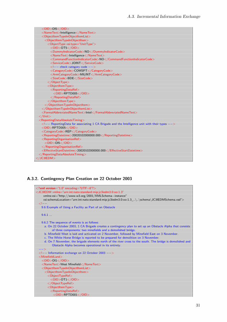
A.3. Incremental Information Exchange
<OID>OI5</OID><NameText>Intelligence</NameText><ObjectItemTypeInObjectItemList>
<ObjectItemTypeInObjectItem><ObjectType xsi:type=”UnitType”>
<OID>OT5</OID><DummyIndicatorCode>NO</DummyIndicatorCode><NameText>Intelligence</NameText><CommandFunctionIndicatorCode>NO</CommandFunctionIndicatorCode><ServiceCode>JOINT</ServiceCode><!−− check category code −−><CategoryCode>COMSPT</CategoryCode><ArmCategoryCode>MILINT</ArmCategoryCode><SizeCode>BDE</SizeCode>
</ObjectType><ObjectItemType>
<ReportingDataRef><OID>RPTD005</OID>
</ReportingDataRef></ObjectItemType>
</ObjectItemTypeInObjectItem></ObjectItemTypeInObjectItemList><FormalAbbreviatedNameText>Intel</FormalAbbreviatedNameText>
</Unit><ReportingDataAbsoluteTiming>
<!−− ReportingData for associating 1 CA Brigade and the Intelligence unit with their types −−><OID>RPTD005</OID><CategoryCode>REP</CategoryCode><ReportingDatetime>20020102000000.000</ReportingDatetime><ReportingOrganisationRef>
<OID>OI5</OID></ReportingOrganisationRef><EffectiveStartDatetime>20020102000000.000</EffectiveStartDatetime>
</ReportingDataAbsoluteTiming></JC3IEDM>
A.3.2. Contingency Plan Creation on 22 October 2003
<?xml version=”1.0” encoding=”UTF−8”?><JC3IEDM xmlns=”urn:int:nato:standard:mip:jc3iedm3.0:oo:1.3”
xmlns:xsi=”http://www.w3.org/2001/XMLSchema−instance”xsi:schemaLocation=”urn:int:nato:standard:mip:jc3iedm3.0:oo:1.3 ..\..\schema\JC3IEDMSchema.xsd”>
<!−−9.6 Example of Using a Facility as Part of an Obstacle
9.6.1 ...
9.6.2 The sequence of events is as follows:a. On 22 October 2003, 1 CA Brigade creates a contingency plan to set up an Obstacle Alpha that consists
of three components: two minefields and a demolished bridge.b. Minefield West is laid and activated on 2 November, followed by Minefield East on 3 November.c. The White Horse Bridge is reported to be prepared for demolition on 3 November.d. On 7 November, the brigade elements north of the river cross to the south. The bridge is demolished and
Obstacle Alpha becomes operational in its entirety.−−><!−− Information exchange on 22 October 2003 −−><MinefieldLand>
<OID>OI1</OID><NameText>West Minefield</NameText><ObjectItemTypeInObjectItemList>
<ObjectItemTypeInObjectItem><ObjectTypeRef>
<OID>OT1</OID></ObjectTypeRef><ObjectItemType>
<ReportingDataRef><OID>RPTD001</OID>
31

A. XML Example – Obstacle Alpha
</ReportingDataRef></ObjectItemType>
</ObjectItemTypeInObjectItem></ObjectItemTypeInObjectItemList><LengthDimension>300</LengthDimension><WidthDimension>105</WidthDimension><IdentificationText>Minefield West</IdentificationText><MineSpacingDimension>10</MineSpacingDimension><DepthPlacementCode>MIXED</DepthPlacementCode><FunctionCode>NUISNC</FunctionCode><PatternCode>REGTHK</PatternCode><PersistenceCode>REMOTE</PersistenceCode><StoppingPowerCode>MEDIUM</StoppingPowerCode>
</MinefieldLand><MinefieldLand>
<OID>OI2</OID><NameText>East Minefield</NameText><ObjectItemTypeInObjectItemList>
<ObjectItemTypeInObjectItem><ObjectTypeRef>
<OID>OT1</OID></ObjectTypeRef><ObjectItemType>
<ReportingDataRef><OID>RPTD001</OID>
</ReportingDataRef></ObjectItemType>
</ObjectItemTypeInObjectItem></ObjectItemTypeInObjectItemList><LengthDimension>320</LengthDimension><WidthDimension>90</WidthDimension><IdentificationText>Minefield East</IdentificationText><MineSpacingDimension>10</MineSpacingDimension><DepthPlacementCode>MIXED</DepthPlacementCode><FunctionCode>NUISNC</FunctionCode><PatternCode>REGTHK</PatternCode><PersistenceCode>REMOTE</PersistenceCode><StoppingPowerCode>MEDIUM</StoppingPowerCode>
</MinefieldLand><Bridge>
<OID>OI3</OID><NameText>White Horse Bridge</NameText><!−− the following tag provides additional information on typing −−><ObjectItemTypeInObjectItemList>
<ObjectItemTypeInObjectItem><ObjectTypeRef>
<OID>OT3</OID></ObjectTypeRef><ObjectItemType>
<ReportingDataRef><OID>RPTD001</OID>
</ReportingDataRef></ObjectItemType>
</ObjectItemTypeInObjectItem></ObjectItemTypeInObjectItemList><LengthDimension>200</LengthDimension><WidthDimension>10</WidthDimension><LongestSpanLengthDimension>40</LongestSpanLengthDimension><SpanCount>5</SpanCount><UsageCode>RLWYVH</UsageCode>
</Bridge><MilitaryObstacle>
<OID>OI4</OID><NameText>Obstacle Alpha</NameText><ObjectItemAssociationInObjectObjectItemList>
<ObjectItemAssociationInObjectObjectItem><SubjectObjectItemRef>
<OID>OI1</OID></SubjectObjectItemRef><ObjectItemAssociation>
32
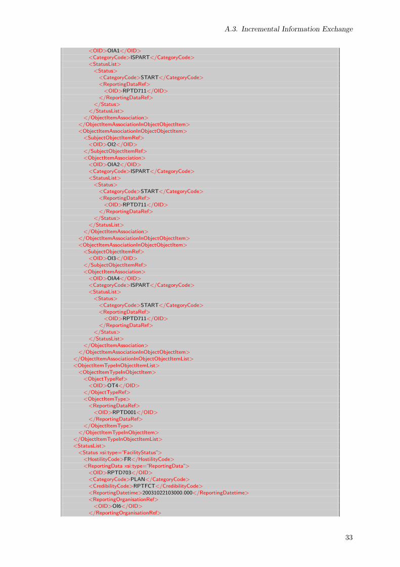
A.3. Incremental Information Exchange
<OID>OIA1</OID><CategoryCode>ISPART</CategoryCode><StatusList>
<Status><CategoryCode>START</CategoryCode><ReportingDataRef>
<OID>RPTD711</OID></ReportingDataRef>
</Status></StatusList>
</ObjectItemAssociation></ObjectItemAssociationInObjectObjectItem><ObjectItemAssociationInObjectObjectItem>
<SubjectObjectItemRef><OID>OI2</OID>
</SubjectObjectItemRef><ObjectItemAssociation>
<OID>OIA2</OID><CategoryCode>ISPART</CategoryCode><StatusList>
<Status><CategoryCode>START</CategoryCode><ReportingDataRef>
<OID>RPTD711</OID></ReportingDataRef>
</Status></StatusList>
</ObjectItemAssociation></ObjectItemAssociationInObjectObjectItem><ObjectItemAssociationInObjectObjectItem>
<SubjectObjectItemRef><OID>OI3</OID>
</SubjectObjectItemRef><ObjectItemAssociation>
<OID>OIA4</OID><CategoryCode>ISPART</CategoryCode><StatusList>
<Status><CategoryCode>START</CategoryCode><ReportingDataRef>
<OID>RPTD711</OID></ReportingDataRef>
</Status></StatusList>
</ObjectItemAssociation></ObjectItemAssociationInObjectObjectItem>
</ObjectItemAssociationInObjectObjectItemList><ObjectItemTypeInObjectItemList>
<ObjectItemTypeInObjectItem><ObjectTypeRef>
<OID>OT4</OID></ObjectTypeRef><ObjectItemType>
<ReportingDataRef><OID>RPTD001</OID>
</ReportingDataRef></ObjectItemType>
</ObjectItemTypeInObjectItem></ObjectItemTypeInObjectItemList><StatusList>
<Status xsi:type=”FacilityStatus”><HostilityCode>FR</HostilityCode><ReportingData xsi:type=”ReportingData”>
<OID>RPTD703</OID><CategoryCode>PLAN</CategoryCode><CredibilityCode>RPTFCT</CredibilityCode><ReportingDatetime>20031022103000.000</ReportingDatetime><ReportingOrganisationRef>
<OID>OI6</OID></ReportingOrganisationRef>
33

A. XML Example – Obstacle Alpha
<TimingCategoryCode>TIMNA</TimingCategoryCode></ReportingData><MinePresenceCode>YES</MinePresenceCode><OperationalStatusCode>NOP</OperationalStatusCode><OperationalStatusQualifierCode>PRPEXE</OperationalStatusQualifierCode><CategoryCode>NOS</CategoryCode>
</Status></StatusList><LengthDimension>650</LengthDimension><WidthDimension>325</WidthDimension><CategoryCode>NOS</CategoryCode>
</MilitaryObstacle><ReportingData>
<OID>RPTD711</OID><CategoryCode>PLAN</CategoryCode><CredibilityCode>RPTFCT</CredibilityCode><ReportingDatetime>20031022103000.000</ReportingDatetime><ReportingOrganisationRef>
<OID>OI6</OID></ReportingOrganisationRef><TimingCategoryCode>TIMNA</TimingCategoryCode>
</ReportingData><!−−
the following content provides reference information required to complete the example−−>
<ReportingData><!−− ReportingData for associating Obstacle Alpha and its components with their types −−><OID>RPTD001</OID><CategoryCode>REP</CategoryCode><CredibilityCode>RPTFCT</CredibilityCode><ReportingDatetime>20031022103000.000</ReportingDatetime><ReportingOrganisationRef>
<OID>OI6</OID></ReportingOrganisationRef><TimingCategoryCode>TIMNA</TimingCategoryCode>
</ReportingData></JC3IEDM>
A.3.3. Activation of Minefield West on 02 November 2003
<?xml version=”1.0” encoding=”UTF−8”?><JC3IEDM xmlns=”urn:int:nato:standard:mip:jc3iedm3.0:oo:1.3”
xmlns:xsi=”http://www.w3.org/2001/XMLSchema−instance”xsi:schemaLocation=”urn:int:nato:standard:mip:jc3iedm3.0:oo:1.3 ..\..\schema\JC3IEDMSchema.xsd”>
<!−−9.6 Example of Using a Facility as Part of an Obstacle
9.6.1 ...
9.6.2 The sequence of events is as follows:a. On 22 October 2003, 1 CA Brigade creates a contingency plan to set up an Obstacle Alpha that consists
of three components: two minefields and a demolished bridge.b. Minefield West is laid and activated on 2 November, followed by Minefield East on 3 November.c. The White Horse Bridge is reported to be prepared for demolition on 3 November.d. On 7 November, the brigade elements north of the river cross to the south. The bridge is demolished and
Obstacle Alpha becomes operational in its entirety.−−><!−− Information exchange on 2 November 2003 −−><MinefieldLandRef>
<OID>OI1</OID><StatusList>
<Status xsi:type=”FacilityStatus”><HostilityCode>FR</HostilityCode><ReportingData xsi:type=”ReportingDataAbsoluteTiming”>
<OID>RPTD701</OID><CategoryCode>REP</CategoryCode><CredibilityCode>RPTFCT</CredibilityCode>
34

A.3. Incremental Information Exchange
<ReportingDatetime>20031102094900.000</ReportingDatetime><ReportingOrganisationRef>
<OID>OI6</OID></ReportingOrganisationRef><EffectiveStartDatetime>20031102094500.000</EffectiveStartDatetime>
</ReportingData><MinePresenceCode>YES</MinePresenceCode><OperationalStatusCode>OPR</OperationalStatusCode><UsageStatusCode>ACTIVE</UsageStatusCode><CategoryCode>NOS</CategoryCode>
</Status></StatusList>
</MinefieldLandRef></JC3IEDM>
A.3.4. Activation of Minefield East on 03 November 2003 15:42
<?xml version=”1.0” encoding=”UTF−8”?><JC3IEDM xmlns=”urn:int:nato:standard:mip:jc3iedm3.0:oo:1.3”
xmlns:xsi=”http://www.w3.org/2001/XMLSchema−instance”xsi:schemaLocation=”urn:int:nato:standard:mip:jc3iedm3.0:oo:1.3 ..\..\schema\JC3IEDMSchema.xsd”>
<!−−9.6 Example of Using a Facility as Part of an Obstacle
9.6.1 ...
9.6.2 The sequence of events is as follows:a. On 22 October 2003, 1 CA Brigade creates a contingency plan to set up an Obstacle Alpha that consists
of three components: two minefields and a demolished bridge.b. Minefield West is laid and activated on 2 November, followed by Minefield East on 3 November.c. The White Horse Bridge is reported to be prepared for demolition on 3 November.d. On 7 November, the brigade elements north of the river cross to the south. The bridge is demolished and
Obstacle Alpha becomes operational in its entirety.−−><!−− Information exchange on 3 November 2003 15:42 −−><MinefieldLandRef>
<OID>OI2</OID><StatusList>
<Status xsi:type=”FacilityStatus”><HostilityCode>FR</HostilityCode><ReportingData xsi:type=”ReportingDataAbsoluteTiming”>
<OID>RPTD702</OID><CategoryCode>REP</CategoryCode><CredibilityCode>RPTFCT</CredibilityCode><ReportingDatetime>20031103154200.000</ReportingDatetime><ReportingOrganisationRef>
<OID>OI6</OID></ReportingOrganisationRef><EffectiveStartDatetime>20031103153000.000</EffectiveStartDatetime>
</ReportingData><MinePresenceCode>YES</MinePresenceCode><OperationalStatusCode>OPR</OperationalStatusCode><UsageStatusCode>ACTIVE</UsageStatusCode><CategoryCode>NOS</CategoryCode>
</Status></StatusList>
</MinefieldLandRef></JC3IEDM>
35
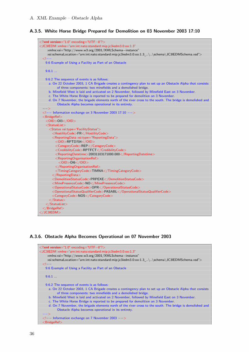
A. XML Example – Obstacle Alpha
A.3.5. White Horse Bridge Prepared for Demolition on 03 November 2003 17:10
<?xml version=”1.0” encoding=”UTF−8”?><JC3IEDM xmlns=”urn:int:nato:standard:mip:jc3iedm3.0:oo:1.3”
xmlns:xsi=”http://www.w3.org/2001/XMLSchema−instance”xsi:schemaLocation=”urn:int:nato:standard:mip:jc3iedm3.0:oo:1.3 ..\..\schema\JC3IEDMSchema.xsd”>
<!−−9.6 Example of Using a Facility as Part of an Obstacle
9.6.1 ...
9.6.2 The sequence of events is as follows:a. On 22 October 2003, 1 CA Brigade creates a contingency plan to set up an Obstacle Alpha that consists
of three components: two minefields and a demolished bridge.b. Minefield West is laid and activated on 2 November, followed by Minefield East on 3 November.c. The White Horse Bridge is reported to be prepared for demolition on 3 November.d. On 7 November, the brigade elements north of the river cross to the south. The bridge is demolished and
Obstacle Alpha becomes operational in its entirety.−−><!−− Information exchange on 3 November 2003 17:10 −−><BridgeRef>
<OID>OI3</OID><StatusList>
<Status xsi:type=”FacilityStatus”><HostilityCode>FR</HostilityCode><ReportingData xsi:type=”ReportingData”>
<OID>RPTD704</OID><CategoryCode>REP</CategoryCode><CredibilityCode>RPTFCT</CredibilityCode><ReportingDatetime>20031103171000.000</ReportingDatetime><ReportingOrganisationRef>
<OID>OI6</OID></ReportingOrganisationRef><TimingCategoryCode>TIMNA</TimingCategoryCode>
</ReportingData><DemolitionStatusCode>PRPEXE</DemolitionStatusCode><MinePresenceCode>NO</MinePresenceCode><OperationalStatusCode>OPR</OperationalStatusCode><OperationalStatusQualifierCode>PASABL</OperationalStatusQualifierCode><CategoryCode>NOS</CategoryCode>
</Status></StatusList>
</BridgeRef></JC3IEDM>
A.3.6. Obstacle Alpha Becomes Operational on 07 November 2003
<?xml version=”1.0” encoding=”UTF−8”?><JC3IEDM xmlns=”urn:int:nato:standard:mip:jc3iedm3.0:oo:1.3”
xmlns:xsi=”http://www.w3.org/2001/XMLSchema−instance”xsi:schemaLocation=”urn:int:nato:standard:mip:jc3iedm3.0:oo:1.3 ..\..\schema\JC3IEDMSchema.xsd”>
<!−−9.6 Example of Using a Facility as Part of an Obstacle
9.6.1 ...
9.6.2 The sequence of events is as follows:a. On 22 October 2003, 1 CA Brigade creates a contingency plan to set up an Obstacle Alpha that consists
of three components: two minefields and a demolished bridge.b. Minefield West is laid and activated on 2 November, followed by Minefield East on 3 November.c. The White Horse Bridge is reported to be prepared for demolition on 3 November.d. On 7 November, the brigade elements north of the river cross to the south. The bridge is demolished and
Obstacle Alpha becomes operational in its entirety.−−><!−− Information exchange on 7 November 2003 −−><BridgeRef>
36

A.3. Incremental Information Exchange
<OID>OI3</OID><StatusList>
<Status xsi:type=”FacilityStatus”><HostilityCode>FR</HostilityCode><ReportingDataRef>
<OID>RPTD705</OID></ReportingDataRef><DemolitionStatusCode>EXECTD</DemolitionStatusCode><MinePresenceCode>NO</MinePresenceCode><OperationalStatusCode>NOP</OperationalStatusCode><OperationalStatusQualifierCode>DSTRYD</OperationalStatusQualifierCode><CategoryCode>NOS</CategoryCode>
</Status></StatusList>
</BridgeRef><MilitaryObstacleRef>
<OID>OI4</OID><ObjectItemAssociationInObjectObjectItemList>
<ObjectItemAssociationInObjectObjectItem><SubjectObjectItemRef>
<OID>OI1</OID></SubjectObjectItemRef><ObjectItemAssociationRef>
<OID>OIA1</OID><StatusList>
<Status><CategoryCode>START</CategoryCode><ReportingDataRef>
<OID>RPTD712</OID></ReportingDataRef>
</Status></StatusList>
</ObjectItemAssociationRef></ObjectItemAssociationInObjectObjectItem><ObjectItemAssociationInObjectObjectItem>
<SubjectObjectItemRef><OID>OI2</OID>
</SubjectObjectItemRef><ObjectItemAssociationRef>
<OID>OIA2</OID><StatusList>
<Status><CategoryCode>START</CategoryCode><ReportingDataRef>
<OID>RPTD712</OID></ReportingDataRef>
</Status></StatusList>
</ObjectItemAssociationRef></ObjectItemAssociationInObjectObjectItem><ObjectItemAssociationInObjectObjectItem>
<SubjectObjectItemRef><OID>OI3</OID>
</SubjectObjectItemRef><ObjectItemAssociationRef>
<OID>OIA4</OID><StatusList>
<Status><CategoryCode>START</CategoryCode><ReportingDataRef>
<OID>RPTD712</OID></ReportingDataRef>
</Status></StatusList>
</ObjectItemAssociationRef></ObjectItemAssociationInObjectObjectItem>
</ObjectItemAssociationInObjectObjectItemList><StatusList>
<Status xsi:type=”FacilityStatus”><HostilityCode>FR</HostilityCode>
37
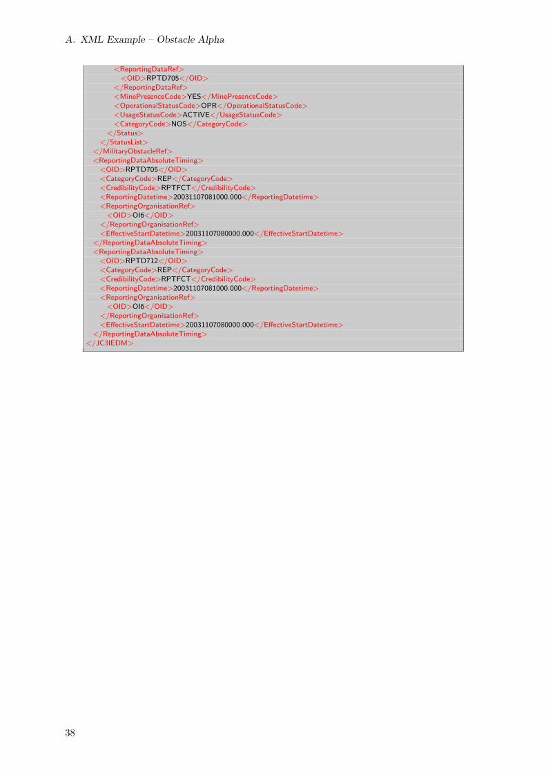
A. XML Example – Obstacle Alpha
<ReportingDataRef><OID>RPTD705</OID>
</ReportingDataRef><MinePresenceCode>YES</MinePresenceCode><OperationalStatusCode>OPR</OperationalStatusCode><UsageStatusCode>ACTIVE</UsageStatusCode><CategoryCode>NOS</CategoryCode>
</Status></StatusList>
</MilitaryObstacleRef><ReportingDataAbsoluteTiming>
<OID>RPTD705</OID><CategoryCode>REP</CategoryCode><CredibilityCode>RPTFCT</CredibilityCode><ReportingDatetime>20031107081000.000</ReportingDatetime><ReportingOrganisationRef>
<OID>OI6</OID></ReportingOrganisationRef><EffectiveStartDatetime>20031107080000.000</EffectiveStartDatetime>
</ReportingDataAbsoluteTiming><ReportingDataAbsoluteTiming>
<OID>RPTD712</OID><CategoryCode>REP</CategoryCode><CredibilityCode>RPTFCT</CredibilityCode><ReportingDatetime>20031107081000.000</ReportingDatetime><ReportingOrganisationRef>
<OID>OI6</OID></ReportingOrganisationRef><EffectiveStartDatetime>20031107080000.000</EffectiveStartDatetime>
</ReportingDataAbsoluteTiming></JC3IEDM>
38