an msc.nastran primer for rotordynamics · an msc.nastran primer for rotordynamics chuck lawrence...
TRANSCRIPT
An MSC.Nastran Primer for Rotordynamics
Chuck LawrenceNASA Glenn
Cleveland, Ohio

MSC.Nastran Rotordynamics Damage Resulting from Blade-Out
MSC.Nastran Rotordynamics Types of Analyses
Engine performance• critical speeds• whirl • forced response (unbalance, cabin noise) • damping• Static Analysis (external loads, maneuver loads)
Transient blade off• structural system response• windmilling

MSC.Nastran Rotordynamics Typical Structural ModelEngine Static Structure

MSC.Nastran Rotordynamics Background
• 1998 Meeting with engine and airframe manufacturers and MSC.Software
• All manufacturers performing similar typesof analysis
• All manufacturers using similar, but self developed and maintained, software tools
• Common need to develop standardized analysis tools
MSC.Nastran Rotordynamics Participants
• Boeing Commercial Airplane Group• Pratt & Whitney • General Electric Aircraft Engines • Rolls Royce • Ohio Aerospace Institute • MSC.Software• NASA
• Form Working Group• Define General Program Plan, Benefits and
Advocacy Package• Secure Funding• Develop “Boeing” Document• Bring MSC.Software Aboard• Develop Software Requirements Document• Develop Software• Validate Software• Phase II
MSC.Nastran Rotordynamics Process

MSC.Nastran Rotordynamics Unique Features
• General Finite ElementCapabilities
• Component Substructuring• Condensation of 3D Rotors• Rotor Damping• Non-Constant Rotor Speed• Complex Mass Unbalance• Fan-Case Interactions• Multi-Spool Rotors• Maneuver Loads• Parametric Excitations

Primer Table on ContentsI. Single Spool Rotor
1. Geometry2. Gravity Loads3. Maneuver Loads4. Transient Unbalance Response5. Synchronous Vibration (Critical Speeds)6. Asynchronous Vibration (Whirl Analysis)7. Comparison of Damping Models
II. Dual Spool Rotor1. Geometry 2. Synchronous Vibration (Critical Speeds) 3. Asynchronous Vibration (Whirl Analysis)4. Transient Unbalance Response
III. Squeeze Film DamperIV. Three Dimensional Model Reduction

Single Spool Rotor With Rotor and Support Damping
XZ
YSupportSprings
Rigid ShaftDisk
Unbalance Load
101 102 103
(104) (105)
SupportDamper
RotationVector
RotorDamper

1 $2 $ ROTOR DYNAMICS SAMPLE PROBLEM3 $ SINGLE ROTOR, UNBALANCE LOAD4 $5 6 ID SAMPLE ROTOR7 SOL 1298 DIAG 5, 8, 569 CEND
10
12 TSTEP= 10013 SET 500 = 10214 DISPLACEMENT(PUNCH) = 50015 16 BEGIN BULK17
20 TSTEPNL, 100, 40000, 1.E-3, 2021 22 $23 $ ROTOR 124 $
30 31 GRID, 101, , 0., 0., 0.32 GRID, 102, , 1., 0., 0., , 1433 GRID, 103, , 2., 0., 0.34 GRID, 104, , 0., 0., 0.35 GRID, 105, , 2., 0., 0.36 37 RBE2, 1001, 102, 123456, 101, 10338 RBE2, 1002, 101, 123456, 10439 RBE2, 1003, 103, 123456, 10540 41 CONM2, 1004, 102, , 50.,42 , 5.0, , 15.0, , , 15.043 44 CELAS1, 1005, 1000, 104, 245 CELAS1, 1006, 1000, 104, 346 CELAS1, 1007, 1000, 105, 247 CELAS1, 1008, 1000, 105, 348 PELAS, 1000, 1.0E+5, 0.049 50 ENDDATA
Single Spool Rotor Transient Analysis
11 RGYRO= 111
18 UNBALNC, 111, 100.0, 102, 0., 1., 0.,19 , 1.0, 0.0, 0.0, 0.0, , NONE
26 ROTORG 10 101 THRU 10327 RSPINT, 10, 101, 102, , RPM, 10028 TABLED1, 10029 , 0.0, 800., 100.0, 800., ENDT
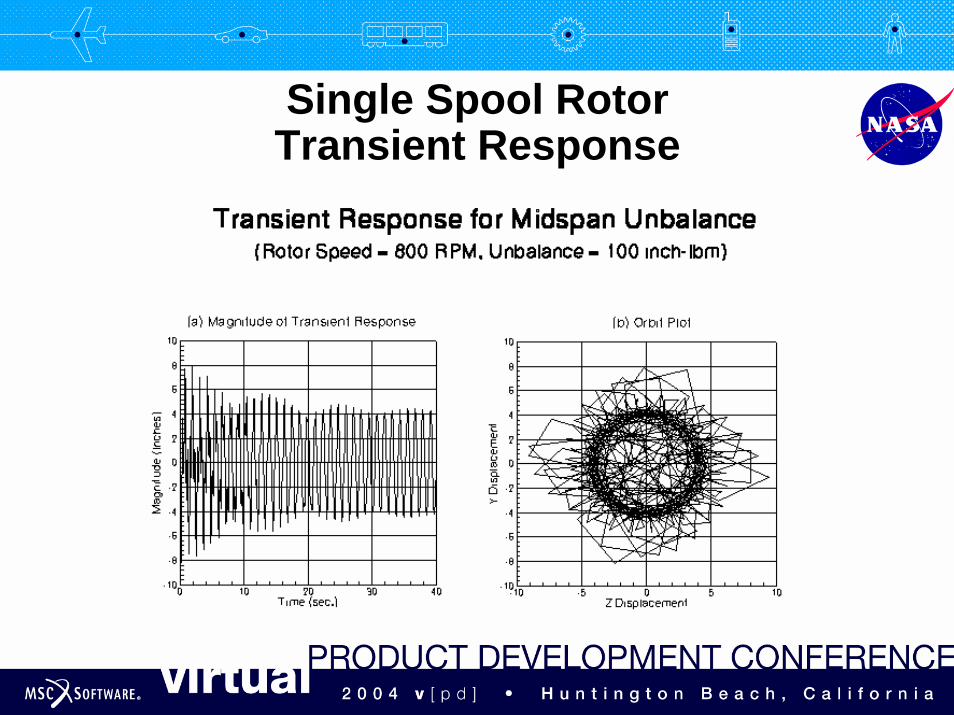
Single Spool RotorTransient Response
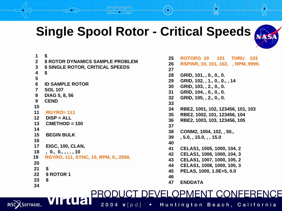
Single Spool Rotor - Critical Speeds
1 $2 $ ROTOR DYNAMICS SAMPLE PROBLEM3 $ SINGLE ROTOR, CRITICAL SPEEDS4 $5 6 ID SAMPLE ROTOR7 SOL 1078 DIAG 5, 8, 569 CEND
10
12 DISP = ALL13 CMETHOD = 10014 15 BEGIN BULK16 17 EIGC, 100, CLAN,18 , 0., 0., , , , , 10
20 21 $22 $ ROTOR 123 $24
11 RGYRO= 111
19 RGYRO, 111, SYNC, 10, RPM, 0., 2500.
27 28 GRID, 101, , 0., 0., 0.29 GRID, 102, , 1., 0., 0., , 1430 GRID, 103, , 2., 0., 0.31 GRID, 104, , 0., 0., 0.32 GRID, 105, , 2., 0., 0.33 34 RBE2, 1001, 102, 123456, 101, 10335 RBE2, 1002, 101, 123456, 10436 RBE2, 1003, 103, 123456, 10537 38 CONM2, 1004, 102, , 50.,39 , 5.0, , 15.0, , , 15.040 41 CELAS1, 1005, 1000, 104, 242 CELAS1, 1006, 1000, 104, 343 CELAS1, 1007, 1000, 105, 244 CELAS1, 1008, 1000, 105, 345 PELAS, 1000, 1.0E+5, 0.046 47 ENDDATA
25 ROTORG 10 101 THRU 10326 RSPINR, 10, 101, 102, , RPM, 9999.

Single Spool RotorCampbell Diagram and Critical Speeds
Mode 1,2
Mode 3
Mode 4
1/rev2/rev
First Critical
Second Critical
Third Critical


Dual Spool Rotor Asynchronous Vibration
1 $2 $ ROTOR DYNAMICS SAMPLE PROBLEM3 $ Dual Spool Rotor, Asynchronous Vibration4 $5 6 ID SAMPLE ROTOR7 SOL 1078 DIAG 5, 8, 56 9 CEND
10
12 DISP = ALL13 CMETHOD = 10014 15 BEGIN BULK16
18 19 EIGC,100,CLAN,20 , 0., 0., , , , , 1421 22 $23 $ ROTOR 124 $25
29 ...52 $53 $ ROTOR 254 $55
59 ...81 ENDDATA
11 RGYRO = 300
17 RGYRO, 300, ASYNC, 20, FREQ, 0., 100. , 40.
26 ROTORG 10 101 THRU 10427 RSPINR, 10, 101, 102, , FREQ, 20., 25., 35.,28 , 50.
56 ROTORG 20 201 THRU 20357 RSPINR, 20, 201, 202, , FREQ, 10., 20., 30.,58 , 40.

Dual Spool RotorRelative Rotor Speeds

Dual Spool RotorCampbell Diagram and Critical Speeds
Mode 1,2
Mode 3,4
Mode 5
1/rev
1st & 2nd Critical
3rd & 4th Critical
5th Critical
Mode 6
6th Critical
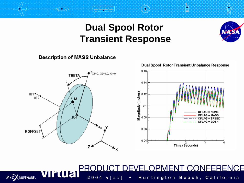
Dual Spool Rotor Transient Response
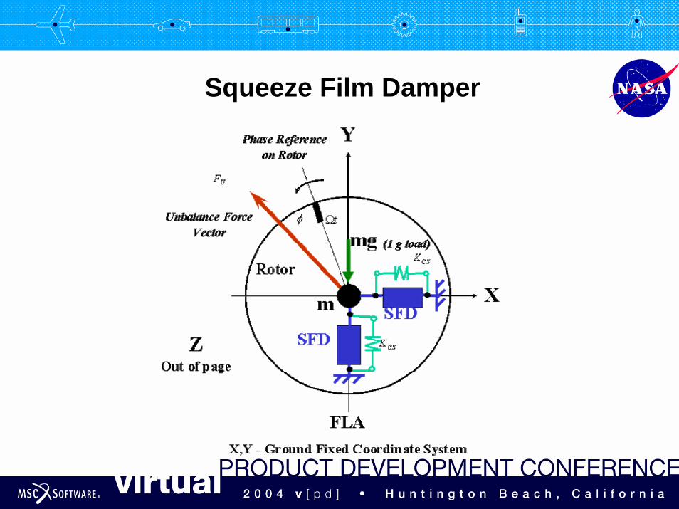
Squeeze Film Damper
MSC.Nastran RotordynamicsSummary
• Unified front and team effort enabled rotordynamics to be implemented into MSC.Nastran
• Rotordynamics primer is available for distribution
• MSC.Software did an outstanding job of satisfying customer’s needs