an investigation into the base sliding response of rigid concrete gravity dams to dynamic loading
TRANSCRIPT
EARTHQUAKE ENGINEERING AND STRUCTURAL DYNAMICS, VOL. 25 ,19 98 (1996)
AN INVESTIGATION INTO THE BASE SLIDING RESPONSE OF RIGID CONCRETE GRAVITY DAMS TO DYNAMIC LOADING
R. A. MIR* AND C. A. TAYLORt Deparfrnent of Civil Engineering, Earthquake Engineering Research Centre, University of Bristol, Queens Building, University Walk, Bristol
BS8 1 TR, U. K .
SUMMARY
A series of dynamic slip tests on a concrete gravity dam model was conducted on a shaking table. The aim of the experiments was to investigate the dynamically induced sliding and overturning characteristics of a typical low height gravity dam monolith cracked at its base. Tests indicated that downstream sliding is the main instability that could be expected during an earthquake. Dynamic, finite element analyses of the experimental model, using a Lagrangian contact surface algorithm, were also performed. A comparison of the experimental and analytical responses indicated that the seismically induced slip can be predicted reasonably by such a contact surface algorithm implemented in a standard finite element package. A comparison of observed displacements with Newmark's sliding block displacements indicated that a conservative estimate of seismic induced slip of a gravity dam could be obtained by using Newmark's sliding block concept, generally adopted for earth dams and embankments.
KEY WORDS: gravity dams; models; shaking table; sliding
1. INTRODUCTION
It is well recognized that the pseudo-static loads determined on the basis of a seismic coefficient are very small when compared to the actual forces expected in a gravity dam during a strong earthquake.' Therefore, it is highly unlikely that the traditional safety for sliding and overturning stabilities can be satisfied if the pseudo-static lateral forces were to represent the true dynamic forces acting on a dam during a moderate to intense earthquake. However, the evaluation of seismic sliding and overturning safety on the basis of static loads has little meaning in the context of the oscillatory nature of earthquake loading and the corresponding dam response. Therefore, the normal criteria for evaluating static stability may not be appropriate to evaluate the seismic stability of concrete gravity dams. During an earthquake, as the forces acting on the dam change constantly with time, it is desirable to assess the stability criteria at various time instants during the entire duration of the earthquake. Of particular importance is the evaluation of the critical earthquake accelerations at which the sliding or overturning of a dam could be expected.
Evaluation of seismic stability of concrete gravity dams has not received much attention in the past. Among the few analytical investigations carried out, notable are the works by Leger and Katsouli4 and Chopra and Zhang.' Leger and Katsouli developed an analytical procedure to determine the dynamic sliding and rocking response of typical gravity dam monoliths. The proposed method of analysis recognized the oscillatory nature of earthquake loads and permitted the monitoring of sliding and uplifting response of a dam monolith under earthquake loading. Chopra and Zhang explored the earthquake-induced sliding of a gravity dam monolith supported on a plane surface without bond. Separate analytical procedures were presented for rigid and flexible dams. Sliding analyses of a typical gravity dam monolith under the El Centro,
*Postgraduate student 'Reader
CCC 0098-8847/96/010079-20 0 1996 by John Wiley & Sons, Ltd
Received I2 October 1994 Revised 14 August 1995

80 R. A. MIR A N D C. A. TAYLOR
1940 and Taft, 1952 earthquakes predicted a progressive pattern of sliding displacement in the downstream direction.
The present paper describes the results of a shaking table study performed to explore the dynamically induced sliding and overturning characteristics of a gravity dam model. The experimental findings are also compared to the sliding response predicted by a non-linear, large displacement analysis performed using a typical contact surface algorithm that was implemented in a standard finite element computer program, SOLVIA.6-8 The principal objectives of this study were:
(1) To investigate if the sliding and possible overturning under dynamic loads are associated with critical
(2) To explore if the commonly used sliding-block theories for embankment dams9-' could be applied to
( 3 ) To validate a simple analytical procedure for the evaluation of the sliding response of rigid bodies
accelerations of the input.
evaluate the seismic induced sliding of concrete gravity dams.
under earthquake motions.
2. ASSUMPTIONS
Keeping in view the exploratory nature of the tests, various simplifying assumptions were made to obtain data which could be interpreted with confidence. It was assumed that:
1. The dam was perfectly rigid. 2. The dam-foundation interface was horizontal. 3. There was no mutual bond between the dam and the foundation and the motion was resisted by pure
4. Hydrodynamic force was absent. 5. Uplift pressures were absent. 6. The dam was subjected to horizontal accelerations only. 7. The dynamic response of the dam, including rigid body rotational inertia, was ignored. 8. A 2-D plane stress idealisation was valid.
friction at the interface.
3. CRITICAL ACCELERATIONS FOR SLIDING AND OVERTURNING
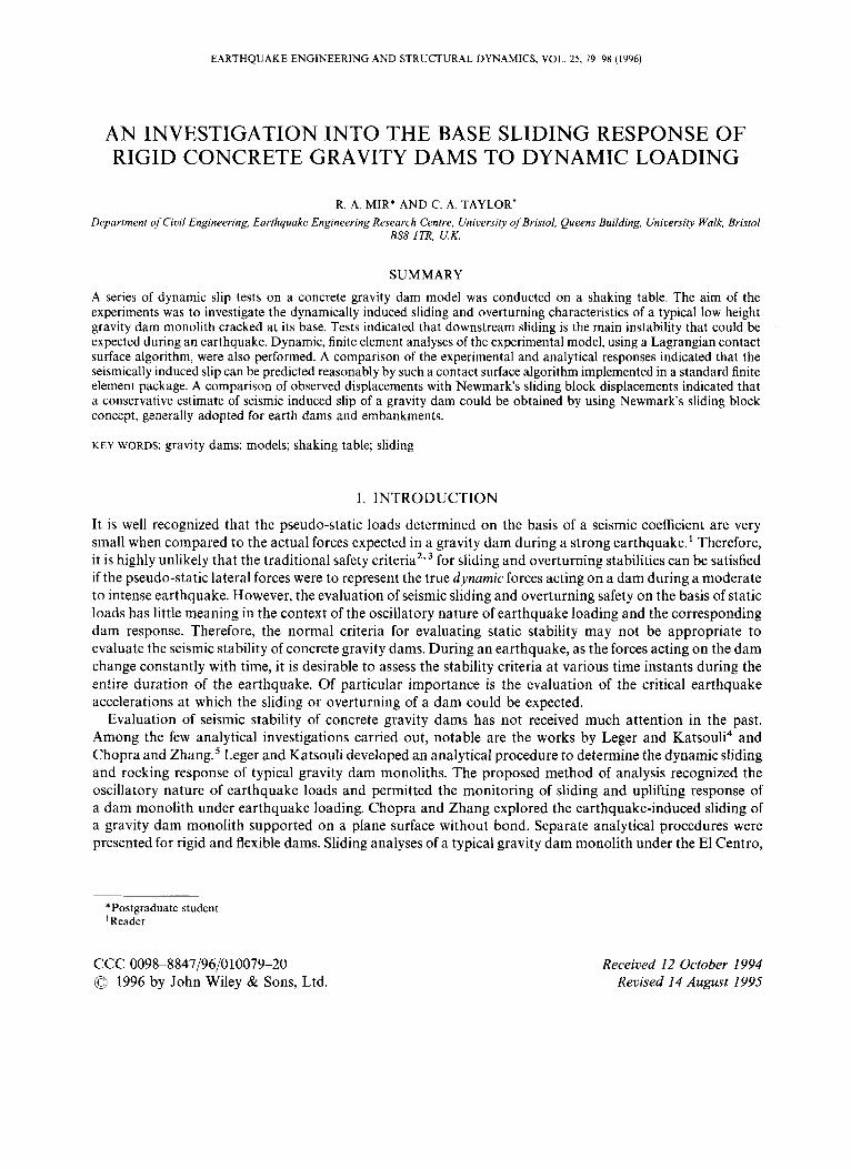
With the above listed assumptions, the forces acting on a gravity dam section supported on a base that moves with an acceleration a(t), prior to sliding or overturning, are as shown in Figure 1. At any instant of time the dam is in equilibrium under a set of four forces:
(a) The weight of the dam, Mg, acting vertically downwards. (b) The hydrostatic force, F h , acting horizontally in or against the direction of motion. (c) The frictional force, Ff = (pMg) , acting in the direction of motion. (d) The inertia force, Ma(t), acting opposite to the direction of motion.
For the downstream sliding equilibrium of Figure l(a), it can be shown that
Similarly for the upstream sliding equilibrium of Figure l(b):
BASE SLIDING RESPONSE 81
a) b)
Figure 1. Forces acting on a gravity dam section (a) downstream sliding (b) upstream sliding
where Sac)d.s is the critical acceleration just about to cause sliding in the downstream direction, is the critical acceleration to cause sliding in the upstream direction, p is the coefficient of friction at the dam-support interface, M is the mass of the dam section and Fh is the total hydrostatic force acting on the dam.
I t is evident that the critical acceleration needed to cause upstream sliding is greater than the critical acceleration to cause downstream sliding. However, if the hydrostatic pressure is absent, the critical acceleration for upstream and downstream sliding is the same and is given by
sac)u.s = Sac)d.s = pg (3)
Considering the dam section to be rigid, there is a possibility of the dam rotating about its toe or heel, thus, raising a possibility of downstream or upstream overturning, respectively. From the overturning equilibrium of Figures l(a) and l(b), respectively, it can be shown that
and
where oac)d.s is the critical acceleration to initiate downstream overturning of the dam section, ouc)u.s is the critical acceleration to initiate upstream overturning of the dam section, B is the base length of the dam section, H is the height of water on the upstream side of the dam, b is the horizontal distance of the centre of gravity of the dam section from the heel and h is the vertical distance of the centre of gravity of the dam section from the heel.
From equations (4) and (5) it is clear that expressions for upstream and downstream critical overturning accelerations are independent of interface friction.
For a typical triangular dam section with reservoir empty, equations (4) and (5) can be approximately written as

82 R. A. MIR A N D C. A. TAYLOR
Hence, for a dry reservoir condition the critical acceleration to initiate upstream overturning about the heel is approximately half the value of that required to initiate downstream overturning about the toe.
It must be noted that the above expressions for critical accelerations are derived for the ideal cases of pure translational or rotational movement of the rigid dam. However, it is possible that a rigid body might undergo a motion consisting of a combination of sliding and rotation when subjected to an earthquake excitation. The possibility of more complex motions, such as, translational and rotational jumps has also been investigated in the past." If such motions occur, the above expressions for critical accelerations may not be valid.
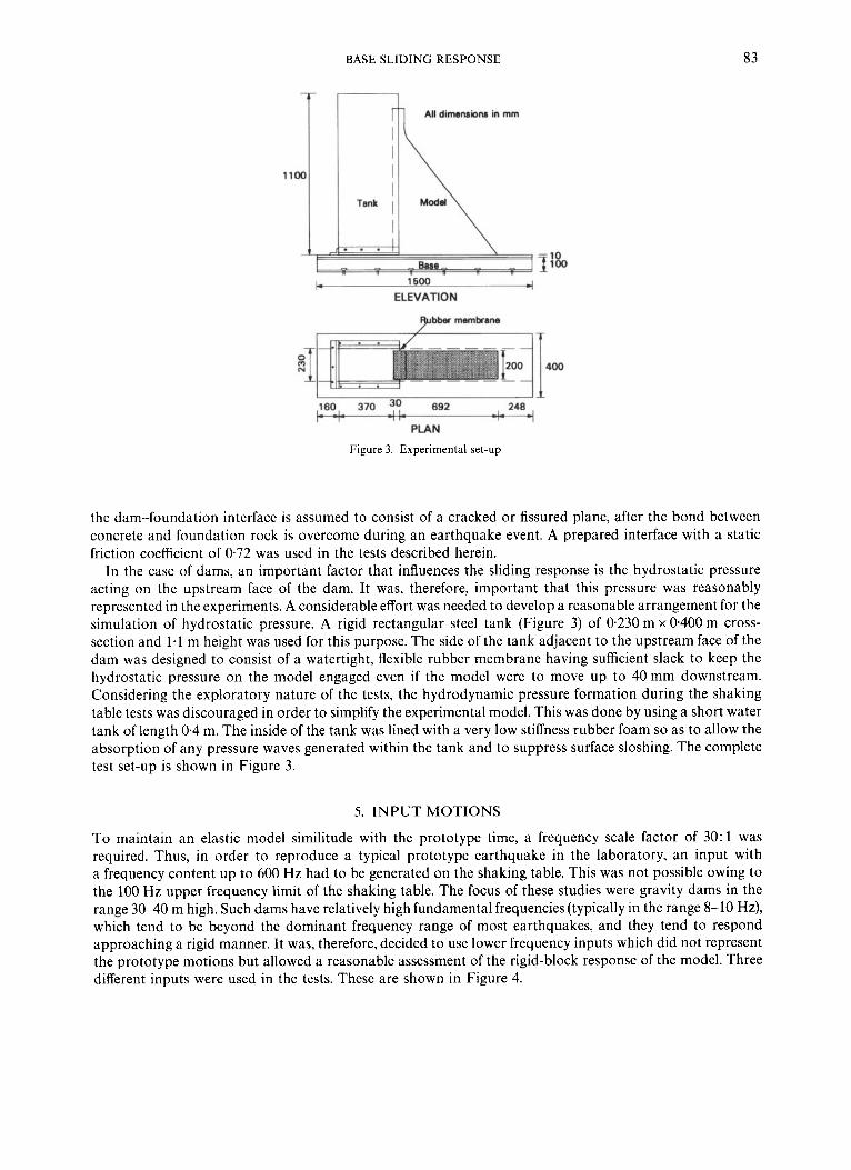
4. EXPERIMENTAL SET-UP
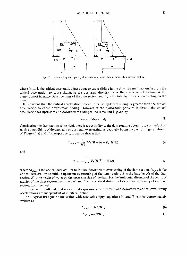
As explained above, several assumptions in experimental modelling were made in order to obtain simple estimates of the dynamically induced slippage and to investigate the possibility of overturning of the dam monoliths. This resulted in an idealized experimental model which did not represent a full similitude with the prototype. The sectional details of the model monolith used for testing are shown in Figure 2. The overall geometry of the test specimen represented a 1 : 30 scaled version of a 30 m high dam monolith with upstream and downstream slopes of 2 and 70 per cent, respectively. This geometry is typical of a moderately high U.K. dam which has been the centre of several linear and non-linear investigations for the evaluation of seismic r e s p o n ~ e . ' ~ . ' ~ The model was made of prototype concrete as the strength was not a controlling parameter. Therefore, the model similitude with the prototype length, density and modulus of elasticity was maintained. In this sense, the model would represent a true elastic similitude with the prototype if a frequency scale factor of 30: 1 (inverse of the length scale) were adopted in the dynamic testing.
In practice, the dam monolith is bonded to the surface of a rock which is usually inclined upwards from upstream to downstream. However, in the experiments carried out here, the dam base was assumed to be horizontal and resting on a plane and rigid surface without any mutual bond. Thus, the motion of the dam relative to base could be assumed to be resisted only by the friction at the interface. This scenario is possible if
80 c_
960 q 900
600
0.0
692
All dimensions in mm
Figure 2. Sectional details of the dam model
BASE SLIDING RESPONSE 83
T - 3 All dimemiom in mm
ELEVATION
Nbber membrane
16O1 370 90 692 I -
PLAN
Figure 3. Experimental set-up
the dam-foundation interface is assumed to consist of a cracked or fissured plane, after the bond between concrete and foundation rock is overcome during an earthquake event. A prepared interface with a static friction coefficient of 0.72 was used in the tests described herein.
In the case of dams, an important factor that influences the sliding response is the hydrostatic pressure acting on the upstream face of the dam. It was, therefore, important that this pressure was reasonably represented in the experiments. A considerable effort was needed to develop a reasonable arrangement for the simulation of hydrostatic pressure. A rigid rectangular steel tank (Figure 3) of 0.230 m x 0400 m cross- section and 1.1 m height was used for this purpose. The side of the tank adjacent to the upstream face of the dam was designed to consist of a watertight, flexible rubber membrane having sufficient slack to keep the hydrostatic pressure on the model engaged even if the model were to move up to 40mm downstream. Considering the exploratory nature of the tests, the hydrodynamic pressure formation during the shaking table tests was discouraged in order to simplify the experimental model. This was done by using a short water tank of length 0.4 m. The inside of the tank was lined with a very low stiffness rubber foam so as to allow the absorption of any pressure waves generated within the tank and to suppress surface sloshing. The complete test set-up is shown in Figure 3.
5. INPUT MOTIONS
To maintain an elastic model similitude with the prototype time, a frequency scale factor of 30:l was required. Thus, in order to reproduce a typical prototype earthquake in the laboratory, an input with a frequency content up to 600 Hz had to be generated on the shaking table. This was not possible owing to the 100 Hz upper frequency limit of the shaking table. The focus of these studies were gravity dams in the range 3 W O m high. Such dams have relatively high fundamental frequencies (typically in the range 8-10 Hz), which tend to be beyond the dominant frequency range of most earthquakes, and they tend to respond approaching a rigid manner. It was, therefore, decided to use lower frequency inputs which did not represent the prototype motions but allowed a reasonable assessment of the rigid-block response of the model. Three different inputs were used in the tests. These are shown in Figure 4.

84 R. A. MIR AND C. A. TAYLOR
a) Sine pulse input 1 2 I
I
0 1 c
-1 2 ' 0 0 0 2 04 0 6
Time (sec)
b) Sine dwell input
-1 2 1 2 0 3 0 4 0 5 0 I 0 1 0 I
I Time (sec)
c) Eurocode 6 compatlbk Input
0 1 - 0 4
P 3 3 00 - c L e - 8 4 4 P
-0 1
, t I . .-
0.0 1.0 2.0 3.0 4.0 5.0 6.0 7.0 8 0 9.0 t o o I l .0 1 2 0
Time (sec)
Figure 4. Input motions used during shaking table tests
The first type of input, shown in Figure 4(a), was a simple sine pulse of frequency 7.5 Hz. It was difficult to match the pulse exactly to the table motion as some free vibration response could not be separated from the table motion at a pulse amplitude higher than about 0-3 g. It is believed that the actual sliding displacement' under an earthquake takes place in steps under the influence of peak acceleration pulses. Therefore, it was considered worthwhile to give a well-defined single acceleration pulse as input and assess the sliding and overturning characteristics of the monolith.
BASE SLIDING RESPONSE 85
Eurocode 8 spectrum for 5% damping
2.5 m . r 2
f 1.5 .- c
- $ 1 2 0.5
-+---'I 0 1 2 3 4 5 6 7
Period I s
Figure 5. Eurocode 8 response spectrum normalised to 1.Og zero period acceleration
The second type of input used was a sine dwell motion as shown in Figure 4(b). This was a sine function of 5 Hz frequency having an initial rising ramp for 5 cycles followed by a 10 cycle constant amplitude motion and finally a decaying ramp for another 5 cycles of motion.
The third type of input, shown in Figure 4(c), was a simulated earthquake of 12 s duration. This earthquake was compatible to the Eur0code-8~~ response spectrum for 5 per cent damping, shown normalized to a zero period acceleration of 1.0 g in Figure 5.
6. INSTRUMENTATION
The response sensing instruments used during the shaking table tests consisted of displacement transducers and accelerometers. Two Indikon, non-contacting displacement transducers, one each in the horizontal and vertical directions, were positioned just near the toe of the model in order to measure directly the sliding and uplifting response at this location. For the tests without hydrostatic pressure, two similar transducers were mounted near the heel of the model. A Setra 141 accelerometer was mounted near the base of the model, on the downstream face, so as to monitor any change in the base acceleration due to sudden slippage of the model. Another Setra 141 accelerometer was mounted in the stream direction at the crest of the model in order to monitor the development of any dynamic response over the height of the model. An accelerometer at the crest was also mounted in the lateral direction so as to check the occurrence of out-of-plane vibrations. All transducers were calibrated using the Quality Assurance Procedures of the Bristol EERC."
7. DISCUSSION OF TEST RESULTS
A total of six tests was conducted on the Engineering and Physical Sciences Research Council shaking table'* at Bristol University. The tests were conducted under three different input motions (described earlier) with and without the hydrostatic pressure on the upstream face of the model. This paper concentrates on the results of three tests which included the hydrostatic pressure. Each test, under a selected input, was conducted in steps, gradually increasing the input magnitude from lower to higher levels, until the occurrence of a sudden slip. Typically, the tests were conducted in peak amplitude increments of 0.1 g so as to locate the critical failure acceleration as closely as possible.
7.1. Sliding response The measured coefficient of static friction at the dam-foundation interface was 0.72. The mass of the dam
model was 186 kg and the height of the water in the tests was 0.95 m. Therefore, from equations (1) and (2) the critical accelerations for downstream and upstream sliding of the model should be 0.235 and 1.20g,

86 R. A. MIR A N D C. A. TAYLOR
-0.5 0.8 0.9 1 1.1 1.2 1.3 1.4
Time (Sec)
(--+ Acceleraticdg (D/S +ve) - Displacement (D/S +ve) - - Critical acceleration 1 Figure 6 . Sliding response under sine pulse input
respectively. Similarly from equations (4) and (5), critical accelerations to initiate downstream and upstream overturning should be approximately 0.97 and 1.21 g, respectively.
Figure 6 shows the sine pulse input under which sliding of the dam monolith occurred. The corresponding sliding response is shown in the same figure. It is clear from the figure that sliding of the model in the downstream direction started when the input acceleration in the upstream direction was just about critical (0.235 g). A total slip of 1.34 mm occurred within 0.05 s as the magnitude of the acceleration pulse reached 0.42 g. Because of the presence of hydrostatic pressures, downstream sliding of the model occurred at an acceleration level much lower than that at which upstream overturning or sliding would be expected. Therefore, the failure response consisted of pure sliding with little evidence of overturning or upstream sliding, as is clear from Figure 6.
Figure 7 shows the sine dwell input and the corresponding sliding response of the dam monolith. As in the case of the single pulse input, sliding occurred only in the downstream direction because of a very high resistance to sliding in the upstream direction due to the presence of water. It is clear from Figure 7(a) that each of the constant magnitude downstream sine pulses caused some sliding displacement that remained almost unchanged during the reverse pulse of the same magnitude. Sliding occurred under all the sine pulses having peak acceleration greater than the critical value of 0.235 g. A total sliding displacement of 6.9 mm occurred in ten steps during the ten constant amplitude cycles of the dwell motion. However, the magnitude of sliding displacements in the successive cycles was not constant which was partly due to the fact that the dwell motion reproduced by the shaking table did not have exactly identical upstream pulses during the constant amplitude duration.
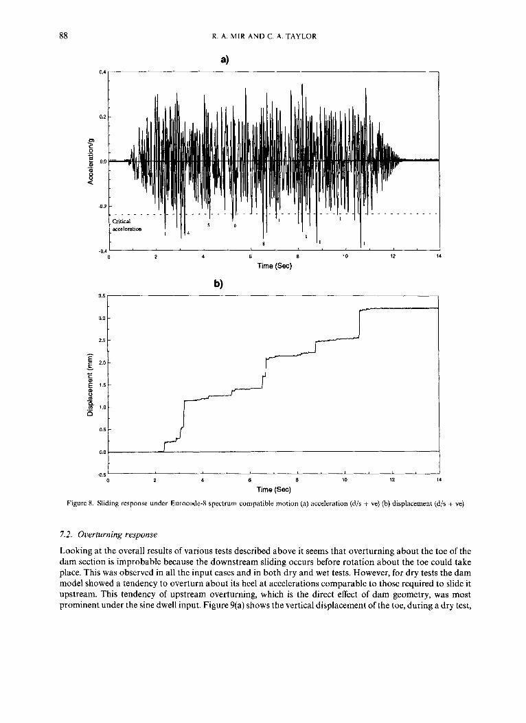
The Eurocode-8 response spectrum compatible motion that caused sliding during the wet test is shown in Figure 8 along with the corresponding sliding response time history. The dotted line in Figure 8(a) represents the critical acceleration for downstream sliding of the model. Critical accelerations to initiate upstream displacement and upstream and downstream overturning were much higher than the peak input acceleration

BASE SLIDING RESPONSE 87
600 -
500 -
- 400-
v c S 0 E 3 0 0 - m 0 - 3 2 0 0 - E
1 00 -
0 00
- 1 W " ~ ~ ' " ' ~ ~ ' ' ~ 1 ' ' ' 1 ' ' 1 ' 1 ' '
1 2 3 4 5
Time (Sec)
Figure 7. Sliding response under sine dwell input (a) input acceleration (d/s + ve) (b) sliding displacement (d/s + ve)
and, therefore, are not shown on the input time history plot. It is evident from Figures 8(a) and 8(b) that a downstream slip occurred whenever the upstream input acceleration crossed the critical limit. However, some of the sharp peaked pulses of magnitude greater than the critical acceleration value did not cause significant sliding of the model. This highlights the significance of energy imparted by a particular pulse in causing the sliding of a rigid block. The progressive nature of the sliding displacement, evident from Figure 8(b), suggests that the so-called 'progressive sliding failure' proposed by Richards and Elms' for gravity retaining walls could well be applied for evaluating the base sliding response of concrete gravity dams.
88 R. A. M I R AND C. A. T A Y L O R
t 8 I I
0 2 4 6 10 12 14
Time (Sec)
b) "'" I
4.5 f 0 2 4 6 8 10 12 14
Time (Sec)
Figure 8. Sliding response under Eurocode-8 spectrum compatible motion (a) acceleration (d/s + ve) (b) displacement (d/s + ve)
7.2. Overturning response
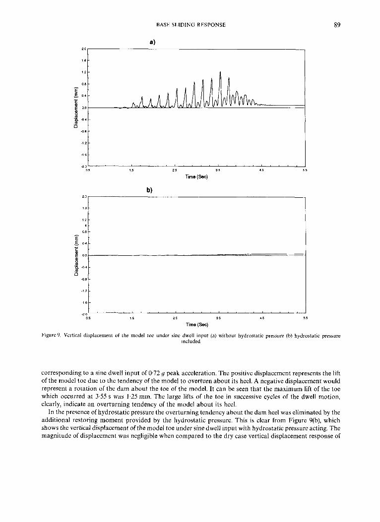
Looking at the overall results of various tests described above it seems that overturning about the toe of the dam section is improbable because the downstream sliding occurs before rotation about the toe could take place. This was observed in all the input cases and in both dry and wet tests. However, for dry tests the dam model showed a tendency to overturn about its heel at accelerations comparable to those required to slide it upstream. This tendency of upstream overturning, which is the direct effect of dam geometry, was most prominent under the sine dwell input. Figure 9(a) shows the vertical displacement of the toe, during a dry test,
BASE SLIDING RESPONSE
I
; D ' p 4 4 -
a . 4.8
-1 2
-1 6
-2 0
89
0 0 0
-
- -
4 8
-1 6
0 5 1 5 2 5 35 4 5 5 5
Time (Sec)
b) 20
08 I
E 0 4
corresponding to a sine dwell input of 0.72 g peak acceleration. The positive displacement represents the lift of the model toe due to the tendency of the model to overturn about its heel. A negative displacement would represent a rotation of the dam about the toe of the model. It can be seen that the maximum lift of the toe which occurred at 3.55 s was 1.25 mm. The large lifts of the toe in successive cycles of the dwell motion, clearly, indicate an overturning tendency of the model about its heel.
In the presence of hydrostatic pressure the overturning tendency about the dam heel was eliminated by the additional restoring moment provided by the hydrostatic pressure. This is clear from Figure 9(b), which shows the vertical displacement of the model toe under sine dwell input with hydrostatic pressure acting. The magnitude of displacement was negligible when compared to the dry case vertical displacement response of
90 R. A. MIR AND C. A. TAYLOR
the toe under a similar input (Figure 9(a)). This indicates very little overturning tendency about the heel. Similar trends were observed under other inputs.
Figure 9(a) shows an apparent residual displacement of about 0.1 mm of the dam toe during the dry test. This was actually due to a slight lateral displacement of the model which occurred during its upstream overturning and subsequent impacts on the base. A lateral displacement of the model would cause a change in magnetic field around the non-contacting displacement transducer in the horizontal plane, which would induce a slight error in the vertical displacement signal. The apparent residual displacement during the test including the hydrostatic pressure (Figure 9(b)) was the result of a large downstream sliding displacement, which again caused a slight change in the magnetic field of the vertical displacement transducer.
8. ANALYTICAL EVALUATION O F THE DYNAMIC SLIDING RESPONSE
One of the objectives of this study was to assess the validity of a typical contact surface algorithm6. in predicting the sliding response under dynamic loading, using a contact surface at the interface. This algorithm uses a Lagrange multiplier approach to evaluate sliding and separation response, between two bodies in contact, under static or dynamic loading conditions. An implicit time integration solution procedure is employed to solve the contact problem, in which the contact area may vary during the response history. The bodies in contact may be rigid or flexible, with Coulomb frictional conditions at the interface, and may undergo large deformations in repeated sliding and separation. The conditions of sliding, sticking or tension release in every equilibrium iteration during a time step are determined for every contact segment (an area bounded by two nodes in a 2-D contact surface). The current status of a node at the contact surface is then evaluated from a criterion based on the sliding, sticking or tension release status of its adjacent contact segments. This algorithm is implemented in the finite element program, SOLVIA (a derivative of the ADINA finite element program), which was used in this study.
8.1. Analytical model As full model similitude with the prototype was not maintained in the experiments, the experimental
sliding response would not represent a direct correlation with the results of a sliding response analysis of a prototype dam. Therefore, keeping in view the objective of the study, the analyses were performed on the experimental model itself so as to facilitate a direct comparison between the analytical and the experimental results. The input motions used in the analyses were the actual shaking table motions recorded during the tests.
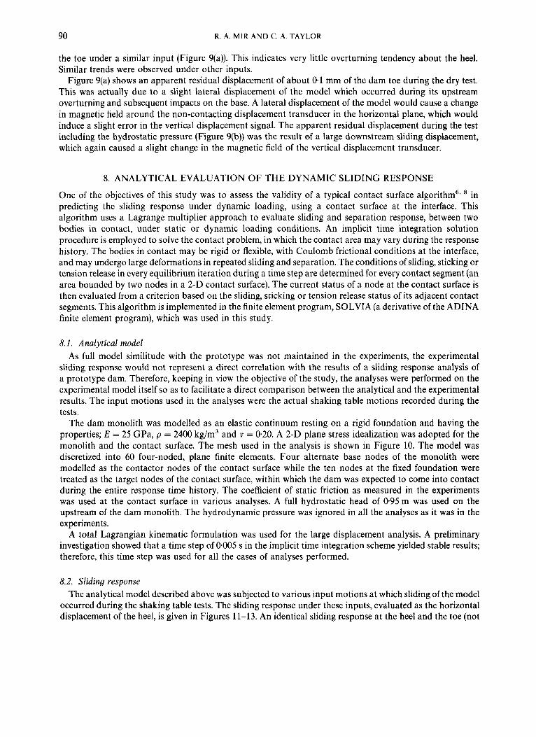
The dam monolith was modelled as an elastic continuum resting on a rigid foundation and having the properties; E = 25 GPa, p = 2400 kg/m3 and v = 0.20. A 2-D plane stress idealization was adopted for the monolith and the contact surface. The mesh used in the analysis is shown in Figure 10. The model was discretized into 60 four-noded, plane finite elements. Four alternate base nodes of the monolith were modelled as the contactor nodes of the contact surface while the ten nodes at the fixed foundation were treated as the target nodes of the contact surface, within which the dam was expected to come into contact during the entire response time history. The coefficient of static friction as measured in the experiments was used at the contact surface in various analyses. A full hydrostatic head of 0.95m was used on the upstream of the dam monolith. The hydrodynamic pressure was ignored in all the analyses as it was in the experiments.
A total Lagrangian kinematic formulation was used for the large displacement analysis. A preliminary investigation showed that a time step of 0405 s in the implicit time integration scheme yielded stable results; therefore, this time step was used for all the cases of analyses performed.
8.2. Sliding response The analytical model described above was subjected to various input motions at which sliding of the model
occurred during the shaking table tests. The sliding response under these inputs, evaluated as the horizontal displacement of the heel, is given in Figures 11-13. An identical sliding response at the heel and the toe (not

BASE SLIDING RESPONSE 91
Figure 10. Finite element mesh used for the sliding analyses
presented here) of the dam under the influence of various test inputs indicated that the dam monolith slid as a rigid body in all the cases.
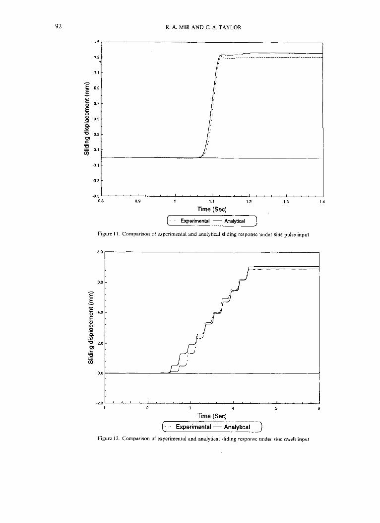
Figure 11 shows the sliding displacement predicted by the analysis under the sine pulse input. For a convenient comparison, the experimental sliding response is also shown in the same figure. It can be observed that the initiation of the slip and the magnitude of sliding displacements show a very good comparison.
Figure 12 shows the analytically evaluated sliding displacement response time history due to the sine dwell input which caused the sliding of the dam model during the test. The experimental displacement time history is superimposed on the same plot. As in the case of the test, it can be seen that downstream sliding occurred in ten successive peak cycles of the sine dwell motion. The instants of time at which the sliding in the various cycles occurred are almost identical in both the analytical and experimental plots. Except in the first few cycles, the magnitude of displacements in the successive cycles is also in a reasonable agreement. The net predicted and observed residual displacements are also reasonably close.
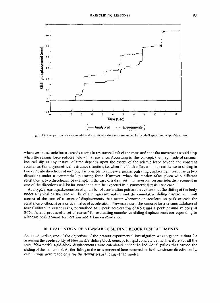
The sliding response time history evaluated from analysis under the EC-8 spectrum compatible motion is shown in Figure 13 along with the experimental response time history. Downstream slippage of the model as predicted by the analysis and observed in the test occurred at similar times although the magnitude of displacements under some of the peak pulses did not show a good agreement. The net residual downstream sliding displacement observed in the test was nearly same as that predicted by the analysis. The differences in the predicted and measured displacements probably arose as a result of the small out-of-plane accelerations that the physical model experienced due to cross-coupling of the shaking table axes and asymmetries in the model geometry. At the end of the tests, the model was observed to have twisted slightly in plan. This would have been sufficient to produce the differences (about 0.25 mm at the two major acceleration pulses) in the predicted and measured responses.
9. SLIDING BLOCK CONCEPT TO EVALUATE SEISMIC INDUCED SLIP
A method for evaluating seismic-induced slip in embankments and earth dams was introduced by New- mark.' It is based on the assumptions that a rigid mass is capable of displacement along a sliding surface
92 R. A. MIR A N D C. A. TAYLOR
0.8 0.9 1 1.1 1.2 1.3
Time (Sec)
Figure 11. Comparison of experimental and analytical sliding response under sine pulse input
6.0
h
E E v w
f 4.0
0 m v)
cn c
s - n 5 2.0
0 5 .-
0.0
-2.0
1.4
1 2 3 4 5 6
Time (Sec)
- - Experimental - Analytical
Figure 12. Comparison of experimental and analytical sliding response under sine dwell input
BASE SLIDING RESPONSE 93
I- Analytical - - Experimental)
Figure 13. Comparison of experimental and analytical sliding response under Eurocode-8 spectrum compatible motion
whenever the seismic force exceeds a certain resistance limit of the mass and that the movement would stop when the seismic force reduces below this resistance. According to this concept, the magnitude of seismic- induced slip at any instant of time depends upon the extent of the seismic force beyond the constant resistance. For a symmetrical resistance situation, i.e. when the block offers a similar resistance to sliding in two opposite directions of motion, it is possible to achieve a similar pulsating displacement response in two directions under a symmetrical pulsating force. However, when the motion takes place with different resistance in two directions, for example in the case of a dam with full reservoir on one side, displacement in one of the directions will be far more than can be expected in a symmetrical resistance case.
As a typical earthquake consists of a number of acceleration pulses, it is evident that the sliding of the body under a typical earthquake will be of a progressive nature and the cumulative sliding displacement will consist of the sum of a series of displacements that occur whenever an acceleration peak exceeds the resistance coefficient or a critical value of acceleration. Newmark used this concept for a seismic database of four Californian earthquakes, normalised to a peak acceleration of 0.5 g and a peak ground velocity of 0.76 m/s, and produced a set of curves9 for evaluating cumulative sliding displacements corresponding to a known peak ground acceleration and a known resistance.
10. EVALUATION OF NEWMARK'S SLIDING BLOCK DISPLACEMENTS
As stated earlier, one of the objectives of the present experimental investigation was to generate data for assessing the applicability of Newmark's sliding block concept to rigid concrete dams. Therefore, for all the tests, Newmark's rigid-block displacements were calculated under the individual pulses that caused the sliding of the dam model. As the sliding in the tests presented here occurred in the downstream direction only, calculations were made only for the downstream sliding of the model.
94 R . A. MIR AND C. A. TAYLOR
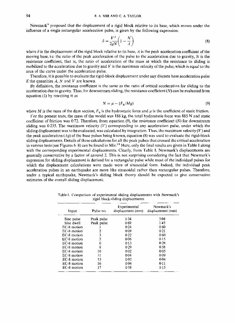
Newmark’ proposed that the displacement of a rigid block relative to its base, which moves under the influence of a single rectangular acceleration pulse, is given by the following expression:
where 6 is the displacement of the rigid block relative to its base, A is the peak acceleration coefficient of the moving base, i.e. the ratio of the peak acceleration of the pulse to the acceleration due to gravity, N is the resistance coefficient, that is, the ratio of acceleration of the mass at which the resistance to sliding is mobilized to the acceleration due to gravity and I/ is the maximum velocity of the pulse, which is equal to the area of the curve under the acceleration pulse.
Therefore, it is possible to evaluate the rigid-block displacement under any discrete base acceleration pulse if the quantities A, N and V are known.
By definition, the resistance coefficient is the same as the ratio of critical acceleration for sliding to the acceleration due to gravity. Thus, for downstream sliding, the resistance coefficient ( N ) can be evaluated from equation (1) by rewriting it as
N = c1 - (FII/MS) (9)
where M is the mass of the dam section, Fh is the hydrostatic force and p is the coefficient of static friction. For the present tests, the mass of the model was 186 kg, the total hydrostatic force was 885 N and static
coefficient of friction was 072. Therefore, from equation (9), the resistance coefficient ( N ) for downstream sliding was 0.235. The maximum velocity ( V ) corresponding to any acceleration pulse, under which the sliding displacement was to be evaluated, was calculated by integration. Thus, the maximum velocity ( V ) and the peak acceleration (Ag) of the base pulses being known, equation (8) was used to evaluate the rigid-block sliding displacements. Details of these calculations for all the peak pulses that crossed the critical acceleration in various tests (see Figures 6 8 ) can be found in Mir.” Here, only the final results are given in Table I along with the corresponding experimental displacements. Clearly, from Table I , Newmark’s displacements are generally conservative by a factor of around 2. This is not surprising considering the fact that Newmark’s expression for sliding displacement is derived for a rectangular pulse while most of the individual pulses for which the displacement calculations were made were of sinusoidal form. Indeed, the individual peak acceleration pulses in an earthquake are more like sinusoidal rather than rectangular pulses. Therefore, under a typical earthquake, Newmark’s sliding block theory should be expected to give conservative estimates of the overall sliding displacement.
Table I. Comparison of experimental sliding displacements with Newmark’s rigid block-sliding displacements
Experiment a1 Newmark‘s Input Pulse no. displacement (mm) displacement (mm)
Sine pulse Sine dwell
EC-8 motion EC-8 motion EC-8 motion EC-8 motion EC-8 motion EC-8 motion EC-8 motion EC-8 motion EC-8 motion EC-8 motion EC-8 motion
Peak pulse Peak pulse
1 2 3 5 6 8
10 11 15 16 17
1.34 0.69 0.24 009 022 006 013 0.29 002 004 002 0.04 0.58
3.04 1.43 0.60 0.2 1 0.60 0.15 0.28 0.58 0.05 0.09 0.04 0.11 1.15
BASE SLIDING RESPONSE 95
11. SIMPLE SLIP ANALYSIS BY INTEGRATION OF BASE ACCELERATION
The comparison of observed and calculated sliding displacements (Table 1) has shown that Newmark’s approach represents an upper bound on the sliding displacements and can predict values around two times the expected sliding displacements. The analytical results, on the other hand, have demonstrated that fairly accurate prediction of sliding displacements can be made by performing non-linear dynamic analyses using a step-by-step time integration procedure. However, such analyses are computationally expensive and require advanced numerical techniques to model an interface with capabilities of sticking, slipping and tension release between the bodies in contact.
As an alternative to Newmark’s approximate method and the expensive non-linear analytical approach, it is possible to obtain reasonable estimates of seismic-induced slip by integrating the absolute acceleration time histories of the ground and the rigid block. The acceleration time history of the block can be assumed to be the same as that of the base with its peaks clipped at the critical sliding acceleration level. This is the principle underlying the progressive failure model proposed by Richards and Elms’ for gravity retaining walls which assumes that the block acceleration remains unchanged as the base acceleration crosses the critical value. For a rigid block, it is reasonable to assume that the block and the base move with the same acceleration and have a zero relative velocity until the critical acceleration is reached. Once the base acceleration crosses the critical value, it is assumed that the acceleration of the block does not change and remains constant. This gives rise to a relative velocity between the base and the block which produces a relative displacement or sliding. When the base acceleration drops back to a value below critical, the velocities become equal and the whole system moves as one once again. This continues until another peak acceleration pulse of the earthquake is encountered and the block receives another lurch as the relative velocity becomes non-zero.
The above principle has been incorporated into a computer program, DSP,” which is the main digital signal processing program in use at the Bristol EERC. Using this program, the sliding response history of a rigid block can be obtained corresponding to any base acceleration time history if the resistance coefficient or the critical acceleration for sliding is known. The program can also evaluate time histories of relative and absolute block velocity and acceleration.
Figure 14(a) shows the sliding displacement time history, evaluated using DSP, under the influence of the sine pulse input that caused the slippage in the test. For a convenient comparison, the experimental response under the same input is also shown in the figure. It can be seen that a reasonable agreement between the two plots exist. The magnitude of maximum sliding displacement evaluated by using DSP is 1.52 mm which is in a good agreement with the experimental value of 1-34 mm. Figure 14(b) shows the comparison of experi- mental and DSP predicted sliding responses under the influence of the sine dwell input that caused the slippage during the shaking table test. A cumulative sliding displacement of 6.65 mm was predicted by DSP which compared well with the observed cumulative displacement of 6.9 mm shown in the same figure.
The above results have indicated that rigid block sliding displacements can be predicted reasonably by performing a simple integration analysis of the earthquake time history. However, if the dynamic response of the dam during an earthquake is significant, the use of a non-linear large displacement analysis may be more appropriate.
12. CONCLUSIONS
Several simplifying assumptions made in the experimental work, particularly the existence of a full crack at the dam-foundation interface, should be recognized while drawing any conclusions from the results presented herein. These assumptions limit the scope of the test results in having a direct, quantitative, correlation with prototype dams. However, a useful insight into the dynamically induced sliding and overturning instability of concrete gravity dams was provided by the experimental results. Important findings were also made from the analytical and theoretical modelling of the experiments. Before discussing the general conclusions that may be drawn from this study, it is appropriate to consider further the implications of some of the simplifying assumptions.

96 R . A. MIR AND C. A. TAYLOR
_. . 0.00 0.90 1 .00 1.10 1.20 1.30 1.40
Time (sec)
".V ,
0.00 1 .00 2.00 3.00 4.00 5.00 6.00
Time (sec)
Figure 14. Comparison of experimental sliding response with the response evaluated using a simple rigid-block slip analysis (a) sine pulse input (b) sine dwell input
The focus of this study were low-to-medium height gravity dams, around 3 M 0 m high, which are common in the U.K. and worldwide. In general, dams of this height have relatively high fundamental frequencies, of the order of 8-10Hz, which tend to be outside the dominant frequency range of most earthquakes. Their dynamic response is likely to be significantly less than that of taller dams, tending more towards a rigid body response (although this will depend on the nature of the earthquake experienced). Therefore, the use of a rigid dam model and relatively low frequency input motions is considered a reasonable
BASE SLIDING RESPONSE 97
simplification for this study. For dams of this height, the natural frequencies of the reservoir and dam are usually sufficiently separated for water compressibility effects to be neglected. Hydrodynamic loads therefore can be modelled adequately by a simple added mass approach. The additional horizontal driving forces arising from the added mass can be calculated easily if necessary.21 For simplicity, they were neglected in the present study.
Increasing foundation flexibility tends to reduce the overall dynamic response of the dam-foundation system,” thereby reducing the forces experienced by the dam itself. It is these forces that drive the sliding and overturning mechanisms. On the other hand, the forces resisting sliding are dependent on the mechanical strength of the rock and concrete, including the coefficient of friction. For the purpose of this study of relatively simple analytical approaches with horizontal ground motions only, any variation in these strength characteristics, due to the dynamic response of the dam system, reasonably can be neglected or, if necessary, catered for by some estimated safety factor. Similarly, the resistance to overturning is essentially due to the restoring moments generated by the dead weight of the dam, which is not influenced by the response of the dam. Therefore, the limits that the driving forces must exceed to initiate sliding or overturning are effectively independent of the driving forces. The magnitude of the driving forces, however, will be affected by factors such as the hydrodynamic forces and foundation flexibility.
Vertical ground motions were not considered in this study. If included, they would alter the driving forces experienced by the dam and affect the frictional resistance to sliding by changing the force acting normal to the sliding plane. In general, the vertical natural frequencies of a gravity dam are much higher than the dominant frequencies of an earthquake and, therefore, a dam on a rigid foundation will tend to respond as a rigid body to vertical motions. The effects of vertical motions could be approximated by adjusting the vertical gravity forces in the various calculation procedures.
General conclusions drawn from the study are as follows:
(i) With the full hydrostatic pressure acting on the dam, the resistance to downstream sliding is reduced considerably and, therefore, the sliding in the downstream direction can occur at accelerations much lower than those at which the sliding in the upstream direction or overturning in the downstream or upstream direction could be expected. Therefore, under full reservoir conditions, downstream sliding can be considered to be the only significant stability failure of a concrete gravity dam.
(ii) In light of the experimental findings, the chances of a dam of normal geometry to overturn about its toe may be considered to be remote if the uplift pressures are not significant. However, experiments under the empty reservoir conditions indicated that the dam can have a tendency to overturn upstream about its heel before it can slide in that direction. This is because of the fact that the critical acceleration to initiate upstream overturning of the dam can be lower than that required to cause upstream sliding, particularly when the frictional resistance at the dam-foundation interface is high. However, because of the short duration of acceleration pulses in an earthquake, a complete instability due to overturning of the dam about its heel is unlikely.
(iii) In general, Newmark’s sliding block displacements under various inputs were about two times higher than the observed experimental displacements. The reason for this discrepancy is that Newmark’s theory assumes sliding to occur under the influence of a rectangular base acceleration pulse while the pulses considered in this study were generally of a sinusoidal nature. In a real earthquake, as the individual pulses are more of sinusoidal than rectangular form, Newmark’s approach may represent an upper bound on the sliding displacements. However, considering the ease with which it can be applied, it is possible to adapt Newmark’s approach for rigid gravity dams in order to obtain conservative estimates of seismic-induced slip, if the resistance to sliding is reasonably modelled or evaluated.
(iv) The analytically evaluated sliding response using a typical finite element contact surface algorithm showed an adequate agreement with the experimental results. This indicates that such an algorithm can be used with confidence to perform sliding analyses of prototype darns under seismic loading.
(v) If the dynamic response of the dam is not significant, a simple rigid block slip analysis can be an effective alternative to the expensive dynamic analysis. Such an analysis involves the integration of the

98 R. A. MIR AND C. A. TAYLOR
absolute base and block acceleration time histories to obtain the relative velocity and thus the relative displacement between the base and the rigid block. Using this approach, a good approximation of the measured sliding responses under various test inputs was achieved.
ACKNOWLEDGEMENTS
The authors are grateful for the financial support of the U.K. Engineering and Physical Sciences Research Council (EPSRC) and the Association of Commonwealth Universities.
REFERENCES
1. A. K. Chopra, ’Earthquake behaviour of reservoir-dam systems’, J . eng. mech. din, ASCE 94, 1475-1500 (1968). 2. U.S. Bureau of Reclamation ‘Design of small dams’, U.S. Government Printing Ofice, Washington, D.C., 1975. 3. U.S. Bureau of Reclamation ‘Design of gravity dams’, Design Manual for Concrete Gravity Dams, Denver, Colorado, 1976. 4. P. Leger and M. Katsouli, ‘Seismic stability of concrete gravity dams’, Earthquake eng. struct. dyn. 18, 889-902 (1989). 5. A. K. Chopra and L. Zhang, ‘Base sliding response of concrete gravity dams to earthquakes’, Report No . UCEIEERC 91/05,
6. SOLVIA Engineering, AB, ‘SOLVIA-PRE 9 G U s e r manual for stress analysis’, Report No . SE 90-1, 1990. 7. SOLVIA Engineering, AB, ‘SOLVIA-POST 9 G U s e r s manual for display and post-processing of SOLVIA and SOLVIA-TEMP
8. SOLVIA Engineering, AB, ‘SOLVIA-PRE and SOLVIA-POST-New capabilities in version 90.2’ User manual, 1992. 9. N. M. Newmark, ‘Effects of earthquakes on dams and embankments’, Geotechnique 15, 139-160 (1965).
Earthquake Engineering Research Centre, University of California, Berkeley, 1991.
results’, Report No. S E 90-2, 1990.
10. J.-S. Lin and R. V. Whitman, ‘Earthquake induced displacements of sliding blocks’, J . geotech. eng. ASCE 112, 44-59 (1986). 11. J . 4 . Lin and R. V. Whitman, ‘Decoupling approximation to the evaluation of earthquake-induced plastic slip in earth dams’,
12. Y. Ishiyama, ‘Motions of rigid bodies and criteria for overturning by earthquake excitation’, Earthquake eng. struct. dyn. 10,653650
13. W. E. Daniell, R. A. Mir, M. Simic and C. A. Taylor, ‘Seismic behaviour of concrete gravity dams’, Proc. 10th Eur. con5 on earthq.
14. C. A. Taylor, W. E. Daniell, R. A. Mir, M. Simic and J. Hinks, ‘The behaviour of gravity dams in the areas of low seismicity’, British
15. R. Richards and D. G. Elms, ‘Seismic behaviour of gravity retaining walls’, J . geotech. eng. din, ASCE 105, 449464 (1979). 16. Commission of the European Communities ‘Eurocode No 8, Structures in Seismic Regions-Design, Part 1, General and Building’,
17. J. M. W. Brownjohn, E. J. Greeves and C. A. Taylor, ‘Quality assurance of experimental and research activities in a university
18. A. Blakeborough, R. T. Severn and C. A. Taylor, ‘The new UK national six-axis earthquake shaking table’, Proc. 8th Eur. conf on
19. R. A. Mir, ‘An experimental investigation into the seismic induced failure of moderately high concrete gravity dams’, PhD. thesis,
20. C. A. Taylor, ‘DSP-A fully interactive digital signal processing program-reference manual, version 1.36‘, Report No. UBCE-EE-
21. H. M. Westergaard, ‘Water pressures on dams during earthquakes’, Trans. ASCE 98,413433 (1933). 22. M. Simic, ‘Earthquake analysis of concrete gravity dam-foundation systems’, Ph.D. thesis, Department of Civil Engineering,
Earthquake eng. struct. dyn. 11, 667-678 (1983).
(1982).
eng., Vienna, Austria, 3, 1951-1955, 1994.
Dam Soc. Conf, Exeter, U.K., 1994.
Commission of the European Communities, Luxembourg, 1988.
environment’, Proc. inst. civ. engrs., civil engineering 1, 3947 (1992).
earthq. eng., Lisbon, Portugal, 1986.
Department of Civil Engineering, University of Bristol, U.K., 1994.
94-20, Earthquake Engineering Research Centre, Department of Civil Engineering, University of Bristol, U.K., 1994.
University of Bristol, U.K., 1994.