an inverse approach for interturn fault detection in ...users.ugent.be/~ldupre/2016_3.pdfmahmoud et...
TRANSCRIPT
226 IEEE TRANSACTIONS ON INDUSTRY APPLICATIONS, VOL. 52, NO. 1, JANUARY/FEBRUARY 2016
An Inverse Approach for Interturn Fault Detectionin Asynchronous Machines Using Magnetic
Pendulous Oscillation TechniqueHanafy Mahmoud, Student Member, IEEE, Ahmed Abou-Elyazied Abdallh, Member, IEEE,
Nicola Bianchi, Fellow, IEEE, S. M. El-Hakim, Adel Shaltout, and Luc Dupré, Member, IEEE
Abstract—In this paper, a coupled experimental–mathematicalinverse problem based methodology for the detection of interturnfaults in an asynchronous induction machine is presented. Thefault detection is accomplished by interpreting well-defined mea-surements into the machine mathematical model. First, the studiedmachine is modeled by means of a dynamic state-space modelin the abc reference frame. This model simulates the machinebehavior under healthy and faulty cases in both transient andsteady-state conditions. The signature of the interturn fault iscaptured using the magnetic pendulous oscillation technique. Theproposed inverse problem is validated numerically and experi-mentally. The results show the robustness of the proposed schemeagainst the measurement noise.
Index Terms—Asynchronous machines, condition monitoring,interturn fault, inverse problem, magnetic pendulous oscillation(MPO) technique.
I. INTRODUCTION
A SYNCHRONOUS induction machines are widely usedin industrial applications due to their high torque and
power specifications [1]. It is well known that induction motorsare highly reliable; however, they are susceptible to severalfault types [2], [3]. Although the machine performance analy-sis under different electrical faults, e.g., stator winding and
Manuscript received April 13, 2015; revised July 2, 2015; acceptedAugust 25, 2015. Date of publication September 15, 2015; date of currentversion January 18, 2016. Paper 2015-EMC-0217.R1, presented at the 2015IEEE Workshop on Electrical Machines Design, Control and Diagnosis, Torino,Castello del Valentino, Italy, March 26–27, and approved for publication inthe IEEE TRANSACTIONS ON INDUSTRY APPLICATIONS by the ElectricMachines Committee of the IEEE Industry Applications Society.
H. Mahmoud is with the Department of Industrial Engineering, University ofPadova, 35131 Padova, Italy, and also with the Department of Electrical Powerand Machines, Cairo University, 12613 Giza, Egypt (e-mail: [email protected]).
A. A.-E. Abdallh is with the Department of Electrical Energy, Systems, andAutomation, Ghent University, 9052 Ghent, Belgium, and also with the Depart-ment of Electrical Power and Machines, Cairo University, 12613 Giza, Egypt(e-mail: [email protected]).
N. Bianchi is with the Department of Industrial Engineering, University ofPadova, 35131 Padova, Italy (e-mail: [email protected]; [email protected]).
S. M. El-Hakim and A. Shaltout are with the Department of Electrical Powerand Machines, Cairo University, 12613 Giza, Egypt (e-mail: [email protected]; [email protected]).
L. Dupré is with the Department of Electrical Energy, Systems, and Automa-tion, Ghent University, 9052 Ghent, Belgium (e-mail: [email protected]).
Color versions of one or more of the figures in this paper are available onlineat http://ieeexplore.ieee.org.
Digital Object Identifier 10.1109/TIA.2015.2478882
broken bar faults, and mechanical faults, e.g., bearing andeccentricity faults, was extensively studied in literature [4]–[8],it still attracts attention of ongoing research projects around theworld [9]–[11].
In practice, damage of stator winding insulation is one of themost frequent failures in induction machines. In [12], it wasreported that the occurrence of the winding faults, specificallythe interturn fault, varies between 30% and 40% of the totalpossible faults. Therefore, it is essential to detect this fault typeat an early stage in order to prevent the development of severefault mechanisms [13].
In this paper, we present a diagnosis technique to detectthe interturn fault in induction motors. The diagnosis algo-rithm is based on solving a coupled experimental–mathematicalinverse problem [14]. This inverse problem utilizes an effi-cient dynamic state-space model of the three-phase inductionmotor [15].
This model analyzes the transient, as well as the steady-state,performances of the motor under both healthy and faulty cases.The main performance parameters, such as the electromagnetictorque, the speed, the stator winding currents, and the faultcurrent, have been studied under different fault percentages andloading conditions, which were not included in [15]. At faultyconditions, the motor shows a magnetic pendulous oscillation(MPO) phenomenon [16], which is used to infer the interturnfault via the inverse problem. Since the MPO phenomenonalso appears for different types of faults [16], such as brokenbars and unbalanced supply faults, this work focuses only oninterturn faults.
In fact, the MPO detection technique is mainly based onthe space vectors of the stator current and voltage. Therefore,the model proposed in [15] is utilized here to provide themathematical “simulation” results that can be used to detectthe interturn fault using the proposed inverse approach. To thebest of the authors’ knowledge, this issue has not been fullyinvestigated in literature yet. In order to validate the inverseapproach, both numerical and experimental measurements, atdifferent faulty conditions, are carried out.
In the subsequent section, the dynamic state-space modelis described [15]. The model performance with a detaileddescription about the MPO is also given. Section III describesthe inverse problem formulation, followed by numerical andexperimental validation results in Section IV. Finally, the con-clusion is drawn in Section V.
0093-9994 © 2015 IEEE. Personal use is permitted, but republication/redistribution requires IEEE permission.See http://www.ieee.org/publications_standards/publications/rights/index.html for more information.
MAHMOUD et al.: INVERSE APPROACH FOR INTERTURN FAULT DETECTION IN ASYNCHRONOUS MACHINES 227
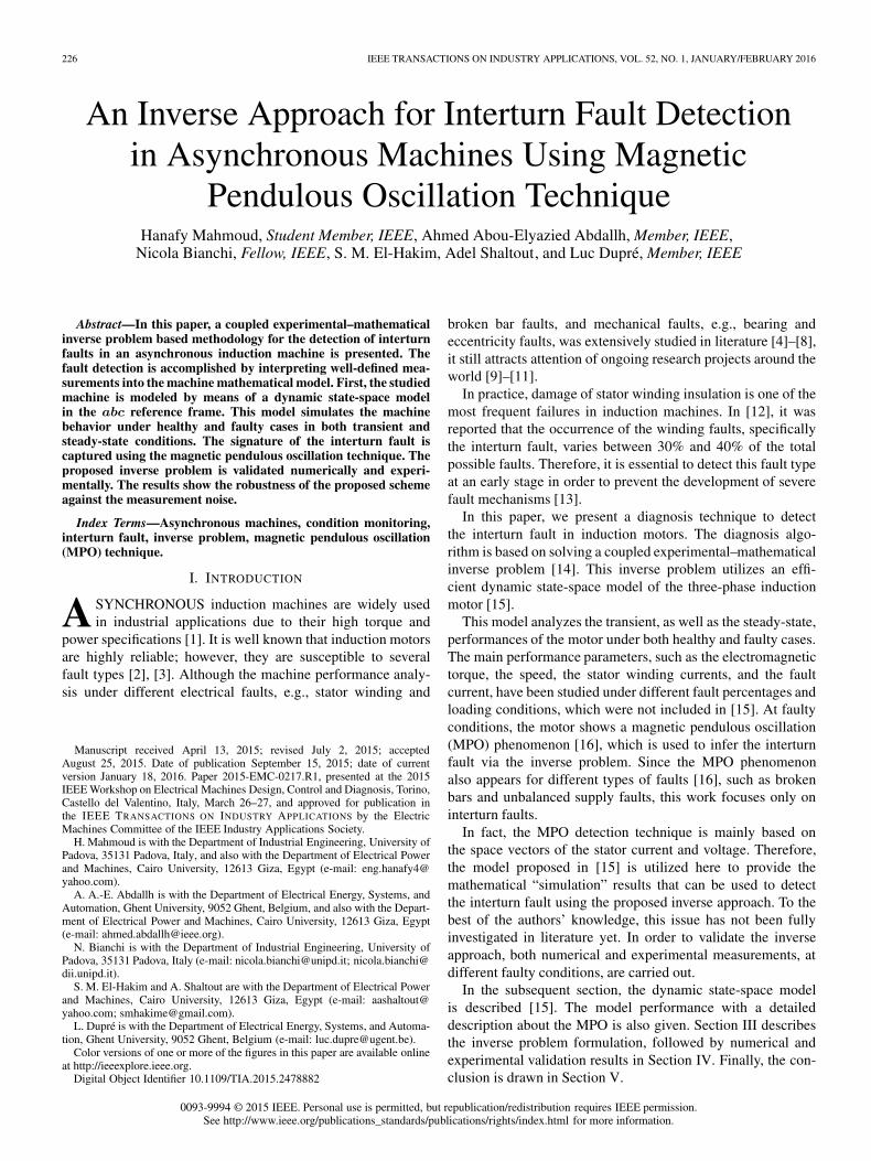
Fig. 1. Representation of a three-phase induction motor with interturn faultywindings.
II. FORWARD MODEL
A. Dynamic State-Space Model
In this section, the dynamic state-space model of adistributed-winding three-phase induction motor under inter-turn fault condition is presented. The model is based on theone presented in [15]. This model computes the three-phasecurrents of the stator and rotor, the electromagnetic torque,and the rotor speed for a given supply voltage. Fig. 1 showsthe three-phase windings of the stator and rotor in the abcreference frame, where the axis of stator phase a is chosen asthe reference axis. The interturn fault is assumed to occur onlyin phase a, and the other two phases, i.e., b and c, are kepthealthy. The mutual inductances (L) between any two phasesi, j of the stator and/or rotor can be computed as
Li,j = L◦ cos (θd(i, j)) (1)
where θd(i, j) is the difference between the ith and jth phaseangles with respect to the reference frame and L◦ is the maxi-mum mutual inductance.
As it is clear from Fig. 1, phase a is split into two phases,namely, as1 and as2. Hence, the inductance matrix can becomputed as
L =
[Lss Lsr
Lrs Lrr
](2)
where Lss represents the mutual inductances between the statorwindings and it is given by
Lss = Lsl
⎡⎢⎢⎣(1− μ)2 0 0 0
0 μ 0 00 0 0 00 0 0 0
⎤⎥⎥⎦
+ L◦
⎡⎢⎢⎣
(1− μ)2 μ(1 − μ) −0.5(1− μ) −0.5(1− μ)μ(1− μ) μ2 −0.5μ −0.5μ
−0.5(1− μ) −0.5μ 1 −0.5−0.5(1− μ) −0.5μ −0.5 1
⎤⎥⎥⎦
(3)
with μ being the percentage of the shorted turns to the totalturns of the faulty phase. Lsl is the leakage inductance of the
stator winding. Notice that the angle between phases in thedistributed-winding scheme is ±120◦. Similarly, Lrr representsthe mutual inductances between the rotor windings
Lrr =
⎡⎣Lrl + L◦ −0.5L◦ −0.5L◦−0.5L◦ Lrl + L◦ −0.5L◦−0.5L◦ −0.5L◦ Lrl + L◦
⎤⎦ (4)
where Lrl is the leakage inductance of the rotor winding.Lsr and Lrs represent the mutual inductances between the
stator and rotor windings
Lsr = L◦
⎡⎢⎢⎣(1−μ) cos(θ) (1−μ) cos(θ+120) (1−μ) cos(θ−120)
μ cos(θ) μ cos(θ+120) μ cos(θ−120)
cos(θ−120) cos(θ) cos(θ+120)
cos(θ+120) cos(θ−120) cos(θ)
⎤⎥⎥⎦
(5)
Lrs = LTsr (6)
where θ is the rotor position in electrical degrees.The resistances of the stator and rotor windings can be also
presented in a matrix form as
R =
⎡⎢⎢⎢⎢⎢⎢⎢⎢⎣
(1− μ)Rs 0 0 0 0 0 00 μRs 0 0 0 0 00 0 Rs 0 0 0 00 0 0 Rs 0 0 00 0 0 0 Rr 0 00 0 0 0 0 Rr 00 0 0 0 0 0 Rr
⎤⎥⎥⎥⎥⎥⎥⎥⎥⎦
(7)
where Rs and Rr are the resistances per phase for the stator androtor windings, respectively.
The stator and rotor three-phase currents (I) can be com-puted by solving the motor voltage balance equation
V = RI + ωdL
dθI + L
dI
dt(8)
where
V = [Vas1Vas2
Vbs Vcs 0 0 0]T
I = [Ias1Ias2
Ibs Ics IarIbr Icr ]
T
where Vas1, Vas2
, Vbs , and Vcs are the voltage on the healthypart of phase a, shorted part of phase a, phase b, and phase c,respectively. ω is the electrical rotational speed. Additionally,referring to Fig. 1, Vas2
is equal to IfRf , where If is thefault current and Rf is the fault resistance. It is worth notingthat the value of Rf is high in the early stage of the fault andcontinuously decreases depending on the fault severity.
Hence, the electromagnetic torque is given by
T =p
2IT
dL
dθI (9)
with p being the number of pair poles.Consequently, the electrical rotational speed (ω) and rotor
position in electrical degrees (θ) can be computed from the
228 IEEE TRANSACTIONS ON INDUSTRY APPLICATIONS, VOL. 52, NO. 1, JANUARY/FEBRUARY 2016
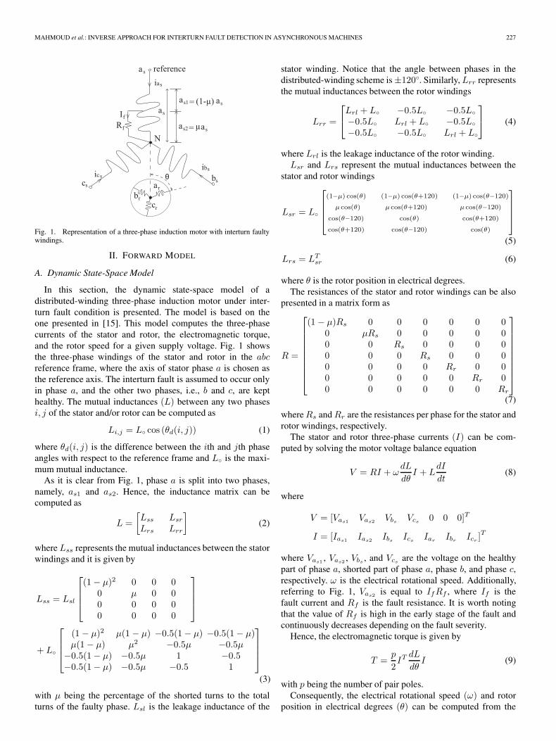
Fig. 2. Transient and steady-state torque behaviors for the studied three-phaseinduction motor with 10% and 50% stator winding interturn faults under no-load condition. (a) 10% interturn fault. (b) 50% interturn fault.
following mechanical balance equation:
T = Jdωm
dt+ TL +Bmωm (10)
ω =
∫p
[T − TL
J− Bmω_m
J
]dt, θ =
∫ωdt (11)
where TL, ωm, J , and Bm are the load torque, mechanicalrotational speed, moment of inertia, and friction coefficient,respectively.
B. Model Performance
Although the aforementioned model is based on the onepresented in [15], the motor performance under healthy andfaulty conditions has not been deeply presented in literature.Therefore, this section shows the results of the aforementionedmodel at different percentages of the interturn fault and loadingconditions. Specifically, we studied the effect of the interturnfault on the torque and speed behaviors, as well as on the statorcurrents. These results are obtained for motor-A, whose dataare given in the Appendix.
Fig. 2 shows the transient and steady-state electromagnetictorque at the no-load condition for healthy and faulty cases,with 10% and 50% interturn faults. From Fig. 2, it is clear thatthe interturn fault results in a torque ripple; the higher the faultpercentage, the higher the torque ripple.
In addition, the effect of the interturn fault on the electromag-netic torque under different loading conditions is investigated.Fig. 3 depicts the torque behavior at a half full load casestudy. By increasing the load torque, the phase current and,consequently, fault current are increased. Therefore, the impactof the fault current is increased, which results in higher torqueripples. This is noticeable by comparing Fig. 3 with Fig. 2.
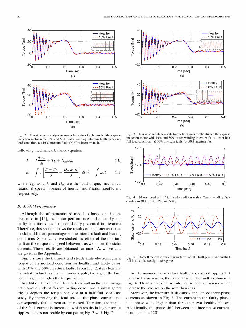
Fig. 3. Transient and steady-state torque behaviors for the studied three-phaseinduction motor with 10% and 50% stator winding interturn faults under halffull load condition. (a) 10% interturn fault. (b) 50% interturn fault.
Fig. 4. Motor speed at half full load condition with different winding faultconditions (0%, 10%, 30%, and 50%).
Fig. 5. Stator three-phase current waveforms at 10% fault percentage and halffull load, at the steady-state regime.
In like manner, the interturn fault causes speed ripples thatincrease by increasing the percentage of the fault as shown inFig. 4. These ripples cause rotor noise and vibrations whichincrease the stresses on the rotor bearings.
Moreover, the interturn fault causes unbalanced three-phasecurrents as shown in Fig. 5. The current in the faulty phase,i.e., phase a, is higher than the other two healthy phases.Additionally, the phase shift between the three-phase currentsis not equal to 120◦.
MAHMOUD et al.: INVERSE APPROACH FOR INTERTURN FAULT DETECTION IN ASYNCHRONOUS MACHINES 229
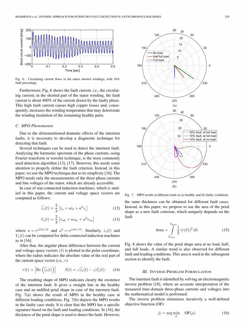
Fig. 6. Circulating current flows in the stator shorted windings, with 10%fault percentage.
Furthermore, Fig. 6 shows the fault current, i.e., the circulat-ing current; in the shorted part of the stator winding, the faultcurrent is about 400% of the current drawn by the faulty phase.This high fault current causes high copper losses and, conse-quently, increases the winding temperature that may deterioratethe winding insulation of the remaining healthy parts.
C. MPO Phenomenon
Due to the aforementioned dramatic effects of the interturnfaults, it is necessary to develop a diagnostic technique fordetecting that fault.
Several techniques can be used to detect the interturn fault.Analyzing the harmonic spectrum of the phase currents, usingFourier transform or wavelet technique, is the most commonlyused detection algorithm [13], [17]. However, this needs someattention to properly define the fault criterion. Instead, in thispaper, we use the MPO technique due to its simplicity [16]. TheMPO needs only the measurements of the three-phase currentsand line voltages of the stator, which are already accessible.
In case of star-connected induction machines, which is stud-ied in this paper, the current and voltage space vectors arecomputed as follows:
�is(t) =2
3
[ia + aib + a2ic
](12)
�vs(t) =2
3
[vab + avbc + a2vca
](13)
where a = ej(2π/3) and a2 = ej(4π/3). Similarly, is(t) andVs(t) can be computed for delta-connected induction machinesas in [16].
After that, the angular phase difference between the currentand voltage space vectors (δ) is plotted in the polar coordinate,where the radius indicates the absolute value of the real part ofthe current space vector (i.e., r)
r(t) =∣∣∣Re(�is(t)
)∣∣∣ δ(t) = ∠�is(t)− ∠�vs(t). (14)
The resulting shape of MPO indicates clearly the existenceof the interturn fault. It gives a straight line in the healthycase and an unfilled petal shape in case of the interturn fault.Fig. 7(a) shows the result of MPO in the healthy case atdifferent loading conditions. Fig. 7(b) depicts the MPO resultsin the faulty case study. It is clear that the MPO has a specificsignature based on the fault and loading conditions. In [16], thethickness of the petal shape is used to detect the fault. However,
Fig. 7. MPO results at different loads in (a) healthy and (b) faulty conditions.
the same thickness can be obtained for different fault cases.Instead, in this paper, we propose to use the area of the petalshape as a new fault criterion, which uniquely depends on thefault
Area =
δmax∫δmin
1
2(r(δ))2 dδ. (15)
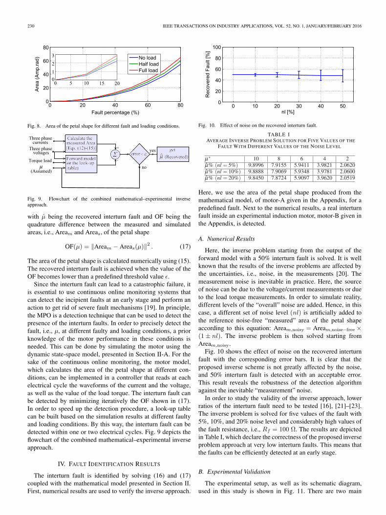
Fig. 8 shows the value of the petal shape area at no load, half,and full loads. A similar trend is also observed for differentfault and loading conditions. This area is used in the subsequentsection to identify the fault.
III. INVERSE PROBLEM FORMULATION
The interturn fault is identified by solving an electromagneticinverse problem [18], where an accurate interpretation of themeasured time-domain three-phase currents and voltages intothe mathematical model is performed.
The inverse problem minimizes iteratively a well-definedobjective function (OF)
μ̂ = argminμ
OF(μ) (16)
230 IEEE TRANSACTIONS ON INDUSTRY APPLICATIONS, VOL. 52, NO. 1, JANUARY/FEBRUARY 2016
Fig. 8. Area of the petal shape for different fault and loading conditions.
Fig. 9. Flowchart of the combined mathematical–experimental inverseapproach.
with μ̂ being the recovered interturn fault and OF being thequadrature difference between the measured and simulatedareas, i.e., Aream and Areas, of the petal shape
OF(μ) = ‖Aream − Areas(μ)‖2 . (17)
The area of the petal shape is calculated numerically using (15).The recovered interturn fault is achieved when the value of theOF becomes lower than a predefined threshold value ε.
Since the interturn fault can lead to a catastrophic failure, itis essential to use continuous online monitoring systems thatcan detect the incipient faults at an early stage and perform anaction to get rid of severe fault mechanisms [19]. In principle,the MPO is a detection technique that can be used to detect thepresence of the interturn faults. In order to precisely detect thefault, i.e., μ, at different faulty and loading conditions, a priorknowledge of the motor performance in these conditions isneeded. This can be done by simulating the motor using thedynamic state-space model, presented in Section II-A. For thesake of the continuous online monitoring, the motor model,which calculates the area of the petal shape at different con-ditions, can be implemented in a controller that reads at eachelectrical cycle the waveforms of the current and the voltage,as well as the value of the load torque. The interturn fault canbe detected by minimizing iteratively the OF shown in (17).In order to speed up the detection procedure, a look-up tablecan be built based on the simulation results at different faultyand loading conditions. By this way, the interturn fault can bedetected within one or two electrical cycles. Fig. 9 depicts theflowchart of the combined mathematical–experimental inverseapproach.
IV. FAULT IDENTIFICATION RESULTS
The interturn fault is identified by solving (16) and (17)coupled with the mathematical model presented in Section II.First, numerical results are used to verify the inverse approach.
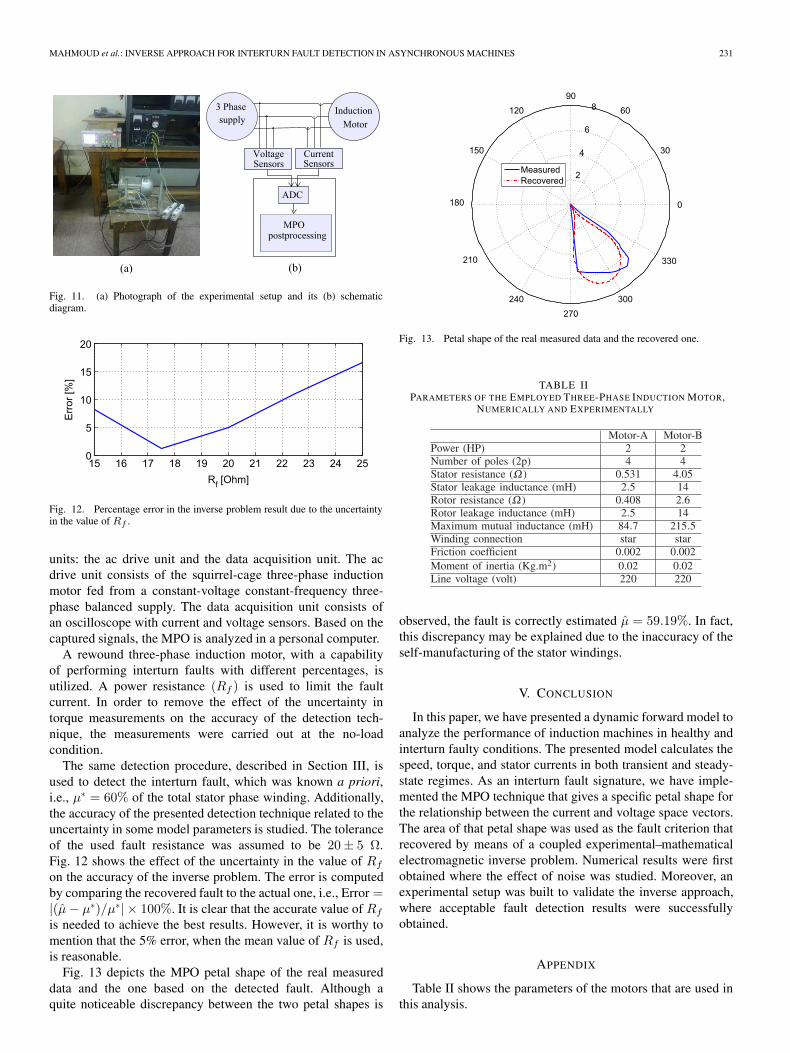
Fig. 10. Effect of noise on the recovered interturn fault.
TABLE IAVERAGE INVERSE PROBLEM SOLUTION FOR FIVE VALUES OF THE
FAULT WITH DIFFERENT VALUES OF THE NOISE LEVEL
Here, we use the area of the petal shape produced from themathematical model, of motor-A given in the Appendix, for apredefined fault. Next to the numerical results, a real interturnfault inside an experimental induction motor, motor-B given inthe Appendix, is detected.
A. Numerical Results
Here, the inverse problem starting from the output of theforward model with a 50% interturn fault is solved. It is wellknown that the results of the inverse problems are affected bythe uncertainties, i.e., noise, in the measurements [20]. Themeasurement noise is inevitable in practice. Here, the sourceof noise can be due to the voltage/current measurements or dueto the load torque measurements. In order to simulate reality,different levels of the “overall” noise are added. Hence, in thiscase, a different set of noise level (nl) is artificially added tothe reference noise-free “measured” area of the petal shapeaccording to this equation: Aream,noisy = Aream,noise−free ×(1± nl). The inverse problem is then solved starting fromAream,noisy.
Fig. 10 shows the effect of noise on the recovered interturnfault with the corresponding error bars. It is clear that theproposed inverse scheme is not greatly affected by the noise,and 50% interturn fault is detected with an acceptable error.This result reveals the robustness of the detection algorithmagainst the inevitable “measurement” noise.
In order to study the validity of the inverse approach, lowerratios of the interturn fault need to be tested [16], [21]–[23].The inverse problem is solved for five values of the fault with5%, 10%, and 20% noise level and considerably high values ofthe fault resistance, i.e., Rf = 100 Ω. The results are depictedin Table I, which declare the correctness of the proposed inverseproblem approach at very low interturn faults. This means thatthe faults can be efficiently detected at an early stage.
B. Experimental Validation
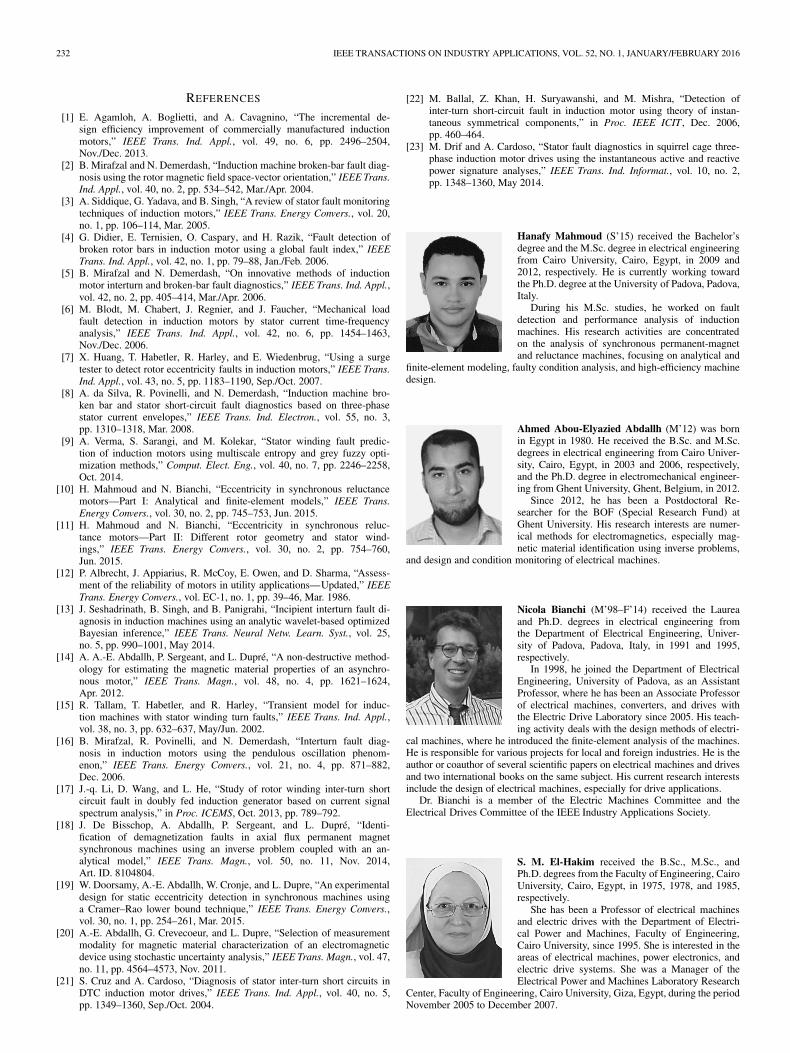
The experimental setup, as well as its schematic diagram,used in this study is shown in Fig. 11. There are two main
MAHMOUD et al.: INVERSE APPROACH FOR INTERTURN FAULT DETECTION IN ASYNCHRONOUS MACHINES 231
Fig. 11. (a) Photograph of the experimental setup and its (b) schematicdiagram.
Fig. 12. Percentage error in the inverse problem result due to the uncertaintyin the value of Rf .
units: the ac drive unit and the data acquisition unit. The acdrive unit consists of the squirrel-cage three-phase inductionmotor fed from a constant-voltage constant-frequency three-phase balanced supply. The data acquisition unit consists ofan oscilloscope with current and voltage sensors. Based on thecaptured signals, the MPO is analyzed in a personal computer.
A rewound three-phase induction motor, with a capabilityof performing interturn faults with different percentages, isutilized. A power resistance (Rf ) is used to limit the faultcurrent. In order to remove the effect of the uncertainty intorque measurements on the accuracy of the detection tech-nique, the measurements were carried out at the no-loadcondition.
The same detection procedure, described in Section III, isused to detect the interturn fault, which was known a priori,i.e., μ∗ = 60% of the total stator phase winding. Additionally,the accuracy of the presented detection technique related to theuncertainty in some model parameters is studied. The toleranceof the used fault resistance was assumed to be 20± 5 Ω.Fig. 12 shows the effect of the uncertainty in the value of Rf
on the accuracy of the inverse problem. The error is computedby comparing the recovered fault to the actual one, i.e., Error =|(μ̂− μ∗)/μ∗| × 100%. It is clear that the accurate value of Rf
is needed to achieve the best results. However, it is worthy tomention that the 5% error, when the mean value of Rf is used,is reasonable.
Fig. 13 depicts the MPO petal shape of the real measureddata and the one based on the detected fault. Although aquite noticeable discrepancy between the two petal shapes is
Fig. 13. Petal shape of the real measured data and the recovered one.
TABLE IIPARAMETERS OF THE EMPLOYED THREE-PHASE INDUCTION MOTOR,
NUMERICALLY AND EXPERIMENTALLY
observed, the fault is correctly estimated μ̂ = 59.19%. In fact,this discrepancy may be explained due to the inaccuracy of theself-manufacturing of the stator windings.
V. CONCLUSION
In this paper, we have presented a dynamic forward model toanalyze the performance of induction machines in healthy andinterturn faulty conditions. The presented model calculates thespeed, torque, and stator currents in both transient and steady-state regimes. As an interturn fault signature, we have imple-mented the MPO technique that gives a specific petal shape forthe relationship between the current and voltage space vectors.The area of that petal shape was used as the fault criterion thatrecovered by means of a coupled experimental–mathematicalelectromagnetic inverse problem. Numerical results were firstobtained where the effect of noise was studied. Moreover, anexperimental setup was built to validate the inverse approach,where acceptable fault detection results were successfullyobtained.
APPENDIX
Table II shows the parameters of the motors that are used inthis analysis.
232 IEEE TRANSACTIONS ON INDUSTRY APPLICATIONS, VOL. 52, NO. 1, JANUARY/FEBRUARY 2016
REFERENCES
[1] E. Agamloh, A. Boglietti, and A. Cavagnino, “The incremental de-sign efficiency improvement of commercially manufactured inductionmotors,” IEEE Trans. Ind. Appl., vol. 49, no. 6, pp. 2496–2504,Nov./Dec. 2013.
[2] B. Mirafzal and N. Demerdash, “Induction machine broken-bar fault diag-nosis using the rotor magnetic field space-vector orientation,” IEEE Trans.Ind. Appl., vol. 40, no. 2, pp. 534–542, Mar./Apr. 2004.
[3] A. Siddique, G. Yadava, and B. Singh, “A review of stator fault monitoringtechniques of induction motors,” IEEE Trans. Energy Convers., vol. 20,no. 1, pp. 106–114, Mar. 2005.
[4] G. Didier, E. Ternisien, O. Caspary, and H. Razik, “Fault detection ofbroken rotor bars in induction motor using a global fault index,” IEEETrans. Ind. Appl., vol. 42, no. 1, pp. 79–88, Jan./Feb. 2006.
[5] B. Mirafzal and N. Demerdash, “On innovative methods of inductionmotor interturn and broken-bar fault diagnostics,” IEEE Trans. Ind. Appl.,vol. 42, no. 2, pp. 405–414, Mar./Apr. 2006.
[6] M. Blodt, M. Chabert, J. Regnier, and J. Faucher, “Mechanical loadfault detection in induction motors by stator current time-frequencyanalysis,” IEEE Trans. Ind. Appl., vol. 42, no. 6, pp. 1454–1463,Nov./Dec. 2006.
[7] X. Huang, T. Habetler, R. Harley, and E. Wiedenbrug, “Using a surgetester to detect rotor eccentricity faults in induction motors,” IEEE Trans.Ind. Appl., vol. 43, no. 5, pp. 1183–1190, Sep./Oct. 2007.
[8] A. da Silva, R. Povinelli, and N. Demerdash, “Induction machine bro-ken bar and stator short-circuit fault diagnostics based on three-phasestator current envelopes,” IEEE Trans. Ind. Electron., vol. 55, no. 3,pp. 1310–1318, Mar. 2008.
[9] A. Verma, S. Sarangi, and M. Kolekar, “Stator winding fault predic-tion of induction motors using multiscale entropy and grey fuzzy opti-mization methods,” Comput. Elect. Eng., vol. 40, no. 7, pp. 2246–2258,Oct. 2014.
[10] H. Mahmoud and N. Bianchi, “Eccentricity in synchronous reluctancemotors—Part I: Analytical and finite-element models,” IEEE Trans.Energy Convers., vol. 30, no. 2, pp. 745–753, Jun. 2015.
[11] H. Mahmoud and N. Bianchi, “Eccentricity in synchronous reluc-tance motors—Part II: Different rotor geometry and stator wind-ings,” IEEE Trans. Energy Convers., vol. 30, no. 2, pp. 754–760,Jun. 2015.
[12] P. Albrecht, J. Appiarius, R. McCoy, E. Owen, and D. Sharma, “Assess-ment of the reliability of motors in utility applications—Updated,” IEEETrans. Energy Convers., vol. EC-1, no. 1, pp. 39–46, Mar. 1986.
[13] J. Seshadrinath, B. Singh, and B. Panigrahi, “Incipient interturn fault di-agnosis in induction machines using an analytic wavelet-based optimizedBayesian inference,” IEEE Trans. Neural Netw. Learn. Syst., vol. 25,no. 5, pp. 990–1001, May 2014.
[14] A. A.-E. Abdallh, P. Sergeant, and L. Dupré, “A non-destructive method-ology for estimating the magnetic material properties of an asynchro-nous motor,” IEEE Trans. Magn., vol. 48, no. 4, pp. 1621–1624,Apr. 2012.
[15] R. Tallam, T. Habetler, and R. Harley, “Transient model for induc-tion machines with stator winding turn faults,” IEEE Trans. Ind. Appl.,vol. 38, no. 3, pp. 632–637, May/Jun. 2002.
[16] B. Mirafzal, R. Povinelli, and N. Demerdash, “Interturn fault diag-nosis in induction motors using the pendulous oscillation phenom-enon,” IEEE Trans. Energy Convers., vol. 21, no. 4, pp. 871–882,Dec. 2006.
[17] J.-q. Li, D. Wang, and L. He, “Study of rotor winding inter-turn shortcircuit fault in doubly fed induction generator based on current signalspectrum analysis,” in Proc. ICEMS, Oct. 2013, pp. 789–792.
[18] J. De Bisschop, A. Abdallh, P. Sergeant, and L. Dupré, “Identi-fication of demagnetization faults in axial flux permanent magnetsynchronous machines using an inverse problem coupled with an an-alytical model,” IEEE Trans. Magn., vol. 50, no. 11, Nov. 2014,Art. ID. 8104804.
[19] W. Doorsamy, A.-E. Abdallh, W. Cronje, and L. Dupre, “An experimentaldesign for static eccentricity detection in synchronous machines usinga Cramer–Rao lower bound technique,” IEEE Trans. Energy Convers.,vol. 30, no. 1, pp. 254–261, Mar. 2015.
[20] A.-E. Abdallh, G. Crevecoeur, and L. Dupre, “Selection of measurementmodality for magnetic material characterization of an electromagneticdevice using stochastic uncertainty analysis,” IEEE Trans. Magn., vol. 47,no. 11, pp. 4564–4573, Nov. 2011.
[21] S. Cruz and A. Cardoso, “Diagnosis of stator inter-turn short circuits inDTC induction motor drives,” IEEE Trans. Ind. Appl., vol. 40, no. 5,pp. 1349–1360, Sep./Oct. 2004.
[22] M. Ballal, Z. Khan, H. Suryawanshi, and M. Mishra, “Detection ofinter-turn short-circuit fault in induction motor using theory of instan-taneous symmetrical components,” in Proc. IEEE ICIT , Dec. 2006,pp. 460–464.
[23] M. Drif and A. Cardoso, “Stator fault diagnostics in squirrel cage three-phase induction motor drives using the instantaneous active and reactivepower signature analyses,” IEEE Trans. Ind. Informat., vol. 10, no. 2,pp. 1348–1360, May 2014.
Hanafy Mahmoud (S’15) received the Bachelor’sdegree and the M.Sc. degree in electrical engineeringfrom Cairo University, Cairo, Egypt, in 2009 and2012, respectively. He is currently working towardthe Ph.D. degree at the University of Padova, Padova,Italy.
During his M.Sc. studies, he worked on faultdetection and performance analysis of inductionmachines. His research activities are concentratedon the analysis of synchronous permanent-magnetand reluctance machines, focusing on analytical and
finite-element modeling, faulty condition analysis, and high-efficiency machinedesign.
Ahmed Abou-Elyazied Abdallh (M’12) was bornin Egypt in 1980. He received the B.Sc. and M.Sc.degrees in electrical engineering from Cairo Univer-sity, Cairo, Egypt, in 2003 and 2006, respectively,and the Ph.D. degree in electromechanical engineer-ing from Ghent University, Ghent, Belgium, in 2012.
Since 2012, he has been a Postdoctoral Re-searcher for the BOF (Special Research Fund) atGhent University. His research interests are numer-ical methods for electromagnetics, especially mag-netic material identification using inverse problems,
and design and condition monitoring of electrical machines.
Nicola Bianchi (M’98–F’14) received the Laureaand Ph.D. degrees in electrical engineering fromthe Department of Electrical Engineering, Univer-sity of Padova, Padova, Italy, in 1991 and 1995,respectively.
In 1998, he joined the Department of ElectricalEngineering, University of Padova, as an AssistantProfessor, where he has been an Associate Professorof electrical machines, converters, and drives withthe Electric Drive Laboratory since 2005. His teach-ing activity deals with the design methods of electri-
cal machines, where he introduced the finite-element analysis of the machines.He is responsible for various projects for local and foreign industries. He is theauthor or coauthor of several scientific papers on electrical machines and drivesand two international books on the same subject. His current research interestsinclude the design of electrical machines, especially for drive applications.
Dr. Bianchi is a member of the Electric Machines Committee and theElectrical Drives Committee of the IEEE Industry Applications Society.
S. M. El-Hakim received the B.Sc., M.Sc., andPh.D. degrees from the Faculty of Engineering, CairoUniversity, Cairo, Egypt, in 1975, 1978, and 1985,respectively.
She has been a Professor of electrical machinesand electric drives with the Department of Electri-cal Power and Machines, Faculty of Engineering,Cairo University, since 1995. She is interested in theareas of electrical machines, power electronics, andelectric drive systems. She was a Manager of theElectrical Power and Machines Laboratory Research
Center, Faculty of Engineering, Cairo University, Giza, Egypt, during the periodNovember 2005 to December 2007.

MAHMOUD et al.: INVERSE APPROACH FOR INTERTURN FAULT DETECTION IN ASYNCHRONOUS MACHINES 233
Adel Shaltout graduated and received the M.Sc.degree from Cairo University, Cairo, Egypt, in 1970and 1973, respectively, the second M.Sc. degreefrom McMaster University, Hamilton, ON, Canada,in 1975, and the Ph.D. degree from the University ofSaskatchewan, Saskatoon, SK, Canada, in 1981.
He joined Cairo University in 1981, where he iscurrently a Professor with the Department of Electri-cal Power and Machines. During this period, he hasserved as a Visiting Professor at several universities.His fields of interest include electrical machines,
power systems, and renewable energy, on which topics he has published morethan 150 papers in international journals and conference proceedings.
Luc Dupré (M’00) was born in 1966. He receivedthe Graduate degree in electrical and mechanicalengineering and the Doctorate degree in appliedsciences from Ghent University, Ghent, Belgium, in1989 and 1995, respectively.
He is currently a Full Professor with the Fac-ulty of Engineering and Architecture, Ghent Univer-sity. His research interests mainly include numericalmethods for electromagnetics, modeling, and char-acterization of soft magnetic materials, micromag-netism, inverse problems, and optimization in (bio)
electromagnetism.