an introduction to - unimi.it
TRANSCRIPT

An introduction to
matteo.luperto at unimi.itPART 2

A simple example: turtlesim

TurtleSIM
Simulation tutorial of ROS:
• 2D world simulation
• a “turtle” “robot”
• can receive commands and move around
Easy to understand ROS topics and messages + command line tools

TurtleSIM
1. install ROS
2. install turtlesim
3. launch roscore on a terminal
4. run turtlesim nodeon another terminal
This will open the simulator.
$ sudo apt-get install ros-$(rosversion -d)-turtlesim
$ rosrun turtlesim turtlesim_node

Turtlesim4. launch teleoperation node
on another terminal
5. move around the turtle with keys
6. open rqt_graphon another terminal
$ rosrun turtlesim turtle_teleop_key

Turtlesim
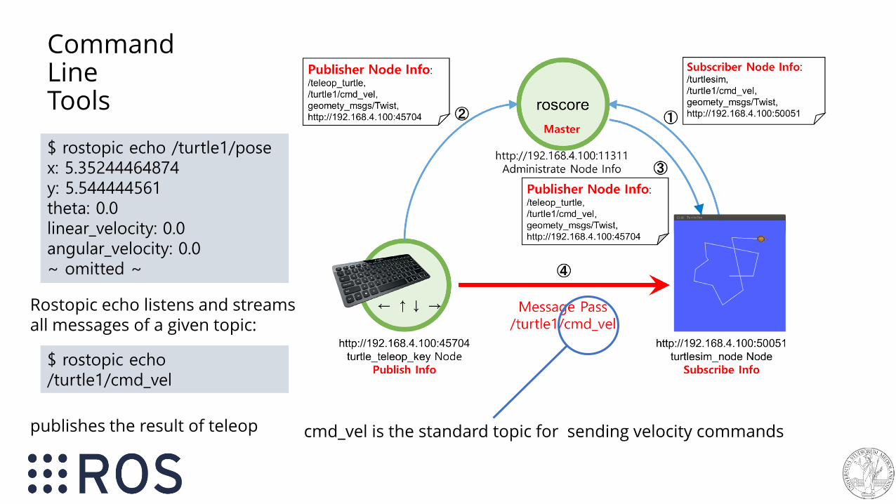
cmd_vel is the standard topic for sending velocity commands
RQT_graph shows the computational graph,Nodes and topics

CommandLineTools
cmd_vel is the standard topic for sending velocity commands
Rostopic list shows all activetopics. • cmd_vel is the velocity• pose is the (x,y) position
$ rostopic list/rosout/rosout_agg/turtle1/cmd_vel/turtle1/color_sensor/turtle1/pose
cmd_vel is the standard topic for sending velocity commands
Rostopic echo listens and streams all messages of a given topic:
publishes the result of teleop
$ rostopic echo /turtle1/posex: 5.35244464874y: 5.544444561theta: 0.0linear_velocity: 0.0angular_velocity: 0.0~ omitted ~
$ rostopic echo /turtle1/cmd_vel
Command LineTools

cmd_vel is the standard topic for sending velocity commands
rostopic pub allows to publish a message on a topic manually
$ rostopic pub -1 /turtle1/cmd_velgeometry_msgs/Twist -- '[2.0, 0.0, 0.0]' '[0.0, 0.0, 1.8]'publishing and latching message for 3.0 seconds
Command LineTools

$ rostopic pub -1 /turtle1/cmd_velgeometry_msgs/Twist -- '[2.0, 0.0, 0.0]' '[0.0, 0.0, 1.8]'publishing and latching message for 3.0 seconds
$ rostopic echo /turtle1/posex: 5.35244464874y: 5.544444561theta: 0.0linear_velocity: 0.0angular_velocity: 0.0~ omitted ~
$ rostopic list/rosout/rosout_agg/turtle1/cmd_vel/turtle1/color_sensor/turtle1/pose
One of the (most) useful feature of ROS are command line tools.
Command line tools allows the inspection of communication between nodes, to see if naming of topics and nodes is properly set, and to manually trigger messages.
ROS command line tools are designed not to write all commands directly but to let ROS autocomplete them with the Tab button.
Structure of messages, packages and topic names are automatically autocompleted by ROS –facilitating development and preventing erros.
Moreover, if ROS cannot autocomplete a message it usually indicates that something is going wrong with such topic/node/message

Turtlesim and services
Turtlesim offers also some services – e.g. in this case changing the color of the robot trajectory
Rosservice call is the command used for triggering manually a ROS service (also here, let ROS to autocomplete the call to service for you)
$ rosservice call /turtle1/set_pen 255 0 0 5 0
$ rosservice list
$ rosservice args /turtle1/set_penr g b width off

Turtlesim and params
Try to run “rosparam get” and “rosparam set” and let ROS to autocomplete (tab)
Rosparam is the command line tool for accessing all param of the parameter service. Turtlesim has background colors as params
$ rosparam list/background_b/background_g/background_r/rosdistro/roslaunch/uris/host_192_168_1_100__39536/rosversion/run_id
$ rosparam set background_b 0$ rosservice call clear

Turtlesim and rosbags$ rosbag record /turtle1/cmd_vel
[INFO] [1499663788.499650818]: Subscribing to /turtle1/cmd_vel
[INFO] [1499663788.502937962]: Recording to 2017-07-10-14-16-28.bag.
$ rosbag play 2017-07-10-14-16-28.bag
[INFO] [1499664453.406867251]: Opening 2017-07-10-14-16-28.bag
Waiting 0.2 seconds after advertising topics... done.
Hit space to toggle paused, or 's' to step.
[RUNNING] Bag Time: 1499663790.357031 Duration: 0.000000 / 17.419737
~ omitted ~.
saves messages of /turtle1/cmd_vel into a bag
Replays the same bag and publishon /turtle1/cmd_vel

Autonomous navigation with

Robot Navigation
Navigation is the ability to determine the position of the robot and to plan a path towards a goal location.
Navigation is a core capability of autonomous mobile robots, but is also dependent on several complex and stacked behaviors.

ROS and navigation
• how navigation is done is based on sensors mounted on the robot
• navigation sub-tasks depend on which is the goal of the robot (USAR, service robot, teaching, …)(e.g. a robot working in close contact with humans, should take that intoaccount)
ROS provides support in both directions:
• integration and drivers for sensors
• ready to use modules

Today’s talk
• Overview of robot sensors
• Overview of what are the sub-tasks that the robot has to perform for navigation
• How to use all of this in ROS with the ROS Navigation Stack – wheeled ground robots

Robot and sensors

Robot Sensors• sensors are the main and primarily
source of knowledge of a mobile robot
• sensors are noisy, inaccurate
• some of these inaccuracies can be modeled, some not
• sensors are raw data and do not have any semantic • humans can interpret the data
(we have semantic knowledge)• robot can’t (unless you implement it)

Sensors
• proprioceptive – info about the robot internal state• speed
• battery
• encoders
• exteroceptive – info about the world• vision
• 2D/3D
• olfaction
• chemicals
• active and passive (e.g. sonars and microphones)

Proprioceptive sensors
• wheel encoders
• IMU• accellerometers
• gyros
Integration of proprioceptive sensor data are used for open-loop estimation of the robot state.
Errors in sensors are integrated too so the estimate state gets less and less accurate with operational time

OdometryOdometry is the use of data from motion sensors to estimate change in position over time, to estimate the robot position relative to a starting location.
It could be used open-loop to estimate the robot position, butneeds integration.
Rotational movements are fare more difficult to measure than translational ones.

Odometry
Sometimes odometry is so noisy that is reconstructedfrom exteroceptive sensors
From https://doi.org/10.1109/TRO.2018.2861911

Excteroceptive sensors (for navigation)
• laser rangescanner (LIDAR)2D and 3D velodyne
• camera (stereo – mono)
• RGBD camera
• sonars
• …

2D lidar
• (probably the most used sensors in robotics)
• 2D representation of the environment
• highly reliable
• widely adopted and used also on commercial platforms
• measure time of flight of laser beam

2D lidar specs
• usable range 3-5m (indoor) 30-50m (outdoor)
• 1hz – 50hz
• relatively cheap (0.5k – 15k) (1k for a good indoor one,10k for a «good one»)
• Wide FOV (180° → 360°)
• Security for collision detection
• not subject to environmental changes (e.g. day/light)

• reliable
• cheap
• easy to use and to process
• robust to changes in the environment and to light changes
• large FOV
• long range
• outdoor and indoor
• useful for mapping, localization and path planning
2D LIDAR PROs

2D LIDAR CONs
• not that much info (2D)
• difficult to add semanticknowledge(only occupancy)
• reflections / mirrors are a problem
• planar – only object at a givenheight can be perceived (e.g. chairs, tables are not visible)
• not suited for UAV (drones)or in general to non-wheeledmobile robots
This does not exists! It’s a mirror
These are two chairs and a table

3D LIDAR - velodyne
• multi-layer lidar
• highly reliable
• 3D representation of the environment
• wide range of application(autonomous cars)
• semantic knowledge can be added
• used mostlyoutdoor

3D LIDARs
• Usually 360° and higher range than 2D LIDAR
• thicker representation close to the source andcoarser w.r.t the distance (all planar scans start from the same point)
• not subject to lighting condition changes (e.g. night)
• very expensive (10k-100k)
• most indoor application are still based on a 2D map
Currently, 2D lidars are preferred to 3D ones only for their price

Cameras (monocular)
• perceive lots of data
• easy to add semantic knowledge (e.g. object recognition, people detection, classification…)
• cheap (10$ → 10k)
• no depth info
• limited range + distortion
• difficult to be used to build a map of the environment
• subject to light changes / day-night changes, …
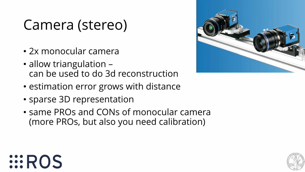
Camera (stereo)
• 2x monocular camera
• allow triangulation –can be used to do 3d reconstruction
• estimation error grows with distance
• sparse 3D representation
• same PROs and CONs of monocular camera(more PROs, but also you need calibration)

RGBD Camera• camera + depth information using an active sensor
• easier to reconstruct 3D image of the environment
• good for a lot of sensing tasks (e.g. human detection)
• widely used and useful, especially indoor
• limited range (useless at 3/5m, some even before)
• distortion
• very cheap (100$→1000$)

What sensors for navigation?
• 2D lidars provide cheap, reliable, long-range knowledge of the environment but…
• …are planar and little to none semantic knowledge
• cameras (RBGD) have limited range and are noisy and subject to light changes, but…
• … provide a lot of data
Why not use both together?Strands Scitos G5
2D LIDAR (SICK LMS)2x RBGD CAMERA

Our Giraff robot
• 2D lidar at the bottom for mapping and navigation
• an RBGD camera (Orbbec ASTRA)at the top, pointing downwardsfor detecting obstacles (tables)and help navigation
• another RGBD camera on the neck pointing upwards for people/object detection

From sensors to navigation
for moving autonomously the robot should be able tounderstand the environment from its sensor measurement
mapping
path planning
localization
SLAM
exploration
From [Grisetti, Burgard, Stachniss]

What is needed for navigation?• sensors measurement → what I can see?
• map → what is the environment?
• localization → where am I?
• path planning → how I go there?
Besides this, there are many other subtasks: mapping (creation of the map) is the most important one.
Note that we are not considering who is deciding where and how the robot should go (reasoning)

Map
• a map is a representation of the environment where the robot is operating
• Metric map
• 2D or 3D
• grid map
• feature based
• landmark-base
• Topological map
• hybrid maps
More maps could be used at the same time by a robot

Topological and hybrid maps
Topological maps are an abstract graph representation of the environment, which could be used jointly with the metric map.
From Krajnik et al, T-RO, 2017

Localization
• the robot should know its position (a pose, in 2D is a <x,y,theta>vector)in the map (reference frame)
• when the robot move theposition is updated accordingto the measurementsperformed from start till thecurrent (latest) sensormeasurement

AMCL
• a method widely used is Adaptive Monte Carlo Localization (AMCL)
• available in ROS and deault localization method in the navigation stack(more later)
• particle-based (several estimated location are maintained and updated together, the more the “cloud” of particles is thick, the more precise is the localization

Mapping
Given the robot position, a sequence of measurements (and the position from which those measurements have been
performed), build the map of the environment
How to know the robot position in the map, if I have no map?
We need to solve a bigger problem

SLAM: Simoultaneous Localization and MappingEstimate:
• the map of the environment
• the trajectory of a moving device
using a sequence of sensor measurements
SLAM is one of the core problems in robotics, widely studiedand hundreds of solutions proposed during 20+ years

SLAM: Simoultaneous Localization and MappingSLAM approaches can be different w.r.t the type of the robot:
• indoor
• outdoor
• marine (water-surface or submarine)
• underground
• …
The type of map built (2D/3D) and the type of sensors used for mapping (2D/3D lidars, vision, sonars, …)

2D SLAM• used for indoor environments
• 2D grid maps
• robust
• available and ready-to-use solutions
• 2D lidar as source (cheap and reliable)
• most algorithms (e.g. planning) assume are designed for working with such representation
• most methods are based on FiltersKalman filter, EKF, particle filter, …

2D SLAM in ROS
• several available methods – widely used, tested and robust
• need parameter configuration, but it is not that hard + docs
• Gmapping [Grisetti et al, T-RO, 2009] and Hector SLAM are the most popular ones
• work reasonably well with a lot of different robotplatform/settings, are robust to changes and clutter (noise in sensors and furniture, …), complex and large-scale environments, …
http://wiki.ros.org/gmappinghttp://wiki.ros.org/hector_slam

2D SLAM
• SLAM is the process used for building the map
• you start assuming no-knowledge of the environment and the map is built incrementally
• in most setting you can map the environment once and use the map later for future uses
• assumption: the environment is static (open/closed doors)
• dynamic changes (e.g. people) can be filtered out (while mapping) and are not present when a static map is used…
• …low-freq dynamic changing (e.g. doors) and static changing could jeopardize robot localization and navigation → redo mapping or use dynamic mapping mechanisms

ROS Navigation stack• assumptions: you have selected a set of sensors, the robot
architecture, and you have chosen your favorite localization algorithm (AMCL default) and have a map
• map can be given (so you use a previously acquired map) orbeing built incrementally (SLAM)
• ROS navigation stack handles this setting and allows path planning: finding if exists a list of robot positions that, if followed, allows the robot to reach its goal
• also, it allows the execution of this path
• the core of the method is called move_base
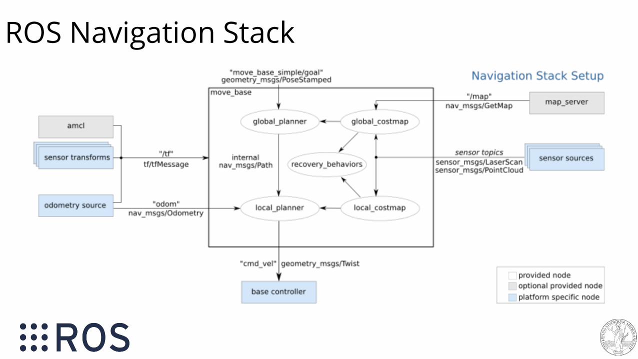
ROS Navigation Stack

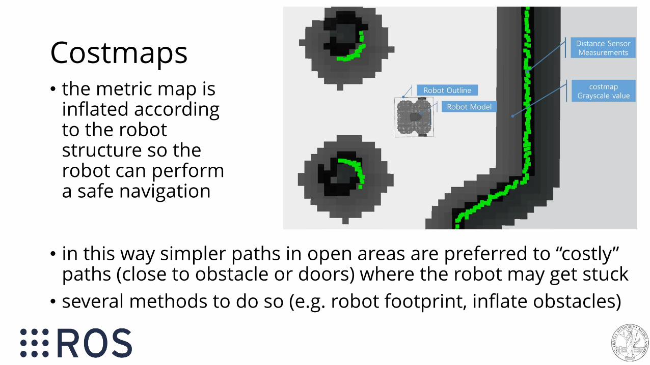
Costmaps• the metric map is
inflated accordingto the robot structure so the robot can perform a safe navigation
• in this way simpler paths in open areas are preferred to “costly” paths (close to obstacle or doors) where the robot may get stuck
• several methods to do so (e.g. robot footprint, inflate obstacles)

Deal with uncertainties and dynamics
The robot plans its path in the static map but• changes usually happens (doors open/close)
• new obstacles may appear (people, animals, children)
• the robot movements execution are very different w.r.t. the initial goal
• …
Solution: complement the (ideal) map with local information coming for sensors that address such issues
• obstacle avoidance
• local map refinement based on recent sensor readings

ROS Navigation Stack

Global and local planner
• global plan → identifies the long-term path that eventually will lead the robot to the goalworks at low frequency, using 2D lidar data
• global costmap→ used for path planning, based on the static metric map
• local plan → identify the next moves that the robot has toperform in order to follow the global path works at high frequency
• local costmap→ centered on the robot, integrates all of the sensors of the robot (2D lidar, RGBD data, bumpers) that are needed to constantly adapt the local plan

Global planner and costmaps
• implements several planning algorithms, use the one you want and that is most suited for your application
• costmaps also can be tuned in several ways according toyour robot configuration
• you can visualize with RViz the path decided by the robot
• the global path could become outdated – replanning is also used

Global Planner
A* Potential

ROS Navigation Stack
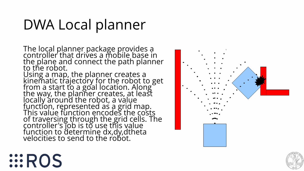
DWA Local planner
The local planner package provides a controller that drives a mobile base in the plane and connect the path planner to the robot. Using a map, the planner creates a kinematic trajectory for the robot to get from a start to a goal location. Along the way, the planner creates, at least locally around the robot, a value function, represented as a grid map. This value function encodes the costs of traversing through the grid cells. The controller's job is to use this value function to determine dx,dy,dthetavelocities to send to the robot.

DWA Local Planner
Dynamic Window Approach to local robot navigation on a plane. Given a global plan to follow and a costmap, the local planner produces velocity commands to send to a mobile base.
The basic idea of the Dynamic Window Approach (DWA) algorithm is as follows:
• discretely sample in the robot's control space (dx,dy,dtheta)
• for each sampled velocity, perform forward simulation from the robot's current state to predict what would happen if the sampled velocity were applied for some (short) period of time.
• evaluate (score) each trajectory resulting from the forward simulation, using a metric that incorporates characteristics such as: proximity to obstacles, proximity to the goal, proximity to the global path, and speed. Discard illegal trajectories (those that collide with obstacles).
• pick the highest-scoring trajectory and send the associated velocity to the mobile base.
• rinse and repeat.

Handling failures
• despite the integration of local and global plan execution, the robot may get stuck → is not able to move and continue to execute its path
• this happens often in narrow passages (doorways), when a lot of rotations are involved, or with dynamic obstacles (people, is too close to an obstacle to safely move)
• the robot should be provided with mechanism to solve autonomously such issue and to restart following its path
• otherwise, a human intervention is needed
The navigation stack gives you a set of behavior for this

Recovery Behaviors
Recovery behaviors are executed when the robot is stuck or cannot proceed tothe goal (cannot execute the path or cannot compute the path). They try to free the robot from a dangerous position (e.g. too close to an obstacle) or to “clear” the costmaps (e.g. a noisy reading, a user was in front of the robot, an obstacle that was there and it is not there anymore)

An example of global and local costmaps + AMCL
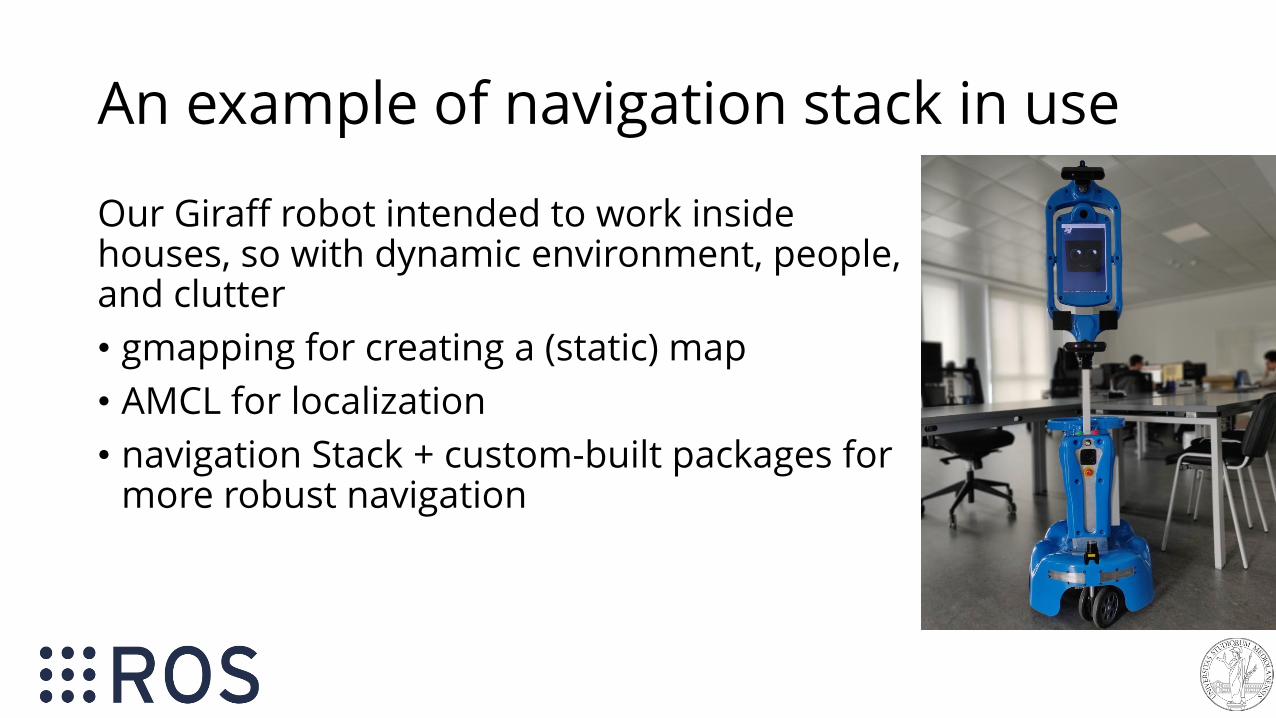
An example of navigation stack in use
Our Giraff robot intended to work inside houses, so with dynamic environment, people, and clutter
• gmapping for creating a (static) map
• AMCL for localization
• navigation Stack + custom-built packages formore robust navigation

An example of navigation stack in use
• the global costmap (and the map) is built using a 2D lidar 20cm from the ground
• the local costmap is integrated with depth sensor info projected at the 2D plane from 2 RBGD cameras, one pointing on the ground, the other one front-facing
• In this way the robot can detect people,tables, chairs, …
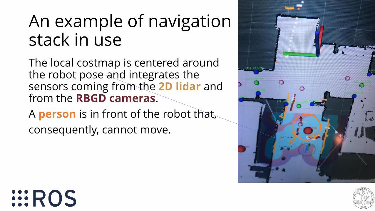
An example of navigation stack in use The local costmap is centered around the robot pose and integrates the sensors coming from the 2D lidar and from the RBGD cameras.
A person is in front of the robot that,
consequently, cannot move.

ROS Navigation wrap up
All the required modules for having a robot moving autonomously are available and ready-to use in ROS.
You just need to:
• select sensors and a robot
• pick up a SLAM algorithm and make a map
• use a localization mechanism
• use the navigation stack

ROS Navigation wrap upYou can use simulations and test everything you’ve seen by yourself in a couple of afternoons
RViz is very useful to test and understand what happens.

ROS navigation wrap up mapping
path planning
localization
SLAM
exploration
From [Grisetti, Burgard, Stachniss]
Remember that navigation is acore behavior of the robot, ontop of which more complexones are built.
E.g. exploration is the task of building a map of an unknownenvironment, making decision about the next position that has to be reached (next path planning goal).

Sources - References
• Wiki.ros.org
• ROS Robot Programming A Handbook Written by Turtlebot3 Developers (available at http://www.robotis.com/service/download.php?no=719)
• Robotis Turtlebot3 documentationhttp://emanual.robotis.com/docs/en/platform/turtlebot3/getting_started/
• Jason O’Kane, A Gentle Introduction to ROShttps://cse.sc.edu/~jokane/agitr/agitr-letter.pdf
Sources - References on navigation
ROS wiki navigation stack home page, with a lot of tutorialsand documentation
• http://wiki.ros.org/navigation
• http://wiki.ros.org/navigation#Tutorials
• http://wiki.ros.org/navigation/Tutorials/Using%20rviz%20with%20the%20Navigation%20Stack
Next lesson
Mercoledì 30/10 non ci sarà lezione
In alternativa, abbiamo organizzato una demo in cui potrete provare quanto visto in questi ultimi due seminari dal vivo, usando i nostri turtlebot3. simulazione + robot

Next lesson
Dove: AisLab
Dipartimento di Informatica (Via Celoria 18) IV piano – telefono 16328
Quando: Mercoledì 30/10, 9:00 → 10:30
Se siete interessati a partecipare, per questioni di capienza,segnalatelo sul doodle.https://doodle.com/poll/rmm5upk6dzqcr5dkindicate nel nome la vostra mail – nel caso foste tanti vi divideremo in slot orari.